- Preface
- Introduction to the CRS-3 Back-to-Back System
- Cabling for System Management, Alarms, and Network Clocking
- Cabling the CRS-3 Back-to-Back System
- Upgrading to a CRS-3 Back-to-Back System Using Cisco IOS-XR 4.3.1 or Earlier
- Upgrading to a CRS Back-to-Back System Using Cisco IOS-XR 5.1.1 or Later
Cabling the CRS-3 Back-to-Back System
The cables used to interconnect the CRS-3 Back-to-Back System chassis are optical array cables called fabric cables. This chapter describes how to physically cable the fabric planes between 8-slot chassis in a CRS-3 Back-to-Back System. This chapter is organized into the following sections:
- About Fabric Cabling
- Planning Fabric Cabling
- Cabling the Fabric
- General Fabric Cabling Procedures
- What to Do Next
About Fabric Cabling
 Note | The cables required for an 8-slot chassis and for a 16-slot chassis in the CRS-3 Back-to-Back System are the same. |
Each CRS-3 Back-to-Back System requires 8 fabric cables. This cabling enables interchassis data communication, which is accomplished using fiber-optic bundles.
The CRS-3 Back-to-Back System uses a customized cable/connector that visually looks the same as the multichassis cable/connector with a different PIN layout. The way to distinguish the fabric cables for the CRS-3 Back-to-Back System is a label that says Back-to-Back.
This section describes the following topics:
About Fabric Planes in the CRS-3 Back-to-Back System
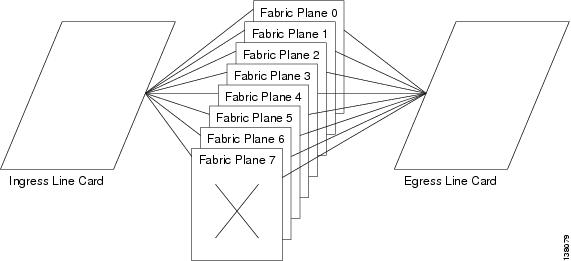
The CRS-3 Back-to-Back System has eight fabric planes that support data traffic between the lines connected to the 8-slot chassis. The below figure shows a simplified view of the relationship between the line cards and the fabric.
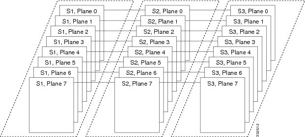
In general, CRS fabric planes are divided into three components or stages, which are numbered S1, S2, and S3. Data arrives at the S1 stage then goes through the S2 stage and exits at the S3 stage to the destination line card. The figure below shows a simplified view of the relationship between the line cards and the fabric planes in a general CRS system.
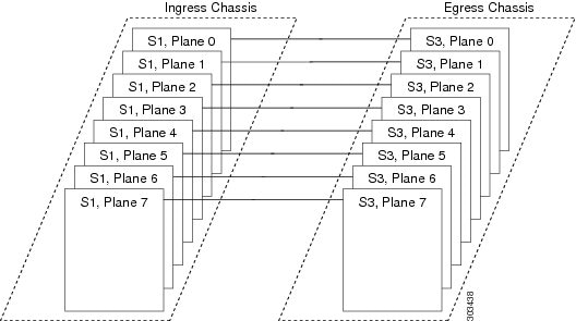
However, in a CRS-3 Back-to-Back System, fabric planes are divided into two stages: S1 and S3. The S2 stage is no longer needed. The purpose of the S2 stage is to direct traffic to the correct egress 8-slot chassis when there are multiple egress 8-slot chassis. In the CRS-3 Back-to-Back System, there is only one egress 8-slot chassis.
Data arrives at the S1 stage in the ingress 8-slot chassis and then passes over the fabric cables to the S3 stage in the egress 8-slot chassis. The figure below shows a simplified view of the relationship between the line cards and the fabric planes in a CRS-3 Back-to-Back System.
Note | Refer to Figure 1 for physical cabling examples. |
In each 8-slot chassis, one S13 fabric card supports 2 fabric planes. Therefore, there are four S13 fabric cards with 8 planes. All ingress traffic enters through the S1 stage of the ingress S13 card, travels over the fabric cables and exits through the S3 stage on an S13 fabric card. Data traffic can enter through the S1 stage on one card and then exit the S3 stage on the same card.
The figure below shows the location of the S13 fabric cards in each 8-slot chassis and how the connectors are labeled on those cards.
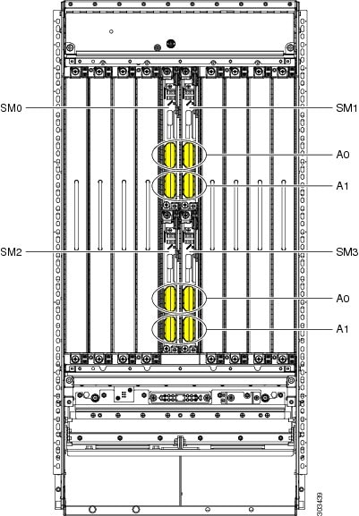
Note the following:
-
The fabric cards are numbered 0 through 3 and are installed in slot numbers SM 0 through SM 3.
-
Each fabric card has two connectors, which are labeled A0 and A1.
-
Each cable on an 8-slot chassis connects to the same connector on the other 8-slot chassis. For example, on chassis 0, the card in slot SM0 has a cable coming from the A0 connector. That cable connects to the A0 connector on the card in slot SM0 on chassis 1
.
Cisco Systems Fabric Cables
The below table lists the product ID numbers for Cisco CRS fabric cables. The cables listed in the table below can be ordered. The interconnection cables listed are shipped as a set of 8 in the meter length specified. Evaluate your installation for the appropriate length of fabric cable needed before ordering. You should try to avoid long runs of coiled cables.
In the below table, the cable name CRS-B2B-CAB-XX means the following:
-
CRS is Carrier Routing System.
-
B2B is back-to-back.
-
CAB is cable or optical cable.
-
xx is the length of the cable in meters.
Note | The = symbol at the end of a product ID number indicates that the part is a spare , which means that the cable can be ordered as a spare.The R symbol at the end of a product ID number indicates that the part is a Riser cable. |
|
Fabric Cable Product ID |
Description and Length |
|---|---|
|
CRS-B2B-CAB-10 |
Cisco CRS-3 Back-to-Back Optical Cable 10 meters (32.8 feet) |
|
CRS-B2B-CAB-10= |
|
|
CRS-B2B-CAB-10R |
Cisco CRS-3 Back-to-Back Optical Cable Riser 10 meters (32.8 feet) |
|
CRS-B2B-CAB-10R= |
|
|
CRS-B2B-CAB-15 |
Cisco CRS-3 Back-to-Back Optical Cable 15 meters (49.2 feet) |
|
CRS-B2B-CAB-15= |
|
|
CRS-B2B-CAB-15R |
Cisco CRS-3 Back-to-Back Optical Cable Riser 15 meters (49.2 feet) |
|
CRS-B2B-CAB-15R= |
|
|
CRS-B2B-CAB-20 |
Cisco CRS-3 Back-to-Back Optical Cable 20 meters (65.6 feet) |
|
CRS-B2B-CAB-20= |
|
|
CRS-B2B-CAB-20R |
Cisco CRS-3 Back-to-Back Optical Cable Riser 20 meters (65.6) |
|
CRS-B2B-CAB-20R= |
|
|
CRS-B2B-CAB-25 |
Cisco CRS-3 Back-to-Back Optical Cable 25 meters (82 feet) |
|
CRS-B2B-CAB-25= |
|
|
CRS-B2B-CAB-25R |
Cisco CRS Line Card Chassis-Fabric Chassis Riser 25 meters (82 feet) |
|
CRS-B2B-CAB-25R= |
|
|
CRS-B2B-CAB-30 |
Cisco CRS-3 Back-to-Back Optical Cable 30 meters (98.43) |
|
CRS-B2B-CAB-30= |
|
|
CRS-B2B-CAB-30R |
Cisco CRS-3 Back-to-Back Optical Cable Riser 30 meters (98.43 feet) |
|
CRS-B2B-CAB-30R= |
|
|
CRS-B2B-CAB-40 |
Cisco CRS-3 Back-to-Back Optical Cable 40 meters (131.2 feet) |
|
CRS-B2B-CAB-40= |
|
|
CRS-B2B-CAB-40R |
Cisco CRS-3 Back-to-Back Optical Cable Riser 40 meters (131.2 feet) |
|
CRS-B2B-CAB-40R= |
|
|
CRS-B2B-CAB-50 |
Cisco CRS-3 Back-to-Back Optical Cable 50 meters (164 feet) |
|
CRS-B2B-CAB-50= |
|
|
CRS-B2B-CAB-50R |
Cisco CRS-3 Back-to-Back Optical Cable Riser 50 meters (164 feet) |
|
CRS-B2B-CAB-50R= |
|
|
CRS-B2B-CAB-60 |
Cisco CRS-3 Back-to-Back Optical Cable 60 meters (197 feet) |
|
CRS-B2B-CAB-60= |
|
|
CRS-B2B-CAB-60R |
Cisco CRS-3 Back-to-Back Optical Cable Riser 60 meters (197 feet) |
|
CRS-B2B-CAB-60R= |
|
|
CRS-B2B-CAB-70 |
Cisco CRS-3 Back-to-Back Optical Cable 70 meters (229.7) |
|
CRS-B2B-CAB-70= |
|
|
CRS-B2B-CAB-70R |
Cisco CRS-3 Back-to-Back Optical Cable Riser 70 meters (229.7) |
|
CRS-B2B-CAB-70R= |
|
|
CRS-B2B-CAB-80 |
Cisco CRS-3 Back-to-Back Optical Cable 80 meters (262.5 feet) |
|
CRS-B2B-CAB-80= |
|
|
CRS-B2B-CAB-80R |
Cisco CRS-3 Back-to-Back Optical Cable Riser 80 meters (262.5 feet) |
|
CRS-B2B-CAB-80R= |
|
|
CRS-B2B-CAB-90 |
Cisco CRS-3 Back-to-Back Optical Cable 90 meters (295.3feet) |
|
CRS-B2B-CAB-90= |
|
|
CRS-B2B-CAB-90R |
Cisco CRS-3 Back-to-Back Optical Cable Riser 90 meters (295.3 feet) |
|
CRS-B2B-CAB-90R= |
|
|
CRS-B2B-CAB-100 |
Cisco CRS-3 Back-to-Back Optical Cable 100 meters (328 feet) |
|
CRS-B2B-CAB-100= |
|
|
CRS-B2B-CAB-100R |
Cisco CRS-3 Back-to-Back Optical Cable Riser 100 meters (328 feet) |
|
CRS-B2B-CAB-100R= |
Planning Fabric Cabling
Planning the fabric cabling involves the following components:
Chassis Cable Routing
When planning your cable runs, it is convenient when cables are planned, labeled, and hung from overhead cable troughs so that the end of the cable is almost touching the floor. Allow more or less slack as cables are connected.
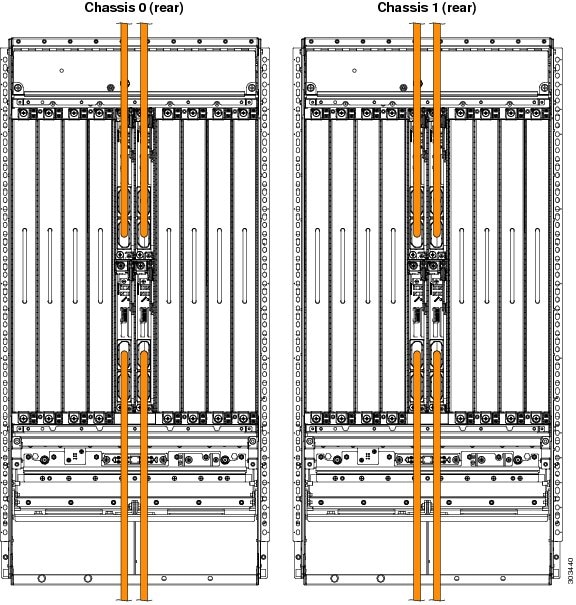
Before you begin cabling, develop a cabling plan for your CRS-3 Back-to-Back System. The example in the figure below shows that the cable from the top two fabric cards are routed upwards, and the cable from the bottom two fabric cards are routed downwards.
When preparing to cable the CRS-3 Back-to-Back System, consider the following information:
-
You can connect the fabric cards in any order. For example, you can start connecting SM3 first.
-
The bend radius of each fabric cable should be no smaller than the arc of the turn collar support.
-
Always put the turn collar on the fabric cable before inserting the cable connector into the connector, as described in the Installing Turn Collars.
-
When you install a fabric cable connector into a fabric card connector, hand-tighten the screws. After you have installed all the fabric cable connectors that go on a fabric card, bundle the cables gently, in sequence, using the Velcro tie wrap on each turn collar. Use additional Velcro tie wraps as needed to route the cables.
-
Fabric cables have dust covers, held on by two screws. Fabric card connectors have yellow dust covers that snap on and off. When you take dust covers off, do not put them where they can collect dust. Store unused dust covers in a clean, dust-free area.
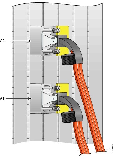
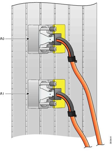
The below figures provide a close up view of the cables attached to the fabric card.
Planning Cable Labels
Label cables as you unpack them. With a felt-tip pen, mark cables as 1, 2, 3 , and so on. Create a consistent labeling scheme. This section suggests a labeling scheme.
Use a label size that works best at your installation. Each label should contain the from and to port location at which either end of the cable is attached. For example, a label could contain the following information:
From:
Chassis #
Slot #/Port #
To:
Chassis #
Slot #/Port #
Where:
- Chassis # is the number for the chassis.
-
Slot #/Port #
are slot and port numbers (for example, SM3/A0, which means slot SM3, connector A0). To further explain:
- SM0 through SM3 are slot numbers because there are 4 switch module slots that are numbered 0 through 3.
- A0 through A1 match fabric card port numbers on the S13 card.
Label Schema Example
Note the following:
-
The 8-slot chassis has four fabric card slots.
-
The CRS-8-FC140/M fabric card has two connectors. For example, a fabric card in 0/SM0/SP has two connectors, 0/SM0/SP/0 and 0/SM0/SP/1.
-
The fabric bundle optical connection using fabric cable between chassis are as below:
Chassis 0 Chassis 1
0/SM0/SP/0---------------------------------1/SM0/SP/0
0/SM0/SP/1---------------------------------1/SM0/SP/1
0/SM1/SP/0---------------------------------1/SM1/SP/0
0/SM1/SP/1---------------------------------1/SM1/SP/1
0/SM2/SP/0---------------------------------1/SM2/SP/0
0/SM2/SP/1---------------------------------1/SM2/SP/1
0/SM3/SP/0---------------------------------1/SM3/SP/0
0/SM3/SP/1---------------------------------1/SM3/SP/1
Note | For control Ethernet cabling, see Figure 1. |
We suggest that you use a labeling schema, for example, with an Excel spreadsheet. The sample label schema shown in the below table uses the following convention: chassis_number /slot_number /port_number . Note the following:
-
Each cable should have a minimum of two labels, one label for each end.
-
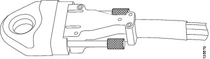
Do not apply the label within 2.5 inches (6.4 cm) from the point at which the cable meets the connector, or the label will be covered by the turn collar. In addition, if the label is farther than 3.5 inches (8.9 cm) from the point at which the cable meets the connector, it might be obscured by the collar of an adjacent cable when installed. A turn collar is shown in Figure 2.
|
Plane |
Chassis 0 Label |
Chassis 1 Label |
|---|---|---|
|
0 |
0/SM0/A0 |
1/SM0/A0 |
|
1 |
0/SM0/A1 |
1/SM0/A1 |
|
2 |
0/SM1/A0 |
1/SM1/A0 |
|
3 |
0/SM1/A1 |
1/SM1/A1 |
|
4 |
0/SM2/A0 |
1/SM2/A0 |
|
5 |
0/SM2/A1 |
1/SM2/A1 |
|
6 |
0/SM3/A0 |
1/SM3/A0 |
|
7 |
0/SM3/A1 |
1/SM3/A1 |
Cabling the Fabric
Precautions
Please observe all precautions listed in the General Safety Guidelines when you perform any procedure in this chapter. The following precautions are additional reminders before you begin cabling the CRS-3 Back-to-Back System.
 Warning | Because invisible radiation may be emitted from the aperture of the port when no fiber cable is connected, avoid exposure to radiation and do not stare into open apertures. Statement 125 |
Warning | During this procedure, wear grounding wrist straps to avoid ESD damage to the card. Do not directly touch the backplane with your hand or any metal tool, or you could shock yourself. Statement 94 |
Warning | Before working on equipment that is connected to power lines, remove jewelry (including rings, necklaces, and watches). Metal objects will heat up when connected to power and ground and can cause serious burns or weld the metal object to the terminals. Statement 43 |
If a chassis power is on, assume lasers are turned on.
Never look at the ends of the fiber cables unless you are certain the laser is powered off.
The S13 card is Class 1M. Other optical cards are Class 1.
Warning | For diverging beams, viewing the laser output with certain optical instruments within a distance of 100 MM. may pose an eye hazard. For collimated beams, viewing the laser output with certain optical instruments designed for use at a distance may pose an eye hazard. Statement 282 |
Warning | Laser radiation. Do not view directly with optical instruments. Class 1M laser product. Statement 283 |
 Caution | Handle cables carefully, as described in Introduction to the CRS-3 Back-to-Back System |
Caution | Cleanliness is critical to proper switch operation. To keep connections clean, do not remove the yellow dust cover from a port until you are ready to attach a cable. Do not remove the silver dust cover from a fabric cable until you are ready to attach the cable to the fabric card connector. Silver dust covers should be screwed on for security. Loosen the screws to remove the dust cover (see figure below). Store dust covers in a dust-free location. |
Prerequisites
Cable connection procedures assume that all 8-slot chassis and their cards are installed in accordance with site planning guidelines and that appropriate interconnection cable lengths are ordered and ready to be connected.
Caution | All ports should have yellow dust covers on them as you begin this procedure, as shown in Figure 4. |
How to Connect the Fabric Cables
The fabric cables are shipped separately from the fabric card chassis. These cables are shipped on a reel, similar to as shown in the below figure. This procedure begins with the assumption that the fabric cables have been unpacked and positioned or hung near the chassis to which they will be connected. Packaging for Riser cables may differ from the figure below.
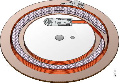
You will be attaching 8 fabric cables for each 8-slot chassis. Ensure that each cable is labeled at both ends and then run each cable between the two 8-slot chassis.
Attach 8-Slot Chassis
The steps to take while attaching each cable to the 8-slot chassis follow:
1. Slide the turn collar support on in the direction shown below:Top two fabric cards - all turn collars go up. Bottom two fabric cards - all turn collars go down.
2. Gently position the connector in the correct orientation (fabric card connectors and fabric cable connectors are keyed).
3. Hand-tighten the thumbscrews on the connector.
4. Repeat Steps 1 through 3 to each cable.
5. Fully tighten every connection.
6. Gently drape and group cables behind the fabric card.
DETAILED STEPS
| Step 1 | Slide the turn collar support on in the direction shown below:Top two fabric cards - all turn collars go up. Bottom two fabric cards - all turn collars go down. |
| Step 2 | Gently position the connector in the correct orientation (fabric card connectors and fabric cable connectors are keyed). |
| Step 3 | Hand-tighten the thumbscrews on the connector. |
| Step 4 | Repeat Steps 1 through 3 to each cable. |
| Step 5 | Fully tighten every connection. |
| Step 6 | Gently drape and group cables behind the fabric card. |
General Fabric Cabling Procedures
The following are general fabric cabling procedures you might want to use when installing or maintaining the fabric cabling:
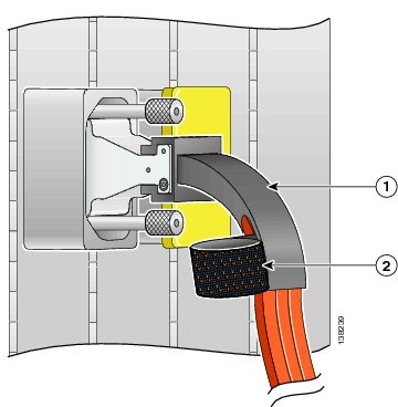
Installing Turn Collars
The turn collar protects the fabric cable bend radius and functions as a strain-relief support. It also has a Velcro strap attached to it to bundle the cables as the cables are installed.
Here are notes to help you install a turn collar:
-
The connector is keyed. One side is flat, and the other side has a diagonal cut from the corners.
-
Connectors in S13 cards have the flat side on the right.
-
Turn collars can be slipped onto either side of the connector, depending on whether the cable should turn up or down for proper routing through the chassis.
To install a turn collar:
1. Undo the Velcro strap. See figure Turn Collar - Trimese Cable below.
2. Slide the cable into the turn collar until the cable is seated and snaps into place.
3. Attach the Velcro strap around the cable to hold the cable in place. See Turn Collar - Riser Cable figure below.
DETAILED STEPS
What to Do Next
1
Turn collar
2
Velcro strap (to keep the fabric cable inside the turn collar and bundle fabric cables)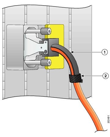
Cleaning Cables
For information about cleaning fiber-optic cables, see the Cisco CRS-1 Carrier Routing System Fiber-Optic Cleaning Guide .
Verifying the Fabric
This section describes the processes for executing the commands required to verify the fabric. All commands in this mode will be run from admin mode.
1. To verify the fabric card status:
2. To verify the rack status:
3. To verify the plane status and the plane mode status:
4. To verify the bundle status:
5. To verify the link status across the specific bundle, use the following command:
6. To verify the number of RX (receive) and TX (transmit) links up in the bundle across the bundle:
7. To verify the fabric connectivity across the racks:
8. To verify the back pressure group summary for the Cisco CRS-3 Back-to-Back system:
DETAILED STEPS
| Step 1 |
To verify the fabric card status: Example: RP/0/RP0/CPU0:b2b(admin)#show platform | in SM 0/SM0/SP FC-140G/M(H)(SP) N/A IOS XR RUN PWR,NSHUT,MON 0/SM1/SP FC-140G/M(H)(SP) N/A IOS XR RUN PWR,NSHUT,MON 0/SM2/SP FC-140G/M(H)(SP) N/A IOS XR RUN PWR,NSHUT,MON 0/SM3/SP FC-140G/M(H)(SP) N/A IOS XR RUN PWR,NSHUT,MON 1/SM0/SP FC-140G/M(H)(SP) N/A IOS XR RUN PWR,NSHUT,MON 1/SM1/SP FC-140G/M(H)(SP) N/A IOS XR RUN PWR,NSHUT,MON 1/SM2/SP FC-140G/M(H)(SP) N/A IOS XR RUN PWR,NSHUT,MON 1/SM3/SP FC-140G/M(H)(SP) N/A IOS XR RUN PWR,NSHUT,MON | ||
| Step 2 |
To verify the rack status: Example: RP/0/RP0/CPU0:b2b(admin)#show controllers fabric rack all detail Rack Rack Server Num Status Status ---- ------ ------ 0 NORMAL PRESENT 1 NORMAL PRESENT | ||
| Step 3 |
To verify the plane status and the plane mode status: Example:
RP/0/RP0/CPU0:b2b(admin)#show controllers fabric plane all detail
  Flags: P - plane admin down,       p - plane oper down
         C - card admin down,        c - card  oper down
         A - asic admin down,        a - asic oper down
         L - link port admin down,   l - linkport oper down
         B - bundle port admin Down, b - bundle port oper down
         I - bundle admin down,      i - bundle oper down
         N - node admin down,        n - node down
         X - ctrl admin down,        x - ctrl down
         o - other end of link down  d - data down
         f - failed component downstream
         m - plane multicast down,   s - link port permanently shutdown
         t - no barrier input        O - Out-Of-Service oper down
         T - topology mismatch down  e - link port control only
         D - plane admin data down   U - issu down
         u - untunable               g - tuning in progress
         v - successfully tuned at least once
         w - most recent tuning attempt failed
         h - tuning pending          z - rx-eye measurement in progress
 Plane  Admin   Oper       up->dn   up->mcast     Down    Plane      Total       Down
 Id     State   State      counter  counter      Flags     Mode    Bundles    Bundles
 -------------------------------------------------------------------------------------
 0      UP      UP           0          0                 B2B      1          0
 1      UP      UP           0          0                 B2B      1          0
 2      UP      UP           0          0                 B2B      1          0
 3      UP      UP           0          0                 B2B      1          0
 4      UP      UP           0          0                 B2B      1          0
 5      UP      UP           0          0                 B2B      1          0
 6      UP      UP           0          0                 B2B      1          0
 7      UP      UP           0          0                 B2B      1          0
| ||
| Step 4 |
To verify the bundle status: Example:
RP/0/RP0/CPU0:b2b(admin)#show controllers fabric bundle port all
  Flags: P - plane admin down,       p - plane oper down
         C - card admin down,        c - card  oper down
         A - asic admin down,        a - asic oper down
         L - link port admin down,   l - linkport oper down
         B - bundle port admin Down, b - bundle port oper down
         I - bundle admin down,      i - bundle oper down
         N - node admin down,        n - node down
         X - ctrl admin down,        x - ctrl down
         o - other end of link down  d - data down
         f - failed component downstream
         m - plane multicast down,   s - link port permanently shutdown
         t - no barrier input        O - Out-Of-Service oper down
         T - topology mismatch down  e - link port control only
         D - plane admin data down   U - issu down
         u - untunable               g - tuning in progress
         v - successfully tuned at least once
         w - most recent tuning attempt failed
         h - tuning pending          z - rx-eye measurement in progress
Bundle Port    Admin     Oper
  R/S/M/P      State     State
------------------------------
 0/SM0/SP/0    UP        UP
 0/SM0/SP/1    UP        UP
 0/SM1/SP/0    UP        UP
 0/SM1/SP/1    UP        UP
 0/SM2/SP/0    UP        UP
 0/SM2/SP/1    UP        UP
 0/SM3/SP/0    UP        UP
 0/SM3/SP/1    UP        UP
 1/SM0/SP/0    UP        UP
 1/SM0/SP/1    UP        UP
 1/SM1/SP/0    UP        UP
 1/SM1/SP/1    UP        UP
 1/SM2/SP/0    UP        UP
 1/SM2/SP/1    UP        UP
 1/SM3/SP/0    UP        UP
 1/SM3/SP/1    UP        UP
| ||
| Step 5 |
To verify the link status across the specific bundle, use the following command: Example: show controllers fabric bundle bundle port connection
For example: Example:
RP/0/RP0/CPU0:b2b(admin)#show controllers fabric bundle 1/SM0/SP/0 connection
  Flags: P - plane admin down,       p - plane oper down
         C - card admin down,        c - card  oper down
         A - asic admin down,        a - asic oper down
         L - link port admin down,   l - linkport oper down
         B - bundle port admin Down, b - bundle port oper down
         I - bundle admin down,      i - bundle oper down
         N - node admin down,        n - node down
         X - ctrl admin down,        x - ctrl down
         o - other end of link down  d - data down
         f - failed component downstream
         m - plane multicast down,   s - link port permanently shutdown
         t - no barrier input        O - Out-Of-Service oper down
         T - topology mismatch down  e - link port control only
         D - plane admin data down   U - issu down
         u - untunable               g - tuning in progress
         v - successfully tuned at least once
         w - most recent tuning attempt failed
         h - tuning pending          z - rx-eye measurement in progress
 Bundle      Oper    Down   Plane  Total   Down      Down      Bundle   Bundle
 R/S/M/P     State   Flags   Id    Links  bp1-bp2   bp2-bp1    Port1    Port2
----------------------------------------------------------------------------------------
 1/SM0/SP/0   UP              0     72     0          0       1/SM0/SP/0 0/SM0/SP/0
   Actual connection data:
   Link Port              Expected               Actual                 State
   s3rx/1/SM0/SP/0/1      s1tx/0/SM0/SP/0/135    s1tx/0/SM0/SP/0/135    UP
   s3rx/1/SM0/SP/0/3      s1tx/0/SM0/SP/0/131    s1tx/0/SM0/SP/0/131    UP
   s3rx/1/SM0/SP/0/12     s1tx/0/SM0/SP/0/129    s1tx/0/SM0/SP/0/129    UP
   s3rx/1/SM0/SP/0/5      s1tx/0/SM0/SP/0/133    s1tx/0/SM0/SP/0/133    UP
   s3rx/1/SM0/SP/0/14     s1tx/0/SM0/SP/0/130    s1tx/0/SM0/SP/0/130    UP
   s3rx/1/SM0/SP/0/7      s1tx/0/SM0/SP/0/138    s1tx/0/SM0/SP/0/138    UP
   s3rx/1/SM0/SP/0/9      s1tx/0/SM0/SP/0/132    s1tx/0/SM0/SP/0/132    UP
   s3rx/1/SM0/SP/0/6      s1tx/0/SM0/SP/0/121    s1tx/0/SM0/SP/0/121    UP
   s3rx/1/SM0/SP/0/0      s1tx/0/SM0/SP/0/143    s1tx/0/SM0/SP/0/143    UP
   s3rx/1/SM0/SP/0/11     s1tx/0/SM0/SP/0/128    s1tx/0/SM0/SP/0/128    UP
   s3rx/1/SM0/SP/0/2      s1tx/0/SM0/SP/0/120    s1tx/0/SM0/SP/0/120    UP
   s3rx/1/SM0/SP/0/13     s1tx/0/SM0/SP/0/141    s1tx/0/SM0/SP/0/141    UP
   s3rx/0/SM0/SP/0/1      s1tx/1/SM0/SP/0/135    s1tx/1/SM0/SP/0/135    UP
   s3rx/0/SM0/SP/0/3      s1tx/1/SM0/SP/0/131    s1tx/1/SM0/SP/0/131    UP
   s3rx/0/SM0/SP/0/12     s1tx/1/SM0/SP/0/129    s1tx/1/SM0/SP/0/129    UP
   s3rx/0/SM0/SP/0/5      s1tx/1/SM0/SP/0/133    s1tx/1/SM0/SP/0/133    UP
   s3rx/0/SM0/SP/0/14     s1tx/1/SM0/SP/0/130    s1tx/1/SM0/SP/0/130    UP
   s3rx/0/SM0/SP/0/7      s1tx/1/SM0/SP/0/138    s1tx/1/SM0/SP/0/138    UP
   s3rx/0/SM0/SP/0/9      s1tx/1/SM0/SP/0/132    s1tx/1/SM0/SP/0/132    UP
   s3rx/0/SM0/SP/0/6      s1tx/1/SM0/SP/0/121    s1tx/1/SM0/SP/0/121    UP
| ||
| Step 6 |
To verify the number of RX (receive) and TX (transmit) links up in the bundle across the bundle: Example:
RP/0/RP0/CPU0:b2b(admin)#show controllers fabric link health
  Flags: P - plane admin down,       p - plane oper down
         C - card admin down,        c - card  oper down
         A - asic admin down,        a - asic oper down
         L - link port admin down,   l - linkport oper down
         B - bundle port admin Down, b - bundle port oper down
         I - bundle admin down,      i - bundle oper down
         N - node admin down,        n - node down
         X - ctrl admin down,        x - ctrl down
         o - other end of link down  d - data down
         f - failed component downstream
         m - plane multicast down,   s - link port permanently shutdown
         t - no barrier input        O - Out-Of-Service oper down
         T - topology mismatch down  e - link port control only
         D - plane admin data down   U - issu down
         u - untunable               g - tuning in progress
         v - successfully tuned at least once
         w - most recent tuning attempt failed
         h - tuning pending          z - rx-eye measurement in progress
 Mismatched Plane details
 -------------------------
 Plane  Admin   Oper   up->dn        Down    Total     Down
 Id     State   State  counter       Flags   Bundles   Bundles
 ------------------------------------------------------------
Link Usage Summary
------------------
                                  # of OPER UP Links
Rack              Plane Group   Min        Max      Current
Num   stage-stage  Num   Num  Required  Available  Available
----- ----------- ----- ----- --------  ---------  ---------
0        S3<-S1      0     0     25        128        36
0        S3<-S1      1     0     25        128        36
0        S3<-S1      2     0     25        128        36
0        S3<-S1      3     0     25        128        36
0        S3<-S1      4     0     25        128        36
0        S3<-S1      5     0     25        128        36
0        S3<-S1      6     0     25        128        36
0        S3<-S1      7     0     25        128        36
1        S3<-S1      0     2     25        128        36
1        S3<-S1      1     2     25        128        36
1        S3<-S1      2     2     25        128        36
1        S3<-S1      3     2     25        128        36
1        S3<-S1      4     2     25        128        36
1        S3<-S1      5     2     25        128        36
1        S3<-S1      6     2     25        128        36
1        S3<-S1      7     2     25        128        36
| ||
| Step 7 |
To verify the fabric connectivity across the racks: Example:
RP/0/RP0/CPU0:b2b(admin)#show controllers fabric connectivity all
  Flags: P - plane admin down,       p - plane oper down
         C - card admin down,        c - card  oper down
         A - asic admin down,        a - asic oper down
         L - link port admin down,   l - linkport oper down
         B - bundle port admin Down, b - bundle port oper down
         I - bundle admin down,      i - bundle oper down
         N - node admin down,        n - node down
         X - ctrl admin down,        x - ctrl down
         o - other end of link down  d - data down
         f - failed component downstream
         m - plane multicast down,   s - link port permanently shutdown
         t - no barrier input        O - Out-Of-Service oper down
         T - topology mismatch down  e - link port control only
         D - plane admin data down   U - issu down
         u - untunable               g - tuning in progress
         v - successfully tuned at least once
         w - most recent tuning attempt failed
         h - tuning pending          z - rx-eye measurement in progress
                To Fabric  From Fabric
 Card       In  Tx Planes  Rx Planes
 R/S/M      Use 01234567   01234567
------------------------------------
0/1/CPU0    1   11111111   11111111
0/2/CPU0    1   11111111   11111111
0/3/CPU0    1   11111111   11111111
0/4/CPU0    1   11111111   11111111
0/6/CPU0    1   11111111   11111111
0/7/CPU0    1   11111111   11111111
0/RP0/CPU0  1   11111111   11111111
0/RP1/CPU0  1   11111111   11111111
1/0/CPU0    1   11111111   11111111
1/3/CPU0    1   11111111   11111111
1/4/CPU0    1   11111111   11111111
1/5/CPU0    1   11111111   11111111
1/6/CPU0    1   11111111   11111111
1/RP0/CPU0  1   11111111   11111111
1/RP1/CPU0  1   11111111   11111111
| ||
| Step 8 |
To verify the back pressure group summary for the Cisco CRS-3 Back-to-Back system: Example: RP/0/RP0/CPU0:b2b#show controllers fabric fabric-backpressure summary Expected BP Fabric Groups in the System: 0 2 Rack 0: All Groups Received? : Yes ------ Rack 1: All Groups Received? : Yes ------ |
What to Do Next
When the CRS-3 Back-to-Back System cabling is complete, see Cisco IOS XR Getting Started Guide for directions on bringing up the system.
 Feedback