Cisco CRS Routers 8-Slot Line Card Chassis Site Planning Guide
Bias-Free Language
The documentation set for this product strives to use bias-free language. For the purposes of this documentation set, bias-free is defined as language that does not imply discrimination based on age, disability, gender, racial identity, ethnic identity, sexual orientation, socioeconomic status, and intersectionality. Exceptions may be present in the documentation due to language that is hardcoded in the user interfaces of the product software, language used based on RFP documentation, or language that is used by a referenced third-party product. Learn more about how Cisco is using Inclusive Language.
- Updated:
- October 3, 2016
Chapter: Power and Cooling
Power and
Cooling
This chapter describes Cisco CRS 8-Slot LCC Power and Cooling systems. It also provides the power, grounding, and cooling requirements for the installation site to help you plan the site facilities for the system. Cisco CRS 8-Slot LCC System Description provides detailed information about these components.
This chapter contains the following sections:
- Chassis Power System
- General Power and Grounding Requirements
- Bonding and Grounding Guidelines
- DC Power Systems
- AC Power Systems
- Chassis Airflow
- Facility Cooling Requirements
Chassis Power System
The 8-slot LCC can be either DC or AC powered. Each type of power system (DC or AC) provides power to chassis components. There are two options for power systems: the fixed configuration power system and the modular configuration power system.
- Fixed configuration power system consists of two power distribution units (PDUs) and either DC power entry modules (PEMs) or AC rectifiers. The AC version requires 3-phase AC-Delta or AC-Wye input power to the PDU. The PDU distributes facility power to the AC rectifier or DC PEM, which in turn provides processed power to the chassis. A removable air filter is located on the front of each DC PEM and AC rectifier. The fixed configuration power system includes SNMP MIBS and XML support.
- Modular configuration power system consists of two power shelves and either AC or DC power modules (PMs). However, unlike the fixed configuration power system, the AC version of the modular configuration power system requires single-phase AC input power to power the shelves. If you have 3-phase AC-Delta or AC-Wye at your equipment, a Cisco CRS 3-Phase AC PDU will be required to convert 3-phase AC input power to single-phase AC input power for the power shelf. At the shelf level, the power system provides 2N redundancy; the PMs themselves provide load-share redundancy. The modular configuration power system also includes SNMP MIBs and XML support.
 Note | In a fixed configuration AC or DC power system, PDU refers to the power component that connects to the AC rectifier or DC PEM. |
Note | In a modular configuration AC power system, PDU refers to the Cisco CRS 3-phase AC PDU that converts 3-phase AC-Wye or AC-Delta input power to single-phase AC input power for the modular configuration AC power shelf. For further information, refer to Cisco CRS 3-Phase AC Power Distribution Unit Installation Guide. |
Fixed configuration chassis input power requirements are as follows:
- DC-powered chassis requires up to a maximum of 8,000 watts (8.0 kW) of DC input power when the chassis is fully loaded.
- AC-powered chassis requires up to a maximum of 8,500 watts (8.5 kW) of AC input power when the chassis is fully loaded.
Modular configuration chassis input power requirements are as follows:
- DC-powered chassis requires up to a maximum of 9,500 watts (9.5 kW) of DC input power when the chassis is fully loaded.
- AC-powered chassis requires up to a maximum of 9,800 watts (9.8 kW) of AC input power when the chassis is fully loaded.
Note | If you have a Cisco CRS 3-phase AC PDU installed, three AC PMs are required to be installed in each modular configuration AC power shelf to maintain a balanced 3-phase power load. |
Note | These power requirements are for a fully loaded chassis with eight PLIMs. A chassis with six or seven PLIMs uses slightly less power. However, it is a good idea to allocate this much power for each chassis to ensure that enough power is available for future system expansion. |
See Cisco CRS Carrier Routing System 8-Slot Line Card Chassis System Description for detailed information about how each power system operates and distributes power to components in the chassis.
General Power and Grounding Requirements
This section describes the power and grounding requirements you must consider when planning the site facilities for the routing system. In addition, see DC Power Systems and AC Power Systems for additional information about the power requirements for your chassis type.
Note | A qualified electrician should review the information in these sections to ensure that the installation site meets these requirements. For larger system configurations, consult a facilities electrical expert to understand the load that the routing system may put on the facility power plant. |
General power and grounding requirements are:
- Installation of the routing system must follow national and local electrical codes:
- Two separate and independent AC or DC power sources are needed to provide 2N redundancy for system power. Each power source requires its own circuit breaker.
- Each power source must provide clean power to the site. If necessary, install a power conditioner.
- The site must provide short-circuit (over-current) protection for devices.
- Proper grounding is required at the site to ensure that equipment is not damaged by lightning and power surges. In addition:
- For fixed and modular configuration AC-powered systems, a grounding-type AC power outlet is required. In addition, AC-powered systems also require chassis grounding.
- For fixed configuration DC-powered systems, each DC PDU requires a connection to earth ground.
- Modular configuration DC-powered systems support chassis grounding only.
- When planning the power for the site, be sure to include the power requirements for any external terminals and test equipment you will use with your system.
Note | Be sure to review the safety warnings in Regulatory Compliance and Safety Information for the Cisco CRS Carrier Routing System before attempting to install the routing system. |
Bonding and Grounding Guidelines
The router chassis has safety earth ground connections in conjunction with the power cabling to the fixed configuration PDUs.
Note | Modular configuration power supports chassis grounding only. |
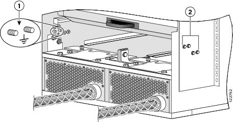
The chassis allows you to connect the central office ground system or interior equipment ground system to the bonding and grounding receptacles on the router chassis, when either a fixed or modular configuration power system is installed. Six chassis grounding points are provided at the rear (MSC) side of the chassis, as shown in the following figure. Each side of the chassis has one pair of threaded ground studs located on the inside of the chassis and two pairs of grounding receptacles located on the outside of the chassis. These ground points are also called the network equipment building system (NEBS) bonding and grounding points.
Note | These bonding and grounding receptacles satisfy the Telcordia NEBS requirements for bonding and grounding connections. |
|
1 |
NEBS bonding and grounding points (inside chassis) |
|
2 |
NEBS bonding and grounding points (outside chassis) |
To connect the chassis to a NEBS-compliant bonding and grounding system at your site, you must have the following:
- One grounding lug that has two M6 bolt holes with 0.625 inches (15.86 mm) spacing between them, and a wire receptacle large enough to accept a 6-AWG or larger multi-strand copper wire. The lug is similar to the straight type used for the DC-input power.
- Four M6 or equivalent hex-head nuts with integrated locking washers are shipped pre-installed on the inside of the chassis.
- Eight M6 or equivalent hex-head bolts with integrated locking washers are shipped pre-installed on the outside of the chassis.
Note | The chassis ground wire connectors have a torque value of 30 in.-lb (3.39 N-m). |
- Grounding wire. Although we recommend at least 6-AWG multi-strand copper wire, the actual wire diameter and length depend on your router location and site environment. This wire is not available from Cisco Systems; it is available from any commercial cable vendor. The wire should be sized according to local and national installation requirements.
 Caution | The DC Return of the Cisco CRS 8-slot chassis should remain isolated from the system frame and chassis (DC-I: Isolated DC Return). |
For additional information about NEBS, see Cisco CRS Carrier Routing System Regulatory Compliance and Safety Information.
DC Power Systems
The Cisco CRS 8-slot line card chassis can be configured with either a fixed or modular configuration DC-input power subsystem. The chassis power system provides the necessary power for chassis components. Site power requirements differ, depending on the source voltage used.
Each DC powered chassis contains either two fixed configuration PDUs or two modular configuration power shelves for 2N redundancy. A fixed configuration DC PDU connects to a DC PEM, while a modular configuration DC power shelf connects to up to four DC PMs.
- Fixed Configuration DC Power Requirements
- Fixed Configuration DC Input Power and Ground Cables
- Modular Configuration DC Power Requirements
- Modular Configuration DC Input Power Cables
Fixed Configuration DC Power Requirements
A fixed configuration DC-powered LCC contains two DC-input PDUs and two DC PEMs. Each DC PDU is connected to three DC power inputs and contains a single 7500-watt DC PEM that is field replaceable. Input DC power enters the PDU and is passed to the PEM, which provides power to the components in the chassis. Each PEM has its own circuit breaker.
In addition to the requirements described in the General Power and Grounding Requirements, DC input power requirements are as follows:
- A DC-powered chassis requires up to a maximum of 8,000 watts (8.0 kW) of DC input power when the chassis is fully loaded.
- Each DC PDU requires three DC input feeds of –48/–60 VDC (nominal). The PDU accepts input DC power in the range –40.5 to –75 VDC.
- A DC-powered
chassis requires access to the “A” and “B” power buses at the central office
(CO). This dual connectivity provides 2N power redundancy in case a power
source fails.
- One PDU should be connected to three –48/–60 VDC inputs from the central office “A” power bus.
- The other PDU should be connected to three –48/–60 VDC inputs from the “B” power bus.
- Required input
current is as follows:
- 56 amps at nominal input voltage (–48/–60 VDC).
- 66 amps at low input voltage (–40.5 VDC).
- All power connection wiring must conform to the rules and regulations in the National Electrical Code (NEC) and any local codes. In addition, make sure that the wiring conforms to any internal requirements at the installation site.
- Each DC power source must comply with the safety extra-low voltage (SELV) requirements in UL 60950-1, CSA-C22.2 No. 60950-1, EN60950-1, AS/NZS 60950, and IEC60950-1.
- A DC-powered system should be installed in a restricted access area in accordance with the National Electric Code, ANSI/NFPA 70.
- All components in the area where DC input power is accessible must be properly insulated.
- A readily accessible two-pole disconnect device must be incorporated in the fixed wiring, unless it is possible to rely on the identification of the power return conductor that is earth-grounded in the DC power system.
Fixed Configuration DC Input Power and Ground Cables
Each PDU has three pairs of double-stud terminals (RTN, –48V/–60V) for connecting DC input power. To provide 2N power redundancy, one PDU should be connected to the central office “A” power bus and the other PDU should be connected to the “B” power bus.
The requirements for the DC input power and ground connections are as follows:
- For DC input power cables, select the appropriate wire gauge based on the National Electrical Code (NEC) and local codes for 60-amp service at nominal DC input voltage (–48/–60 VDC). Three pairs of cable leads, source DC (–) and source DC return (+), are required for each PDU. These cables are available from any commercial cable vendor. All input power cables for the chassis should have the same wire gauge and cable lengths should match within 10 percent of deviation.
Each DC input power cable is terminated at the PDU by a cable lug. The cable lugs must be dual-hole, and have a 45-degree angle tongue. They must be able to fit over 1/4-inch terminal studs at 0.625-inch (15.88-mm) centers. For example, you could terminate a 2-AWG power cable with a cable lug, such as Panduit part number LCC2-14AWH-Q (Cisco part number 32-0677-01) or equivalent, as shown in this figure.
Note | Use local electrical codes for clearance requirements when using power lugs to ensure safe operation. |

Note | DC input power cables must be connected to the PDU terminal studs in the proper positive (+) and negative (–) polarity. In some cases, the DC cable leads are labeled, which is a relatively safe indication of the polarity. However, you must verify the polarity by measuring the voltage between the DC cable leads. When making the measurement, the positive (+) lead and the negative (–) lead must always match the (+) and (–) labels on the PDU. |
- An earth ground cable is required for each fixed configuration DC PDU. We recommend that you use at least 6-AWG multistrand copper wire. This wire is not available from Cisco Systems; it is available from commercial cable vendors.
The ground wire cable lug should be dual-hole, as shown in the following figure, and able to fit over M6 terminal studs at 0.625-inch (15.88-mm) centers (for example, Panduit part number LCD6-14A-L or equivalent).

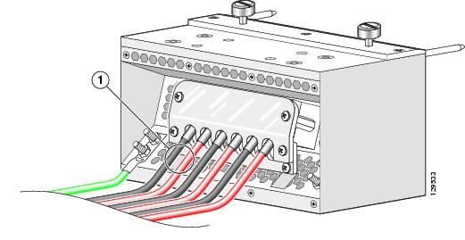
This figure shows the DC input power cables connected to the DC PDU terminal studs.
|
1 |
Each set of cables (RTN and –48V/–60V) is a single VDC input. |
Note | When wiring the fixed configuration DC PDU, be sure to attach the ground wire first (shown above on the far left side of PDU). When removing the wiring, be sure to remove the ground wire last. |
Note | In the fixed configuration DC power system, power wires have a 20 in.-lb (2.26 N-m) torque value and ground wires have a 30 in.-lb (3.39 N-m) torque value. The PDU mounting screws have a 9 in.-lb (1.04 N-m) torque value. |
The color coding of the DC input power cable leads depends on the color coding of the site DC power source. Typically, green or green and yellow indicates that the cable is a ground cable. Because there is no color code standard for the source DC wiring, you must ensure that the power cables are connected to the PDU terminal studs in the proper positive (+) and negative (–) polarity.
Caution | Although reverse polarity should not damage the DC power system, you should correct a reverse polarity condition immediately. |
Modular Configuration DC Power Requirements
A modular configuration DC-powered LCC contains two DC power shelves. Each modular configuration DC power shelf is connected to up to four DC power inputs and contains up to four DC PMs that are field replaceable.
In addition to the requirements described in the General Power and Grounding Requirements, DC input power requirements are as follows:
- A DC-powered chassis requires up to a maximum of 9,500 watts of DC input power when the chassis is fully loaded.
- Each modular configuration DC power shelf requires up to four DC input feeds of either –48 VDC (nominal), 50 A or –60 VDC (nominal), 40 A. The power shelf accepts input DC power in the range –40 to –72 VDC.
- A DC-powered
chassis requires access to the “A” and “B” power buses at the central office
(CO). This dual connectivity provides 2N power redundancy in case a power
source fails.
- One power shelf should be connected to up to four –48/–60 VDC inputs from the central office “A” power bus, depending on the number of DC PMs installed.
- The other power shelf should be connected to up to four –48/–60 VDC inputs from the “B” power bus, depending on the number of DC PMs installed.
- Required input
current is as follows:
- 50 amps at –48 VDC nominal input voltage.
- 40 amps at –60 VDC nominal input voltage
- 60 amps at low input voltage (–40 VDC).
- All power connection wiring must conform to the rules and regulations in the National Electrical Code (NEC) and any local codes. In addition, make sure that the wiring conforms to any internal requirements at the installation site.
- Each DC power source must comply with the safety extra-low voltage (SELV) requirements in UL 60950-1, CSA-C22.2 No. 60950-1, EN60950-1, AS/NZS 60950, and IEC60950-1.
- A DC-powered system should be installed in a restricted access area in accordance with the National Electric Code, ANSI/NFPA 70.
- All components in the area where DC input power is accessible must be properly insulated.
Modular Configuration DC Input Power Cables
Each power shelf contains four pairs of double-stud terminals (RTN, –48V/–60V) for connecting DC input power. To provide 2N power redundancy, one power shelf should be connected to the central office “A” power bus and the other power shelf should be connected to the “B” power bus.
The requirements for the DC input power connections are as follows:
- For DC input power cables, select the appropriate wire gauge based on the National Electrical Code (NEC) and local codes for –48 VDC (nominal), 50 A DC input voltage, or –60 VDC (nominal), 40 A DC input voltage. Up to four pairs of cable leads, source DC (–) and source DC return (+), are required for each power shelf, depending on the number of DC PMs installed. These cables are available from any commercial cable vendor. All input power cables for the chassis should have the same wire gauge and cable lengths should match within 10 percent of deviation.
- Each DC input power cable is terminated at the power shelf by a cable lug. The power supply terminal block lug opening width is 0.625 inch (15.8 mm). The terminal posts are centered 0.625 inches (15.88 mm) apart and are M6-threaded. We recommend that you use an appropriately sized 180-degree angle (straight) industry standard dual-hole, standard barrel compression lug, as shown in the 180 Degree DC Input Power Cable Lug figure, or an appropriately sized 45-degree angle industry standard 2-hole, standard barrel compression lug, as shown in the 45 Degree DC Input Power Cable Lug figure .
Note | Use local electrical codes for clearance requirements when using power lugs to ensure safe operation. |
The following figure shows the DC input power cables connected to the modular configuration DC power shelf terminal studs.

Note | In the modular configuration DC power system, the power wire connectors have a torque value of 20 in-lb (2.26 N-m). |
Note | An earth ground cable is not required for the modular configuration DC power shelf. |
AC Power Systems
The Cisco CRS 8-slot line card chassis can be configured with either a fixed or modular configuration AC-input power subsystem. The chassis power system provides the necessary power for chassis components. Site power requirements differ, depending on the source voltage used.
Each AC powered chassis contains two fixed configuration AC PDUs or two modular configuration AC power shelves for 2N redundancy. A fixed configuration AC PDU connects to an AC rectifier, while a modular configuration AC power shelf can contain up to three AC PMs.
- Fixed Configuration AC Power Requirements
- Fixed Configuration AC PDU Wiring
- Modular Configuration AC Power Requirements
- Modular Configuration AC Power Shelf Wiring
- Converting 3-Phase AC to Single-Phase AC
Fixed Configuration AC Power Requirements
A fixed configuration AC-powered LCC contains two AC power distribution units (PDUs) and two AC rectifier modules. Each AC PDU is connected to an input AC power source and holds a single 7500-watt AC rectifier. Input AC power enters the PDU and is passed to the rectifier. Here, the input AC power is converted into the 54.5 VDC used to power components in the chassis. Each AC rectifier is field replaceable and has its own circuit breaker.
Two versions of the AC PDU are available to accommodate AC input power in either the Delta or Wye configuration. Each PDU has a different Cisco part number, and ships with an AC power cord that is 14 feet (4.3 m) long.
In addition to the requirements in the General Power and Grounding Requirements, AC input power requirements are as follows:
- An AC-powered chassis (Wye or Delta) requires up to a maximum of 8,500 watts of AC input power when the chassis is fully loaded.
- Two separate and independent AC power sources are required, one for each PDU. Each PDU should be connected to a different power source to provide 2N power redundancy in case a power source fails.
- Each AC power source must provide 3-phase AC power, and have its own circuit breaker.
- AC Delta input:
- 3-phase, 200 to 240 VAC (phase-to-phase), 50 to 60 Hz.
- Input current: 30 A. The PDU is rated for 24-amp service, and accepts AC input of 30 A.
- Delta power cord has a 4-pin NEMA L15-30P plug (3 wire + protective earthing [3W+PE]). The power cord is rated for 250 VAC, 30 A, and plugs into a similarly rated NEMA L15-30R locking-type receptacle.
- AC Wye input:
- 3-phase, 200 to 240 VAC (phase-to-neutral), 50 to 60 Hz.
- Input current: 16 A (International) or 20 A (North America). The PDU is rated for 14-amp service, and accepts AC input of 16 A (International) or 20 A (North America).
- Wye power cord has a 5-pin IEC 60309 plug (3 wire + neutral + protective earthing conductor (ground wire) [3W+N+PE]). The cord is rated for 400 VAC, 16 or 20 A, and plugs into a similarly rated IEC 60309 receptacle.
- Grounding-type AC power outlet is required. The PDUs are shipped with AC power cords that have a grounding-type plug. As a safety feature, the plugs fit only a grounding-type AC power outlet.
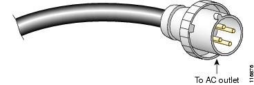
The following figures show the plugs for the AC Delta and Wye power cords.


For detailed AC power specifications, see Line Card Chassis Specifications. The following section describes the 3-phase wiring for AC Delta and Wye configurations.
Fixed Configuration AC PDU Wiring
This section contains a brief description of the 3-phase wiring for AC Delta and Wye configurations that facilities electricians should understand.
AC Delta and AC Wye are both basically 200 to 240 VAC input power:
- AC Delta 3-phase wiring is typically used in the United States, Japan, and other countries where the phase-to-neutral voltage is approximately 120 VAC and 208 VAC phase to phase.
- AC Wye 3-phase wiring is typically used in Europe and countries where each phase-to-neutral voltage is approximately 220 VAC.
AC Delta 3-Phase Wiring
The figure shows a PDU wired for AC Delta 3-phase power. As shown, input AC power is routed to three internal 2.5-kW power modules in the rectifier, where it is converted into DC power (nominal 54.5 VDC, 46 ADC) and routed to the three load zones of the chassis.
The AC Delta PDU is shipped with a 14-foot (4.3-m) AC power cord with a 4-pin L15-30P plug.

AC Wye 3-Phase Wiring
This figure shows a PDU wired for AC Wye 3-phase power. As shown, input AC power is routed to three internal 2.5-kW power modules in the rectifier, where it is converted into DC power (nominal 54.5 VDC, 46 ADC) and routed to the three load zones of the chassis.
The AC Wye PDU is shipped with a 14-foot (4.3-m) AC power cord. The power cord has a 5-pin IEC 60309 plug that is rated for 16 A (International) and 20 A (North America). It plugs into an IEC 60309 receptacle (16 or 20 A).

Modular Configuration AC Power Requirements
A modular configuration AC-powered LCC contains two AC power shelves and up to three AC PMs per power shelf.
In addition to the requirements in the General Power and Grounding Requirements section, AC input power requirements are as follows:
- An AC-powered chassis requires up to a maximum of 9,800 watts of AC input power when the chassis is fully loaded.
- Two separate and independent AC power sources are required, one for each power shelf. Each power shelf should be connected to a different power source to provide 2N power redundancy in case a power source fails.
- Each AC power source must provide single-phase AC power, and have its own circuit breaker.
- The AC power receptacles used to plug in the chassis must be the grounding type. The grounding conductors that connect to the receptacles should connect to protective earth ground at the service equipment.
- AC single-phase
input:
- Single-phase, 200 to 240 VAC nominal, 50 to 60 Hz, 16 A International and 20 A North America.
- Each AC power shelf contains three IEC-320-C22 receptacles which can accept up to three IEC-320-C21 connector female plugs, depending on how many AC PMs are installed in the shelf.
- Unlike the fixed configuration AC power system, which requires 3-phase AC Delta or AC Wye input power, the modular configuration AC power system requires single-phase AC input power. If you have 3-phase AC Delta or AC Wye at your equipment, a Cisco CRS 3-phase AC PDU will be required to convert 3-phase AC input power to single-phase AC input power for the power shelf. For further information, refer to Cisco CRS 3-Phase AC Power Distribution Unit Installation Guide.
Note | If you have a Cisco CRS 3-phase AC PDU installed, three AC PMs are required to be installed in each modular configuration AC power shelf to maintain a balanced 3-phase power load. |
For detailed modular configuration AC power specifications, see the Line Card Chassis Specifications.
Modular Configuration AC Power Shelf Wiring
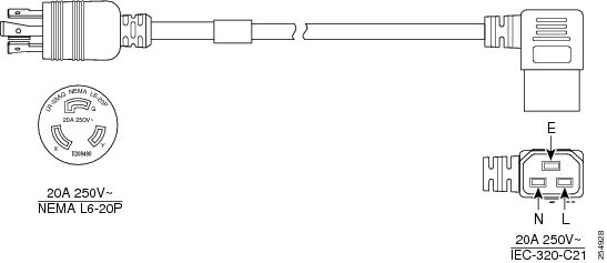
The modular configuration AC power shelf is shipped with AC power cords. Each modular configuration AC power shelf accepts up to three power cords. Each AC power cord has a different plug type, depending on locale. AC power cords are available for the following locales:
The table lists the single-phase AC-input cord power options and Cisco product numbers for the Cisco CRS 8-slot LCC with a modular configuration AC power shelf installed. Every locale listed in the table have power cord illustrations as show below.
|
Locale |
Cisco Product Number |
Plug Rating |
|---|---|---|
|
North America |
CRS-AC-CAB-NA(=) |
20 A/250 VAC |
|
Europe |
CRS-AC-CAB-EU(=) |
16 A/250 VAC |
|
United Kingdom |
CRS-AC-CAB-UK(=) |
13 A/250 VAC |
|
Italy |
CRS-AC-CAB-IT(=) |
16 A/250 VAC |
|
Australia |
CRS-AC-CAB-AU(=) |
15 A/250 VAC |


Note | The BS-1363 standard rates cord sets up to a maximum of 13 A, 250 VAC for the C-21 plug. Therefore, the building circuit breaker must be 13 A maximum. Installation of the Cisco CRS 8-slot line card chassis must follow national and local electrical codes. |


Note | The AS 3112 standard rates cord sets up to a maximum of 15 A, 250 VAC for the C-21 plug. Therefore the building circuit breaker must be 15 A maximum. Installation of the Cisco CRS 8-slot line card chassis must follow national and local electrical codes. |
Converting 3-Phase AC to Single-Phase AC
If you have 3-phase AC Delta or AC Wye input power at your equipment, a Cisco CRS 3-phase AC PDU will be required to convert 3-phase AC Delta or AC Wye input power to single-phase AC input power that connects directly to the rear of the modular configuration AC power shelf. The Cisco CRS PDU includes either an AC Delta or AC Wye power interface, and has power input and power output cords entering and exiting the box.
In addition to the requirements in the General Power and Grounding Requirements, AC input power requirements are as follows:
- Two separate and independent AC power sources are required, one for each PDU. Each PDU should be connected to a different power source to provide 2N power redundancy in case a power source fails.
- Each AC power source must provide 3-phase VAC power, and have its own circuit breaker.
- AC Delta input:
- 3-phase, 200 to 240 VAC (phase-to-phase), 50 to 60 Hz.
- Input current: 27.7 A.
- Delta input power cord has a 4-pin IEC 60309 plug (3 wire + protective earthing [3W+PE]). The power cord is rated for 250 VAC, 60 A, and plugs into a similarly rated IEC 60309 receptacle.
- Each single PDU has three single phase output cords, each with a 90 degree IEC-320-C21 plug that plugs into a IEC-320-C22 inlet on the rear of the modular configuration AC power shelf.
- AC Wye input:
- 3-phase, 200 to 240 VAC (phase-to-neutral), 50 to 60 Hz.
- Input current: 16 A (International) or 20 A (North America). The PDU is rated for 16-amp service.
- Wye power cord has a 5-pin IEC 60309 plug (3 wire + neutral + protective earthing conductor (ground wire) [3W+N+PE]). The cord is rated for 415 VAC, 16 A, and plugs into a similarly rated IEC 60309 receptacle.
- Grounding-type AC power outlet is required. The PDUs are shipped with AC power cords that have a grounding-type plug. As a safety feature, the plugs fit only a grounding-type AC power outlet.
The following figures show the plugs for the power cords on the AC Delta and Wye PDUs.
For detailed Cisco CRS Power Distribution Unit AC power specifications, see the Cisco CRS 3-Phase AC Power Distribution Unit Installation Guide. .
Chassis Airflow
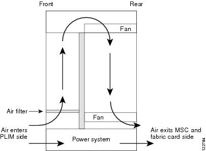
The Cisco CRS 8-slot line card chassis has two fan trays, with four fans each, that cool the chassis card cages. Cool air flows in at the bottom front of the chassis and flows through the chassis card cages and through the fans in the fan trays before being exhausted through the bottom rear of the chassis, as shown in the figure below.
In addition, each fixed configuration AC or DC power module at the bottom of the chassis has self-contained fans that pull in cool air from the front of the chassis and exhaust warm air out the rear.
A replaceable air filter is located on the front of the chassis below the PLIM card cage. Each fixed configuration power module also has a replaceable air filter that attaches to the module at the front side of the chassis. How often you should replace the air filters depends on the facility environment.
In a dirty environment, or when you start getting frequent temperature alarms, you should always check the intake grills for debris, and then check the air filters to see if they need to be replaced.
Note | We recommend that you check the air filters once a month. Replace a filter when you notice a significant amount of dust. |
The 8-slot LCC airflow volumes are as follows:
Facility Cooling Requirements
The 8-slot line card chassis dissipates considerable power that generates much heat. In large configurations, additional air cooling is required to maintain correct operating temperatures. The room air must be cooled by external cooling units that are installed as part of the routing system.
>Heat dissipation and external cooling requirements for the 8-slot line card chassis are as follows:
- Heat dissipation (fixed configuration): 28,720 BTUs per hour
- Heat dissipation (modular configuration): 32,570 BTUs per hour
- External cooling requirements: 2.3 tons
To ensure that the site provides the proper air circulation for the system:
- Make certain that the site is as dust free as possible. Dusty environments can clog the air filter or power supply intake vents, reducing the cooling airflow through the system.
- Allow sufficient airflow by maintaining a minimum of 6 inches (15.2 cm) of clearance at both the inlet and exhaust openings on the chassis and the fixed configuration power modules. If airflow is blocked or restricted, or if inlet air is too warm, an over-temperature condition can occur. Under extreme conditions, the environmental monitoring system shuts down the power to protect the routing system components.
 Feedback