Cisco CRS Carrier Routing System Multishelf System Description
Bias-Free Language
The documentation set for this product strives to use bias-free language. For the purposes of this documentation set, bias-free is defined as language that does not imply discrimination based on age, disability, gender, racial identity, ethnic identity, sexual orientation, socioeconomic status, and intersectionality. Exceptions may be present in the documentation due to language that is hardcoded in the user interfaces of the product software, language used based on RFP documentation, or language that is used by a referenced third-party product. Learn more about how Cisco is using Inclusive Language.
- Updated:
- December 1, 2016
Chapter: Shelf Controller Gigabit Ethernet Card
Shelf Controller Gigabit Ethernet Card
This chapter describes the shelf controller card (CRS-FCC-SC-22GE and CRS-FCC-SC-22GE-B) for the fabric card chassis (FCC). It includes these sections:
The SCGE card described in this chapter uses a Class 1 laser. These warnings apply to the SCGE card.
Class 1 Laser Product. Statement 113
Because invisible radiation may be emitted from the aperture of the port when no fiber cable is connected, avoid exposure to radiation and do not stare into open apertures. Statement 125
Shelf Controller Card Functional Overview
The Shelf Controller card is the local system management node for a FCC.
The Shelf Controller card provides system initialization, debugging, and low-level hardware control for all SFCs in an FCC and other system cards. The card includes front-panel ports and an alphanumeric LED display. Communication within the chassis takes place over a redundant set of backplane Fast Ethernet (FE) links controlled by the SCGE card. The SCGE card also controls power up, initialization, SFCs, the optical interface module LED (OIM-LED) card, alarms, power supplies, and fans in an FCC. It also includes the 48-V soft-start circuitry for the fan tray.
 Note | By default, two Shelf Controller cards are installed in an FCC to provide redundancy. Throughout the remainder of this chapter, these cards are identified as active and standby cards. |
The Shelf Controller card:
- Provides the power-on boot of the SCGE CPU and the system management ports
- Determines control of the chassis (active or standby) with the other SCGE card in the chassis
- Provides 22 GE ports for the external system management communications across the chassis
In active mode, the SCGE:
- Downloads Ethernet MAC addresses from the backplane erasable programmable read-only memory (EPROM) and assigns them to all cards in the chassis
- Serves as the FE switch for the intrachassis system management network
- On command from the system management network, starts up and monitors power supplies, chassis fans, and thermal sensors
- On command from the system management network, downloads software images to the SFCs in the chassis, starts up card power supplies, and starts and resets card processors
- Sends alarms and resets, or shuts down portions of the chassis hardware in abnormal or dangerous conditions within the chassis
- Keeps a log of SCGE card and chassis activity on nonvolatile memory and places core dumps onto an internal hard disk
- In case of a timeout, initiates self-reset or rearbitration for chassis ownership
- Controls the fan speed
In standby mode, the SCGE card:
- Periodically tests the FE links to all chassis hardware
- Keeps local state information synchronized
- Rearbitrates for chassis ownership if the active card releases ownership
The FCC holds up to 24 SFCs, 2 SCGE cards, 2 fan trays, 24 optical interface module (OIM) cards, 2 OIM-LED cards, 2 alarm modules, and 2 AC or DC power shelves. Except for the SCGE cards, OIM cards, and fan trays, each of these components has its own service processor (SP) with two backplane FE links to the SCGE cards.
In addition, the two SCGE cards have one FE link between them, and each SCGE card has one backplane FE link routed back to itself. The 48-V soft-start circuit of the fan tray is part of the SCGE card. The SCGE card controls the fan speed and monitors the status of the fan trays through four I2C buses, with two buses going to each fan tray.
22-Port SCGE Card Overview
This section describes the 22-port SCGE card and its components.
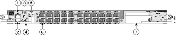
This figure shows the front panel of the CRS-FCC-SC-22GE card in a horizontal view.
|
1 |
RJ-45 auxiliary (AUX) port |
5 |
Alphanumeric LEDs |
|
2 |
RJ-45 CONSOLE port |
6 |
Gigabit Ethernet interface |
|
3 |
STATUS LED |
7 |
PCMCIA card slots |
|
4 |
PRIMARY LED |
|
|
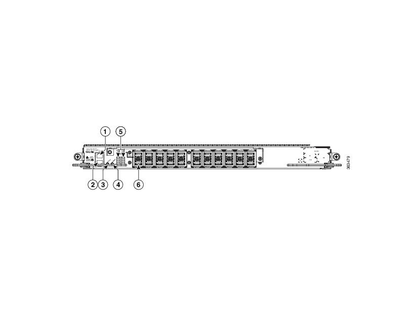
This figure shows the front panel of the CRS-FCC-SC-22GE-B card in a horizontal view.
|
1 |
RJ-45 auxiliary (AUX) port |
4 |
PRIMARY LED |
|
2 |
RJ-45 CONSOLE port |
5 |
Alphanumeric LEDs |
|
3 |
STATUS LED |
6 |
Gigabit Ethernet interface |
Note | The shelf controller cards are located in the first slot to the right of the upper and lower card cages. They are identified as SCGE0 and SCGE1. |
Front-Panel Interface
The front panel of the 22-port SCGE card includes various components that interface with the user. This section describes the front-panel interfaces.
Asynchronous Serial Ports
The 22-port SCGE card has two asynchronous serial ports, the CONSOLE and auxiliary (AUX) ports. These ports allow you to connect external serial devices so you can monitor and manage the system. Both ports use RJ-45 receptacles.
- Console port—Provides a data terminal equipment (DTE) interface for connecting a console terminal.
- Auxiliary (AUX) port—Provides a data terminal equipment (DTE) interface and supports flow control. The port is often used to connect a modem, a channel service unit (CSU), or other optional equipment for Telnet management.
LED Displays
The 22-port SCGE card includes these LED displays:
- Alphanumeric LEDs—Displays Cisco IOS XR software status and error messages.
- PRIMARY LED—When lit, this LED indicates whether the 22-port SCGE card is operating as the active SCGE card in the chassis, or not.
-
STATUS LED—Indicates the status of the 22-port SCGE cards relative to power and thermal conditions. A green LED indicates that the card is operating normally. A flashing yellow LED indicates that one of these abnormal conditions has occurred:
- One of the power supplies is operating at 10 percent below nominal specifications.
- The temperature at one of the three thermal sensors exceeds 90 degrees Celsius.
- ENABLE and LINK/ACTIVE LED—Each port on the CRS-FCC-SC-22GE-B card has two LEDs, one bicolor and one single color. This table describes the port LEDs.
|
Enabled LED |
Link/Active LED |
Description |
|---|---|---|
|
Blinking green |
Of |
The port is booting or running diagnostics. |
|
Steady Amber |
Off |
The port is faulty. |
|
Off |
Off |
Port is administratively shut down. |
|
Steady green |
Off |
The port is enabled but the link is not connected. |
|
Steady green |
On |
The port is enabled and the link is connected but there is no activity. |
|
Steady green |
Blinking |
The port is active. The link is connected and there is activity. |
The 22-port SCGE card includes a safety shutdown circuit that powers down all voltages except the 5-V housekeeping voltage. When an abnormal condition is sensed, the STATUS LED on the front panel flashes yellow. Ten seconds later, the shutdown is triggered and power to the card is shut down until the card is reset. After the card powers down, it must be power-cycled by removing it from the chassis or powering down the entire chassis. This mechanism requires that the 5-V housekeeping voltage be functioning correctly.
Gigabit Ethernet Interface
The 22-port SCGE card includes a 22-port GE interface (1000BASE-LX) for connection to the control network that links all LCCs and FCCs. See the Cisco CRS Carrier Routing System Multishelf System Interconnection and Cabling Guide for complete multishelf system cabling information.
PCMCIA PC Cards
The 22-port SCGE card (CRS-FCC-SC-22GE only) includes one removable and one fixed PC Card (PCMCIA Type I / II) for local storage needs. The removable, external PC Card facilitates image files of up to 1 GB. The nonremovable, internal PC Card also facilitates image files of up to 1 GB. However, this card is for Cisco use only and is not accessible to users.
 Feedback