- Preface
- Installation Roadmap Overview
- Cisco CRS 16-Slot Line Card Chassis Enhanced Router
- Installing Power Components
- Installing and Removing Air Circulation Components
- Installing Exterior Cosmetic Components
- Installing Line Cards, PLIMs, and Associated Components
- Removing Chassis Components
- Upgrading Chassis Components
- Cisco CRS 16-Slot EC Line Card Chassis Specifications
- Product IDs
Installing Exterior
Cosmetic Components
This chapter provides instructions on how to install the Cisco CRS Enhanced 16-slot line card chassis exterior cosmetic components.
This chapter presents the following topics:
- Information About Exterior Cosmetic Components
- Installing the Front (PLIM) Side Exterior Cosmetic Components
- Installing the Rear (MSC) Side Cosmetic Components
- Attaching the Upper Rear Air Grille and Rear Kick Plate Without Vertical Troughs
Information About Exterior Cosmetic Components
This section contains some general information about the exterior cosmetic components.
The Cisco CRS Series enhanced 16-slot line card chassis is shipped with exterior cosmetic components for the front (PLIM) side and rear (MSC) side of the chassis.
 Note | Some exterior cosmetic components, such as the cable pass-through accessory plates, are not required to be installed. |
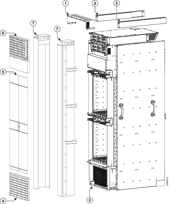
This figure shows the default exterior cosmetic components for the front (PLIM) side of a Cisco CRS Series enhanced 16-slot line card chassis.

|
1 |
Upper grille support |
5 |
Doors |
|
2 |
Unistruts |
6 |
Upper grille |
|
3 |
Bracket for lower grille |
7 |
Vertical cable troughs |
|
4 |
Lower grille |
|
|
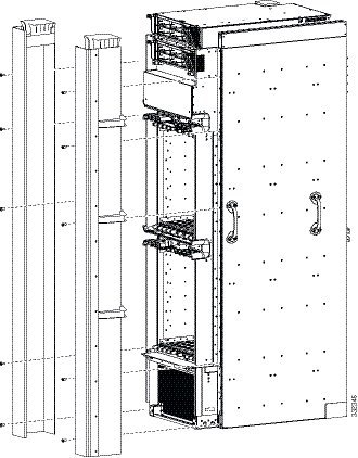
This figure shows the exterior cosmetic components for the front (PLIM) side of a Cisco CRS Series enhanced 16-slot line card chassis installed as part of a wide duct system.
|
1 |
Upper grille support |
5 |
Doors |
|
2 |
Unistruts |
6 |
Upper grille |
|
3 |
Bracket for lower grille |
7 |
Wide vertical cable troughs |
|
4 |
Lower grille |
|
|
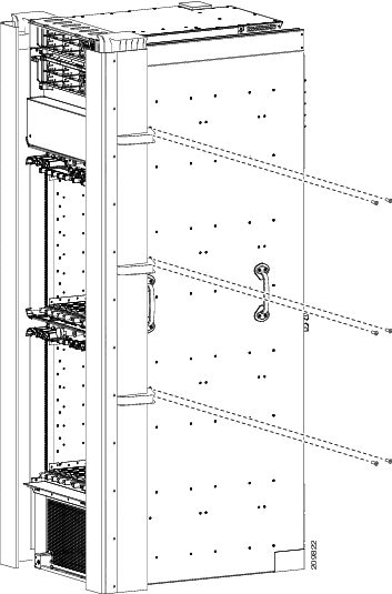
This figure shows the exterior cosmetic components for the rear (MSC) side of a Cisco CRS Series enhanced 16-slot line card chassis.

|
1 |
Vertical cable trough |
4 |
Doors |
|
2 |
Bracket for optional rear kick panel |
5 |
Upper air grille |
|
3 |
Rear kick panel (optional, orderable separately) |
|
|
Installing the Front (PLIM) Side Exterior Cosmetic Components
This section describes how to install the default front (PLIM) side exterior cosmetic components (Figure 1) on the Cisco CRS Series enhanced 16-slot line card chassis.
Note | While it is possible to install the various exterior components on the Cisco CRS Series enhanced 16-slot line card chassis in a different order, it is easier to install them in the order outlined in this section. |
The lower grille screen and frame assembly are shipped pre-installed in the chassis. The upper grille support is not shipped pre-installed on the chassis but must be installed before the power shelves are installed in the chassis. For more information, see theInstalling the Upper Grille Support
This section describes how to perform the following tasks:
Prerequisites
Before performing this task, you must first unpack and secure the chassis. See the Cisco CRS Carrier Routing System 16-Slot Line Card Chassis Unpacking, Moving, and Securing Guide.
The upper grille support should already be installed at the top of the chassis. See the Installing the Upper Grille Support for more information.
Required Tools and Equipment
You need the following tools and parts to perform this task:
- 8-in. long number 1 Phillips screwdriver—magnetic head preferable, bit size #1
- 3/8-in. drive ratchet wrench
- Default vertical cable troughs (Cisco product number 800–35625–xx [right], 800–35644–xx [left])
- Optional wide vertical cable troughs (Cisco product number 800–36457–xx [right], 800–36456–xx [left])
- Optional cable pass-through accessory kit (Cisco product number CRS–LCC–CM–COVER), used with default cosmetics
- Upper grille (Cisco product number 800–35465–xx)
- Lower grille (Cisco product number 800–35466–xx)
- Exterior doors kit (Cisco product number CRS–16–DOORS–F)
Steps
To install front (PLIM) side exterior cosmetic components, perform the following steps:
1. Unpack all cosmetic parts to prepare for installation.
2. (Attaching the Default Front Vertical Cable Troughs) Attach the vertical cable troughs—one right and one left—to the front (PLIM) side of the chassis (see Installing the Front Vertical Cable Troughs figure below):
3. (Installing the Cable Pass-through Accessory Plates (Optional)—Default Cable Trough Only) Remove the blank plates by unscrewing the four screws on each one.
4. Attach the inner cut-out plates using the four screws provided. See the Cut-Out Plates figure.
5. Attach the outer cut-out plate using the four screws provided.
6. (Attaching the Optional Wide Front Vertical Cable Troughs (Optional Trough)). Attach the vertical cable troughs—one right and one left—to the front (PLIM) side of the chassis (see Installing the Front Vertical Cable Troughs above):
7. (Installing the Upper Grille) Attach the upper grille by carefully inserting the four tabs on the grille into the appropriate hook hanger brackets on the top of the upper grille support (see below figure).
8. Press the grille and bezel firmly against the chassis until it snaps onto the ball stud snaps.
9. (Attaching the Lower Grille) Attach the lower grille by carefully inserting the tabs on the grille into the brackets on the bottom of the inlet grille frame.
10. Press the lower grille firmly until it snaps onto the ball stud snaps.
11. (Attaching the Front Exterior Doors) Orient the doors so that the slot on the metal part in the middle of the doors is lined up with the tab on the vertical cable trough. The door will then drop into position. See the below figure.
12. Insert the screws into the appropriate screw holes in the doors, and use the screwdriver to tighten fully. There are 11 M4x8 screws on each side for the metal sections of the doors and six M4x8 screws on each side for the plexiglass section of the door.
13. Ensure that the doors are properly aligned.
14. For wide duct installations (see Door Adjustments for Wide Trough Installation figure below):
DETAILED STEPS


Installing the Rear (MSC) Side Cosmetic Components
This section describes how to install the rear (MSC) side exterior cosmetic components on the Cisco CRS Series enhanced 16-slot line card chassis. While it is possible to install the various exterior components on the chassis in a different order, it is easier to install them in the order outlined in this section. Figure 3 shows the exterior cosmetics for the rear (MSC) side of a Cisco CRS Series enhanced 16-slot line card chassis.
The midchassis cable management bracket and rear door strike tube are shipped pre-installed on the chassis.
This section contains the following procedures:
Note | For instructions on installing the rear cosmetics if the vertical trough is not used, see Attaching the Upper Rear Air Grille and Rear Kick Plate Without Vertical Troughs |
Prerequisites
Before performing these tasks, you must first unpack and secure the chassis. See Cisco CRS Carrier Routing System 16-Slot Line Card Chassis Unpacking, Moving, and Securing Guide.
Required Tools and Equipment
You need the following tools and parts to perform this task:
- 8-in. long number 1 Phillips screwdriver—magnetic head preferable #1
- Rear vertical cable troughs (included in CRS-16-REAR-CM)
- Rear kick plate (included in CRS-16-REAR-CM)
- Upper air grille (CRS–16–REAR–GRL)
- Rear doors (CRS–16–DOORS–R)
- Upper rear air grille with mounting brackets (CRS-16-REAR-GRL), only if vertical troughs are not used
- Rear kick plate with mounting brackets (CRS-16-KP-REAR), only if vertical troughs are not used
Steps
To install the rear (MSC) exterior cosmetic components, perform the following steps:
1. Unpack all cosmetic parts to prepare for installation.
2. (Attaching the Rear Vertical Cable Troughs) Before you attach the left and right vertical cable troughs, if the verticals h ave L-brackets, they will need to be removed so that they do not interfere with the air deflector. See below figure.
3. Attach the rear vertical cable troughs—one left and one right—to the rear of the chassis (see the figure below) by inserting the 10 M4x14-mm pan head screws (five on each side) and using the screwdriver to turn the screws clockwise to attach the cable troughs firmly to the chassis. (You might need to use a ladder to reach the upper screws.)
4. (Attaching the Upper Rear Air Grille) Follow these steps if you are using the vertical troughs. To install the upper rear air grille without the vertical troughs, see the Attaching the Upper Rear Air Grille and Rear Kick Plate Without Vertical Troughs. Attach the upper grille by carefully hooking the hanger brackets that are on top of the grille over the hook supports that are on top of the vertical cable troughs (see below figure).
5. Press the upper rear air grille firmly until its ball studs snap onto the ball stud retainers.
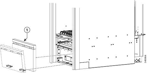
6. (Attaching the Rear Kick Plate) Carefully slot the tabs on the bottom of the rear kick plate into the brackets on the chassis (see below figure).
7. To secure the top fasteners, firmly press the top edge of the rear kick plate against the chassis until it snaps onto the ball stud snaps.
8. (Installing the Rear Doors) Orient the doors so that the slot on the metal part in the middle of the doors is lined up with the tab on the vertical cable trough. The door will then drop into position. See figure below.
9. Insert the screws into the appropriate screw holes in the doors, and use the screwdriver to tighten fully. There are 10 M4x8 screws on each side for the metal sections of the doors and six M4x8 screws on each side for the plexiglass section of the door.
10. Ensure that the doors are properly aligned.
DETAILED STEPS
| Step 1 | Unpack all cosmetic parts to prepare for installation. | ||||
| Step 2 | (Attaching the Rear Vertical Cable Troughs) Before you attach the left and right vertical cable troughs, if the verticals h ave L-brackets, they will need to be removed so that they do not interfere with the air deflector. See below figure.
 | ||||
| Step 3 | Attach the rear vertical cable troughs—one left and one right—to the rear of the chassis (see the figure below) by inserting the 10 M4x14-mm pan head screws (five on each side) and using the screwdriver to turn the screws clockwise to attach the cable troughs firmly to the chassis. (You might need to use a ladder to reach the upper screws.)
 | ||||
| Step 4 | (Attaching the Upper Rear Air Grille) Follow these steps if you are using the vertical troughs. To install the upper rear air grille without the vertical troughs, see the Attaching the Upper Rear Air Grille and Rear Kick Plate Without Vertical Troughs. Attach the upper grille by carefully hooking the hanger brackets that are on top of the grille over the hook supports that are on top of the vertical cable troughs (see below figure).
 | ||||
| Step 5 | Press the upper rear air grille firmly until its ball studs snap onto the ball stud retainers. | ||||
| Step 6 | (Attaching the Rear Kick Plate) Carefully slot the tabs on the bottom of the rear kick plate into the brackets on the chassis (see below figure).
| ||||
| Step 7 | To secure the top fasteners, firmly press the top edge of the rear kick plate against the chassis until it snaps onto the ball stud snaps. | ||||
| Step 8 | (Installing the Rear Doors) Orient the doors so that the slot on the metal part in the middle of the doors is lined up with the tab on the vertical cable trough. The door will then drop into position. See figure below.
 | ||||
| Step 9 |
Insert the screws into the appropriate screw holes in the doors, and use the screwdriver to tighten fully. There are 10 M4x8 screws on each side for the metal sections of the doors and six M4x8 screws on each side for the plexiglass section of the door.
| ||||
| Step 10 |
Ensure that the doors are properly aligned.
|
Attaching the Upper Rear Air Grille and Rear Kick Plate Without Vertical Troughs
Use the procedures in this section to install the upper rear air grille (CRS-16-REAR-GRL) and rear kick plate (CRS-16-KP-REAR) if you are not using the vertical troughs. If you are using the vertical troughs, see the procedure in the Installing the Rear (MSC) Side Cosmetic Components.
Note | Because the upper rear air grille must be installed at the top of the chassis, it is easier to stand on a ladder while installing it. |
Note | Ensure cables are dressed correctly to ensure enough clearance to install the upper air grille. |
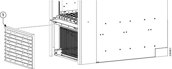
1. To attach the upper rear air grille, hang the grille on the inside grille supports.
2. Pivot to the closed position.
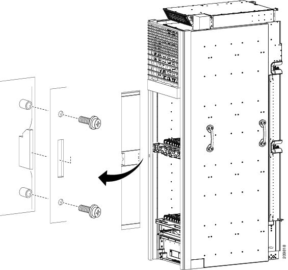
3. To attach the rear kick plate, first attach the two brackets provided with the kick plate and fasten them using the captive screws that are included (see figure below).
4. Carefully slot the tabs on the bottom of the rear kick plate into the brackets on the chassis (see figure below).
5. To secure the top fasteners, firmly press the top edge of the rear kick plate against the chassis until it snaps onto the ball stud snaps.
DETAILED STEPS
| Step 1 |
To attach the upper rear air grille, hang the grille on the inside grille supports.
 | ||
| Step 2 | Pivot to the closed position. | ||
| Step 3 | To attach the rear kick plate, first attach the two brackets provided with the kick plate and fasten them using the captive screws that are included (see figure below).

| ||
| Step 4 | Carefully slot the tabs on the bottom of the rear kick plate into the brackets on the chassis (see figure below).

| ||
| Step 5 | To secure the top fasteners, firmly press the top edge of the rear kick plate against the chassis until it snaps onto the ball stud snaps. |
 Feedback