Configuring Ethernet OAM

This module describes the configuration of Ethernet Operations, Administration, and Maintenance (OAM) .

Feature History for Configuring Ethernet OAM

Release

Modification

Release 6.1.1

Support for the following features was introduced:

  • Ethernet CFM

Release 6.3.1

Support for the following feature was introduced:

  • Unidirectional Link Detection Protocol

Information About Configuring Ethernet OAM

To configure Ethernet OAM, you should understand the following concepts:

Ethernet Link OAM

Ethernet as a Metro Area Network (MAN) or a Wide Area Network (WAN) technology benefits greatly from the implementation of Operations, Administration and Maintenance (OAM) features. Ethernet link OAM features allow Service Providers to monitor the quality of the connections on a MAN or WAN. Service providers can monitor specific events, . Ethernet link OAM operates on a single, physical link and it can be configured to monitor either side or both sides of that link.

Ethernet link OAM can be configured in the following ways:

  • A Link OAM profile can be configured, and this profile can be used to set the parameters for multiple interfaces.

  • Link OAM can be configured directly on an interface.

    When an interface is also using a link OAM profile, specific parameters that are set in the profile can be overridden by configuring a different value directly on the interface.

An Ethernet Link OAM profile simplifies the process of configuring EOAM features on multiple interfaces. An Ethernet OAM profile, and all of its features, can be referenced by other interfaces, allowing other interfaces to inherit the features of that Ethernet OAM profile.

Individual Ethernet link OAM features can be configured on individual interfaces without being part of a profile. In these cases, the individually configured features always override the features in the profile.

The preferred method of configuring custom EOAM settings is to create an EOAM profile in Ethernet configuration mode and then attach it to an individual interface or to multiple interfaces.

When an EOAM packet is received on any one of the AC interfaces on which EOAM is not configured, the AC interface multicasts the received EOAM packets to other AC interfaces that are part of EVPN-BD to reach the peer. When an EOAM is enabled on the bundle member in the peer, it punts the packet to the CPU in the peer. Also, the EOAM flaps the bundle member as the local or remote Key of the received EOAM does not match.

These standard Ethernet Link OAM features are supported on the router:

EFD

Ethernet Fault Detection (EFD) is a mechanism that allows Ethernet OAM protocols, such as CFM, to control the line protocol state of an interface.

Unlike many other interface types, Ethernet interfaces do not have a line protocol, whose state is independent from that of the interface. For Ethernet interfaces, this role is handled by the physical-layer Ethernet protocol itself, and therefore if the interface is physically up, then it is available and traffic can flow.

EFD changes this to allow CFM to act as the line protocol for Ethernet interfaces. This allows CFM to control the interface state so that if a CFM defect (such as AIS or loss of continuity) is detected with an expected peer MEP, the interface can be shut down. This not only stops traffic flow, but also triggers actions in any higher-level protocols to route around the problem. For example, in the case of Layer 2 interfaces, the MAC table would be cleared and MSTP would reconverge. For Layer 3 interfaces, the ARP cache would be cleared and potentially the IGP would reconverge.


Note


EFD can only be used for down MEPs. When EFD is used to shut down the interface, the CFM frames continue to flow. This allows CFM to detect when the problem has been resolved, and thus bring the interface backup automatically.


This figure shows CFM detection of an error on one of its sessions EFD signaling an error to the corresponding MAC layer for the interface. This triggers the MAC to go to a down state, which further triggers all higher level protocols (Layer 2 pseudowires, IP protocols, and so on) to go down and also trigger a reconvergence where possible. As soon as CFM detects there is no longer any error, it can signal to EFD and all protocols will once again go active.

Figure 1. CFM Error Detection and EFD Trigger

Ethernet CFM

Ethernet Connectivity Fault Management (CFM) is a service-level OAM protocol that provides tools for monitoring and troubleshooting end-to-end Ethernet services per VLAN. This includes proactive connectivity monitoring, fault verification, and fault isolation. CFM uses standard Ethernet frames and can be run on any physical media that is capable of transporting Ethernet service frames. Unlike most other Ethernet protocols which are restricted to a single physical link, CFM frames can transmit across the entire end-to-end Ethernet network.

CFM is defined in two standards:

  • IEEE 802.1ag—Defines the core features of the CFM protocol.

  • ITU-T Y.1731—Redefines, but maintains compatibility with the features of IEEE 802.1ag, and defines some additional features.

Ethernet CFM supports these functions of ITU-T Y.1731:

  • ETH-CC, ETH-RDI, ETH-LB, ETH-LT—These are equivalent to the corresponding features defined in IEEE 802.1ag.


    Note


    The Linktrace responder procedures defined in IEEE 802.1ag are used rather than the procedures defined in Y.1731; however, these are interoperable.


  • ETH-AIS—The reception of ETH-LCK messages is also supported.

Ethernet CFM is also supported on subinterfaces. CFM provides immediate update if there is any drop in the connection links between any or all of the devices connected in a network at the subinterface level. To support Ethernet CFM on subinterfaces, the interface {HundredGigE | TenGigE | GigE | Bundle-Ether} interface-path-id.subinterface command is updated to include the subinterface path ID. For more information on the configuration, see Configuring CFM MEPs section.


Note


In Cisco IOS XR Release 6.3.1, the CFM on subinterfaces is supported only on Cisco NCS 5001 and Cisco NCS 5002 Routers, and not supported on Cisco NCS 5011 Routers.


To understand how the CFM maintenance model works, you need to understand these concepts and features:

Maintenance Domains

A maintenance domain describes a management space for the purpose of managing and administering a network. A domain is owned and operated by a single entity and defined by the set of interfaces internal to it and at its boundary, as shown in this figure.

Figure 2. CFM Maintenance Domain

A maintenance domain is defined by the bridge ports that are provisioned within it. Domains are assigned maintenance levels, in the range of 0 to 7, by the administrator. The level of the domain is useful in defining the hierarchical relationships of multiple domains.

CFM maintenance domains allow different organizations to use CFM in the same network, but independently. For example, consider a service provider who offers a service to a customer, and to provide that service, they use two other operators in segments of the network. In this environment, CFM can be used in the following ways:

  • The customer can use CFM between their CE devices, to verify and manage connectivity across the whole network.

  • The service provider can use CFM between their PE devices, to verify and manage the services they are providing.

  • Each operator can use CFM within their operator network, to verify and manage connectivity within their network.

Each organization uses a different CFM maintenance domain.

This figure shows an example of the different levels of maintenance domains in a network.


Note


In CFM diagrams, the conventions are that triangles represent MEPs, pointing in the direction that the MEP sends CFM frames, and circles represent MIPs.

Figure 2. Different CFM Maintenance Domains Across a Network

To ensure that the CFM frames for each domain do not interfere with each other, each domain is assigned a maintenance level, between 0 and 7. Where domains are nested, as in this example, the encompassing domain must have a higher level than the domain it encloses. In this case, the domain levels must be negotiated between the organizations involved. The maintenance level is carried in all CFM frames that relate to that domain.

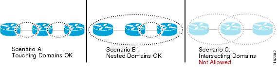
CFM maintenance domains may touch or nest, but cannot intersect. This figure illustrates the supported structure for touching and nested domains, and the unsupported intersection of domains.

Services

A CFM service allows an organization to partition its CFM maintenance domain, according to the connectivity within the network. For example, if the network is divided into a number of virtual LANs (VLANs), a CFM service is created for each of these. CFM can then operate independently in each service. It is important that the CFM services match the network topology, so that CFM frames relating to one service cannot be received in a different service. For example, a service provider may use a separate CFM service for each of their customers, to verify and manage connectivity between that customer's end points.

A CFM service is always associated with the maintenance domain that it operates within, and therefore with that domain's maintenance level. All CFM frames relating to the service carry the maintenance level of the corresponding domain.


Note


CFM Services are referred to as Maintenance Associations in IEEE 802.1ag and as Maintenance Entity Groups in ITU-T Y.1731.


Maintenance Points

A CFM Maintenance Point (MP) is an instance of a particular CFM service on a specific interface. CFM only operates on an interface if there is a CFM maintenance point on the interface; otherwise, CFM frames are forwarded transparently through the interface.

A maintenance point is always associated with a particular CFM service, and therefore with a particular maintenance domain at a particular level. Maintenance points generally only process CFM frames at the same level as their associated maintenance domain. Frames at a higher maintenance level are always forwarded transparently, while frames at a lower maintenance level are normally dropped. This helps enforce the maintenance domain hierarchy, and ensures that CFM frames for a particular domain cannot leak out beyond the boundary of the domain.

There are two types of MP:

  • Maintenance End Points (MEPs)—Created at the edge of the domain. Maintenance end points (MEPs) are members of a particular service within a domain and are responsible for sourcing and sinking CFM frames. They periodically transmit continuity check messages and receive similar messages from other MEPs within their domain. They also transmit traceroute and loopback messages at the request of the administrator. MEPs are responsible for confining CFM messages within the domain.

  • Maintenance Intermediate Points (MIPs)—Created in the middle of the domain. Unlike MEPS, MIPs do allow CFM frames at their own level to be forwarded.

MIP Creation

Unlike MEPs, MIPs are not explicitly configured on each interface. MIPs are created automatically according to the algorithm specified in the CFM 802.1ag standard. The algorithm, in brief, operates as follows for each interface:

  • The bridge-domain or cross-connect for the interface is found, and all services associated with that bridge-domain or cross-connect are considered for MIP auto-creation.

  • The level of the highest-level MEP on the interface is found. From among the services considered above, the service in the domain with the lowest level that is higher than the highest MEP level is selected. If there are no MEPs on the interface, the service in the domain with the lowest level is selected.

  • The MIP auto-creation configuration (mip auto-create command) for the selected service is examined to determine whether a MIP should be created.


    Note


    Configuring a MIP auto-creation policy for a service does not guarantee that a MIP will automatically be created for that service. The policy is only considered if that service is selected by the algorithm first.


MEP and CFM Processing Overview

The boundary of a domain is an interface, rather than a bridge or host. Therefore, MEPs can be sub-divided into two categories:

  • Down MEPs—Send CFM frames from the interface where they are configured, and process CFM frames received on that interface. Down MEPs transmit AIS messages upward (toward the cross-connect).

  • Up MEPs—Send frames into the bridge relay function, as if they had been received on the interface where the MEP is configured. They process CFM frames that have been received on other interfaces, and have been switched through the bridge relay function as if they are going to be sent out of the interface where the MEP is configured. Up MEPs transmit AIS messages downward (toward the wire). However, AIS packets are only sent when there is a MIP configured on the same interface as the MEP and at the level of the MIP.


Note


  • The terms Down MEP and Up MEP are defined in the IEEE 802.1ag and ITU-T Y.1731 standards, and refer to the direction that CFM frames are sent from the MEP. The terms should not be confused with the operational status of the MEP.

  • The router only supports the "Down MEP level < Up MEP level" configuration.


This figure illustrates the monitored areas for Down and Up MEPs.

Figure 4. Monitored Areas for Down and Up MEPs

This figure shows maintenance points at different levels. Because domains are allowed to nest but not intersect (see ), a MEP at a low level always corresponds with a MEP or MIP at a higher level. In addition, only a single MIP is allowed on any interface—this is generally created in the lowest domain that exists at the interface and that does not have a MEP.

MIPs and Up MEPs can only exist on switched (Layer 2) interfaces, because they send and receive frames from the bridge relay function. Down MEPs can be created on switched (Layer 2) interfaces.

MEPs continue to operate normally if the interface they are created on is blocked by the Spanning Tree Protocol (STP); that is, CFM frames at the level of the MEP continue to be sent and received, according to the direction of the MEP. MEPs never allow CFM frames at the level of the MEP to be forwarded, so the STP block is maintained.

MIPs also continue to receive CFM frames at their level if the interface is STP blocked, and can respond to any received frames. However, MIPs do not allow CFM frames at the level of the MIP to be forwarded if the interface is blocked.


Note


A separate set of CFM maintenance levels is created every time a VLAN tag is pushed onto the frame. Therefore, if CFM frames are received on an interface which pushes an additional tag, so as to “tunnel” the frames over part of the network, the CFM frames will not be processed by any MPs within the tunnel, even if they are at the same level. For example, if a CFM MP is created on an interface with an encapsulation that matches a single VLAN tag, any CFM frames that are received at the interface that have two VLAN tags will be forwarded transparently, regardless of the CFM level.


CFM Protocol Messages

The CFM protocol consists of a number of different message types, with different purposes. All CFM messages use the CFM EtherType, and carry the CFM maintenance level for the domain to which they apply.

This section describes the following CFM messages:

Continuity Check (IEEE 802.1ag and ITU-T Y.1731)

Continuity Check Messages (CCMs) are “heartbeat” messages exchanged periodically between all the MEPs in a service. Each MEP sends out multicast CCMs, and receives CCMs from all the other MEPs in the service—these are referred to as peer MEPs. This allows each MEP to discover its peer MEPs, and to verify that there is connectivity between them.

MIPs also receive CCMs. MIPs use the information to build a MAC learning database that is used when responding to Linktrace. For more information about Linktrace, see the “Linktrace (IEEE 802.1ag and ITU-T Y.1731)” section.

Figure 5. Continuity Check Message Flow

All the MEPs in a service must transmit CCMs at the same interval. IEEE 802.1ag defines 7 possible intervals that can be used:

  • 3.3ms

  • 10ms

  • 100ms

  • 1s

  • 10s

  • 1 minute

A MEP detects a loss of connectivity with one of its peer MEPs when some number of CCMs have been missed. This occurs when sufficient time has passed during which a certain number of CCMs were expected, given the CCM interval. This number is called the loss threshold, and is usually set to 3.

The CCM intervals of 3.3ms and 10ms for the transmission of CCM messages, are not supported. For the CCM intervals of 100 ms, 1 s, 10 s, 1 min, or 10 mins, and the loss threshold value between 2 to 250, ensure that the CCM loss time does not exceed 4 mins. CFM scale is up to a maximum of 500 sessions for a CCM interval of 100ms.

CFM is supported only on interfaces which have Layer 2 transport feature enabled.

Maintenance Association Identifier (MAID)

CCM messages carry a variety of information that allows different defects to be detected in the service. This information includes:

  • A configured identifier for the domain of the transmitting MEP. This is referred to as the Maintenance Domain Identifier (MDID).

  • A configured identifier for the service of the transmitting MEP. This is referred to as the Short MA Name (SMAN). Together, the MDID and the SMAN make up the Maintenance Association Identifier (MAID). The MAID must be configured identically on every MEP in the service.

  • These are restrictions on the type of MAID that are supported for sessions with time interval of less than 1 minute. The MAID supports two types of formats on offloaded MEPs:

    • No Domain Name Format

      • MD Name Format = 1-NoDomainName

      • Short MA Name Format = 3 - 2 bytes integer value

      • Short MA NAme Length = 2 - fixed length

      • Short MA Name = 2 bytes of integer

    • 1731 Maid Format

      • MD Name Format = 1-NoDomainName

      • MA Name Format(MEGID Format) = 32

      • MEGID Length = 13 - fixed length

      • MEGID(ICCCode) = 6 Bytes

      • MEGID(UMC) = 7 Bytes

      • ITU Carrier Code (ICC) - Number of different configurable ICC code - 15 (for each NPU)

      • Unique MEG ID Code (UMC) - 4

    Maintenance Association Identifier (MAID) comprises of the Maintenance Domain Identifier (MDID) and Short MA Name (SMAN).

    MDID only supports null value and SMAN supports ITU Carrier Code (ICC) or a numerical. No other values are supported.

    An example for configuring domain ID null is: ethernet cfm domain SMB level 3 id null

    An example for configuring SMAN is: ethernet cfm domain SMB level 3 id null service 901234AB xconnect group 99999 p2p 99999 id number 1

    The following table summarizes the supported values and parameters for MDID and SMAN. This table only details the MAID restriction on the hardware offload feature. There is no MAID restriction for software offload or non-offloaded MEPs.

    For Cisco NCS 5500 series routers, "id null" has to be explicitly configured for the domain ID, for hardware offloaded sessions.

    Format

    MDID

    SMAN

    Support

    Comment

    No

    2 byte integer

    Yes

    Up to 2000 entries

    No

    13 bytes ICCCode (6 bytes) and UMC (7 bytes)

    Yes

    Up to 15 unique ICC

    Up to 4K UMC values

    48 bytes string based

    1-48 bytes of MDID and SMAN

    No

    Most commonly used

  • A configured numeric identifier for the MEP (the MEP ID). Each MEP in the service must be configured with a different MEP ID.

  • Dynamic Remote MEPs are not supported for MEPs with less than 1min interval. You must configure MEP CrossCheck for all such MEPS.

  • Sequence numbering is not supported for MEPs with less than 1 minute interval.

  • In a Remote Defect Indication (RDI), each MEP includes this in the CCMs it is sending, if it has detected a defect relating to the CCMs it is receiving. This notifies all the MEPs in the service that a defect has been detected somewhere in the service.

  • The interval at which CCMs are being transmitted.

  • CCM Tx/Rx statistics counters are not supported for MEPs with less than1 minute intervals.

  • Sender TLV and Cisco Proprietary TLVs are not supported for MEPs with less than 1min intervals.

  • The status of the interface where the MEP is operating—for example, whether the interface is up, down, STP blocked, and so on.


    Note


    The status of the interface (up/down) should not be confused with the direction of any MEPs on the interface (Up MEPs/Down MEPs).


These defects can be detected from received CCMs:

  • Interval mismatch—The CCM interval in the received CCM does not match the interval that the MEP is sending CCMs.

  • Level mismatch—A MEP has received a CCM carrying a lower maintenance level than the MEPs own level.

  • Loop—A CCM is received with the source MAC address equal to the MAC address of the interface where the MEP is operating.

  • Configuration error—A CCM is received with the same MEP ID as the MEP ID configured for the receiving MEP.

  • Cross-connect—A CCM is received with an MAID that does not match the locally configured MAID. This generally indicates a VLAN misconfiguration within the network, such that CCMs from one service are leaking into a different service.

  • Peer interface down—A CCM is received that indicates the interface on the peer is down.

  • Remote defect indication—A CCM is received carrying a remote defect indication.


    Note


    This defect does not cause the MEP to include a remote defect indication in the CCMs that it is sending.


Out-of-sequence CCMs can also be detected by monitoring the sequence number in the received CCMs from each peer MEP. However, this is not considered a CCM defect.

Loopback (IEEE 802.1ag and ITU-T Y.1731)

Loopback Messages (LBM) and Loopback Replies (LBR) are used to verify connectivity between a local MEP and a particular remote MP. At the request of the administrator, a local MEP sends unicast LBMs to the remote MP. On receiving each LBM, the target maintenance point sends an LBR back to the originating MEP. Loopback indicates whether the destination is reachable or not—it does not allow hop-by-hop discovery of the path. It is similar in concept to an ICMP Echo (ping). Since loopback messages are destined for unicast addresses, they are forwarded like normal data traffic, while observing the maintenance levels. At each device that the loopback reaches, if the outgoing interface is known (in the bridge's forwarding database), then the frame is sent out on that interface. If the outgoing interface is not known, then the message is flooded on all interfaces.

This figure shows an example of CFM loopback message flow between a MEP and MIP.

Figure 6. Loopback Messages

Loopback messages can be padded with user-specified data. This allows data corruption to be detected in the network. They also carry a sequence number which allows for out-of-order frames to be detected.

Linktrace (IEEE 802.1ag and ITU-T Y.1731)

Linktrace Messages (LTM) and Linktrace Replies (LTR) are used to track the path (hop-by-hop) to a unicast destination MAC address. At the request of the operator, a local MEP sends an LTM. Each hop where there is a maintenance point sends an LTR back to the originating MEP. This allows the administrator to discover connectivity data about the path. It is similar in concept to IP traceroute, although the mechanism is different. In IP traceroute, successive probes are sent, whereas CFM Linktrace uses a single LTM which is forwarded by each MP in the path. LTMs are multicast, and carry the unicast target MAC address as data within the frame. They are intercepted at each hop where there is a maintenance point, and either retransmitted or dropped to discover the unicast path to the target MAC address.

This figure shows an example of CFM linktrace message flow between MEPs and MIPs.

Figure 7. Linktrace Message Flow

The linktrace mechanism is designed to provide useful information even after a network failure. This allows it to be used to locate failures, for example after a loss of continuity is detected. To achieve this, each MP maintains a CCM Learning Database. This maps the source MAC address for each received CCM to the interface through which the CCM was received. It is similar to a typical bridge MAC learning database, except that it is based only on CCMs and it times out much more slowly—on the order of days rather than minutes.


Note


In IEEE 802.1ag, the CCM Learning Database is referred to as the MIP CCM Database. However, it applies to both MIPs and MEPs.


In IEEE 802.1ag, when an MP receives an LTM message, it determines whether to send a reply using the following steps:

  1. The target MAC address in the LTM is looked up in the bridge MAC learning table. If the MAC address is known, and therefore the egress interface is known, then an LTR is sent.

  2. If the MAC address is not found in the bridge MAC learning table, then it is looked up in the CCM learning database. If it is found, then an LTR is sent.

  3. If the MAC address is not found, then no LTR is sent (and the LTM is not forwarded).

If the target MAC has never been seen previously in the network, the linktrace operation will not produce any results.


Note


IEEE 802.1ag and ITU-T Y.1731 define slightly different linktrace mechanisms. In particular, the use of the CCM learning database and the algorithm described above for responding to LTM messages are specific to IEEE 802.1ag. IEEE 802.1ag also specifies additional information that can be included in LTRs. Regardless of the differences, the two mechanisms are interoperable.


Configurable Logging

CFM supports logging of various conditions to syslog. Logging can be enabled independently for each service, and when the following conditions occur:

  • New peer MEPs are detected, or loss of continuity with a peer MEP occurs.

  • Changes to the CCM defect conditions are detected.

  • Cross-check “missing” or “unexpected” conditions are detected.

  • AIS condition detected (AIS messages received) or cleared (AIS messages no longer received).

  • EFD used to shut down an interface, or bring it back up.

EFD

Ethernet Fault Detection (EFD) is a mechanism that allows Ethernet OAM protocols, such as CFM, to control the line protocol state of an interface.

Unlike many other interface types, Ethernet interfaces do not have a line protocol, whose state is independent from that of the interface. For Ethernet interfaces, this role is handled by the physical-layer Ethernet protocol itself, and therefore if the interface is physically up, then it is available and traffic can flow.

EFD changes this to allow CFM to act as the line protocol for Ethernet interfaces. This allows CFM to control the interface state so that if a CFM defect (such as AIS or loss of continuity) is detected with an expected peer MEP, the interface can be shut down. This not only stops traffic flow, but also triggers actions in any higher-level protocols to route around the problem. For example, in the case of Layer 2 interfaces, the MAC table would be cleared and MSTP would reconverge. For Layer 3 interfaces, the ARP cache would be cleared and potentially the IGP would reconverge.


Note


EFD can only be used for down MEPs. When EFD is used to shut down the interface, the CFM frames continue to flow. This allows CFM to detect when the problem has been resolved, and thus bring the interface backup automatically.


This figure shows CFM detection of an error on one of its sessions EFD signaling an error to the corresponding MAC layer for the interface. This triggers the MAC to go to a down state, which further triggers all higher level protocols (Layer 2 pseudowires, IP protocols, and so on) to go down and also trigger a reconvergence where possible. As soon as CFM detects there is no longer any error, it can signal to EFD and all protocols will once again go active.

Figure 8. CFM Error Detection and EFD Trigger

Flexible VLAN Tagging for CFM

The Flexible VLAN Tagging for CFM feature ensures that CFM packets are sent with the right VLAN tags so that they are appropriately handled as a CFM packet by the remote device. When packets are received by an edge router, they are treated as either CFM packets or data packets, depending on the number of tags in the header. The system differentiates between CFM packets and data packets based on the number of tags in the packet, and forwards the packets to the appropriate paths based on the number of tags in the packet.

CFM frames are normally sent with the same VLAN tags as the corresponding customer data traffic on the interface, as defined by the configured encapsulation and tag rewrite operations. Likewise, received frames are treated as CFM frames if they have the correct number of tags as defined by the configured encapsulation and tag rewrite configuration, and are treated as data frames (that is, they are forwarded transparently) if they have more than this number of tags.

In most cases, this behavior is as desired, since the CFM frames are then treated in exactly the same way as the data traffic flowing through the same service. However, in a scenario where multiple customer VLANs are multiplexed over a single multipoint provider service (for example, N:1 bundling), a different behavior might be desirable.

This figure shows an example of a network with multiple VLANS using CFM.

Figure 9. Service Provider Network With Multiple VLANs and CFM

This figure shows a provider's access network, where the S-VLAN tag is used as the service delimiter. PE1 faces the customer, and PE2 is at the edge of the access network facing the core. N:1 bundling is used, so the interface encapsulation matches a range of C-VLAN tags. This could potentially be the full range, resulting in all:1 bundling. There is also a use case where only a single C-VLAN is matched, but the S-VLAN is nevertheless used as the service delimiter—this is more in keeping with the IEEE model, but limits the provider to 4094 services.

CFM is used in this network with a MEP at each end of the access network, and MIPs on the boxes within the network (if it is native Ethernet). In the normal case, CFM frames are sent by the up MEP on PE1 with two VLAN tags, matching the customer data traffic. This means that at the core interfaces and at the MEP on PE2, the CFM frames are forwarded as if they were customer data traffic, since these interfaces match only on the S-VLAN tag. So, the CFM frames sent by the MEP on PE1 are not seen by any of the other MPs.

Flexible VLAN tagging changes the encapsulation for CFM frames that are sent and received at Up MEPs. Flexible VLAN tagging allows the frames to be sent from the MEP on PE1 with just the S-VLAN tag that represents the provider service. If this is done, the core interfaces will treat the frames as CFM frames and they will be seen by the MIPs and by the MEP on PE2. Likewise, the MEP on PE1 should handle received frames with only one tag, as this is what it will receive from the MEP on PE2.

To ensure that CFM packets from Up MEPs are routed to the appropriate paths successfully, tags may be set to a specific number in a domain service, using the tags command. Currently, tags can only be set to one (1).

CFM on MC-LAG

CFM on Multi-Chassis Link Aggregation Groups is supported in the following typical network environment:

  • The customer edge (CE) device is a dual-homed device that is connected to two provider edge (PE) point-of-attachment (POA) devices. However, the dual-homed device operates without awareness of connectivity to multiple PEs.

  • The two points of attachment at the PE form a redundancy group (RG), with one POA functioning as the active POA, and the other as the standby POA for the dual-homed device link.

  • As with typical failover scenarios, if a failure occurs with the active POA, the standby POA takes over to retain the dual-homed device’s connectivity to the network.

CFM on MC-LAG support can be qualified at two levels:

  • CFM for the RG level—CFM context is per redundancy group and verifies connectivity for the entire RG.

  • CFM for the POA level—CFM context is per point of attachment and verifies connectivity to a single POA.

Both levels of CFM support have certain restrictions and configuration guidelines that you must consider for successful implementation.

For more information about LAG, see the Configuring Link Bundling chapter in this guide.

RG-Level CFM

RG-level CFM is comprised of three areas of monitoring:

RG Downlink Monitoring

RG downlink monitoring uses CFM to verify connectivity between the dual-homed device and the RG.

To configure RG downlink monitoring, be sure that the following requirements are met:

  • Down MEPs are configured on the bundle.

  • Down MEPs on each POA are configured identically, using the same MEP ID and source MAC address.

This configuration has the following restrictions:

  • The CCM loss time is greater than the failover time (typically 50 ms), due to the shortest CCM interval of 100 ms that is currently supported, which results in the shortest CCM loss time of 350 ms.

End-to-End Service Monitoring

End-to-end service monitoring uses CFM to verify the end-to-end service between the dual-homed devices.

To configure end-to-end service monitoring, be sure that the following requirements are met:

  • A down MEP is configured on the dual-homed device bundle interface or bundle subinterface.

  • If optional MIPs are configured, then each POA is configured with a MIP on the bundle.

  • Each POA can have a MIP on the uplink interface (if native Ethernet is used).

  • The active and standby POA is configured identically.

This configuration has the following restrictions:

  • The MIP on the standby POA will not respond to loopback or linktrace requests.

POA-Level CFM

POA-level monitoing uses CFM to verify connectivity between the dual-homed device and a single POA.

To configure POA-level CFM, be sure that these requirements are met:

  • Down MEPs are configured on bundle members only.

This configuration has these restrictions:

  • POA-level monitoring is not supported on uplinks between a single POA and the core.

Supported Features for CFM on MC-LAG

CFM on MC-LAG supports these CFM features:

  • All existing IEEE 802.1ag and Y.1731 functionality is supported on an MC-LAG RG.

  • CFM maintenance points are supported on an MC-LAG interface. Maintenance points on a standby link are put into standby state.

  • Maintenance points in standby state receive CFM messages, but do not send or reply to any CFM messages.

  • When a MEP transitions from active to standby, all CCM defects and alarms are cleared.

  • Standby MEPs record remote MEP errors and timeouts, but do not report faults. This means that remote MEPs and their errors will appear in show commands, but no logs, alarms, MIB traps, or EFD are triggered and AIS messages are not sent.

  • When a MEP transitions from standby to active, any CCM defects previously detected while the MEP was in standby are reapplied and immediate actions are taken (logs, alarms, MIB traps, EFD, and so on).

Restrictions for CFM on MC-LAG

To support CFM on MC-LAG, you must consider these restrictions and requirements:

  • The CFM configuration must be the same on both the active and standby POAs.

  • The CFM state is not synchronized between the two POAs. This can lead to flapping of the interface line protocol state on POA failover if EFD is configured. Fault alarms might also be delayed if a failover occurs just after a fault has been detected.

  • POA-level CFM monitoring is not supported on a native Ethernet uplink interface.

  • MEPs on bundle interfaces at level 0 are not supported.

  • Loopback, linktrace, and Y.1731 SLA operations cannot be started from a MEP in standby state.

  • Checks for configuration consistency of MEP IDs to ensure identical configuration of POAs is not supported.

  • Y.1731 SLA statistics can be split between the two POAs if a failover occurs. An external network management system would need to collect and collate these statistics from the two POAs.

Restrictions for CFM Support on Subinterfaces

  • The CFM is not supported on Cisco NCS 5011 Routers.

  • Up MEPs are not supported.

  • The CCM intervals of 3.3ms and 10ms for the transmission of CCM messages, are not supported.

  • CFM scale is up to a maximum of 500 sessions for a CCM interval of 100ms.

  • For the CCM intervals of 100 ms, 1 second, 10 second, 1 min, or 10 mins, and the loss threshold value between 2 to 250, ensure that the CCM loss time does not exceed 4 mins.

  • Ethernet Connectivity Fault Management (CFM) is not supported with Maintenance association End Points (MEPs) that are configured on default and untagged encapsulated sub-interfaces that are part of a single physical interface.

How to Configure Ethernet OAM

This section provides these configuration procedures:

Configuring Ethernet CFM

To configure Ethernet CFM, perform the following tasks:


Note


CFM is not supported for the following:
  • L3 Interfaces and Sub-Interfaces

  • Bundle Member Ports

  • EVPN-FXC

  • Bridge Domain

  • VPLS


Configuring a CFM Maintenance Domain

To configure a CFM maintenance domain, perform the following steps:

SUMMARY STEPS

  1. configure
  2. ethernet cfm
  3. traceroute cache hold-time minutes size entries
  4. domain domain-name level level-value [id [null] [dns DNS-name] [mac H.H.H] [string string] ]
  5. end or commit

DETAILED STEPS

  Command or Action Purpose

Step 1

configure

Example:

RP/0/RP0/CPU0:router# configure

Enters global configuration mode.

Step 2

ethernet cfm

Example:

RP/0/RP0/CPU0:router(config)# ethernet cfm

Enters Ethernet Connectivity Fault Management (CFM) configuration mode.

Step 3

traceroute cache hold-time minutes size entries

Example:

RP/0/RP0/CPU0:router(config-cfm)# traceroute cache hold-time 1 size 3000

(Optional) Sets the maximum limit of traceroute cache entries or the maximum time limit to hold the traceroute cache entries. The default is 100 minutes and 100 entries.

Step 4

domain domain-name level level-value [id [null] [dns DNS-name] [mac H.H.H] [string string] ]

Example:

RP/0/RP0/CPU0:router(config-cfm)# domain Domain_One level 1 id string D1

Creates and names a container for all domain configurations and enters CFM domain configuration mode.

The level must be specified.

The id is the maintenance domain identifier (MDID) and is used as the first part of the maintenance association identifier (MAID) in CFM frames. If the MDID is not specified, the domain name is used as the MDID by default.

Step 5

end or commit

Example:

RP/0/RP0/CPU0:router(config-cfm-dmn)# commit

Saves configuration changes.

  • When you use the end command, the system prompts you to commit changes:

    
    Uncommitted changes found, commit them before exiting(yes/no/cancel)?
    [cancel]:
    
  • Entering yes saves configuration changes to the running configuration file, exits the configuration session, and returns the router to EXEC mode.

  • Entering no exits the configuration session and returns the router to EXEC mode without committing the configuration changes.

  • Entering cancel leaves the router in the current configuration session without exiting or committing the configuration changes.

  • Use the commit command to save the configuration changes to the running configuration file and remain within the configuration session.

Configuring Services for a CFM Maintenance Domain

You can configure up to 32000 CFM services for a maintenance domain. To configure services for a CFM maintenance domain, perform the following steps:

SUMMARY STEPS

  1. configure
  2. ethernet cfm
  3. domain domain-name level level-value [id [null] [dns DNS-name] [mac H.H.H] [string string] ]
  4. service service-name { down-meps | xconnect group xconnect-group-name m2mp | p2p xconnect-name}[id [icc-based icc-string umc-string ] | [ [number number]
  5. end or commit

DETAILED STEPS

  Command or Action Purpose

Step 1

configure

Example:

RP/0/RP0/CPU0:router# configure

Enters global configuration mode.

Step 2

ethernet cfm

Example:

RP/0/RP0/CPU0:router(config)# ethernet cfm

Enters Ethernet CFM configuration mode.

Step 3

domain domain-name level level-value [id [null] [dns DNS-name] [mac H.H.H] [string string] ]

Example:

RP/0/RP0/CPU0:router(config-cfm)# domain Domain_One level 1 id string D1

Creates and names a container for all domain configurations at a specified maintenance level, and enters CFM domain configuration mode.

The id is the maintenance domain identifier (MDID) and is used as the first part of the maintenance association identifier (MAID) in CFM frames. If the MDID is not specified, the domain name is used as the MDID by default.

Step 4

service service-name { down-meps | xconnect group xconnect-group-name m2mp | p2p xconnect-name}[id [icc-based icc-string umc-string ] | [ [number number]

Example:

RP/0/RP0/CPU0:router(config-cfm-dmn)# service ABC xconnect group X1 p2p ADB

Configures and associates a service with the domain and enters CFM domain service configuration mode. You can specify that the service is used only for down MEPs, or associate the service with a bridge domain where MIPs and up MEPs will be created.

The id sets the short MA name.

Step 5

end or commit

Example:

RP/0/RP0/CPU0:router(config-cfm-dmn-svc)# commit

Saves configuration changes.

  • When you use the end command, the system prompts you to commit changes:

    
    Uncommitted changes found, commit them before exiting(yes/no/cancel)?
    [cancel]:
    
  • Entering yes saves configuration changes to the running configuration file, exits the configuration session, and returns the router to EXEC mode.

  • Entering no exits the configuration session and returns the router to EXEC mode without committing the configuration changes.

  • Entering cancel leaves the router in the current configuration session without exiting or committing the configuration changes.

  • Use the commit command to save the configuration changes to the running configuration file and remain within the configuration session.

Enabling and Configuring Continuity Check for a CFM Service

To configure Continuity Check for a CFM service, complete the following steps:

SUMMARY STEPS

  1. configure
  2. ethernet cfm
  3. domain domain-name level level-value [id [null] [dns DNS-name] [mac H.H.H] [string string] ]
  4. service service-name { down-meps | xconnect group xconnect-group-name p2p xconnect-name}[id [icc-based icc-string umc-string ] | [ [number number]
  5. continuity-check interval time [loss-threshold threshold]
  6. continuity-check archive hold-time minutes
  7. continuity-check loss auto-traceroute
  8. end or commit

DETAILED STEPS

  Command or Action Purpose

Step 1

configure

Example:

RP/0/RP0/CPU0:router# configure

Enters global configuration mode.

Step 2

ethernet cfm

Example:

RP/0/RP0/CPU0:router(config)# ethernet cfm

Enters Ethernet Connectivity Fault Management (CFM) configuration mode.

Step 3

domain domain-name level level-value [id [null] [dns DNS-name] [mac H.H.H] [string string] ]

Example:

RP/0/RP0/CPU0:router(config-cfm)# domain Domain_One level 1 id string D1

Creates and names a container for all domain configurations and enters the CFM domain configuration mode.

The level must be specified.

The id is the maintenance domain identifier (MDID) and is used as the first part of the maintenance association identifier (MAID) in CFM frames. If the MDID is not specified, the domain name is used as the MDID by default.

Step 4

service service-name { down-meps | xconnect group xconnect-group-name p2p xconnect-name}[id [icc-based icc-string umc-string ] | [ [number number]

Example:

RP/0/RP0/CPU0:router(config-cfm-dmn)# service ABC xconnect group X1 p2p ADB
 

Configures and associates a service with the domain and enters CFM domain service configuration mode. You can specify that the service is used only for down MEPs, or associate the service with a bridge domain or xconnect where MIPs and up MEPs will be created.

The id sets the short MA name.

Step 5

continuity-check interval time [loss-threshold threshold]

Example:

RP/0/RP0/CPU0:router(config-cfm-dmn-svc)# continuity-check interval 100m loss-threshold 10

(Optional) Enables Continuity Check and specifies the time interval at which CCMs are transmitted or to set the threshold limit for when a MEP is declared down.

Step 6

continuity-check archive hold-time minutes

Example:

RP/0/RP0/CPU0:router(config-cfm-dmn-svc)# continuity-check archive hold-time 100

(Optional) Configures how long information about peer MEPs is stored after they have timed out.

Step 7

continuity-check loss auto-traceroute

Example:

RP/0/RP0/CPU0:router(config-cfm-dmn-svc)# continuity-check loss auto-traceroute

(Optional) Configures automatic triggering of a traceroute when a MEP is declared down.

Step 8

end or commit

Example:

RP/0/RP0/CPU0:router(config-cfm-dmn-svc)# commit

Saves configuration changes.

  • When you use the end command, the system prompts you to commit changes:

    
    Uncommitted changes found, commit them before exiting(yes/no/cancel)?
    [cancel]:
    
  • Entering yes saves configuration changes to the running configuration file, exits the configuration session, and returns the router to EXEC mode.

  • Entering no exits the configuration session and returns the router to EXEC mode without committing the configuration changes.

  • Entering cancel leaves the router in the current configuration session without exiting or committing the configuration changes.

  • Use the commit command to save the configuration changes to the running configuration file and remain within the configuration session.

Configuring Automatic MIP Creation for a CFM Service

For more information about the algorithm for creating MIPs, see the MIP Creation section.

To configure automatic MIP creation for a CFM service, complete the following steps:

SUMMARY STEPS

  1. configure
  2. ethernet cfm
  3. domain domain-name level level-value [id [null] [dns DNS-name] [mac H.H.H] [string string] ]
  4. service service-name { down-meps | xconnect group xconnect-group-name p2p xconnect-name}[id [icc-based icc-string umc-string ] | [number number]
  5. mip auto-create {all | lower-mep-only} {ccm-learning}
  6. end or commit

DETAILED STEPS

  Command or Action Purpose

Step 1

configure

Example:

RP/0/RP0/CPU0:router# configure

Enters global configuration mode.

Step 2

ethernet cfm

Example:

RP/0/RP0/CPU0:router# ethernet cfm

Enters the Ethernet Connectivity Fault Management (CFM) configuration mode.

Step 3

domain domain-name level level-value [id [null] [dns DNS-name] [mac H.H.H] [string string] ]

Example:

RP/0/RP0/CPU0:router(config-cfm)# domain Domain_One level 1 id string D1

Creates and names a container for all domain configurations and enters the CFM domain configuration mode.

The level must be specified. The only supported option is id [null] for less than 1min interval MEPS.

The id is the maintenance domain identifier (MDID) and is used as the first part of the maintenance association identifier (MAID) in CFM frames. If the MDID is not specified, the domain name is used as the MDID by default.

Step 4

service service-name { down-meps | xconnect group xconnect-group-name p2p xconnect-name}[id [icc-based icc-string umc-string ] | [number number]

Example:

RP/0/RP0/CPU0:router(config-cfm-dmn)# service ABC xconnect group X1 p2p ADB
 

Configures and associates a service with the domain and enters CFM domain service configuration mode. You can specify that the service is used only for down MEPs, or associate the service with a bridge domain where MIPs and up MEPs will be created.

The id sets the short MA name.

Step 5

mip auto-create {all | lower-mep-only} {ccm-learning}

Example:

RP/0/RP0/CPU0:router(config-cfm-dmn-svc)# mip auto-create all ccm-learning

(Optional) Enables the automatic creation of MIPs in a bridge domain. ccm-learning option enables CCM learning for MIPs created in this service. This must be used only in services with a relatively long CCM interval of at least 100 ms. CCM learning at MIPs is disabled by default.

Step 6

end or commit

Example:

RP/0/RP0/CPU0:router(config-cfm-dmn-svc)# commit

Saves configuration changes.

  • When you use the end command, the system prompts you to commit changes:

    
    Uncommitted changes found, commit them before exiting(yes/no/cancel)?
    [cancel]:
    
  • Entering yes saves configuration changes to the running configuration file, exits the configuration session, and returns the router to EXEC mode.

  • Entering no exits the configuration session and returns the router to EXEC mode without committing the configuration changes.

  • Entering cancel leaves the router in the current configuration session without exiting or committing the configuration changes.

  • Use the commit command to save the configuration changes to the running configuration file and remain within the configuration session.

Configuring Cross-Check on a MEP for a CFM Service

To configure cross-check on a MEP for a CFM service and specify the expected set of MEPs, complete the following steps:

SUMMARY STEPS

  1. configure
  2. ethernet cfm
  3. domain domain-name level level-value [id [null] [dns DNS-name] [mac H.H.H] [string string] ]
  4. service service-name {bridge group bridge-domain-group bridge-domain bridge-domain-name | down-meps | xconnect group xconnect-group-name p2p xconnect-name}[id [icc-based icc-string umc-string ] | [string text] | [number number] | [vlan-id id-number] | [vpn-id oui-vpnid]]
  5. mep crosscheck
  6. mep-id mep-id-number [mac-address mac-address]
  7. end or commit

DETAILED STEPS

  Command or Action Purpose

Step 1

configure

Example:

RP/0/RP0/CPU0:router# configure

Enters global configuration mode.

Step 2

ethernet cfm

Example:

RP/0/RP0/CPU0:router# ethernet cfm

Enters the Ethernet Connectivity Fault Management (CFM) configuration mode.

Step 3

domain domain-name level level-value [id [null] [dns DNS-name] [mac H.H.H] [string string] ]

Example:

RP/0/RP0/CPU0:router(config-cfm)# domain Domain_One level 1 id string D1

Creates and names a container for all domain configurations and enters the CFM domain configuration mode.

The level must be specified.

The id is the maintenance domain identifier (MDID) and is used as the first part of the maintenance association identifier (MAID) in CFM frames. If the MDID is not specified, the domain name is used as the MDID by default.

Step 4

service service-name {bridge group bridge-domain-group bridge-domain bridge-domain-name | down-meps | xconnect group xconnect-group-name p2p xconnect-name}[id [icc-based icc-string umc-string ] | [string text] | [number number] | [vlan-id id-number] | [vpn-id oui-vpnid]]

Example:

RP/0/RP0/CPU0:router(config-cfm-dmn)# service Bridge_Service bridge group BD1 bridge-domain B1

Configures and associates a service with the domain and enters CFM domain service configuration mode. You can specify that the service is used only for down MEPs, or associate the service with a bridge domain or xconnect where MIPs and up MEPs will be created.

The id sets the short MA name.

Step 5

mep crosscheck

Example:

RP/0/RP0/CPU0:router(config-cfm-dmn-svc)# mep crosscheck mep-id 10

Enters CFM MEP crosscheck configuration mode.

Step 6

mep-id mep-id-number [mac-address mac-address]

Example:

RP/0/RP0/CPU0:router(config-cfm-xcheck)# mep-id 10

Enables cross-check on a MEP.

Note

 
  • Repeat this command for every MEP that you want included in the expected set of MEPs for cross-check.

Step 7

end or commit

Example:

RP/0/RP0/CPU0:router(config-cfm-xcheck)# commit

Saves configuration changes.

  • When you use the end command, the system prompts you to commit changes:

    
    Uncommitted changes found, commit them before exiting(yes/no/cancel)?
    [cancel]:
    
  • Entering yes saves configuration changes to the running configuration file, exits the configuration session, and returns the router to EXEC mode.

  • Entering no exits the configuration session and returns the router to EXEC mode without committing the configuration changes.

  • Entering cancel leaves the router in the current configuration session without exiting or committing the configuration changes.

  • Use the commit command to save the configuration changes to the running configuration file and remain within the configuration session.

Configuring Other Options for a CFM Service

To configure other options for a CFM service, complete the following steps:

SUMMARY STEPS

  1. configure
  2. ethernet cfm
  3. domain domain-name level level-value [id [null] [dns DNS-name] [mac H.H.H] [string string] ]
  4. service service-name {bridge group bridge-domain-group bridge-domain bridge-domain-name | down-meps | xconnect group xconnect-group-name p2p xconnect-name}[id [icc-based icc-string umc-string ] | [string text] | [number number] | [vlan-id id-number] | [vpn-id oui-vpnid]]
  5. maximum-meps number
  6. log {ais|continuity-check errors|continuity-check mep changes|crosscheck errors|efd}
  7. end or commit

DETAILED STEPS

  Command or Action Purpose

Step 1

configure

Example:

RP/0/RP0/CPU0:router# configure

Enters global configuration mode.

Step 2

ethernet cfm

Example:

RP/0/RP0/CPU0:router# ethernet cfm

Enters the Ethernet Connectivity Fault Management (CFM) configuration mode.

Step 3

domain domain-name level level-value [id [null] [dns DNS-name] [mac H.H.H] [string string] ]

Example:

RP/0/RP0/CPU0:router(config-cfm)# domain Domain_One level 1 id string D1

Creates and names a container for all domain configurations and enters the CFM domain configuration mode.

The level must be specified.

The id is the maintenance domain identifier (MDID) and is used as the first part of the maintenance association identifier (MAID) in CFM frames. If the MDID is not specified, the domain name is used as the MDID by default.

Step 4

service service-name {bridge group bridge-domain-group bridge-domain bridge-domain-name | down-meps | xconnect group xconnect-group-name p2p xconnect-name}[id [icc-based icc-string umc-string ] | [string text] | [number number] | [vlan-id id-number] | [vpn-id oui-vpnid]]

Example:

RP/0/RP0/CPU0:router(config-cfm-dmn)# service Bridge_Service bridge group BD1 bridge-domain B1

Configures and associates a service with the domain and enters CFM domain service configuration mode. You can specify that the service is used only for down MEPs, or associate the service with a bridge domain or xconnect where MIPs and up MEPs will be created.

The id sets the short MA name.

Step 5

maximum-meps number

Example:

RP/0/RP0/CPU0:router(config-cfm-dmn-svc)# maximum-meps 1000

(Optional) Configures the maximum number (2 to 8190) of MEPs across the network, which limits the number of peer MEPs recorded in the database.

Step 6

log {ais|continuity-check errors|continuity-check mep changes|crosscheck errors|efd}

Example:

RP/0/RP0/CPU0:router(config-cfm-dmn-svc)# log continuity-check errors

(Optional) Enables logging of certain types of events.

Step 7

end or commit

Example:

RP/0/RP0/CPU0:router(config-cfm-dmn-svc)# commit

Saves configuration changes.

  • When you use the end command, the system prompts you to commit changes:

    
    Uncommitted changes found, commit them before exiting(yes/no/cancel)?
    [cancel]:
    
  • Entering yes saves configuration changes to the running configuration file, exits the configuration session, and returns the router to EXEC mode.

  • Entering no exits the configuration session and returns the router to EXEC mode without committing the configuration changes.

  • Entering cancel leaves the router in the current configuration session without exiting or committing the configuration changes.

  • Use the commit command to save the configuration changes to the running configuration file and remain within the configuration session.

Configuring CFM MEPs

When you configure CFM MEPs, consider these guidelines:

  • CFM is supported on Cisco NCS 5001 and Cisco NCS 5002 Series routers only.

  • Up to 672 (84 physical interfaces*8 levels) local MEPs are supported per card.

  • CFM maintenance points can be created only on physical Ethernet interfaces.

  • CFM maintenance points can be created on these interface types:

    • All physical Ethernet interfaces (except for the RSP Management interfaces).

    • Ethernet bundle interfaces.

    • Ethernet bundle member interfaces—Only down MEPs at level 0 can be created.

  • CFM maintenance points can be created on both Layer 2 and Layer 3 interfaces. On L3 interfaces, only down MEPs can be created.

  • Up MEPs are not supported.

  • CCM packet must not go through L3VPN cloud.

  • LBM/LBR packet must not go through L3VPN cloud.

  • LTM/LTR packet must not go through L3VPN cloud.

SUMMARY STEPS

  1. configure
  2. interface {HundredGigE | TenGigE} interface-path-id
  3. interface {HundredGigE | TenGigE | Bundle-Ether} interface-path-id .subinterface
  4. vrf vrf-name
  5. interface {HundredGigE | TenGigE} interface-path-id
  6. ethernet cfm
  7. mep domain domain-name service service-name mep-id id-number
  8. cos cos
  9. end or commit

DETAILED STEPS

  Command or Action Purpose

Step 1

configure

Example:

RP/0/RP0/CPU0:router# configure

Enters global configuration mode.

Step 2

interface {HundredGigE | TenGigE} interface-path-id

Example:

RP/0/RP0/CPU0:router(config)# interface TenGigE 0/0/0/1

Type of Ethernet interface on which you want to create a MEP. Enter HundredGigE or TenGigE and the physical interface or virtual interface.

Note

 
  • Use the show interfaces command to see a list of all interfaces currently configured on the router.

Step 3

interface {HundredGigE | TenGigE | Bundle-Ether} interface-path-id .subinterface

Example:
RP/0/RP0/CPU0:router(config)# interface TenGigE 0/0/0/1

Type of Ethernet interface on which you want to create a MEP. Enter HundredGigE, TenGigE, or Bundle-Ether and the physical interface or virtual interface followed by the subinterface path ID.

Naming convention is interface-path-id .subinterface . The period in front of the subinterface value is required as part of the notation.

Step 4

vrf vrf-name

Example:

RP/0/RP0/CPU0:router(config-if)# vrf vrf_A

Configures a VRF instance and enters VRF configuration mode.

Step 5

interface {HundredGigE | TenGigE} interface-path-id

Example:
RP/0/RP0/CPU0:router(config)# interface TenGigE 0/0/0/1

Type of Ethernet interface on which you want to create a MEP. Enter HundredGigE or TenGigE and the physical interface or virtual interface.

Note

 
  • Use the show interfaces command to see a list of all interfaces currently configured on the router.

Step 6

ethernet cfm

Example:

RP/0/RP0/CPU0:router(config-if)# ethernet cfm

Enters interface Ethernet CFM configuration mode.

Step 7

mep domain domain-name service service-name mep-id id-number

Example:

RP/0/RP0/CPU0:router(config-if-cfm)# mep domain Dm1 service Sv1 mep-id 1

Creates a maintenance end point (MEP) on an interface and enters interface CFM MEP configuration mode.

Step 8

cos cos

Example:

RP/0/RP0/CPU0:router(config-if-cfm-mep)# cos 7

(Optional) Configures the class of service (CoS) (from 0 to 7) for all CFM packets generated by the MEP on an interface. If not configured, the CoS is inherited from the Ethernet interface.

Note


For Ethernet interfaces, the CoS is carried as a field in the VLAN tag. Therefore, CoS only applies to interfaces where packets are sent with VLAN tags. If the cos (CFM) command is executed for a MEP on an interface that does not have a VLAN encapsulation configured, it will be ignored.

Step 9

end or commit

Example:

RP/0/RP0/CPU0:router(config-if-cfm-mep)# commit

Saves configuration changes.

  • When you use the end command, the system prompts you to commit changes:

    
    Uncommitted changes found, commit them before exiting(yes/no/cancel)?
    [cancel]:
    
  • Entering yes saves configuration changes to the running configuration file, exits the configuration session, and returns the router to EXEC mode.

  • Entering no exits the configuration session and returns the router to EXEC mode without committing the configuration changes.

  • Entering cancel leaves the router in the current configuration session without exiting or committing the configuration changes.

  • Use the commit command to save the configuration changes to the running configuration file and remain within the configuration session.

Configuring Y.1731 AIS

This section has the following step procedures:

Configuring AIS in a CFM Domain Service

Use the following procedure to configure Alarm Indication Signal (AIS) transmission for a CFM domain service and configure AIS logging.

SUMMARY STEPS

  1. configure
  2. ethernet cfm
  3. domain name level level
  4. service name bridge group name bridge-domain name
  5. service name xconnect group xconnect-group-name p2p xconnect-name
  6. ais transmission [interval {1s|1m}][cos cos]
  7. log ais
  8. end or commit

DETAILED STEPS

  Command or Action Purpose

Step 1

configure

Example:

RP/0/RP0/CPU0:router# configure

Enters global configuration mode.

Step 2

ethernet cfm

Example:

RP/0/RP0/CPU0:router(config)# ethernet cfm

Enters Ethernet CFM global configuration mode.

Step 3

domain name level level

Example:

RP/0/RP0/CPU0:router(config-cfm)# domain D1 level 1

Specifies the domain and domain level.

Step 4

service name bridge group name bridge-domain name

Example:

RP/0/RP0/CPU0:router(config-cfm-dmn)# service S1 bridge group BG1 bridge-domain BD2

Specifies the service, bridge group, and bridge domain.

Step 5

service name xconnect group xconnect-group-name p2p xconnect-name

Example:

RP/0/RP0/CPU0:router(config-cfm-dmn)# service S1 xconnect group XG1 p2p X2

Specifies the service and cross-connect group and name.

Step 6

ais transmission [interval {1s|1m}][cos cos]

Example:

RP/0/RP0/CPU0:router(config-cfm-dmn-svc)# ais transmission interval 1m cos 7

Configures Alarm Indication Signal (AIS) transmission for a Connectivity Fault Management (CFM) domain service.

Step 7

log ais

Example:

RP/0/RP0/CPU0:router(config-cfm-dmn-svc)# log ais

Configures AIS logging for a Connectivity Fault Management (CFM) domain service to indicate when AIS or LCK packets are received.

Step 8

end or commit

Example:

RP/0/RP0/CPU0:router(config-sla-prof-stat-cfg)# commit

Saves configuration changes.

  • When you issue the end command, the system prompts you to commit changes:

    
    Uncommitted changes found, commit them before exiting(yes/no/cancel)?
    [cancel]:
    
  • Entering yes saves configuration changes to the running configuration file, exits the configuration session, and returns the router to EXEC mode.

  • Entering no exits the configuration session and returns the router to EXEC mode without committing the configuration changes.

  • Entering cancel leaves the router in the current configuration session without exiting or committing the configuration changes.

  • Use the commit command to save the configuration changes to the running configuration file and remain within the configuration session.

Configuring AIS on a CFM Interface

To configure AIS on a CFM interface, perform the following steps:

SUMMARY STEPS

  1. configure
  2. interface gigabitethernet interface-path-id
  3. ethernet cfm
  4. ais transmission up interval 1m cos cos
  5. end or commit

DETAILED STEPS

  Command or Action Purpose

Step 1

configure

Example:

RP/0/RP0/CPU0:router# configure

Enters global configuration mode.

Step 2

interface gigabitethernet interface-path-id

Example:

RP/0/RP0/CPU0:router# interface TenGigE 0/0/0/2

Enters interface configuration mode.

Step 3

ethernet cfm

Example:

RP/0/RP0/CPU0:router(config)# ethernet cfm

Enters Ethernet CFM interface configuration mode.

Step 4

ais transmission up interval 1m cos cos

Example:

RP/0/RP0/CPU0:router(config-if-cfm)# ais transmission up interval 1m cos 7

Configures Alarm Indication Signal (AIS) transmission on a Connectivity Fault Management (CFM) interface.

Step 5

end or commit

Example:

RP/0/RP0/CPU0:router(config-sla-prof-stat-cfg)# commit

Saves configuration changes.

  • When you issue the end command, the system prompts you to commit changes:

    
    Uncommitted changes found, commit them before exiting(yes/no/cancel)?
    [cancel]:
    
  • Entering yes saves configuration changes to the running configuration file, exits the configuration session, and returns the router to EXEC mode.

  • Entering no exits the configuration session and returns the router to EXEC mode without committing the configuration changes.

  • Entering cancel leaves the router in the current configuration session without exiting or committing the configuration changes.

  • Use the commit command to save the configuration changes to the running configuration file and remain within the configuration session.

Configuring EFD for a CFM Service

To configure EFD for a CFM service, complete the following steps.

SUMMARY STEPS

  1. configure
  2. ethernet cfm
  3. domain domain-name level level-value
  4. service service-name down-meps
  5. efd
  6. log efd
  7. end or commit

DETAILED STEPS

  Command or Action Purpose

Step 1

configure

Example:

RP/0/RP0/CPU0:router# configure

Enters global configuration mode.

Step 2

ethernet cfm

Example:

RP/0/RP0/CPU0:router(config)# ethernet cfm

Enters CFM configuration mode.

Step 3

domain domain-name level level-value

Example:

RP/0/RP0/CPU0:router(config-cfm-dmn)# domain D1 level 1

Specifies or creates the CFM domain and enters CFM domain configuration mode.

Step 4

service service-name down-meps

Example:

RP/0/RP0/CPU0:router(config-cfm-dmn)# service S1 down-meps

Specifies or creates the CFM service for down MEPS and enters CFM domain service configuration mode.

Step 5

efd

Example:

RP/0/RP0/CPU0:router(config-cfm-dmn-svc)# efd

Enables EFD on all down MEPs in the down MEPS service.

Step 6

log efd

Example:

RP/0/RP0/CPU0:router(config-cfm-dmn-svc)# log efd

(Optional) Enables logging of EFD state changes on an interface.

Step 7

end or commit

Example:

RP/0/RP0/CPU0:router(config-cfm-dmn-svc)# commit

Saves configuration changes.

  • When you issue the end command, the system prompts you to commit changes:

    
    Uncommitted changes found, commit them before exiting(yes/no/cancel)?
    [cancel]:
    
  • Entering yes saves configuration changes to the running configuration file, exits the configuration session, and returns the router to EXEC mode.

  • Entering no exits the configuration session and returns the router to EXEC mode without committing the configuration changes.

  • Entering cancel leaves the router in the current configuration session without exiting or committing the configuration changes.

  • Use the commit command to save the configuration changes to the running configuration file and remain within the configuration session.

Verifying the EFD Configuration

This example shows how to display all interfaces that are shut down because of Ethernet Fault Detection (EFD):


RP/0/RP0/CPU0:router# show efd interfaces 

Server VLAN MA
==============
Interface         Clients
-------------------------
TenGigE0/0/0/0.0     CFM

Configuring Flexible VLAN Tagging for CFM

Use this procedure to set the number of tags in CFM packets in a CFM domain service.

SUMMARY STEPS

  1. configure
  2. ethernet cfm
  3. domain name level level
  4. service name bridge group name bridge-domain name
  5. tags number
  6. end or commit

DETAILED STEPS

  Command or Action Purpose

Step 1

configure

Example:

RP/0/RP0/CPU0:router# configure

Enters global configuration mode.

Step 2

ethernet cfm

Example:

RP/0/RP0/CPU0:router(config)# ethernet cfm

Enters Ethernet CFM global configuration mode.

Step 3

domain name level level

Example:

RP/0/RP0/CPU0:router(config-cfm)# domain D1 level 1

Specifies the domain and domain level.

Step 4

service name bridge group name bridge-domain name

Example:

RP/0/RP0/CPU0:router(config-cfm-dmn)# service S2 bridge group BG1 bridge-domain BD2

Specifies the service, bridge group, and bridge domain.

Step 5

tags number

Example:

RP/0/RP0/CPU0:router(config-cfm-dmn-svc)# tags 1

Specifies the number of tags in CFM packets. Currently, the only valid value is 1.

Step 6

end or commit

Example:

RP/0/RP0/CPU0:router(config-cfm-dmn-svc)# commit

Saves configuration changes.

  • When you issue the end command, the system prompts you to commit changes:

    
    Uncommitted changes found, commit them before exiting(yes/no/cancel)?
    [cancel]:
    
  • Entering yes saves configuration changes to the running configuration file, exits the configuration session, and returns the router to EXEC mode.

  • Entering no exits the configuration session and returns the router to EXEC mode without committing the configuration changes.

  • Entering cancel leaves the router in the current configuration session without exiting or committing the configuration changes.

  • Use the commit command to save the configuration changes to the running configuration file and remain within the configuration session.

Verifying the CFM Configuration

To verify the CFM configuration, use one or more of the following commands:

show ethernet cfm configuration-errors [domain domain-name] [interface interface-path-id ]

Displays information about errors that are preventing configured CFM operations from becoming active, as well as any warnings that have occurred.

show ethernet cfm local maintenance-points domain name [service name] | interface type interface-path-id] [mep | mip]

Displays a list of local maintenance points.


Note


After you configure CFM, the error message, cfmd[317]: %L2-CFM-5-CCM_ERROR_CCMS_MISSED : Some received CCMs have not been counted by the CCM error counters, may display. This error message does not have any functional impact and does not require any action from you.


Troubleshooting Tips

To troubleshoot problems within the CFM network, perform these steps:

SUMMARY STEPS

  1. To verify connectivity to a problematic MEP, use the ping ethernet cfm command as shown in this example:
  2. If the results of the ping ethernet cfm command show a problem with connectivity to the peer MEP, use the traceroute ethernet cfm command to help further isolate the location of the problem as shown in the following example:

DETAILED STEPS


Step 1

To verify connectivity to a problematic MEP, use the ping ethernet cfm command as shown in this example:


RP/0/RP0/CPU0:router# ping ethernet cfm domain D1 service S1 mep-id 16 source
interface TenGigE 0/0/0/1 

Type escape sequence to abort.
Sending 5 CFM Loopbacks, timeout is 2 seconds -
Domain foo (level 2), Service foo
Source: MEP ID 1, interface TenGigE0/0/0/1
Target: 0001.0002.0003 (MEP ID 16):
  Running (5s) ...
Success rate is 60.0 percent (3/5), round-trip min/avg/max = 1251/1349/1402 ms
Out-of-sequence: 0.0 percent (0/3)
Bad data: 0.0 percent (0/3)
Received packet rate: 1.4 pps

Step 2

If the results of the ping ethernet cfm command show a problem with connectivity to the peer MEP, use the traceroute ethernet cfm command to help further isolate the location of the problem as shown in the following example:


RP/0/RP0/CPU0:router# traceroute ethernet cfm domain D1 service S1 mep-id 16 source interface TenGigE 0/0/0/2 

Traceroutes in domain D1 (level 4), service S1
Source: MEP-ID 1, interface TenGigE0/0/0/2
================================================================================
Traceroute at 2009-05-18 12:09:10 to 0001.0203.0402,
TTL 64, Trans ID 2:

Hop Hostname/Last            Ingress MAC/name       Egress MAC/Name        Relay
--- ------------------------ ---------------------- ---------------------- -----
  1 ios                      0001.0203.0400 [Down]                         FDB
      0000-0001.0203.0400    TenGigE0/0/0/2
  2 abc                                             0001.0203.0401 [Ok]    FDB
      ios                                           Not present
  3 bcd                      0001.0203.0402 [Ok]                           Hit
      abc                    TenGigE0/0
Replies dropped: 0

If the target was a MEP, verify that the last hop shows “Hit” in the Relay field to confirm connectivity to the peer MEP.

If the Relay field contains “MPDB” for any of the hops, then the target MAC address was not found in the bridge MAC learning table at that hop, and the result is relying on CCM learning. This result can occur under normal conditions, but it can also indicate a problem. If you used the ping ethernet cfm command before using the traceroute ethernet cfm command, then the MAC address should have been learned. If “MPDB” is appearing in that case, then this indicates a problem at that point in the network.


Unidirectional Link Detection Protocol

Unidirectional Link Detection (UDLD) is a single-hop physical link protocol for monitoring an ethernet link, including both point-to-point and shared media links. This is a Cisco-proprietary protocol to detect link problems, which are not detected at the physical link layer. This protocol is specifically targeted at possible wiring errors, when using unbundled fiber links, where there can be a mismatch between the transmitting and receiving connections of a port.

UDLD Operation

UDLD works by exchanging protocol packets between the neighboring devices. In order for UDLD to work, both devices on the link must support UDLD and have it enabled on respective ports.

UDLD sends an initial PROBE message on the ports where it is configured. Once UDLD receives a PROBE message, it sends periodic ECHO (hello) messages. Both messages identify the sender and its port, and also contain some information about the operating parameters of the protocol on that port. They also contain the device and port identifiers on the port for any neighbor devices that the local device has heard from. Similarly, each device gets to know where it is connected and where its neighbors are connected. This information can then be used to detect faults and miswiring conditions.

The protocol operates an aging mechanism where information from neighbors that is not periodically refreshed is eventually timed out. This mechanism can also be used to detect fault.

A FLUSH message is used to indicate that UDLD is disabled on a port, which causes the peers to remove the local device from their neighbor cache to prevent a time out.

If a problem is detected, UDLD disables the affected interface and also notifies the user. This is to avoid further network problems beyond traffic loss, such as loops which are not detected or prevented by Spanning Tree Protocol (STP).

Types of Fault Detection

UDLD can detect these types of faults:

  • Transmit faults — These are cases where there is a failure in transmitting packets from the local port to the peer device, but packets are being received from the peer. These faults are caused by failure of the physical link (where notification at layer 1 of unidirectional link faults is not supported by the media) as well as packet path faults on the local or peer device.

  • Miswiring faults — These are cases where the receiving and transmitting sides of a port on the local device are connected to different peer ports (on the same device or on different devices). This can occur when using unbundled fibers to connect fiber optic ports.

  • Loopback faults — These are cases where the receiving and transmitting sides of a port are connected to each other, creating a loopback condition. This can be an intentional mode of operation, for certain types of testing, but UDLD must not be used in these cases.

  • Receive faults — The protocol includes a heartbeat signal that is transmitted at a negotiated periodic interval to the peer device. Missed heartbeats can therefore be used to detect failures on the receiving side of the link (where they do not result in interface state changes). These could be caused by a unidirectional link with a failure only affecting the receiving side, or by a link which has developed a bidirectional fault. This detection depends on reliable, regular packet transmission by the peer device. For this reason, the UDLD protocol has two (configurable) modes of operation which determine the behavior on a heartbeat timeout. These modes are described in the section UDLD Modes of Operation.

UDLD Modes of Operation

UDLD can operate in these modes:

  • Normal mode: In this mode, if a Receive Fault is detected, the user is informed and no further action is taken.

  • Aggressive mode: In this mode, if a Receive Fault is detected, the user is informed and the affected port is disabled.

UDLD Aging Mechanism

This is a scenario that happens in a Receive Fault condition. Aging of UDLD information happens when the port that runs UDLD does not receive UDLD packets from the neighbor port for a duration of the hold time. The hold time for the port is dictated by the remote port and depends on the message interval at the remote side. The shorter the message interval, the shorter is the hold time and the faster the detection of the fault. The hold time is three times the message interval in Cisco IOS XR Software.

UDLD information can age out due to the high error rate on the port caused by a physical issue or duplex mismatch. Packet drops due to age out does not mean that the link is unidirectional. UDLD in normal mode does not disable such link.

It is important to choose the right message interval in order to ensure proper detection time. The message interval should be fast enough to detect the unidirectional link before the forwarding loop is created. The default message interval is 60 seconds. The detection time is equal to approximately three times the message interval. So, when using default UDLD timers, UDLD does not timeout the link faster than the STP aging time.

State Machines

UDLD uses two types of finite state machines (FSMs), generally referred as state machines. The Main FSM deals with all the phases of operation of the protocol while the Detection FSM handles only the phases that determine the status of a port.

Main FSM

The Main FSM can be in one of these states:

  • Init: Protocol is initializing.

  • UDLD inactive: Port is down or UDLD is disabled.

  • Linkup: Port is up and running, and UDLD is in the process of detecting a neighbor.

  • Detection: A hello message from a new neighbor is received and the Detection FSM determines the status of the port.

  • Advertisement: The Detection FSM concludes that the port is operating correctly, periodic hello messages will continue to be sent and monitored from neighbors.

  • Port shutdown: The Detection FSM detected a fault, or all neighbors were timed out in Aggressive mode, and as a result, the port is disabled.

Detection FSM

The Detection FSM can be in one of these states:

  • Unknown: Detection has not yet been performed or UDLD has been disabled.

  • Unidirectional detected: A unidirectional link condition has been detected because a neighbor does not see the local device. The port will be disabled.

  • Tx/Rx loop: A loopback condition has been detected by receiving a TLV with the ports own identifiers. The port will be disabled.

  • Neighbor mismatch: A miswiring condition has been detected in which a neighbor can identify other devices than those the local device can see. The port will be disabled.

  • Bidirectional detected: UDLD hello messages are exchanged successfully in both directions. The port is operating correctly.

Configuration Examples for Ethernet OAM

This section provides the following configuration examples:

Configuration Examples for Ethernet CFM

This section includes the following examples:

Ethernet CFM Domain Configuration: Example

This example shows how to configure a basic domain for Ethernet CFM:


configure
 ethernet cfm
  traceroute cache hold-time 1 size 3000
  domain Domain_One level 1 id string D1
  commit

Ethernet CFM Service Configuration: Example

This example shows how to create a service for an Ethernet CFM domain:


  service Bridge_Service bridge group BD1 bridge-domain B1
  service Cross_Connect_1 xconnect group XG1 p2p X1
  commit

Flexible Tagging for an Ethernet CFM Service Configuration: Example

This example shows how to set the number of tags in CFM packets from down MEPs in a CFM domain service:


configure
 ethernet cfm
  domain D1 level 1
   service S2 bridge group BG1 bridge-domain BD2
    tags 1
    commit

Continuity Check for an Ethernet CFM Service Configuration: Example

This example shows how to configure continuity-check options for an Ethernet CFM service:


   continuity-check archive hold-time 100
   continuity-check loss auto-traceroute
   continuity-check interval 100ms loss-threshold 10
   commit

MIP Creation for an Ethernet CFM Service Configuration: Example

This example shows how to enable MIP auto-creation for an Ethernet CFM service:


RP/0/RP0/CPU0:router(config-cfm-dmn-svc)# mip auto-create all 
RP/0/RP0/CPU0:router(config-cfm-dmn-svc)# commit

Cross-check for an Ethernet CFM Service Configuration: Example

This example shows how to configure cross-check for MEPs in an Ethernet CFM service:


   mep crosscheck
    mep-id 10
    mep-id 20
    commit

Other Ethernet CFM Service Parameter Configuration: Example

This example shows how to configure other Ethernet CFM service options:


    maximum-meps 4000
    log continuity-check errors
    commit
    exit
   exit
  exit

MEP Configuration: Example

This example shows how to configure a MEP for Ethernet CFM on an interface:


 interface TenGigE 0/0/0/1
  ethernet cfm
  mep domain Dm1 service Sv1 mep-id 1
  commit

Ethernet CFM Show Command: Examples

These examples show how to verify the configuration of Ethernet Connectivity Fault Management (CFM):

Example 1

This example shows how to display all the maintenance points that have been created on an interface:


RP/0/RP0/CPU0:router# show ethernet cfm local maintenance-points

Domain/Level         Service             Interface         Type   ID   MAC
-------------------- ------------------- ----------------- ------ ---- --------
fig/5                bay                 Gi0/10/0/12       Dn MEP    2 44:55:66
fig/5                bay                 Gi0/0/1/0         MIP         55:66:77
fred/3               barney              Gi0/1/0/0         Dn MEP    5 66:77:88!
Example 2

This example shows how to display all the CFM configuration errors on all domains:


RP/0/RP0/CPU0:routershow ethernet cfm configuration-errors 

Domain fig (level 5), Service bay
* MIP creation configured using bridge-domain blort, but bridge-domain blort does not exist.
 * An Up MEP is configured for this domain on interface TenGigE0/0/0/3 and an Up MEP is also configured for domain blort, which is at the same level (5).
 * A MEP is configured on interface TenGigE0/0/0/1 for this domain/service, which has CC interval 100ms, but the lowest interval supported on that interface is 1s
Example 3

This example shows how to display operational state for local maintenance end points (MEPs):


RP/0/RP0/CPU0:router# show ethernet cfm local meps

 A - AIS received                I - Wrong interval
 R - Remote Defect received      V - Wrong Level
 L - Loop (our MAC received)     T - Timed out (archived)
 C - Config (our ID received)    M - Missing (cross-check)
 X - Cross-connect (wrong MAID)  U - Unexpected (cross-check)
 P - Peer port down

Domain foo (level 6), Service bar
   ID Interface (State)        Dir MEPs/Err RD Defects AIS
----- ------------------------ --- -------- -- ------- ---
  100 Gi1/1/0/1 (Up)       Up     0/0   N  A       L7

Domain fred (level 5), Service barney
   ID Interface (State)        Dir MEPs/Err RD Defects AIS
----- ------------------------ --- -------- -- ------- ---
    2 Gi0/1/0/0 (Up)       Up     3/2   Y  RPC     L6
Domain foo (level 6), Service bar
   ID Interface (State)        Dir MEPs/Err RD Defects AIS
----- ------------------------ --- -------- -- ------- ---
  100 Gi1/1/0/1 (Up)       Up     0/0   N  A

Domain fred (level 5), Service barney
   ID Interface (State)        Dir MEPs/Err RD Defects AIS
----- ------------------------ --- -------- -- ------- ---
    2 Gi0/1/0/0 (Up)       Up     3/2   Y  RPC
Example 4

This example shows how to display operational state of other maintenance end points (MEPs) detected by a local MEP:


RP/0/RP0/CPU0:routershow ethernet cfm peer meps

Flags:
 > - Ok                           I - Wrong interval
 R - Remote Defect received       V - Wrong level
 L - Loop (our MAC received)      T - Timed out
 C - Config (our ID received)     M - Missing (cross-check)
 X - Cross-connect (wrong MAID)   U - Unexpected (cross-check)

Domain fred (level 7), Service barney
Down MEP on TenGigE0/0/0/1, MEP-ID 2
================================================================================
St    ID MAC address    Port    Up/Downtime   CcmRcvd SeqErr   RDI Error
-- ----- -------------- ------- ----------- --------- ------ ----- -----
 >     1 0011.2233.4455 Up      00:00:01         1234      0     0     0
R>     4 4455.6677.8899 Up      1d 03:04         3456      0   234     0
L      2 1122.3344.5566 Up      3w 1d 6h         3254      0     0  3254
C      2 7788.9900.1122 Test    00:13            2345      6    20  2345
X      3 2233.4455.6677 Up      00:23              30      0     0    30
I      3 3344.5566.7788 Down    00:34           12345      0   300  1234
V      3 8899.0011.2233 Blocked 00:35              45      0     0    45
 T     5 5566.7788.9900         00:56              20      0     0     0
M      6                                            0      0     0     0
U>     7 6677.8899.0011 Up      00:02             456      0     0     0

Domain fred (level 7), Service fig
Down MEP on TenGigE0/0/0/12, MEP-ID 3
================================================================================
St    ID MAC address    Port    Up/Downtime  CcmRcvd SeqErr   RDI Error
-- ----- -------------- ------- ----------- -------- ------ ----- -----
 >     1 9900.1122.3344 Up      03:45           4321      0     0     0
Example 5

This example shows how to display operational state of other maintenance end points (MEPs) detected by a local MEP with details:


RP/0/RP0/CPU0:router#  show ethernet cfm peer meps detail
Domain dom3 (level 5), Service ser3
Down MEP on TenGigE0/0/0/1 MEP-ID 1
================================================================================
Peer MEP-ID 10, MAC 0001.0203.0403
   CFM state: Wrong level, for 00:01:34
   Port state: Up
   CCM defects detected:    V - Wrong Level
   CCMs received: 5
     Out-of-sequence:             0
     Remote Defect received:      5
     Wrong Level:                 0
     Cross-connect (wrong MAID):  0
     Wrong Interval:              5
     Loop (our MAC received):     0
     Config (our ID received):    0
Last CCM received 00:00:06 ago:
     Level: 4, Version: 0, Interval: 1min
     Sequence number: 5, MEP-ID: 10
     MAID: String: dom3, String: ser3
     Port status: Up, Interface status: Up


Domain dom4 (level 2), Service ser4
Down MEP on TenGigE0/0/0/2 MEP-ID 1
================================================================================
Peer MEP-ID 20, MAC 0001.0203.0402
   CFM state: Ok, for 00:00:04
   Port state: Up
   CCMs received: 7
     Out-of-sequence:             1
     Remote Defect received:      0
     Wrong Level:                 0
     Cross-connect (wrong MAID):  0
     Wrong Interval:              0
     Loop (our MAC received):     0
	 Config (our ID received):    0
Last CCM received 00:00:04 ago:
     Level: 2, Version: 0, Interval: 10s
     Sequence number: 1, MEP-ID: 20
     MAID: String: dom4, String: ser4
     Chassis ID: Local: ios; Management address: 'Not specified'
     Port status: Up, Interface status: Up

Peer MEP-ID 21, MAC 0001.0203.0403
   CFM state: Ok, for 00:00:05
   Port state: Up
   CCMs received: 6
     Out-of-sequence:             0
     Remote Defect received:      0
     Wrong Level:                 0
     Cross-connect (wrong MAID):  0
     Wrong Interval:              0
     Loop (our MAC received):     0
     Config (our ID received):    0
Last CCM received 00:00:05 ago:
     Level: 2, Version: 0, Interval: 10s
     Sequence number: 1, MEP-ID: 21
     MAID: String: dom4, String: ser4
     Port status: Up, Interface status: Up


Peer MEP-ID 601, MAC 0001.0203.0402
   CFM state: Timed Out (Standby), for 00:15:14, RDI received
   Port state: Down
   CCM defects detected:    Defects below ignored on local standby MEP
                            I - Wrong Interval
                            R - Remote Defect received
                            T - Timed Out
                            P - Peer port down
   CCMs received: 2
     Out-of-sequence:             0
     Remote Defect received:      2
     Wrong Level:                 0
 
     Wrong Interval:              2
     Loop (our MAC received):     0
     Config (our ID received):    0
   Last CCM received 00:15:49 ago:
     Level: 2, Version: 0, Interval: 10s
     Sequence number: 1, MEP-ID: 600
     MAID: DNS-like: dom5, String: ser5
     Chassis ID: Local: ios; Management address: 'Not specified'
     Port status: Up, Interface status: Down

AIS for CFM Configuration: Examples

Example 1

This example shows how to configure Alarm Indication Signal (AIS) transmission for a CFM domain service:


RP/0/RP0/CPU0:router# configure 
RP/0/RP0/CPU0:router(config)# ethernet cfm
RP/0/RP0/CPU0:router(config-cfm)# domain D1 level 1 
RP/0/RP0/CPU0:router(config-cfm-dmn)# service S1 bridge group BG1 bridge-domain BD2 
RP/0/RP0/CPU0:router(config-cfm-dmn-svc)# ais transmission interval 1m cos 7 

RP/0/RP0/CPU0:routerconfigure 
RP/0/RP0/CPU0:router(config)# ethernet cfm
RP/0/RP0/CPU0:router(config-cfm)# domain D1 level 1 
RP/0/RP0/CPU0:router(config-cfm-dmn)# service Cross_Connect_1 xconnect group XG1 p2p X1
RP/0/RP0/CPU0:router(config-cfm-dmn-svc)# ais transmission interval 1m cos 7 
Example 2

This example shows how to configure AIS logging for a Connectivity Fault Management (CFM) domain service to indicate when AIS or LCK packets are received:


RP/0/RP0/CPU0:router# configure 
RP/0/RP0/CPU0:router(config)# ethernet cfm
RP/0/RP0/CPU0:router(config-cfm)# domain D1 level 1
RP/0/RP0/CPU0:router(config-cfm-dmn)# service S2 bridge group BG1 bridge-domain BD2 
RP/0/RP0/CPU0:router(config-cfm-dmn-svc)# log ais

RP/0/RP0/CPU0:routerconfigure 
RP/0/RP0/CPU0:router(config)# ethernet cfm
RP/0/RP0/CPU0:router(config-cfm)# domain D1 level 1 
RP/0/RP0/CPU0:router(config-cfm-dmn)# service Cross_Connect_1 xconnect group XG1 p2p X1
RP/0/RP0/CPU0:router(config-cfm-dmn-svc)# log ais

This example shows how to configure AIS transmission on a CFM interface.


RP/0/RP0/CPU0:router# configure 
RP/0/RP0/CPU0:router(config)# interface TenGigE 0/1/0/2 
RP/0/RP0/CPU0:router(config-if)# ethernet cfm 
RP/0/RP0/CPU0:router(config-if-cfm)# ais transmission up interval 1m cos 7

AIS for CFM Show Commands: Examples

This section includes the following examples:

show ethernet cfm interfaces ais Command: Example

This example shows how to display the information published in the Interface AIS table:


RP/0/RP0/CPU0:router# show ethernet cfm interfaces ais

Defects (from at least one peer MEP):
 A - AIS received                I - Wrong interval
 R - Remote Defect received      V - Wrong Level
 L - Loop (our MAC received)     T - Timed out (archived)
 C - Config (our ID received)    M - Missing (cross-check)
 X - Cross-connect (wrong MAID)  U - Unexpected (cross-check)
 P - Peer port down              D - Local port down

                               Trigger                   Transmission
                         AIS  ---------    Via    ---------------------------
Interface (State)        Dir  L Defects  Levels   L Int Last started  Packets
------------------------ ---  - -------  -------  - --- ------------ --------
TenGigE0/0/0/0 (Up)       Dn   5 RPC      6        7 1s  01:32:56 ago     5576
TenGigE0/0/0/0 (Up)       Up   0 M        2,3      5 1s  00:16:23 ago      983
TenGigE0/0/0/1 (Dn)       Up     D                 7 60s 01:02:44 ago     3764
TenGigE0/0/0/2 (Up)       Dn   0 RX       1!

show ethernet cfm local meps Command: Examples

Example 1: Default

This example shows how to display statistics for local maintenance end points (MEPs):


RP/0/RP0/CPU0:router# show ethernet cfm local meps

 A - AIS received                I - Wrong interval
 R - Remote Defect received      V - Wrong Level
 L - Loop (our MAC received)     T - Timed out (archived)
 C - Config (our ID received)    M - Missing (cross-check)
 X - Cross-connect (wrong MAID)  U - Unexpected (cross-check)
 P - Peer port down

Domain foo (level 6), Service bar
   ID Interface (State)        Dir MEPs/Err RD Defects AIS
----- ------------------------ --- -------- -- ------- ---
  100 Gi1/1/0/1 (Up)       Up     0/0   N  A       7

Domain fred (level 5), Service barney
   ID Interface (State)        Dir MEPs/Err RD Defects AIS
----- ------------------------ --- -------- -- ------- ---
    2 Gi0/1/0/0 (Up)       Up     3/2   Y  RPC     6
Example 2: Domain Service

This example shows how to display statistics for MEPs in a domain service:


RP/0/RP0/CPU0:router# show ethernet cfm local meps domain foo service bar detail

Domain foo (level 6), Service bar
Down MEP on TenGigE0/0/0/1, MEP-ID 100
================================================================================
  Interface state: Up      MAC address: 1122.3344.5566
  Peer MEPs: 0 up, 0 with errors, 0 timed out (archived)

  CCM generation enabled:  No
  AIS generation enabled:  Yes (level: 7, interval: 1s)
  Sending AIS:             Yes (started 01:32:56 ago)
  Receiving AIS:           Yes (from lower MEP, started 01:32:56 ago)

Domain fred (level 5), Service barney
Down MEP on TenGigE0/0/0/1, MEP-ID 2
================================================================================
  Interface state: Up      MAC address: 1122.3344.5566
  Peer MEPs: 3 up, 2 with errors, 0 timed out (archived)
  Cross-check defects: 0 missing, 0 unexpected

  CCM generation enabled:  Yes (Remote Defect detected: Yes)
  CCM defects detected:    R - Remote Defect received
                           P - Peer port down
                           C - Config (our ID received)
  AIS generation enabled:  Yes (level: 6, interval: 1s)
  Sending AIS:             Yes (to higher MEP, started 01:32:56 ago)
  Receiving AIS:           No
Example 4: Detail

This example shows how to display detailed statistics for MEPs in a domain service:


RP/0/RP0/CPU0:router# show ethernet cfm local meps detail

Domain foo (level 6), Service bar
Down MEP on TenGigE0/0/0/1, MEP-ID 100
================================================================================
  Interface state: Up      MAC address: 1122.3344.5566
  Peer MEPs: 0 up, 0 with errors, 0 timed out (archived)

  CCM generation enabled:  No
  AIS generation enabled:  Yes (level: 7, interval: 1s)
  Sending AIS:             Yes (started 01:32:56 ago)
  Receiving AIS:           Yes (from lower MEP, started 01:32:56 ago)

Domain fred (level 5), Service barney
Down MEP on TenGigE0/0/0/1, MEP-ID 2
================================================================================
  Interface state: Up      MAC address: 1122.3344.5566
  Peer MEPs: 3 up, 2 with errors, 0 timed out (archived)
  Cross-check defects: 0 missing, 0 unexpected

  CCM generation enabled:  Yes (Remote Defect detected: Yes)
  CCM defects detected:    R - Remote Defect received
                           P - Peer port down
                           C - Config (our ID received)
  AIS generation enabled:  Yes (level: 6, interval: 1s)
  Sending AIS:             Yes (to higher MEP, started 01:32:56 ago)
  Receiving AIS:           No

show ethernet cfm local meps detail Command: Example

Use the show ethernet cfm local meps detail command to display MEP-related EFD status information. This example shows that EFD is triggered for MEP-ID 100:


RP/0/RP0/CPU0:router# show ethernet cfm local meps detail

Domain foo (level 6), Service bar
Down MEP on TenGigE0/0/0/1, MEP-ID 100
================================================================================
  Interface state: Up      MAC address: 1122.3344.5566
  Peer MEPs: 0 up, 0 with errors, 0 timed out (archived)
  Cross-check errors: 2 missing, 0 unexpected

  CCM generation enabled:  No
  AIS generation enabled:  Yes (level: 7, interval: 1s)
  Sending AIS:             Yes (started 01:32:56 ago)
  Receiving AIS:           Yes (from lower MEP, started 01:32:56 ago)
  EFD triggered:           Yes

Domain fred (level 5), Service barney
Down MEP on TenGigE0/0/0/1, MEP-ID 2
================================================================================
  Interface state: Up      MAC address: 1122.3344.5566
  Peer MEPs: 3 up, 0 with errors, 0 timed out (archived)
  Cross-check errors: 0 missing, 0 unexpected

  CCM generation enabled:  Yes (Remote Defect detected: No)
  AIS generation enabled:  Yes (level: 6, interval: 1s)
  Sending AIS:             No
  Receiving AIS:           No
  EFD triggered:           No

Note


You can also verify that EFD has been triggered on an interface using the show interfaces and show interfaces brief commands. When an EFD trigger has occurred, these commands will show the interface status as up and the line protocol state as down.