Configure Point-to-Point Layer 2 Services

This section introduces you to point-to-point Layer 2 services, and also describes the configuration procedures to implement it.

The following point-to-point services are supported:

  • Local Switching—A point-to-point internal circuit on a router, also known as local connect.

  • Attachment circuit—A connection between a PE-CE router pair.

  • Pseudowires—A virtual point-to-point circuit from one PE router to another. Pseudowires are implemented over the MPLS network.


Note

Point-to-point Layer 2 services are also called as MPLS Layer 2 VPNs.


Ethernet over MPLS

Ethernet-over-MPLS (EoMPLS) provides a tunneling mechanism for Ethernet traffic through an MPLS-enabled Layer 3 core, and encapsulates Ethernet protocol data units (PDUs) inside MPLS packets (using label stacking) to forward them across the MPLS network.

The following table summarizes the load balancing behavior for VPLS and VPWS Ethernet bundle attachment circuits from Release 6.3.3 onwards. In the default configuration mode, the parameters used for load balancing through LAG Hashing is provided for disposition traffic flowing from MPLS network, for example, pseudowires to Ethernet attachment circuits.


Note

VLAN tags (Service and Customer) are not considered for load balancing.


Table 1. Load Balancing Parameters for Ethernet Frames

Ethernet Frame Type

Parameters for Load Balancing Through LAG Hashing

Ethernet Frame with non-IP payload

  • Router ID

  • Input Port

  • Source Ethernet MAC

  • Destination Ethernet MAC

Ethernet Frame with IP payload

  • Router ID

  • Input Port

  • Source Ethernet MAC

  • Destination Ethernet MAC

  • Source IP Address

  • Destination IP Address

  • IP Protocol

Ethernet Frame with IP payload and TCP/UDP payload

  • Router ID

  • Input Port

  • Source Ethernet MAC

  • Destination Ethernet MAC

  • Source IP Address

  • Destination IP Address

  • IP Protocol

  • Source TCP/UDP Port

  • Destination TCP/UDP Port

The following sections describe the different modes of implementing EoMPLS.

Ethernet Port Mode

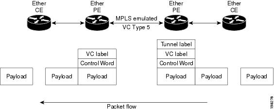
In Ethernet port mode, both ends of a pseudowire are connected to Ethernet ports. In this mode, the port is tunneled over the pseudowire or, using local switching (also known as an attachment circuit-to-attachment circuit cross-connect) switches packets or frames from one attachment circuit (AC) to another AC attached to the same PE node.

This figure shows a sample ethernet port mode packet flow:

Figure 1. Ethernet Port Mode Packet Flow

Ethernet Port Mode Packet Flow

VLAN Mode

In VLAN mode, each VLAN on a customer-end to provider-end link can be configured as a separate L2VPN connection using virtual connection (VC) type 4 or VC type 5. VC type 5 is the default mode.

As illustrated in the following figure, the Ethernet PE associates an internal VLAN-tag to the Ethernet port for switching the traffic internally from the ingress port to the pseudowire; however, before moving traffic into the pseudowire, it removes the internal VLAN tag.

Figure 2. VLAN Mode Packet Flow

VLAN Mode Packet Flow

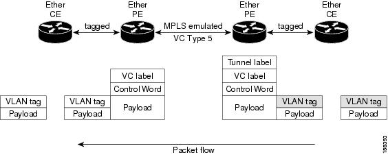
At the egress VLAN PE, the PE associates a VLAN tag to the frames coming off of the pseudowire and after switching the traffic internally, it sends out the traffic on an Ethernet trunk port.


Note

Because the port is in trunk mode, the VLAN PE doesn't remove the VLAN tag and forwards the frames through the port with the added tag.


Inter-AS Mode

Inter-AS is a peer-to-peer type model that allows extension of VPNs through multiple provider or multi-domain networks. This lets service providers peer up with one another to offer end-to-end VPN connectivity over extended geographical locations.

EoMPLS support can assume a single AS topology where the pseudowire connecting the PE routers at the two ends of the point-to-point EoMPLS cross-connects resides in the same autonomous system; or multiple AS topologies in which PE routers can reside on two different ASs using iBGP and eBGP peering.

The following figure illustrates MPLS over Inter-AS with a basic double AS topology with iBGP/LDP in each AS.

Figure 3. EoMPLS over Inter-AS: Basic Double AS Topology

QinQ Mode

QinQ is an extension of 802.1Q for specifying multiple 802.1Q tags (IEEE 802.1QinQ VLAN Tag stacking). Layer 3 VPN service termination and L2VPN service transport are enabled over QinQ sub-interfaces.

Cisco NCS 500x Series Router implement the Layer 2 tunneling or Layer 3 forwarding depending on the sub-interface configuration at provider edge routers. This function only supports up to two QinQ tags on the router:

  • Layer 2 QinQ VLANs in L2VPN attachment circuit: QinQ L2VPN attachment circuits are configured under the Layer 2 transport sub-interfaces for point-to-point EoMPLS based cross-connects using both virtual circuit type 4 and type 5 pseudowires and point-to-point local-switching-based cross-connects including full inter-working support of QinQ with 802.1q VLANs and port mode.

  • Layer 3 QinQ VLANs: Used as a Layer 3 termination point, both VLANs are removed at the ingress provider edge and added back at the remote provider edge as the frame is forwarded.

Layer 3 services over QinQ include:

  • IPv4 unicast and multicast

  • IPv6 unicast and multicast

  • MPLS

  • Connectionless Network Service (CLNS) for use by Intermediate System-to-Intermediate System (IS-IS) Protocol

In QinQ mode, each CE VLAN is carried into an SP VLAN. QinQ mode should use VC type 5, but VC type 4 is also supported. On each Ethernet PE, you must configure both the inner (CE VLAN) and outer (SP VLAN).

The following figure illustrates QinQ using VC type 4.

Figure 4. EoMPLS over QinQ Mode


Note

EoMPLS does not support pseudowire stitching or multi segments.


QinAny Mode

In the QinAny mode, the service provider VLAN tag is configured on both the ingress and the egress nodes of the provider edge VLAN. QinAny mode is similar to QinQ mode using a Type 5 VC, except that the customer edge VLAN tag is carried in the packet over the pseudowire, as the customer edge VLAN tag is unknown.

Configure Local Switching Between Attachment Circuits

Local switching involves the exchange of L2 data from one attachment circuit (AC) to the other, and between two interfaces of the same type on the same router. The two ports configured in a local switching connection form an attachment circuit (AC). A local switching connection works like a bridge domain that has only two bridge ports, where traffic enters from one port of the local connection and leaves through the other.

These are some of the characteristics of Layer 2 local switching:

  • Layer 2 local switching uses Layer 2 MAC addresses instead of the Layer 3 IP addresses.

  • Because there is no bridging involved in a local connection, there is neither MAC learning nor flooding.

  • Unlike in a bridge domain, the ACs in a local connection are not in the UP state if the interface state is DOWN.

  • Local switching ACs utilize a full variety of Layer 2 interfaces, including Layer 2 trunk (main) interfaces, bundle interfaces, and EFPs.

  • Same-port local switching allows you to switch Layer 2 data between two circuits on the same interface.

Restrictions

  • All sub-interfaces under the given physical port support only two Tag Protocol Identifiers (TPIDs), such as:
    • 0x88a8, 0x8100

    • 0x9100, 0x8100

    • 0x9200, 0x8100

  • VLAN and TPID-based ingress packet filtering is not supported.

  • Egress TPID rewrite is not supported.

Topology

An Attachment Circuit (AC) binds a Customer Edge (CE) router to a Provider Edge (PE) router. The PE router uses a pseudowire over the MPLS network to exchange routes with a remote PE router. To establish a point-to-point connection in a Layer 2 VPN from one Customer Edge (CE) router to another (remote router), a mechanism is required to bind the attachment circuit to the pseudowire. A Cross-Connect Circuit (CCC) is used to bind attachment circuits to pseudowires to emulate a point-to-point connection in a Layer 2 VPN.

The following topology is used for configuration.

Figure 5. Local Switching Between Attachment Circuits

Configuration

To configure an AC-AC local switching, complete the following configuration:

  • Enable Layer 2 transport on main interfaces.

  • Create sub-interfaces with Layer 2 transport enabled, and specify the respective encapsulation for each.

  • Enable local switching between the main interfaces, and between the sub-interfaces.

    • Create a cross-connect group.

    • Create a point-to-point cross connect circuit (CCC).

    • Assign interface(s) to the point-to-point cross connect group.


/* Enter the interface configuration mode and configure 
  L2 transport on the TenGigE interfaces */
Router# configure
Router(config)# interface TenGigE 0/0/0/1 l2transport
Router(config-if-l2)# no shutdown
Router(config-if)# exit
Router(config)# interface TenGigE 0/0/0/9 l2transport
Router(config-if-l2)# no shutdown
Router(config-if-l2)# commit

/* Configure L2 transport and encapsulation on the VLAN sub-interfaces */
Router# configure
Router(config)# interface TenGigE 0/0/0/0.1 l2transport
Router(config-subif)# encapsulation dot1q 5 
Router(config-subif)# exit
Router(config)# interface TenGigE 0/0/0/8.1 l2transport
Router(config-subif)# encapsulation dot1q 5 
Router(config-subif)# commit


/* Configure ethernet link bundles */
Router# configure
Router(config)# interface Bundle-Ether 3 
Router(config-if)# ipv4 address 10.1.3.3 255.0.0.0
Router(config-if)# bundle maximum-active links 32 hot-standby
Router(config-if)# bundle minimum-active links 1
Router(config-if)# bundle minimum-active bandwidth 30000000
Router(config-if)# exit

Router(config)# interface Bundle-Ether 2 
Router(config-if)# ipv4 address 10.1.2.2 255.0.0.0
Router(config-if)# bundle maximum-active links 32 hot-standby
Router(config-if)# bundle minimum-active links 1
Router(config-if)# bundle minimum-active bandwidth 30000000
Router(config-if)# exit

/* Add physical interfaces to the ethernet link bundles */
Router(config)# interface TenGigE 0/0/0/1
Router(config-if)# bundle id 3 mode on
Router(config-if)# no shutdown
Router(config)# exit
Router(config)# interface TenGigE 0/0/0/2
Router(config-if)# bundle id 3 mode on
Router(config-if)# no shutdown
Router(config)# exit
Router(config)# interface TenGigE 0/0/0/9 
Router(config-if)# bundle id 2 mode on
Router(config-if)# no shutdown
Router(config-if)# exit
Router(config)# interface TenGigE 0/0/0/8 
Router(config-if)# bundle id 2 mode on
Router(config-if)# no shutdown
Router(config-if)# exit

/* Configure Layer 2 transport on the ethernet link bundles */
Router(config)# interface Bundle-Ether 3 l2transport
Router(config-if-l2)# no shutdown
Router(config-if)# exit
Router(config)# interface Bundle-Ether 2 l2transport
Router(config-if-l2)# no shutdown
Router(config-if-l2)# commit

/* Configure local switching on the TenGigE Interfaces */
Router(config)# l2vpn
Router(config-l2vpn)# xconnect group XCON1
Router(config-l2vpn-xc)# p2p XCON1_P2P3
Router(config-l2vpn-xc-p2p)# interface TenGigE0/0/0/1
Router(config-l2vpn-xc-p2p)# interface TenGigE0/0/0/9
Router(config-l2vpn-xc-p2p)# commit
Router(config-l2vpn-xc-p2p)# exit

/* Configure local switching on the VLAN sub-interfaces */
Router(config-l2vpn-xc)# p2p XCON1_P2P1
Router(config-l2vpn-xc-p2p)# interface TenGigE0/0/0/0.1
Router(config-l2vpn-xc-p2p)# interface TenGigE0/0/0/8.1
Router(config-l2vpn-xc-p2p)# commit
Router(config-l2vpn-xc-p2p)# exit

/* Configure local switching on ethernet link bundles */
Router(config-l2vpn-xc)# p2p XCON1_P2P4
Router(config-l2vpn-xc-p2p)# interface Bundle-Ether 3
Router(config-l2vpn-xc-p2p)# interface Bundle-Ether 2
Router(config-l2vpn-xc-p2p)# commit


Running Configuration


configure
 interface tenGigE 0/0/0/1 l2transport
 !
 interface tenGigE 0/0/0/9 l2transport
 !
!

interface tenGigE 0/0/0/0.1 l2transport
 encapsulation dot1q 5 
 rewrite ingress tag push dot1q 20 symmetric
 !
interface tenGigE 0/0/0/8.1 l2transport
  encapsulation dot1q 5 
 !
interface Bundle-Ether 3 l2transport
 !
interface Bundle-Ether 2 l2transport
!

l2vpn
 xconnect group XCON1
   p2p XCON1_P2P3
    interface TenGigE0/0/0/1
    interface TenGigE0/0/0/9
    !
   !
 !
l2vpn
 xconnect group XCON1
   p2p XCON1_P2P1
    interface TenGigE0/0/0/0.1
    interface TenGigE0/0/0/8.1
    !
   !
 !
l2vpn
 xconnect group XCON1
   p2p XCON1_P2P4
    interface Bundle-Ether 3
    interface Bundle-Ether 2
    !
   !
 !

Verification

  • Verify if the configured cross-connect is UP

    
    router# show l2vpn xconnect brief
    
    Locally Switching
    
      Like-to-Like                        UP       DOWN        UNR
    
        EFP                                1          0          0
    
        Total                              1          0          0
    
    
      Total                                1          0          0
    
    Total: 1 UP, 0 DOWN, 0 UNRESOLVED


    router# show l2vpn xconnect
    
    Legend: ST = State, UP = Up, DN = Down, AD = Admin Down, UR = Unresolved,
            SB = Standby, SR = Standby Ready, (PP) = Partially Programmed
    
    XConnect                   Segment 1                       Segment 2
    Group      Name       ST   Description            ST       Description       ST
    ------------------------   -------------------------------------------------------------
    XCON1      XCON_P2P1 UP   Te0/0/0/1      UP  Te0/0/0/9      UP
    XCON1      XCON_P2P3 UP   Te0/0/0/0.1    UP  Te0/0/0/8.1    UP
    ----------------------------------------------------------------------------------------


Associated Commands

Configure Static Point-to-Point Connections Using Cross-Connect Circuits

This section describes how you can configure static point-to-point cross connects in a Layer 2 VPN.

Requirements and Limitations

Before you can configure a cross-connect circuit in a Layer 2 VPN, ensure that the following requirements are met:

  • The CE and PE routers are configured to operate in the MPLS network.

  • The name of a cross-connect circuit is configured to identify a pair of PE routers and must be unique within the cross-connect group.

  • A segment (an attachment circuit or pseudowire) is unique and can belong only to a single cross-connect circuit.

  • A static virtual circuit local label is globally unique and can be used in only one pseudowire.

  • A maximum of 16,000 cross-connects can be configured per PE router.


Note

Static pseudowire connections do not use LDP for signaling.


Topology

The following topology is used to configure static cross-connect circuits in a Layer 2 VPN.

Figure 6. Static Cross-Connect Circuits in a Layer 2 VPN

Configuration

/* Configure PE1 */
Router# configure 
Router(config)# l2vpn 
Router(config-l2vpn)# xconnect group XCON1
Router(config-l2vpn-xc)# p2p xc1
Router(config-l2vpn-xc-p2p)# interface gigabitethernet0/1/0/0.1
Router(config-l2vpn-xc-p2p)# neighbor 10.165.100.151 pw-id 100
Router(config-l2vpn-xc-p2p-pw)# mpls static label local 50 remote 40
Router(config-l2vpn-xc-p2p-pw)# commit
/*Configure PE2 */
Router# configure 
Router(config)# l2vpn
Router(config-l2vpn)# xconnect group XCON1
Router(config-l2vpn-xc)# p2p xc1
Router(config-l2vpn-xc-p2p)# interface gigabitethernet0/2/0/0.4
Router(config-l2vpn-xc-p2p)# neighbor 10.165.200.254 pw-id 100
Router(config-l2vpn-xc-p2p-pw)# mpls static label local 40 remote 50
Router(config-l2vpn-xc-p2p-pw)# commit

Running Configuration

/* On PE1 */
!
l2vpn
 xconnect group XCON1
  p2p xc1
   interface GigabitEthernet0/1/0/0.1
   neighbor ipv4 10.165.100.151 pw-id 100
    mpls static label local 50 remote 40
!

/* On PE2 */
!
l2vpn
 xconnect group XCON2
  p2p xc1
   interface GigabitEthernet0/2/0/0.4
   neighbor ipv4 10.165.200.254 pw-id 100
    mpls static label local 40 remote 50
  !

Verification

/* Verify the static cross connect on PE1 */
Router# show l2vpn xconnect 
Tue Apr 12 20:18:02.971 IST
Legend: ST = State, UP = Up, DN = Down, AD = Admin Down, UR = Unresolved,
        SB = Standby, SR = Standby Ready, (PP) = Partially Programmed

XConnect                   Segment 1                       Segment 2                
Group      Name       ST   Description            ST       Description            ST    
------------------------   -----------------------------   -----------------------------
XCON1      xc1        UP   Gi0/1/0/0.1            UP       10.165.100.151  100    UP    
----------------------------------------------------------------------------------------

/* Verify the static cross connect on PE2 */

Router# show l2vpn xconnect 
Tue Apr 12 20:18:02.971 IST
Legend: ST = State, UP = Up, DN = Down, AD = Admin Down, UR = Unresolved,
        SB = Standby, SR = Standby Ready, (PP) = Partially Programmed

XConnect                   Segment 1                       Segment 2                
Group      Name       ST   Description            ST       Description            ST    
------------------------   -----------------------------   -----------------------------
XCON2      xc1        UP   Gi0/2/0/0.4            UP       10.165.200.254  100    UP    
----------------------------------------------------------------------------------------

Configure Dynamic Point-to-point Cross-Connects

Perform this task to configure dynamic point-to-point cross-connects.


Note

For dynamic cross-connects, LDP must be up and running.


Configuration


Router# configure 
Router(config)# l2vpn 
Router(config-l2vpn)# xconnect group vlan_grp_1
Router(config-l2vpn-xc)# p2p vlan1
Router(config-l2vpn-xc-p2p)# interface TenGigE 0/0/0/0.1
Router(config-l2vpn-xc-p2p)# neighbor 2.2.1.1 pw-id 1
Router(config-l2vpn-xc-p2p-pw)# commit

Running Configuration


configure
  l2vpn
   xconnect group vlan_grp_1
    p2p vlan1
    interface TenGigE 0/0/0/0.1
    neighbor 2.2.1.1 pw-id 1
!

Configure Inter-AS

The Inter-AS configuration procedure is identical to the L2VPN cross-connect configuration tasks (see Configure Static Point-to-Point Connections Using Cross-Connect Circuits section and Configure Dynamic Point-to-point Cross-Connects section), except that the remote PE IP address used by the cross-connect configuration is now reachable through iBGP peering.


Note

You must be knowledgeable about IBGP, EBGP, and ASBR terminology and configurations to complete this configuration.


Flexible Cross-Connect Service

The flexible cross-connect service feature enables aggregation of attachment circuits (ACs) across multiple endpoints in a single Ethernet VPN Virtual Private Wire Service (EVPN-VPWS) service instance, on the same Provider Edge (PE). ACs are represented either by a single VLAN tag or double VLAN tags. The associated AC with the same VLAN tag(s) on the remote PE is cross-connected. The VLAN tags define the matching criteria to be used in order to map the frames on an interface to the appropriate service instance. As a result, the VLAN rewrite value must be unique within the flexible cross-connect (FXC) instance to create the lookup table. The VLAN tags can be made unique using the rewrite configuration. The lookup table helps determine the path to be taken to forward the traffic to the corresponding destination AC. This feature reduces the number of tunnels by muxing VLANs across many interfaces. It also reduces the number of MPLS labels used by a router. This feature supports both single-homing and multi-homing.

Flexible Cross-Connect Service - Single-Homed

Consider the following topology in which the traffic flows from CE1 and CE2 to PE1 through ACs. ACs are aggregated across multiple endpoints on the same PE. The VLAN (rewrite) creates the lookup table based on the rewrite configured at AC interfaces on PE1. PE1 uses BGP to exchange routes with PE2 and creates a tunnel over EVPN MPLS network. The VLANs (rewrite) on PE2 must match the rewrite configured on PE1. Based on the rewrite tag, the PE2 forwards the traffic to the corresponding ACs. For example, if the ACs for CE1 and CE3 are configured with the same rewrite tag, the end-to-end traffic is sent from CE1 to CE3.

Figure 7. Flexible Cross-Connect Service

Flexible Cross-Connect Service

Flexible Cross-Connect Service - Multi-Homed

The Flexible Cross-Connect Service multihoming capability enables you to connect a customer edge (CE) device to two or more provider edge (PE) devices to provide load balancing and redundant connectivity. Flow-based load balancing is used to send the traffic between PEs and CEs. Flow-based load balancing is used to connect source and remote PEs as well. The customer edge device is connected to PE through Ethernet bundle interface.

When a CE device is multi-homed to two or more PEs and when all PEs can forward traffic to and from the multi-homed device for the VLAN, then such multihoming is referred to as all-active multihoming.

Figure 8. Flexible Cross-Connect Service Multi-Homed

Consider the topology in which CE1 and CE2 are multi-homed to PE1 and PE2; CE3 and CE4 are multi-homed to PE3 and PE4. PE1 and PE2 advertise Ethernet A-D Ethernet Segment (ES-EAD) route to remote PEs that is PE3 and PE4. Similarly, PE3 and PE4 advertise ES-EAD route to remote PEs that is PE1 and PE2. The ES-EAD route is advertised per main interface.

Consider a traffic flow from CE1 to CE3. Traffic is sent to either PE1 or PE2. The selection of path is dependent on the CE implementation for forwarding over a LAG. Traffic is encapsulated at each PE and forwarded to the remote PEs (PE 3 and PE4) through the MPLS tunnel. Selection of the destination PE is established by flow-based load balancing. PE3 and PE4 send the traffic to CE3. The selection of path from PE3 or PE4 to CE3 is established by flow-based load balancing.

Flexible Cross-Connect Service Supported Modes

The Flexible Cross-Connect Service feature supports the following modes:
  • VLAN Unaware

  • VLAN Aware

  • Local Switching

VLAN Unaware

In this mode of operation, a group of normalized ACs on a single ES that are destined to a single endpoint or interface are multiplexed into a single EVPN VPWS tunnel represented by a single VPWS service ID. The VLAN-Unaware FXC reduces the number of BGP states. VLAN failure is not signaled over BGP. One EVI/EAD route is advertised per VLAN-Unaware FXC rather than per AC. In multihoming scenario, there will be ES-EAD route as well. EVI can be shared with other VLAN-Unaware FXC or EVPN VPWS. If AC goes down on PE1, the remote PE is not be informed of the failure, and PE3 or PE4 continues to send the traffic to PE1 and PE2 resulting in packet drop.

Multihoming is supported on VLAN Unaware FXC only if all ACs belong to the same main interface.

If you have multiple ESIs, regardless of whether it is a zero-ESI or non-zero ESI, only ESI 0 is signalled. Only single-home mode is supported in this scenario.

Configure Single-Homed Flexible Cross-Connect Service using VLAN Unaware

This section describes how you can configure single-homed flexible cross-connect service using VLAN unaware

/* Configure PE1 */
Router# configure 
Router(config)# interface GigabitEthernet 0/2/0/3.1 l2transport 
Router(config-l2vpn-subif)# encapsulation dot1q 1
Router(config-l2vpn-subif)# rewrite ingress tag translate 1-to-2 dot1q 500 second-dot1q 100 symetric
Router(config-l2vpn-subif)# commit
Router(config-l2vpn-subif)# exit
Router(config)# interface GigabitEthernet 0/2/0/0.1 l2transport 
Router(config-l2vpn-subif)# encapsulation dot1q 1
Router(config-l2vpn-subif)# rewrite ingress tag translate 1-to-2 dot1q 600 second-dot1q 200 symetric
Router(config-l2vpn-subif)# commit
Router(config-l2vpn-subif)# exit
Router(config)# l2vpn
Router(config-l2vpn)# flexible-xconnect-service vlan-unaware fxs1
Router(config-l2vpn-fxs-vu)# interface GigabitEthernet 0/2/0/3.1
Router(config-l2vpn-fxs-vu)# interface GigabitEthernet 0/2/0/0.1 
Router(config-l2vpn-fxs-vu)# neighbor evpn evi 1 target 1
Router(config-l2vpn-fxs-vu)# commit
/* Configure PE2 */
Router# configure 
Router(config)# interface GigabitEthernet 0/0/0/3.1 l2transport 
Router(config-l2vpn-subif)# encapsulation dot1q 1
Router(config-l2vpn-subif)# rewrite ingress tag translate 1-to-2 dot1q 500 second-dot1q 100 symetric
Router(config-l2vpn-subif)# commit
Router(config-l2vpn-subif)# exit
Router(config)# interface GigabitEthernet 0/0/0/0.1 l2transport 
Router(config-l2vpn-subif)# encapsulation dot1q 1
Router(config-l2vpn-subif)# rewrite ingress tag translate 1-to-2 dot1q 600 second-dot1q 200 symetric
Router(config-l2vpn-subif)# commit
Router(config-l2vpn-subif)# exit
Router(config)# l2vpn
Router(config-l2vpn)# flexible-xconnect-service vlan-unaware fxs1
Router(config-l2vpn-fxs-vu)# interface GigabitEthernet 0/0/0/3.1
Router(config-l2vpn-fxs-vu)# interface GigabitEthernet 0/0/0/0.1  
Router(config-l2vpn-fxs-vu)# neighbor evpn evi 1 target 1
Router(config-l2vpn-fxs-vu)# commit
Running Configuration
/* On PE1 */
!
Configure
interface GigabitEthernet 0/2/0/3.1 l2transport
  encapsulation dot1q 1
  rewrite ingress tag translate 1-to-2 dot1q 500 second-dot1q 100 symetric 
!

Configure
interface GigabitEthernet 0/2/0/0.1 l2transport
  encapsulation dot1q 1
  rewrite ingress tag translate 1-to-2 dot1q 600 second-dot1q 200 symetric
!

l2vpn 
  flexible-xconnect-service vlan-unaware fxs1
   interface GigabitEthernet 0/2/0/3.1
   interface GigabitEthernet0/2/0/0.1
   neighbor evpn evi 1 target 1
  
!

/* On PE2 */
!
Configure
interface GigabitEthernet 0/0/0/3.1 l2transport
  encapsulation dot1q 1
  rewrite ingress tag translate 1-to-2 dot1q 500 second-dot1q 100 symetric 
!

Configure
interface GigabitEthernet 0/0/0/0.1 l2transport
  encapsulation dot1q 1
  rewrite ingress tag translate 1-to-2 dot1q 600 second-dot1q 200 symetric
!

l2vpn 
  flexible-xconnect-service vlan-unaware fxs1
   interface GigabitEthernet 0/0/0/3.1
   interface GigabitEthernet0/0/0/0.1
   neighbor evpn evi 1 target 1
  
!

Configure Multi-Homed Flexible Cross-Connect Service using VLAN Unaware

This section describes how you can configure multi-homed flexible cross-connect service using VLAN unaware.

/* Configure PE1 */
Router# configure 
Router(config)# l2vpn 
Router(config-l2vpn)# flexible-xconnect-service vlan-unaware fxc1_16
Router(config-l2vpn-fxs)# interface Bundle-Ether10.11
Router(config-l2vpn-fxs)# interface Bundle-Ether10.12
Router(config-l2vpn-fxs)# neighbor evpn evi 1 target 16
Router(config-l2vpn-fxs)# commit
Router(config-l2vpn-fxs)# exit
Router(config-l2vpn)# exit
Router(config)# interface Bundle-Ether10.11 l2transport 
Router(config-l2vpn-subif)# encapsulation dot1q 1
Router(config-l2vpn-subif)# rewrite ingress tag translate 1-to-1 dot1q 11 symmetric
Router(config-l2vpn-subif)# commit
Router(config-l2vpn-subif)# exit
Router(config)# interface Bundle-Ether10.12 l2transport 
Router(config-l2vpn-subif)# encapsulation dot1q 2
Router(config-l2vpn-subif)# rewrite ingress tag translate 1-to-1 dot1q 12 symmetric
Router(config-subif)# commit
Router(config-subif)# exit
Router(config)# evpn
Router (config-evpn)# interface Bundle-Ether10
Router (config-evpn-ac)# ethernet-segment
Router (config-evpn-ac-es)# identifier type  0 00.01.00.ac.ce.55.00.0a.00
Router (config-evpn-ac-es)# commit
/* Configure PE2 */
Router# configure 
Router(config)# l2vpn 
Router(config-l2vpn)# flexible-xconnect-service vlan-unaware fxc1_16
Router(config-l2vpn-fxs-vu)# interface Bundle-Ether10.11
Router(config-l2vpn-fxs)# interface Bundle-Ether10.12
Router(config-l2vpn-fxs)# neighbor evpn evi 1 target 16
Router(config-l2vpn-fxs)# commit
Router(config-l2vpn-fxs)# exit
Router(config-l2vpn)# exit
Router(config)# interface Bundle-Ether10.11 l2transport 
Router(config-l2vpn-subif)# encapsulation dot1q 1
Router(config-l2vpn-subif)# rewrite ingress tag translate 1-to-1 dot1q 11 symmetric
Router(config-l2vpn-subif)# commit
Router(config-l2vpn-subif)# exit
Router(config)# interface Bundle-Ether10.12 l2transport 
Router(config-l2vpn-subif)# encapsulation dot1q 2
Router(config-l2vpn-subif)# rewrite ingress tag translate 1-to-1 dot1q 12 symmetric
Router(config-subif)# commit
Router(config-subif)# exit
Router(config)# evpn
Router (config-evpn)# interface Bundle-Ether10
Router (config-evpn-ac)# ethernet-segment
Router (config-evpn-ac-es)# identifier type  0 00.01.00.ac.ce.55.00.0a.00
Router (config-evpn-ac-es)# commit
/* Configure PE3 */
Router# configure 
Router(config)# l2vpn 
Router(config-l2vpn)# flexible-xconnect-service vlan-unaware fxc1_16
Router(config-l2vpn-fxs-vu)# interface Bundle-Ether20.11
Router(config-l2vpn-fxs)# interface Bundle-Ether20.12
Router(config-l2vpn-fxs)# neighbor evpn evi 1 target 16
Router(config-l2vpn-fxs)# commit
Router(config-l2vpn-fxs)# exit
Router(config-l2vpn)# exit
Router(config)# interface Bundle-Ether20.11 l2transport 
Router(config-l2vpn-subif)# encapsulation dot1q 1
Router(config-l2vpn-subif)# rewrite ingress tag translate 1-to-1 dot1q 11 symmetric
Router(config-l2vpn-subif)# commit
Router(config-subif)# exit
Router(config)# interface Bundle-Ether20.12 l2transport 
Router(config-l2vpn-subif)# encapsulation dot1q 2
Router(config-l2vpn-subif)# rewrite ingress tag translate 1-to-1 dot1q 12 symmetric
Router(config-l2vpn-subif)# commit
Router(config-subif)# exit
Router(config)# evpn
Router (config-evpn)# interface Bundle-Ether20
Router (config-evpn-ac)# ethernet-segment
Router (config-evpn-ac-es)# identifier type  0 00.01.00.ac.ce.55.00.14.00
Router (config-evpn-ac-es)# commit
/* Configure PE4 */
Router# configure 
Router(config)# l2vpn 
Router(config-l2vpn)# flexible-xconnect-service vlan-unaware fxc1_16
Router(config-l2vpn-fxs-vu)# interface Bundle-Ether20.11
Router(config-l2vpn-fxs)# interface Bundle-Ether20.12
Router(config-l2vpn-fxs)# neighbor evpn evi 1 target 16
Router(config-l2vpn-fxs)# commit
Router(config-l2vpn-fxs)# exit
Router(config-l2vpn)# exit
Router(config)# interface Bundle-Ether20.11 l2transport 
Router(config-l2vpn-subif)# encapsulation dot1q 1
Router(config-l2vpn-subif)# rewrite ingress tag translate 1-to-1 dot1q 11 symmetric
Router(config-l2vpn-subif)# commit
Router(config-subif)# exit
Router(config)# interface Bundle-Ether20.12 l2transport 
Router(config-l2vpn-subif)# encapsulation dot1q 2
Router(config-l2vpn-subif)# rewrite ingress tag translate 1-to-1 dot1q 12 symmetric
Router(config-l2vpn-subif)# commit
Router(config-subif)# exit
Router(config)# evpn
Router (config-evpn)# interface Bundle-Ether20
Router (config-evpn-ac)# ethernet-segment
Router (config-evpn-ac-es)# identifier type  0 00.01.00.ac.ce.55.00.14.00
Router (config-evpn-ac-es)# commit

Running Configuration
/* On PE1 */

configure
l2vpn
 flexible-xconnect-service vlan-unaware fxc1_16
  interface Bundle-Ether10.11
	 interface Bundle-Ether10.12
		neighbor evpn evi 1 target 16
  
!

configure
interface Bundle-Ether10.11 l2transport
  encapsulation dot1q 1
  rewrite ingress tag translate 1-to-1 dot1q 11 symmetric 

!


configure
interface Bundle-Ether10.12 l2transport
  encapsulation dot1q 2
  rewrite ingress tag translate 1-to-1 dot1q 12 symmetric 

!

evpn 
  interface Bundle-Ether10
   ethernet-segment identifier type 0 00.01.00.ac.ce.55.00.0a.00
  
!

/* On PE2 */

configure
l2vpn
 flexible-xconnect-service vlan-unaware fxc1_16
  interface Bundle-Ether10.11
	 interface Bundle-Ether10.12
		neighbor evpn evi 1 target 16
  
!

configure
interface Bundle-Ether10.11 l2transport
  encapsulation dot1q 1
  rewrite ingress tag translate 1-to-1 dot1q 11 symmetric 

!


configure
interface Bundle-Ether10.12 l2transport
  encapsulation dot1q 2
  rewrite ingress tag translate 1-to-1 dot1q 12 symmetric 

!

evpn 
  interface Bundle-Ether10
   ethernet-segment identifier type 0 00.01.00.ac.ce.55.00.0a.00
  
!

/* On PE3 */

configure
l2vpn
 flexible-xconnect-service vlan-unaware fxc1_16
  interface Bundle-Ether20.11
  interface Bundle-Ether20.12
		neighbor evpn evi 1 target 16
  
!

configure
interface Bundle-Ether20.11 l2transport
  encapsulation dot1q 1
  rewrite ingress tag translate 1-to-1 dot1q 11 symmetric 

!

configure
interface Bundle-Ether20.12 l2transport
  encapsulation dot1q 2
  rewrite ingress tag translate 1-to-1 dot1q 12 symmetric 

!

evpn 
  interface Bundle-Ether20
   ethernet-segment identifier type 0 00.01.00.ac.ce.55.00.14.00
  
!

/* On PE4 */

configure
l2vpn
 flexible-xconnect-service vlan-unaware fxc1_16
  interface Bundle-Ether20.11
  interface Bundle-Ether20.12
		neighbor evpn evi 1 target 16
  
!

configure
interface Bundle-Ether20.11 l2transport
  encapsulation dot1q 1
  rewrite ingress tag translate 1-to-1 dot1q 11 symmetric 

!

configure
interface Bundle-Ether20.12 l2transport
  encapsulation dot1q 2
  rewrite ingress tag translate 1-to-1 dot1q 12 symmetric 

!

evpn 
  interface Bundle-Ether20
   ethernet-segment identifier type 0 00.01.00.ac.ce.55.00.14.00
  
!

VLAN Aware

In this mode of operation, normalized ACs across different Ethernet segments and interfaces are multiplexed into a single EVPN VPWS service tunnel. This single tunnel is represented by many VPWS service IDs (one per normalized VLAN ID (VID)) and these normalized VIDs are signaled using EVPN BGP. The VLAN-Aware FXC reduces the number of PWs; but it does not reduce the BGP states. VLAN failure is signaled over BGP. The VLAN-Aware FXC advertises one EAD route per AC rather than per FXC. For VLAN-Aware FXC, the EVI must be unique to the FXC itself. It cannot be shared with any other service such as FXC, EVPN, EVPN-VPWS, PBB-EVPN. If a single AC goes down on PE1, it withdraws only the EAD routes associated with that AC. The ES-EAD route will also be withdrawn on failure of the main interface. The equal-cost multipath (ECMP) on PE3 or PE4 stops sending traffic for this AC to PE1, and only sends it to PE2.

For the same VLAN-Aware FXC, you can either configure all non-zero ESIs or all zero-ESIs. You cannot configure both zero-ESI and non-zero ESI for the same VLAN-Aware FXC. This applies only to single-home mode.

Configure Single-Homed Flexible Cross-Connect using VLAN Aware

This section describes how you can configure single-homed flexible cross-connect service using VLAN aware.

/* Configure PE1 */
Router# configure 
Router(config)#  interface GigabitEthernet 0/2/0/7.1 l2transport 
Router(config-l2vpn-subif)# encapsulation dot1q 1
Router(config-l2vpn-subif)# rewrite ingress tag translate 1-to-2 dot1q 500 second-dot1q 100 symetric
Router(config-l2vpn-subif)# commit
Router(config-l2vpn-subif)# exit
Router(config)#  interface GigabitEthernet 0/2/0/7.2 l2transport 
Router(config-l2vpn-subif)# encapsulation dot1q 2
Router(config-l2vpn-subif)# rewrite ingress tag translate 1-to-2 dot1q 600 second-dot1q 200 symetric
Router(config-l2vpn-subif)# commit
Router(config-l2vpn-subif)# exit
Router(config)# l2vpn
Router(config-l2vpn)# flexible-xconnect-service vlan-aware evi 4
Router(config-l2vpn-fxs-va)# interface GigabitEthernet 0/2/0/7.1
Router(config-l2vpn-fxs-va)# interface GigabitEthernet 0/2/0/7.2 
Router(config-l2vpn-fxs-va)# commit
/* Configure PE2 */
Router# configure 
Router(config)#  interface GigabitEthernet 0/0/0/7.1 l2transport 
Router(config-l2vpn-subif)# encapsulation dot1q 1
Router(config-l2vpn-subif)# rewrite ingress tag translate 1-to-2 dot1q 500 second-dot1q 100 symetric
Router(config-l2vpn-subif)# commit
Router(config-l2vpn-subif)# exit
Router(config)#  interface GigabitEthernet 0/0/0/7.2 l2transport 
Router(config-l2vpn-subif)# encapsulation dot1q 2
Router(config-l2vpn-subif)# rewrite ingress tag translate 1-to-2 dot1q 600 second-dot1q 200 symetric
Router(config-l2vpn-subif)# commit
Router(config-l2vpn-subif)# exit
Router(config)# l2vpn
Router(config-l2vpn)# flexible-xconnect-service vlan-aware evi 4
Router(config-l2vpn-fxs-va)# interface GigabitEthernet 0/0/0/7.1
Router(config-l2vpn-fxs-va)# interface GigabitEthernet 0/0/0/7.2  
Router(config-l2vpn-fxs-va )# commit
Running Configuration
/* On PE1 */
!
Configure
interface GigabitEthernet 0/2/0/7.1 l2transport
  encapsulation dot1q 1
  rewrite ingress tag translate 1-to-2 dot1q 500 second-dot1q 100 symetric 
!

Configure
interface GigabitEthernet 0/2/0/7.2 l2transport
  encapsulation dot1q 2
  rewrite ingress tag translate 1-to-2 dot1q 600 second-dot1q 200 symetric
!

l2vpn 
  flexible-xconnect-service vlan-aware evi 4
   interface GigabitEthernet 0/2/0/7.1
   interface GigabitEthernet 0/2/0/7.2

  
!

/* On PE2 */
!
Configure
interface GigabitEthernet 0/0/0/7.1 l2transport
  encapsulation dot1q 1
  rewrite ingress tag translate 1-to-2 dot1q 500 second-dot1q 100 symetric 
!

Configure
interface GigabitEthernet 0/0/0/7.2 l2transport
  encapsulation dot1q 2
  rewrite ingress tag translate 1-to-2 dot1q 600 second-dot1q 200 symetric
!

l2vpn 
  flexible-xconnect-service vlan-aware evi 4
   interface GigabitEthernet 0/0/0/7.1
   interface GigabitEthernet 0/0/0/7.2
  
!

Configure Multi-Homed Flexible Cross-Connect Service using VLAN Aware

This section describes how you can configure multi-homed flexible cross-connect service using VLAN aware.

/* Configure PE1 */
Router# configure 
Router(config)# l2vpn 
Router(config-l2vpn)# flexible-xconnect-service vlan-aware evi 6
Router(config-l2vpn-fxs-va)# interface Bundle-Ether2.1
Router(config-l2vpn-fxs-va)# interface Bundle-Ether3.1
Router(config-l2vpn-fxs-va)# commit
Router(config-l2vpn-fxs-va)# exit
Router(config-l2vpn)# exit
Router(config)# interface Bundle-Ether2.1 l2transport 
Router(config-l2vpn-subif)# encapsulation dot1q 1
Router(config-l2vpn-subif)# rewrite ingress tag translate 1-to-1 dot1q 11 symmetric
Router(config-l2vpn-subif)# commit
Router(config-l2vpn-subif)# exit
Router(config)# interface Bundle-Ether3.1 l2transport 
Router(config-l2vpn-subif)# encapsulation dot1q 2
Router(config-l2vpn-subif)# rewrite ingress tag translate 1-to-1 dot1q 12 symmetric
Router(config-l2vpn-subif)# commit
Router(config-l2vpn-subif)# exit
Router(config)# evpn
Router(config-evpn)# interface Bundle-Ether2
Router(config-evpn-ac)# ethernet-segment
Router(config-evpn-ac-es)# identifier type 0 22.33.44.55.66.77.88.99.aa
Router(config-evpn-ac-es)# commit
Router(config-evpn-ac-es)# exit
Router(config-evpn-ac)# exit
Router(config-evpn)# interface Bundle-Ether3
Router(config-evpn-ac)# ethernet-segment
Router(config-evpn-ac-es)# identifier type 0 33.44.55.66.77.88.99.aa.bb
Router(config-evpn-ac-es)# commit
/* Configure PE2 */
Router# configure 
Router(config)# l2vpn 
Router(config-l2vpn)# flexible-xconnect-service vlan-aware evi 6
Router(config-l2vpn-fxs-va)# interface Bundle-Ether2.1
Router(config-l2vpn-fxs-va)# interface Bundle-Ether3.1
Router(config-l2vpn-fxs-va)# commit
Router(config-l2vpn-fxs-va)# exit
Router(config-l2vpn)# exit
Router(config)# interface Bundle-Ether2.1 l2transport 
Router(config-l2vpn-subif)# encapsulation dot1q 1
Router(config-l2vpn-subif)# rewrite ingress tag translate 1-to-1 dot1q 11 symmetric
Router(config-l2vpn-subif)# commit
Router(config-l2vpn-subif)# exit
Router(config)# interface Bundle-Ether3.1 l2transport 
Router(config-l2vpn-subif)# encapsulation dot1q 2
Router(config-l2vpn-subif)# rewrite ingress tag translate 1-to-1 dot1q 12 symmetric
Router(config-l2vpn-subif)# commit
Router(config-l2vpn-subif)# exit
Router(config)# evpn
Router(config-evpn)# interface Bundle-Ether2
Router(config-evpn-ac)# ethernet-segment
Router(config-evpn-ac-es)# identifier type 0 22.33.44.55.66.77.88.99.aa
Router(config-evpn-ac-es)# commit
Router(config-evpn-ac-es)# exit
Router(config-evpn-ac)# exit
Router(config-evpn)# interface Bundle-Ether3
Router(config-evpn-ac)# ethernet-segment
Router(config-evpn-ac-es)# identifier type 0 33.44.55.66.77.88.99.aa.bb
Router(config-evpn-ac-es)# commit
/* Configure PE3 */
Router# configure 
Router(config)# l2vpn 
Router(config-l2vpn)# flexible-xconnect-service vlan-aware evi 6
Router(config-l2vpn-fxs-va)# interface Bundle-Ether4.1
Router(config-l2vpn-fxs-va)# interface Bundle-Ether5.1
Router(config-l2vpn-fxs-va)# commit
Router(config-l2vpn-fxs-va)# exit
Router(config-l2vpn)# exit
Router(config)# interface Bundle-Ether4.1 l2transport 
Router(config-l2vpn-subif)# encapsulation dot1q 1
Router(config-l2vpn-subif)# rewrite ingress tag translate 1-to-1 dot1q 11 symmetric
Router(config-l2vpn-subif)# commit
Router(config-l2vpn-subif)# exit
Router(config)# interface Bundle-Ether5.1 l2transport 
Router(config-l2vpn-subif)# encapsulation dot1q 2
Router(config-l2vpn-subif)# rewrite ingress tag translate 1-to-1 dot1q 12 symmetric
Router(config-l2vpn-subif)# commit
Router(config-l2vpn-subif)# exit
Router(config)# evpn
Router(config-evpn)# interface Bundle-Ether4
Router(config-evpn-ac)# ethernet-segment
Router(config-evpn-ac-es)# identifier type 0 00.01.00.ac.ce.55.00.14.00
Router(config-evpn-ac-es)# commit
Router(config-evpn-ac-es)# exit
Router(config-evpn-ac)# exit
Router(config-evpn)# interface Bundle-Ether5
Router(config-evpn-ac)# ethernet-segment
Router(config-evpn-ac-es)# identifier type identifier type 0 00.01.00.ac.ce.55.00.15.00
Router(config-evpn-ac-es)# commit
/* Configure PE4 */
Router# configure 
Router(config)# l2vpn 
Router(config-l2vpn)# flexible-xconnect-service vlan-aware evi 6
Router(config-l2vpn-fxs-va)# interface Bundle-Ether4.1
Router(config-l2vpn-fxs-va)# interface Bundle-Ether5.1
Router(config-l2vpn-fxs-va)# commit
Router(config-l2vpn-fxs-va)# exit
Router(config-l2vpn)# exit
Router(config)# interface Bundle-Ether4.1 l2transport 
Router(config-l2vpn-subif)# encapsulation dot1q 1
Router(config-l2vpn-subif)# rewrite ingress tag translate 1-to-1 dot1q 11 symmetric
Router(config-l2vpn-subif)# commit
Router(config-l2vpn-subif)# exit
Router(config)# interface Bundle-Ether5.1 l2transport 
Router(config-l2vpn-subif)# encapsulation dot1q 2
Router(config-l2vpn-subif)# rewrite ingress tag translate 1-to-1 dot1q 12 symmetric
Router(config-l2vpn-subif)# commit
Router(config-l2vpn-subif)# exit
Router(config)# evpn
Router(config-evpn)# interface Bundle-Ether4
Router(config-evpn-ac)# ethernet-segment
Router config-evpn-ac-es)# identifier type 0 00.01.00.ac.ce.55.00.14.00
Router(config-evpn-ac-es)# commit
Router(config-evpn-ac-es)# exit
Router(config-evpn-ac)# exit
Router(config-evpn)# interface Bundle-Ether5
Router(config-evpn-ac)# ethernet-segment
Router(config-evpn-ac-es)# identifier type identifier type 0 00.01.00.ac.ce.55.00.15.00
Router(config-evpn-ac-es)# commit
Running Configuration
/* On PE1 */
!
configure
l2vpn
 flexible-xconnect-service vlan-aware evi 6
  interface Bundle-Ether2.1
  interface Bundle-Ether3.1

!

configure
interface Bundle-Ether2.1 l2transport
  encapsulation dot1q 1
  rewrite ingress tag translate 1-to-1 dot1q 11 symmetric 

!

configure
interface Bundle-Ether3.1 l2transport
  encapsulation dot1q 2
  rewrite ingress tag translate 1-to-1 dot1q 12 symmetric
!

evpn 
  interface Bundle-Ether2
   ethernet-segment identifier type 0 22.33.44.55.66.77.88.99.aa
  interface Bundle-Ether3
   ethernet-segment identifier type 0 33.44.55.66.77.88.99.aa.bb
  
!

/* On PE2 */
!
configure
l2vpn
 flexible-xconnect-service vlan-aware evi 6
  interface Bundle-Ether2.1
  interface Bundle-Ether3.1

!

configure
interface Bundle-Ether2.1 l2transport
  encapsulation dot1q 1
  rewrite ingress tag translate 1-to-1 dot1q 11 symmetric 

!

configure
interface Bundle-Ether3.1 l2transport
  encapsulation dot1q 2
  rewrite ingress tag translate 1-to-1 dot1q 12 symmetric
!

evpn 
  interface Bundle-Ether2
   ethernet-segment identifier type 0 22.33.44.55.66.77.88.99.aa
  interface Bundle-Ether3
   ethernet-segment identifier type 0 33.44.55.66.77.88.99.aa.bb
  
!

/* On PE3 */
!
configure
l2vpn
 flexible-xconnect-service vlan-aware evi 6
  interface Bundle-Ether4.1
  interface Bundle-Ether5.1

!

configure
interface Bundle-Ether4.1 l2transport
  encapsulation dot1q 1
  rewrite ingress tag translate 1-to-1 dot1q 11 symmetric 

!

configure
interface Bundle-Ether5.1 l2transport
  encapsulation dot1q 2
  rewrite ingress tag translate 1-to-1 dot1q 12 symmetric
!

evpn 
  interface Bundle-Ether4
   ethernet-segment identifier type 0 00.01.00.ac.ce.55.00.14.00
  interface Bundle-Ether5
   ethernet-segment identifier type 0 00.01.00.ac.ce.55.00.15.00
  
!

/* On PE4 */
!
configure
l2vpn
 flexible-xconnect-service vlan-aware evi 6
  interface Bundle-Ether4.1
  interface Bundle-Ether5.1

!

configure
interface Bundle-Ether4.1 l2transport
  encapsulation dot1q 1
  rewrite ingress tag translate 1-to-1 dot1q 11 symmetric 

!

configure
interface Bundle-Ether5.1 l2transport
  encapsulation dot1q 2
  rewrite ingress tag translate 1-to-1 dot1q 12 symmetric
!

evpn 
  interface Bundle-Ether4
   ethernet-segment identifier type 0 00.01.00.ac.ce.55.00.14.00
  interface Bundle-Ether5
   ethernet-segment identifier type 0 00.01.00.ac.ce.55.00.15.00
  
!

Local Switching

Traffic between the two ACs is locally switched within the PE when two ACs belonging to different Ethernet Segment have the same normalization VLANs. Local switching is supported only on FXC VLAN-aware.

Consider a topology in which CE1 and CE2 have different Ethernet Segment. However, they both have the same normalized VLANs. Hence, when a traffic is sent from CE1 to CE2, PE1 routes the traffic to CE2 using local switching.

If there is a failure and when the link from CE1 to PE1 goes down, PE1 sends the traffic to PE2 through EVPN pseudowire. Then the PE2 sends the traffic to CE2.

CE1 and CE2 must be on different non-zero ESI.

Figure 9. Local Switching


Configure Multi-Homed Flexible Cross-Connect Service using Local Switching

This section describes how you can configure multi-homed flexible cross-connect service using local switching.

/* Configure PE1 */
Router# configure 
Router(config)# l2vpn 
Router(config-l2vpn)# flexible-xconnect-service vlan-aware evi 6
Router(config-l2vpn-fxs-va)# interface Bundle-Ether2.1
Router(config-l2vpn-fxs-va)# interface Bundle-Ether3.1
Router(config-l2vpn-fxs-va)# commit
Router(config-l2vpn-fxs)# exit
Router(config-l2vpn)# exit
Router(config)# interface Bundle-Ether2.1 l2transport 
Router(config-l2vpn-subif)# encapsulation dot1q 1
Router(config-l2vpn-subif)# rewrite ingress tag translate 1-to-2 dot1q 3 second-dot1q 3 symmetric
Router(config-l2vpn-subif)# commit
Router(config-l2vpn-subif)# exit
Router(config)# interface Bundle-Ether3.1 l2transport 
Router(config-l2vpn-subif)# encapsulation dot1q 1
Router(config-l2vpn-subif)# rewrite ingress tag translate 1-to-2 dot1q 3 second-dot1q 3 symmetric
Router(config-l2vpn-subif)# commit
Router(config-l2vpn-subif)# exit
Router(config)# evpn
Router(config-evpn)# interface Bundle-Ether2
Router(config-evpn-ac)# ethernet-segment
Router(config-evpn-ac-es)# identifier type 0 22.33.44.55.66.77.88.99.aa
Router(config-evpn-ac-es)# commit
Router(config-evpn-ac-es)# exit
Router(config-evpn-ac)# exit
Router(config-evpn)# interface Bundle-Ether3
Router(config-evpn-ac)# ethernet-segment
Router(config-evpn-ac-es)# identifier type 0 33.44.55.66.77.88.99.aa.bb
Router(config-evpn-ac-es)# commit
/* Configure PE2 */
Router# configure 
Router(config)# l2vpn 
Router(config-l2vpn)# flexible-xconnect-service vlan-aware evi 6
Router(config-l2vpn-fxs-va)# interface Bundle-Ether2.1
Router(config-l2vpn-fxs-va)# interface Bundle-Ether3.1
Router(config-l2vpn-fxs-va)# commit
Router(config-l2vpn-fxs)# exit
Router(config-l2vpn)# exit
Router(config)# interface Bundle-Ether2.1 l2transport 
Router(config-l2vpn-subif)# encapsulation dot1q 1
Router(config-l2vpn-subif)# rewrite ingress tag translate 1-to-2 dot1q 3 second-dot1q 3 symmetric
Router(config-l2vpn-subif)# commit
Router(config-l2vpn-subif)# exit
Router(config)# interface Bundle-Ether3.1 l2transport 
Router(config-l2vpn-subif)# encapsulation dot1q 1
Router(config-l2vpn-subif)# rewrite ingress tag translate 1-to-2 dot1q 3 second-dot1q 3 symmetric
Router(config-l2vpn-subif)# commit
Router(config-l2vpn-subif)# exit
Router(config)# evpn
Router(config-evpn)# interface Bundle-Ether2
Router(config-evpn-ac)# ethernet-segment
Router(config-evpn-ac-es)# identifier type 0 22.33.44.55.66.77.88.99.aa
Router(config-evpn-ac-es)# commit
Router(config-evpn-ac-es)# exit
Router(config-evpn-ac)# exit
Router(config-evpn)# interface Bundle-Ether3
Router(config-evpn-ac)# ethernet-segment
Router(config-evpn-ac-es)# identifier type 0 33.44.55.66.77.88.99.aa.bb
Router(config-evpn-ac-es)# commit
Running Configuration
/* On PE1 */

configure
l2vpn
 flexible-xconnect-service vlan-aware evi 6
  interface Bundle-Ether2.1
  interface Bundle-Ether3.1

!

configure
interface Bundle-Ether2.1 l2transport
  encapsulation dot1q 1
  rewrite ingress tag translate 1-to-2 dot1q 3 second-dot1q 3 symmetric 

!

configure
interface Bundle-Ether3.1 l2transport
  encapsulation dot1q 1
  rewrite ingress tag translate 1-to-2 dot1q 3 second-dot1q 3 symmetric
!

evpn 
  interface Bundle-Ether2
   ethernet-segment identifier type 0 22.33.44.55.66.77.88.99.aa
  interface Bundle-Ether3
   ethernet-segment identifier type 0 33.44.55.66.77.88.99.aa.bb
  
!

/* On PE2 */

configure
l2vpn
 flexible-xconnect-service vlan-aware evi 6
  interface Bundle-Ether2.1
  interface Bundle-Ether3.1

!

configure
interface Bundle-Ether2.1 l2transport
  encapsulation dot1q 1
  rewrite ingress tag translate 1-to-2 dot1q 3 second-dot1q 3 symmetric 

!

configure
interface Bundle-Ether3.1 l2transport
  encapsulation dot1q 1
  rewrite ingress tag translate 1-to-2 dot1q 3 second-dot1q 3 symmetric
!

evpn 
  interface Bundle-Ether2
   ethernet-segment identifier type 0 22.33.44.55.66.77.88.99.aa
  interface Bundle-Ether3
   ethernet-segment identifier type 0 33.44.55.66.77.88.99.aa.bb
  
  
!

AC-Aware VLAN Bundle

The AC-Aware VLAN Bundle feature allows you to configure more than one subinterface on the same main port in an EVPN enabled bridge domain.

Without this feature, MAC routes identify originating interface using only ESI. When there are multiple subinterfaces with the same ESI, there is no way to distinguish one from the other. Bridge Port (BP) stamping is done with only the EVI and ESI.

With this feature a peering node hosting the advertised ESI performs BP-stamping to a proper local subinterface.

Figure 10. Topology

In this topology, when the traffic from CE1 flows to PE1, PE1 floods the message to the other PEs. As PE2 is directly connected to CE1, a loop is formed between these PEs. To avoid the loop, the traffic from local CE1 subinterface on PE1 to remote CE1 subinterface on PE2 is prevented using ESI filtering.

The AC-Aware VLAN Bundle feature is enabled by default which allows you to configure more than one subinterface on the same main port in an EVPN enabled bridge domain. This feature conforms to draft-sajassi-bess-evpn-ac-aware-bundling. Here, the Attachment Circuit ID (AC-ID) is signaled using new EVPN BGP Extended Community.

Configure Preferred Tunnel Path

Preferred tunnel path functionality lets you map pseudowires to specific traffic-engineering tunnels. Attachment circuits are cross-connected to specific MPLS traffic engineering tunnel interfaces instead of remote PE router IP addresses (reachable using IGP or LDP).

When using a preferred tunnel path, it is assumed that the traffic engineering tunnel that transports the Layer 2 traffic runs between the two PE routers (that is, its head starts at the imposition PE router and its tail terminates on the disposition PE router).

Configuration


/* Enter global configuration mode */
Router# configure
Router(config)# l2vpn

/* Configure pseudowire class name */
Router(config-l2vpn)# pw-class path1

/* Configure MPLS encapsulation for the pseudowire */
Router(config-l2vpn-pwc)# encapsulation mpls


/* Configure preferred path tunnel settings. 
If fallback disable configuration is used, and when
 the TE/ tunnel is configured, 
 if the preferred path goes down, 
 the corresponding pseudowire can also go down. */

Router(config-l2vpn-pwc-encap-mpls)# preferred-path 
                   interface tunnel-te 11 fallback disable

/* Commit your configuration */
Router(config-l2vpn-pwc)# exit
Router(config-l2vpn)# commit

Running Configuration


Router# show running-configuration
! 
l2vpn
 pw-class path1
  encapsulation mpls
   preferred-path interface tunnel-te 11 fallback disable
  !
 !
!

Multisegment Pseudowire

The Multisegment Pseudowire feature allows you to extend L2VPN pseudowires across an inter-AS boundary or across two separate MPLS networks. A multisegment pseudowire connects two or more contiguous pseudowire segments to form an end-to-end multi-hop pseudowire as a single point-to-point pseudowire. These segments act as a single pseudowire, allowing you to:

  • Manage the end-to-end service by separating administrative or provisioning domains.

  • Keep IP addresses of provider edge (PE) nodes private across interautonomous system (inter-AS) boundaries. Use IP address of autonomous system boundary routers (ASBRs) and treat them as pseudowire aggregation routers. The ASBRs join the pseudowires of the two domains.

A multisegment pseudowire can span either an inter-AS boundary or two multiprotocol label switching (MPLS) networks.

A pseudowire is a tunnel between two PE nodes. There are two types of PE nodes:

  • A Switching PE (S-PE) node

    • Terminates PSN tunnels of the preceding and succeeding pseudowire segments in a multisegment pseudowire.

    • Switches control and data planes of the preceding and succeeding pseudowire segments of the multisegment pseudowire.

  • A Terminating PE (T-PE) node

    • Located at both the first and last segments of a multisegment pseudowire.

    • Where customer-facing attachment circuits (ACs) are bound to a pseudowire forwarder.


Note

Every end of a multisegment pseudowire must terminate at a T-PE.


A multisegment pseudowire is used in two general cases when:

  • It is not possible to establish a PW control channel between the source and destination PE nodes.

    For the PW control channel to be established, the remote PE node must be accessible. Sometimes, the local PE node may not be able to access the remote node due to topology, operational, or security constraints.

    A multisegment pseudowire dynamically builds two discrete pseudowire segments and performs a pseudowire switching to establish a PW control channel between the source and destination PE nodes.

  • Pseudowire Edge To Edge Emulation (PWE3) signaling and encapsulation protocols are different.

    The PE nodes are connected to networks employing different PW signaling and encapsulation protocols. Sometimes, it is not possible to use a single segment PW.

    A multisegment pseudowire, with the appropriate interworking performed at the PW switching points, enables PW connectivity between the PE nodes in the network.

Figure 11. Multisegment Pseudowire


The topology shows MS-PW stitching between PW1 and PW2. You can configure a set of two or more contiguous PW segments that behave and function as a single point-to-point PW. You can configure static or dynamic multisegment PW (MS-PW). The maximum number of contiguous PW segments is 254. Each end of an MS-PW terminates on a T-PE. A switching PE (S-PE) terminates the PSN tunnels of the preceding and succeeding PW segments in an MS-PW. The S-PE switches the control and data planes of the preceding and succeeding PW segments of the MS-PW. An MS-PW is up when all the SS-PWs are up.

Restrictions

You must consider the following restrictions while configuring the Multisegment Pseudowire feature:

  • Connect both segments of an MS-PW to different peers.

  • Supports only LDP and does not support L2TPv3. Each PW segment in the MS-PW xconnect can be either static or dynamic.

  • The neighbor pw-id pair of each PW segment of an MS-PW is unique on the node.

  • The end-to-end pw-type has to be the same. Hence, both segments of an MS-PW must have the same transport mode.

  • You cannot configure PW redundancy on an MS-PW xconnect at the S-PE. You can configure PW redundancy at the T-PEs.

  • Both segments of an MS-PW xconnect can not have the same preferred path.

  • Supports MS-PW over LDP, MPLS-TE, SR, and SR-TE as transport protocols.

  • Does not support MS-PW over BGP-LU and LDPoTE.

  • When you enable MSPW on an S-PE, configure the ip-ttl-propagation disable command for the MSPW ping and traceroute to work. Alternatively, use segment-count 255 option for MSPW ping to work from T-PE1. MSPW does not support the partial ping.

Multisegment Pseudowire Redundancy

Pseudowire redundancy enables you to create backup MS-PWs between the T-PEs. Pseudowire redundancy allows you to configure your network to detect a failure in the network. And reroute the Layer 2 service to another endpoint that can continue to provide service.

Figure 12. Multisegment Pseudowire Redundancy

Consider a topology where you create two MS-PWs and multihome CE2 to T-PE2 and T-PE3. Create a primary MS-PW between T-PE1 and T-PE2 connected through P1, S-PE1, and P2. Create a standby MS-PW between T-PE1 and T-PE3 connected through P3, S-PE2, and P4.

When a segment of the primary PW fails, the S-PE1 receives label withdraw message or LDP transport goes down. S-PE1 sends label withdraw message on the other PW segment and this triggers the switch-over to the backup at the T-PE. For example:

  • T-PE1 detects LDP transport down, sends label withdraw message to S-PE1 and switches over to the backup MS-PW.

  • S-PE1 receives the label withdraw message and sends a label withdraw message to T-PE2.

  • T-PE2 performs “Tx Disable” of AC2 after it receives the label withdraw message.

  • CE2 starts sending and receiving traffic on AC3.

Split Horizon Groups

Cisco IOS XR bridge domain aggregates attachment circuits (ACs) in one of three groups called Split Horizon Groups. When applied to bridge domains, Split Horizon refers to the flooding and forwarding behavior between members of a Split Horizon group. The following table describes how frames received on one member of a split horizon group are treated and if the traffic is forwarded out to the other members of the same split horizon group.

Bridge Domain traffic is either unicast or multicast.

Flooding traffic consists of the following unknown unicast destination MAC address frames.

  • The frames are sent to Ethernet multicast addresses (Spanning Tree BPDUs)

  • Ethernet broadcast frames (MAC address FF-FF-FF-FF-FF-FF).

The known unicast traffic consists of frames sent to bridge ports that were learned from that port using MAC learning.

Traffic flooding is performed for broadcast, multicast and unknown unicast destination address.

Table 2. Split Horizon Groups Supported on Cisco IOS-XR
Split Horizon Group Who belongs to this Group? Multicast within Group Unicast within Group
0 Default—any member not covered by groups 1 or 2. Yes Yes
1 Any PW configured under VFI. No No
2 Any AC configured with split-horizon keyword. No No

Important notes on Split Horizon Groups:

  • All bridge ports or PWs that are members of a bridge domain must belong to one of the three groups.

  • By default, all bridge ports or PWs are members of group 0.

  • The VFI configuration submode under a bridge domain configuration indicates that members under this domain are included in group 1.

  • A PW that is configured in group 0 is called an Access Pseudowire.

  • The split-horizon group command is used to designate bridge ports as members of group 2.

  • Known unicast is also filtered within the members of the group along with the Broadcast, Unknown unicast and Multicast (BUM) traffic.

Split Horizon Group 2

The Split Horizon Group 2 feature allows you to prevent BUM and known unicast traffic to be flooded from one AC to other AC within the bridge domain. This feature enables efficient bandwidth allocation and resource optimization.

Consider the following topology in which AC1 and AC2 are part of the same VPLS bridge domain. When you configure split horizon group 2 over AC1, AC2 on PE3, BUM and known unicast traffic from AC1 is not flooded to AC2 and vice-versa.

However, BUM traffic coming from the pseduowire on PE3 to AC1 and AC2 that are part of group 2 is flooded. The known unicast traffic is sent to the corresponding AC.

Figure 13. Split Horizon Group 2

If AC1 is part of group 0 and AC2 is part of group 2, BUM and known unicast traffic is flooded between AC1 and AC2. Similarly, if AC2 is part of group 0 and AC1 is part of group 2, BUM and known unicast traffic is flooded between AC1 and AC2.

Configure Split Horizon Group 2

Perform this task to configure the Split Horizon Group 2 feature.

Configuration Example

This example shows how to configure interfaces for Layer 2 transport, add them to a bridge domain, and assign them to split horizon group 2.


/* Configure on PE3 */
Router#configure
Router(config)l2vpn
Router(config-l2vpn)#router-id 3.3.3
Router(config-l2vpn)#pw-class class1
Router(config-l2vpn-pwc)#encapsulation mpls
Router(config-l2vpn-pwc-encapmpls)#protocol ldp
Router(config-l2vpn-pwc-encapmpls)#ipv4 source 3.3.3.3
Router(config-l2vpn-pwc-encapmpls)#exit
Router(config-l2vpn-pwc)#exit
Router(config-l2vpn)#bridge goup bg1
Router(config-l2vpn-bg)#bridge-domain bd
Router(config-l2vpn-bg-bd)#exit
Router(config-l2vpn-bg)#bridge-domain bd1
Router(config-l2vpn-bg-bd)#interface TenGigE0/7/0/18/1
Router(config-l2vpn-bg-bd-ac)#split-horizon group
Router(config-l2vpn-bg-bd-ac)#exit
Router(config-l2vpn-bg-bd)#interface TenGigE0/7/0/18/2

Router(config-l2vpn-bg-bd-ac)#split-horizon group
Router(config-l2vpn-bg-bd-ac)#exit
Router(config-l2vpn-bg-bd)#vfi vfi1
Router(config-l2vpn-bg-bd-vfi)#neighbor 1.1.1.1 pw-id 1
Router(config-l2vpn-bg-bd-vfi-pw)#pw-class class1
Router(config-l2vpn-bg-bd-vfi-pw)#commit

Running Configuration


configure
 l2vpn
  router-id 3.3.3.3
  pw-class classs1
   encapsulation mpls
    protocol ldp
    ipv4 source 3.3.3.3
    !
   !
   bridge group bg1
    bridge-domain bd
    !
    bridge-domain bd1
     interface TenGigE0/7/0/18/1
      split-horizon group
     !
     interface TenGigE0/7/0/18/2
      split-horizon group
     !
     vfi vfi1
      neighbor 1.1.1.1 pw-id 1
       pw-class class1
      !
     !
    !

Verification

Verify whether the traffic is egressing out of the respective group 2 AC.


Router#show l2vpn bridge-domain bd-name bd1
Thu Jun 14 08:04:47.431 IST

  Legend: pp = Partially Programmed.
Bridge group: bg1, bridge-domain: bd1, id: 1, state: up, ShgId: 0, MSTi: 0
  Aging: 300s, MAC limit: 64000, Action: none, Notification: syslong
  Filter MAC addresses: 0
  ACs: 2 (2 up), VFIs: 1, PWs: 1 (up), PBBs: 0 (0 up), VNIs: 0 (0 up)
  List of ACs:
    Te0/7/0/18/1
, stage: up, Static MAC addresses: 0
    Te0/7/0/18/2, stage: up, Static MAC addresses: 0
  List of Access PWs:
  List of VFIs:
    VFI vfi1 (up)
     Neighbor 1.1.1.1 pw-id 1, stage: up, Static MAC Addresses: 0

G.8032 Ethernet Ring Protection

The G.8032 Ethernet Ring Protection feature provides protection for Ethernet traffic in a ring topology. This feature prevents loops within the ring at the Ethernet layer by blocking either a pre-determined link or a failed link. You can configure this feature on physical and bundle interfaces.

Overview

Each Ethernet ring node is connected to adjacent Ethernet ring nodes participating in the Ethernet ring using two independent links. A ring link never allows formation of loops that affect the network. The Ethernet ring uses a specific link to protect the entire Ethernet ring. This specific link is called the ring protection link (RPL). A ring link is bound by two adjacent Ethernet ring nodes and a port for a ring link (also known as a ring port).


Note

The minimum number of Ethernet ring nodes in an Ethernet ring is two.

The fundamentals of ring protection switching are:

  • The principle of loop avoidance.

  • The utilization of learning, forwarding, and Filtering Database (FDB) mechanisms.

Loop avoidance in an Ethernet ring is achieved by ensuring that, at any time, traffic flows on all but one of the ring links which is the RPL. Multiple nodes are used to form a ring:

  • RPL owner—It is responsible for blocking traffic over the RPL so that no loops are formed in the Ethernet traffic. There can be only one RPL owner in a ring.

  • RPL neighbor node—The RPL neighbor node is an Ethernet ring node adjacent to the RPL. It is responsible for blocking its end of the RPL under normal conditions. This node type is optional and prevents RPL usage when protected.

  • RPL next-neighbor node—The RPL next-neighbor node is an Ethernet ring node adjacent to RPL owner node or RPL neighbor node. It is mainly used for FDB flush optimization on the ring. This node is also optional.

The following figure illustrates the G.8032 Ethernet ring.
Figure 14. G.8032 Ethernet Ring

Nodes on the ring use control messages called RAPS to coordinate the activities of switching on or off the RPL link. Any failure along the ring triggers a RAPS signal fail (RAPS SF) message along both directions, from the nodes adjacent to the failed link, after the nodes have blocked the port facing the failed link. On obtaining this message, the RPL owner unblocks the RPL port.


Note

A single link failure in the ring ensures a loop-free topology.

Line status and Connectivity Fault Management protocols are used to detect ring link and node failure. During the recovery phase, when the failed link is restored, the nodes adjacent to the restored link send RAPS no request (RAPS NR) messages. On obtaining this message, the RPL owner blocks the RPL port and sends RAPS no request, root blocked (RAPS NR, RB) messages. This causes all other nodes, other than the RPL owner in the ring, to unblock all blocked ports. The ERP protocol is robust enough to work for both unidirectional failure and multiple link failure scenarios in a ring topology.

A G.8032 ring supports these basic operator administrative commands:

  • Force switch (FS)—Allows operator to forcefully block a particular ring-port.

    • Effective even if there is an existing SF condition

    • Multiple FS commands for ring supported

    • May be used to allow immediate maintenance operations

  • Manual switch (MS)—Allows operator to manually block a particular ring-port.

    • Ineffective in an existing FS or SF condition

    • Overridden by new FS or SF conditions

    • Clears all previous MS commands

  • Clear—Cancels an existing FS or MS command on the ring-port

    • Used (at RPL Owner) to clear non-revertive mode

A G.8032 ring can support two instances. An instance is a logical ring running over a physical ring. Such instances are used for various reasons, such as load balancing VLANs over a ring. For example, odd VLANs may go in one direction of the ring, and even VLANs may go in the other direction. Specific VLANs can be configured under only one instance. They cannot overlap multiple instances. Otherwise, data traffic or RAPS packet can cross logical rings, and that is not desirable.

Timers

G.8032 ERP specifies the use of different timers to avoid race conditions and unnecessary switching operations:

  • Delay Timers—used by the RPL Owner to verify that the network has stabilized before blocking the RPL

    • After SF condition, Wait-to-Restore (WTR) timer is used to verify that SF is not intermittent. The WTR timer can be configured by the operator, and the default time interval is 5 minutes. The time interval ranges from 1 to 12 minutes.

    • After FS/MS command, Wait-to-Block timer is used to verify that no background condition exists.


    Note

    Wait-to-Block timer may be shorter than the Wait-to-Restore timer
  • Guard Timer—used by all nodes when changing state; it blocks latent outdated messages from causing unnecessary state changes. The Guard timer can be configured and the default time interval is 500 ms. The time interval ranges from 10 to 2000 ms.

  • Hold-off timers—used by underlying Ethernet layer to filter out intermittent link faults. The hold-off timer can be configured and the default time interval is 0 seconds. The time interval ranges from 0 to 10 seconds.

    • Faults are reported to the ring protection mechanism, only if this timer expires.

Single Link Failure

The following figure represents protection switching in case of a single link failure.

Figure 15. G.8032 Single Link Failure

G.8032 Single Link Failure

The above figure represents an Ethernet ring composed of seven Ethernet ring nodes. The RPL is the ring link between Ethernet ring nodes A and G. In these scenarios, both ends of the RPL are blocked. Ethernet ring node G is the RPL owner node, and Ethernet ring node A is the RPL neighbor node.

These symbols are used:


This sequence describes the steps in the single link failure:

  1. Link operates in the normal condition.

  2. A failure occurs.

  3. Ethernet ring nodes C and D detect a local Signal Failure condition and after the holdoff time interval, block the failed ring port and perform the FDB flush.

  4. Ethernet ring nodes C and D start sending RAPS (SF) messages periodically along with the (Node ID, BPR) pair on both ring ports, while the SF condition persists.

  5. All Ethernet ring nodes receiving an RAPS (SF) message perform FDB flush. When the RPL owner node G and RPL neighbor node A receive an RAPS (SF) message, the Ethernet ring node unblocks it’s end of the RPL and performs the FDB flush.

  6. All Ethernet ring nodes receiving a second RAPS (SF) message perform the FDB flush again; this is because of the Node ID and BPR-based mechanism.

  7. Stable SF condition—RAPS (SF) messages on the Ethernet Ring. Further RAPS (SF) messages trigger no further action.

The following figure represents reversion in case of a single link failure.

Figure 16. Single link failure Recovery (Revertive operation)

Single link failure Recovery (Revertive operation)

This sequence describes the steps in the single link failure recovery:

  1. Link operates in the stable SF condition.

  2. Recovery of link failure occurs.

  3. Ethernet ring nodes C and D detect clearing of signal failure (SF) condition, start the guard timer and initiate periodical transmission of RAPS (NR) messages on both ring ports. (The guard timer prevents the reception of RAPS messages).

  4. When the Ethernet ring nodes receive an RAPS (NR) message, the Node ID and BPR pair of a receiving ring port is deleted and the RPL owner node starts the WTR timer.

  5. When the guard timer expires on Ethernet ring nodes C and D, they may accept the new RAPS messages that they receive. Ethernet ring node D receives an RAPS (NR) message with higher Node ID from Ethernet ring node C, and unblocks its non-failed ring port.

  6. When WTR timer expires, the RPL owner node blocks its end of the RPL, sends RAPS (NR, RB) message with the (Node ID, BPR) pair, and performs the FDB flush.

  7. When Ethernet ring node C receives an RAPS (NR, RB) message, it removes the block on its blocked ring ports, and stops sending RAPS (NR) messages. On the other hand, when the RPL neighbor node A receives an RAPS (NR, RB) message, it blocks its end of the RPL. In addition to this, Ethernet ring nodes A to F perform the FDB flush when receiving an RAPS (NR, RB) message, due to the existence of the Node ID and BPR based mechanism.

Configure G.8032 Ethernet Ring Protection

The ERP feature supports both revertive and non-revertive mode of operation. By default, ERP rings operate in revertive mode unless explicitly configured as non-revertive mode under ERP profile configuration.

Perform the following tasks to configure the Ethernet Ring Protection feature:

  • Confiigure ERP Profile

  • Configure an ERP Instance


Note

Tag re-write, either push or pop on sub-interface being used as Ring Automatic Protection Switching (RAPS) channel is not supported.


Configure ERP Profile

Perform this task to configure Ethernet ring protection (ERP) profile.

Configuration Examle

Router#configure
Router(config)ethernet ring g8032 profile p1
Router(config-g8032-ring-profile)#timer wtr 5
Router(config-g8032-ring-profile)#non-revertive
Router(config-g8032-ring-profile)#commit

Revertive Mode—In this mode, RPL is blocked after a failed ERP link comes up and WTR timer has expired. There is no specific command or configuration to enable this mode. By default, ERP rings operate in revertive mode unless explicitly configured as non-revertive mode under ERP profile configuration.

Non-revertive Mode —In this mode, RPL remains in the blocked state and the recovered link also remains in a blocked state until you run erp clear command on the RPL owner node, or there is a new SF in the ring.

Running Confiugration

configure
 Ethernet ring g8032 profile p1
  timer wtr 5
  non-revertive
  !
 !

Configuring an ERP Instance

Perform this task to configure an ERP instance.

Configuration Examle

Router#configure
Router(config)l2vpn
Router(config-l2vpn)#ethernet ring g8032 ring1
Router(config-l2vpn-erp)#port0 interface TenGigE0/0/0/0
/* To configure an ERP on bundle interface, use the following command */
Router(config-l2vpn-erp)#port0 interface bundle-ether1
Router(config-l2vpn-erp-port0)#exit
Router(config-l2vpn-erp)#port1 interface TenGigE0/0/0/8
/* To configure an ERP on bundle interface, use the following command */
Router(config-l2vpn-erp)#port1 interface bundle-ether2 
Router(config-l2vpn-erp-port1)#exit
Router(config-l2vpn-erp)#instance 1
Router(config-l2vpn-erp-instance)#profile p1
Router(config-l2vpn-erp-instance)#rpl port0 owner
Router(config-l2vpn-erp-instance)#inclusion-list vlan-ids 1,7-150
Router(config-l2vpn-erp-instance)#aps-channel
Router(config-l2vpn-erp-instance-aps)#port0 interface TenGigE0/0/0/0.1
Router(config-l2vpn-erp-instance-aps)#port1 interface TenGigE0/0/0/8.1
/* To configure an ERP instance on bundle sub-interfaces, use the following command */
Router(config-l2vpn-erp-instance-aps)#port0 interface bundle-ether1.1
Router(config-l2vpn-erp-instance-aps)#port1 interface bundle-ether2.1
Router(config-l2vpn-erp-instance-aps)#commit

Inclusion list vlan ids—ports of these vlans are protected and traffic is switched only for these ports.

Exclusion list vlan ids—these vlan ids are not protected by G.8032, traffic for these vlans is forwarded normally, ports of these vlans are not blocked by G.8032.

Vlans not part of either list—are part of default instance and traffic is dropped for these vlans.

Running Confiugration

configure
 l2vpn
  ethernet ring g8032 ring1
   port0 interface TenGigE0/0/0/0
  !
   port1 interface TenGigE0/0/0/8
  !
  instance 1
   profile fretta
   rpl port0 owner
   inclusion-list vlan-ids 1,7-150
   aps-channel
    port0 interface TenGigE0/0/0/0.1
    port1 interface TenGigE0/0/0/8.1
   !
  !

 !
Verification

Verify the status of Ethernet ring.


Router#show ethernet ring g8032 ring1
Thu Jun 14 08:04:47.431 IST

  R: Interface is the RPL-link
  F: Interface is faulty
  B: Interface is blocked
  N: Interface is not present
 FS: Local forced switch
 MS: Local manual switch

RingName                         Inst  NodeType  NodeState    Port0    Port1
--------------------------------------------------------------------------------
ring1                              1    Owner     Idle         R,B  
–––––––––––––––––––––––––––––––––––––––––––––––––––––––––––––––––––––––––––––––––––––––––--

Router#show ethernet ring g8032 status
Thu Jun 14 08:05:35.263 IST

Ethernet ring ring1 instance 1 is RPL Owner node in Idle state  
  Port0: TenGigE0/0/0/0 (Monitor: TenGigE0/0/0/0)
         APS-Channel: TenGigE0/0/0/0.1
         Status: RPL, blocked
         Remote R-APS NodeId: 0000.0000.0000, BPR: 0
  Port1: TenGigE0/0/0/8 (Monitor: TenGigE0/0/0/8)
         APS-Channel: TenGigE0/0/0/8.1
         Status: NonRPL
         Remote R-APS NodeId: 0000.0000.0000, BPR: 0
  APS Level: 7
  Open APS ring topology
  Profile: p1
    WTR interval: 1 minutes
    Guard interval: 500 milliseconds
    Hold-off interval: 0 seconds
    Revertive mode

Configuring G.8032 Ethernet Ring Protection: Example

This sample configuration illustrates the elements that a complete G.8032 configuration includes:

# Configure the ERP profile characteristics if ERP instance behaviors are non-default.
ethernet ring g8032 profile ERP-profile
  timer wtr 10
  timer guard 100
  timer hold-off 1 
  non-revertive
  
# Configure CFM MEPs and configure to monitor the ring links.
ethernet cfm
  domain domain1 
    service link1 down-meps
	  continuity-check interval 100ms
      efd 
	  mep crosscheck
		mep-id 2
  domain domain2 
    service link2 down-meps
	  continuity-check interval 100ms
      efd protection-switching
	  mep crosscheck
		mep id 2

Interface Gig 0/0/0/0
  ethernet cfm mep domain domain1 service link1 mep-id 1
Interface Gig 0/1/0/0
  ethernet cfm mep domain domain2 service link2 mep-id 1 

# Configure the ERP instance under L2VPN
l2vpn
  ethernet ring g8032 RingA
    port0 interface g0/0/0/0
    port1 interface g0/1/0/0
    instance 1
      description BD2-ring
      profile ERP-profile
      rpl port0 owner
      inclusion-list vlan-ids 10-100
      aps channel 
        level 3
        port0 interface g0/0/0/0.1
        port1 interface g0/1/0/0.1 

# Set up the bridge domains
bridge group ABC
    bridge-domain BD2
      interface Gig 0/0/0/0.2 

      interface Gig 0/1/0/0.2
      interface Gig 0/2/0/0.2

    bridge-domain BD2-APS
      interface Gig 0/0/0/0.1
      interface Gig 0/1/0/0.1

# EFPs configuration
interface Gig 0/0/0/0.1 l2transport
  encapsulation dot1q 5

interface Gig 0/0/0/0.1 l2transport
  encapsulation dot1q 5

interface g0/0/0/0.2 l2transport
  encapsulation dot1q 10-100

interface g 0/1/0/0.2 l2transport
  encapsulation dot1q 10-100

interface g 0/2/0/0.2 l2transport
  encapsulation dot1q 10-100 

Configuring Interconnection Node: Example

This example shows you how to configure an interconnection node. The following figure illustrates an open ring scenario.

Figure 17. Open Ring Scenario - interconnection node

Open Ring Scenario - interconnection node

The minimum configuration required for configuring G.8032 at Router C (Open ring – Router C):

interface Gig 0/0/0/1.1 l2transport
	encapsulation dot1q 5
interface Gig 0/0/0/1.10 l2transport
	encapsulation dot1q 6
interface Gig 0/0/0/2.10 l2transport
	encapsulation dot1q 6
interface Gig 0/0/0/3.10 l2transport
	encapsulation dot1q 6
l2vpn
ethernet ring g8032 ring8
      port0 interface Gig 0/0/0/1
      port1 none  /* This router is connected to an interconnection node. */
      open-ring
     !
     instance 1
      inclusion-list vlan-ids 1,7-150
      aps-channel
       port0 interface Gig 0/0/0/1.1
       port1 none /* This router is connected to an interconnection node */
      !
 bridge group bg1
  bridge-domain BD2 /* Data traffic has its own bridge domain */
   interface Gig 0/0/0/1.10
   interface Gig 0/0/0/2.10
   interface Gig 0/0/0/3.10
  !
  bridge-domain BD2-APS /* APS-channel has its own bridge domain */
   interface Gig 0/0/0/1.1 /* There is only one APS-channel at the interconnection node */
 

Configuring the Node of an Open Ring: Example

This example shows you how to configure the node part of an open ring. The following figure illustrates an open ring scenario.

Figure 18. Open Ring Scenario

Open Ring Scenario

The minimum configuration required for configuring G.8032 at the node of the open ring (node part of the open ring at router F):

interface Gig 0/0/0/1.1 l2transport
	encapsulation dot1q 5
interface Gig 0/0/0/2.1 l2transport
	encapsulation dot1q 5
interface Gig 0/0/0/1.10 l2transport
	encapsulation dot1q 6
interface Gig 0/0/0/2.10 l2transport
	encapsulation dot1q 6
l2vpn
   ethernet ring g8032 ringB
      port0 interface Gig 0/0/0/1 
      port1 interface Gig 0/0/0/2
      open-ring
     !
     instance 1
      inclusion-list vlan-ids 1,7-150
      rpl port0 owner  /* This node is RPL owner and interface Gig 0/0/0/2 is blocked
      aps-channel
       port0 interface Gig 0/0/0/1.1
       port1 interface Gig 0/0/0/2.1
      
/* Set up the bridge domain
 bridge group bg1
   bridge-domain BD2
    bridge-domain BD2-APS /* APS-channel has its own bridge domain */
     interface Gig 0/0/0/1.1
     interface Gig 0/0/0/2.1
   !
/* Data traffic has its own bridge domain */
   bridge-domain BD2
    interface Gig 0/0/0/1.10
    interface Gig 0/0/0/2.10

Pseudowire Redundancy

The Pseudowire Redundancy feature allows you to configure a redundant pseudowire that backs up the primary pseudowire. When the primary pseudowire fails, the PE router switches to the redundant pseudowire. You can elect to have the primary pseudowire resume operation after it becomes functional. The primary pseudowire fails when the PE router fails or when there is a network outage.

Figure 19. Pseudowire Redundancy


Forcing a Manual Switchover to the Backup Pseudowire

To force the router to switch over to the backup or switch back to the primary pseudowire, use the l2vpn switchover command in EXEC mode.

A manual switchover is made only if the peer specified in the command is actually available and the cross-connect moves to the fully active state when the command is entered.

Configure Pseudowire Redundancy

This section describes how you can configure pseudowire redundancy.

You must consider the following restrictions while configuring the Pseudowire Redundancy feature:

  • 2000 active and 2000 backup PWs are supported.

  • Only MPLS LDP is supported.

/* Configure PW on PE1 */
Router# configure 
Router(config)# l2vpn 
Router(config-l2vpn)# xconnect group XCON1
Router(config-l2vpn-xc)# p2p xc1
Router(config-l2vpn-xc-p2p)# interface GigabitEthernet0/1/0/0.1
Router(config-l2vpn-xc-p2p)# neighbor ipv4 2.2.2.2 pw-id 1
Router(config-l2vpn-xc-p2p-pw)# backup neighbor 3.3.3.3 pw-id 1 
Router(config-l2vpn-xc-p2p-pw-backup)# commit
/* Configure PW on PE2 */
Router# configure 
Router(config)# l2vpn 
Router(config-l2vpn)# xconnect group XCON1
Router(config-l2vpn-xc)# p2p xc1
Router(config-l2vpn-xc-p2p)# interface GigabitEthernet0/1/0/0.1
Router(config-l2vpn-xc-p2p)# neighbor ipv4 1.1.1.1 pw-id 1
Router(config-l2vpn-xc-p2p-pw)# commit
/* Configure PW on PE3 */
Router# configure 
Router(config)# l2vpn 
Router(config-l2vpn)# xconnect group XCON1
Router(config-l2vpn-xc)# p2p xc1
Router(config-l2vpn-xc-p2p)# interface GigabitEthernet0/1/0/0.1
Router(config-l2vpn-xc-p2p)# neighbor ipv4 1.1.1.1 pw-id 1
Router(config-l2vpn-xc-p2p-pw)# commit

Running Configuration

/* On PE1 */
!
l2vpn
 xconnect group XCON1
  p2p XCON1_P2P2
   interface GigabitEthernet 0/1/0/0.1
   neighbor ipv4 2.2.2.2 pw-id 1
    backup neighbor 3.3.3.3 pw-id 1
!

/* On PE2 */
!
l2vpn
 xconnect group XCON1
  p2p XCON1_P2P2
   interface GigabitEthernet 0/1/0/0.1
   neighbor ipv4 1.1.1.1 pw-id 1
    
!

/* On PE3 */
!
l2vpn
 xconnect group XCON1
  p2p XCON1_P2P2
   interface GigabitEthernet 0/1/0/0.1
   neighbor ipv4 1.1.1.1 pw-id 1
    
!

Verification

Verify that the configured pseudowire redundancy is up.


/* On PE1 */

Router#show l2vpn xconnect group XCON_1
Legend: ST = State, UP = Up, DN = Down, AD = Admin Down, UR = Unresolved,
        SB = Standby, SR = Standby Ready, (PP) = Partially Programmed

XConnect                   Segment 1                       Segment 2                
Group      Name       ST   Description            ST       Description            ST    
------------------------   -----------------------------   -----------------------------
XCON_1     XCON1_P2P2 UP   Gi0/1/0/0.1            UP       2.2.2.2     1000   UP    
                                                           Backup                       
                                                           3.3.3.3     1000   SB
-----------------------------------------------------------------------------------

/* On PE2 */

Router#show l2vpn xconnect group XCON_1
Tue Jan 17 15:36:12.327 UTC
Legend: ST = State, UP = Up, DN = Down, AD = Admin Down, UR = Unresolved,
        SB = Standby, SR = Standby Ready, (PP) = Partially Programmed

XConnect                   Segment 1                       Segment 2                
Group      Name       ST   Description            ST       Description            ST    
------------------------   -----------------------------   -----------------------------
XCON_1     XCON1_P2P2 UP   BE100.1                UP       1.1.1.1     1000   UP    
----------------------------------------------------------------------------------------

/* On PE3 */

Router#show l2vpn xconnect group XCON_1
Tue Jan 17 15:38:04.785 UTC
Legend: ST = State, UP = Up, DN = Down, AD = Admin Down, UR = Unresolved,
        SB = Standby, SR = Standby Ready, (PP) = Partially Programmed

XConnect                   Segment 1                       Segment 2                
Group      Name       ST   Description            ST       Description            ST    
------------------------   -----------------------------   -----------------------------
XCON_1     XCON1_P2P2 DN   BE100.1                UP       1.1.1.1     1000   SB    
----------------------------------------------------------------------------------------

Router#show l2vpn xconnect summary
Number of groups: 3950
Number of xconnects: 3950
  Up: 3950  Down: 0  Unresolved: 0 Partially-programmed: 0
  AC-PW: 3950  AC-AC: 0  PW-PW: 0 Monitor-Session-PW: 0
Number of Admin Down segments: 0
Number of MP2MP xconnects: 0
  Up 0 Down 0
  Advertised: 0 Non-Advertised: 0
Number of CE Connections: 0
  Advertised: 0 Non-Advertised: 0
Backup PW:
  Configured   : 3950
  UP           : 0
  Down         : 0
  Admin Down   : 0
  Unresolved   : 0
  Standby      : 3950
  Standby Ready: 0
Backup Interface:
  Configured   : 0
  UP           : 0
  Down         : 0
  Admin Down   : 0
  Unresolved   : 0
  Standby      : 0

Configure Pseudowire Redundancy

Pseudowire redundancy allows you to configure your network to detect a failure in the network and reroute the Layer 2 service to another endpoint that can continue to provide service. This feature provides the ability to recover from a failure of either the remote provider edge (PE) router or the link between the PE and customer edge (CE) routers.

L2VPNs can provide pseudowire resiliency through their routing protocols. When connectivity between end-to-end PE routers fails, an alternative path to the directed LDP session and the user data takes over. However, there are some parts of the network in which this rerouting mechanism does not protect against interruptions in service.

Pseudowire redundancy enables you to set up backup pseudowires. You can configure the network with redundant pseudowires and redundant network elements.

Prior to the failure of the primary pseudowire, the ability to switch traffic to the backup pseudowire is used to handle a planned pseudowire outage, such as router maintenance.


Note

Pseudowire redundancy is provided only for point-to-point Virtual Private Wire Service (VPWS) pseudowires.

Configuration

This section describes the configuration for pseudowire redundancy.


/* Configure a cross-connect group with a static point-to-point 
cross connect */
Router# configure
Router(config)# l2vpn
Router(config-l2vpn)# xconnect group A
Router(config-l2vpn-xc)# p2p xc1
ROuter(config-l2vpn-xc-p2p)# interface tengige 0/0/0/0.2
Router(config-l2vpn-xc-p2p)# neighbor 10.1.1.2 pw-id 2

/*Configure the pseudowire segment for the cross-connect group */
Router(config-l2vpn-xc-p2p-pw)#pw-class path1

/*Configure the backup pseudowire segment for the cross-connect group */
Router(config-l2vpn-xc-p2p-pw)# backup neighbor 10.2.2.2 pw-id 5
Router(config-l2vpn-xc-p2p-pw-backup)#end

/*Commit your configuration */
Router(config-l2vpn-xc-p2p-pw-backup)#commit
Uncommitted changes found, commit them before exiting(yes/no/cancel)?
[cancel]: yes

Running Configuration

Router# show-running configuration
...
l2vpn
 encapsulation mpls
 !
 xconnect group A
  p2p xc1
   interface tengige 0/0/0/0.2
   neighbor ipv4 10.1.1.2 pw-id 2
    pw-class path1
    backup neighbor 10.2.2.2 pw-id 5
    !
   !
...