Restrictions for this Routers
The hw-module profile qos ingress-model peering command is not supported.
The documentation set for this product strives to use bias-free language. For the purposes of this documentation set, bias-free is defined as language that does not imply discrimination based on age, disability, gender, racial identity, ethnic identity, sexual orientation, socioeconomic status, and intersectionality. Exceptions may be present in the documentation due to language that is hardcoded in the user interfaces of the product software, language used based on RFP documentation, or language that is used by a referenced third-party product. Learn more about how Cisco is using Inclusive Language.
Packet classification involves categorizing a packet within a specific group (or class) and assigning it a traffic descriptor to make it accessible for QoS handling on the network. The traffic descriptor contains information about the forwarding treatment (quality of service) that the packet should receive. Using packet classification, you can partition network traffic into multiple priority levels or classes of service. The source agrees to adhere to the contracted terms and the network promises a quality of service. Traffic policers and traffic shapers use the traffic descriptor of a packet to ensure adherence to the contract.
Traffic policers and traffic shapers rely on packet classification features, such as IP precedence, to select packets (or traffic flows) traversing a router or interface for different types of QoS service. After you classify packets, you can use other QoS features to assign the appropriate traffic handling policies including congestion management, bandwidth allocation, and delay bounds for each traffic class.
The Modular Quality of Service (QoS) CLI (MQC) defines the traffic flows that must be classified, where each traffic flow is called a class of service, or class. Later, a traffic policy is created and applied to a class. All traffic not identified by defined classes fall into the category of a default class.
You can classify packets at the ingress on L3 subinterfaces for (CoS, DEI) for IPv4, IPv6, and MPLS flows. IPv6 packets are forwarded by paths that are different from those for IPv4. To enable classification of IPv6 packets based on (CoS, DEI) on L3 subinterfaces, run the hw-module profile qos ipv6 short-l2qos-enable command and reboot the line card for the command to take effect.
The hw-module profile qos ingress-model peering command is not supported.
The purpose of a traffic class is to classify traffic on your router. Use the class-map command to define a traffic class.
A traffic class contains three major elements:
A name
A series of match commands - to specify various criteria for classifying packets.
An instruction on how to evaluate these match commands (if more than one match command exists in the traffic class)
Packets are checked to determine whether they match the criteria that are specified in the match commands. If a packet matches the specified criteria, that packet is considered a member of the class and is forwarded according to the QoS specifications set in the traffic policy. Packets that fail to meet any of the matching criteria are classified as members of the default traffic class.
This table shows the details of match types that are supported on the router.
|
Match Type Supported |
Min, Max |
Max Entries |
Support for Match NOT |
Support for Ranges |
Direction Supported on Interfaces |
|---|---|---|---|---|---|
|
IPv4 DSCP IPv6 DSCP DSCP |
(0,63) |
64 |
Yes |
Yes |
Ingress |
|
IPv4 Precedence IPv6 Precedence Precedence |
(0,7) |
8 |
Yes |
No |
Ingress |
|
MPLS Experimental Topmost |
(0,7) |
8 |
Yes |
No |
Ingress |
|
Access-group |
Not applicable |
8 |
No |
Not applicable |
Ingress |
|
QoS-group |
(1,7) (1,511) for peering profile |
7 |
No |
No |
|
|
Traffic-class |
(1,7) |
7 |
No |
No |
|
|
CoS |
(0,7) |
8 |
No |
Yes |
Ingress |
|
DEI |
(0,1) |
1 |
No |
No |
Ingress |
|
Protocol |
(0,255) |
1 |
Yes |
Not applicable |
Ingress |
 Note |
Egress queue statistics are displayed only for those classes which have a corresponding match criteria in the egress. Therefore, if you have a set traffic-class x configured in the ingress, you must have a corresponding match traffic-class x in the egress, in order to see the statistics in the egress side. |
Note |
A maximum value of up to 64 unique queues is supported. Each unique queue-limit consumes one rate profile in the Traffic manager. Out of 64 unique queues, few are reserved for default configs and the remaining are usable. |
Different shape rates without configuring queue limits could exhaust the rate profiles as 10ms of guaranteed service rate converts to a different value in bytes based on the shape rate.
Configuring queue limits in units of time could exhaust the rate profiles. For example, 20 ms of 50 Mbps and 20 ms of 100 Mbps are two different values in bytes.
 Tip |
You can avoid exhausting rate profiles by configuring queue limits in absolute units (such as bytes, kilobytes, or megabytes) for class maps and sharing these limits with the policy maps. |
Unclassified traffic (traffic that does not meet the match criteria specified in the traffic classes) is treated as belonging to the default traffic class.
If the user does not configure a default class, packets are still treated as members of the default class. However, by default, the default class has no enabled features. Therefore, packets belonging to a default class with no configured features have no QoS functionality. These packets are then placed into a first in, first out (FIFO) queue and forwarded at a rate determined by the available underlying link bandwidth.
For egress classification, match on traffic-class (1-7) is supported. Match traffic-class 0 cannot be configured. The class-default in the egress policy maps to traffic-class 0 .
This example shows how to configure a traffic policy for the default class:
configure
 policy-map ingress_policy1
 class class-default
  police rate percent 30
 !
To create a traffic class containing match criteria, use the class-map command to specify the traffic class name, and then use the match commands in class-map configuration mode, as needed.
Guidelines
Users can provide multiple values for a match type in a single line of configuration; that is, if the first value does not meet the match criteria, then the next value indicated in the match statement is considered for classification.
Use the not keyword with the match command to perform a match based on the values of a field that are not specified.
All match commands specified in this configuration task are considered optional, but you must configure at least one match criterion for a class.
If you specify match-any , one of the match criteria must be met for traffic entering the traffic class to be classified as part of the traffic class. This is the default. If you specify match-all , the traffic must match all the match criteria.
From Release 7.7.1 onwards, for the match access-group command, QoS classification based on the packet length field in the IPv4 and IPv6 headers is supported. Prior to this, support was not available for packet length and TTL (time to live) fields.
For the match access-group command, when an ACL list is used within a class-map, the deny action of the ACL is ignored and the traffic is classified based on the specified ACL match parameters.
An empty ACL (contains no rules, only remarks), when used within a class-map permits all traffic by default, and the implicit deny condition doesn’t work with an empty ACL. The corresponding class-map matches all traffic not yet matched by the preceding traffic classes.
The traffic-class and discard-class are supported only in egress direction, and these are the only match criteria supported in egress direction.
The egress default class implicitly matches qos-group 0 for marking policy and traffic-class 0 for queuing policy.
Multicast takes a system path that is different than unicast on router, and they meet later on the egress in a multicast-to-unicast ratio of 20:80 on a per interface basis. This ratio is maintained on the same priority level as that of the traffic.
When conditional marking policy map is applied, the MPLS EXP value is set to 0 for multicast traffic.
Egress QoS for multicast traffic treats traffic classes 0-5 as low-priority and traffic classes 6-7 as high priority. Currently, this is not user-configurable.
Egress shaping does not take effect for multicast traffic in the high priority (HP) traffic classes. It only applies to unicast traffic.
If you set a traffic class at the ingress policy and do not have a matching class at egress for the corresponding traffic class value, then the traffic at ingress with this class will not be accounted for in the default class at the egress policy map.
Only traffic class 0 falls in the default class. A non-zero traffic class assigned on ingress but with no assigned egress queue, falls neither in the default class nor any other class.
You have to accomplish the following to complete the traffic class configuration:
Creating a class map
Specifying the match criteria for classifying the packet as a member of that particular class
(For a list of supported match types, see Traffic Class Elements.)
Router# configure
Router(config)# class-map match-any qos-1
Router(config-cmap)# match qos-group 1
Router(config-cmap)# end-class-map
Router(config-cmap)# commit
Use this command to verify the class-map configuration:
Router#show class-map qos-1
1) ClassMap: qos-1    Type: qos
    Referenced by 2 Policymaps
Also see, Running Configuration.
Also see, Verification.
A traffic policy contains three elements:
Name
Traffic class
QoS policies
After choosing the traffic class that is used to classify traffic to the traffic policy, the user can enter the QoS features to be applied to the classified traffic.
The MQC does not necessarily require that the users associate only one traffic class to one traffic policy.
The order in which classes are configured in a policy map is important. The match rules of the classes are programmed into the TCAM in the order in which the classes are specified in a policy map. Therefore, if a packet can possibly match multiple classes, only the first matching class is returned and the corresponding policy is applied.
The router supports 32 classes per policy-map in the ingress direction and 8 classes per policy-map in the egress direction.
Note |
The policer maximum scale value is enhanced to 32K per system from Cisco IOS XR Release 7.1.1 and the scale value supported before this release is 4K per system. |
This table shows the supported class-actions on the router.
|
Supported Action Types |
Direction supported on Interfaces |
|---|---|
|
minimum-bandwidth |
egress |
|
bandwidth-remaining* |
egress |
|
mark |
(See Packet Marking) |
|
police |
ingress |
|
priority |
egress (level 1 to level 7) |
|
queue-limit |
egress |
|
shape |
egress |
|
wred |
egress |
*Bandwidth and Bandwidth remaining configurations are not supported simultaneously within the same policy-map in H-QoS mode.
WRED supports default and discard-class options; the only values to be passed to the discard-class being 0 and 1.
The purpose of a traffic policy is to configure the QoS features that should be associated with the traffic that has been classified in a user-specified traffic class or classes.
Note |
Starting from Cisco IOS XR Release 7.6.1, the ingress QoS policy you configure, also applies to all the transit Ethernet Connectivity Fault Management (CFM) packets. With QoS features such as marking and policing now applied on the transit CFM packets, you ensure that these packets don’t consume excess bandwidth and other QoS resources in the network. |
To configure a traffic class, see Create a Traffic Class.
After you define a traffic policy with the policy-map command, you can attach it to one, or more interfaces to specify the traffic policy for those interfaces by using the service-policy command in interface configuration mode. With dual policy support, you can have two traffic policies, one marking and one queuing attached at the output. See, Attach a Traffic Policy to an Interface.
You have to accomplish the following to complete the traffic policy configuration:
Creating a policy map that can be attached to one or more interfaces to specify a service policy
Associating the traffic class with the traffic policy
Specifying the class-action(s) (see Traffic Policy Elements)
Router# configure
Router(config)# policy-map  test-shape-1
Router(config-pmap)# class qos-1

/* Configure class-action ('shape' in this example).
Repeat as required, to specify other class-actions */
Router(config-pmap-c)# shape average percent 40
Router(config-pmap-c)# exit

/* Repeat class configuration as required, to specify other classes */

Router(config-pmap)# end-policy-map
Router(config)# commit
See, Running Configuration.
See, Verification.
|
Feature Name |
Release Information |
Feature Description |
|---|---|---|
|
Scaling of Unique Ingress Policy Maps |
Release 7.3.1 |
With this feature, unique policy maps associated to the same template are shared in TCAM, thus enabling scaling of — or creating more number of — policy maps. |
Traditionally, when unique policy maps were associated to the same template — that is, having the same match criteria and actions in the same order — each map was assigned a different TCAM entry. This resulted in inefficient TCAM entry management and also restricted the number of policy maps that could be created.
With this functionality, unique policy maps associated to the same template are shared in TCAM, thus enabling scaling of—in other words, creating more number of—policy maps. The other way to understand this functionality is that two policy maps with the same combination of criteria and actions use one template. This way, up to 250 templates are supported for association to policy map combinations.
As an example, consider the following policy maps (policy-map ncs_input1 and policy-map ncs_input2) having the same class maps (class COS7_DEI0 and class COS7_DEI1):
class-map match-all COS7_DEI0
 match cos 0
 end-class-map
class-map match-all COS7_DEI1
 match cos 1
 end-class-map

policy-map ncs_input1
 class COS7_DEI0
  set trafiic class 1
  police rate 10 mbps
!
 class COS7_DEI1
  set traffic class 2
  policer rate 20 mbps
!

policy-map ncs_input2
 class COS7_DEI0
  set traffic class 1
  police rate 30 mbps
!
 class COS7_DEI1
  set traffic class 2
  policer rate 40 mbps
!
Earlier, when the policy maps were attached to interface, they used different TCAM entries, although the match criteria and actions were the same, except for the policer action.
With this functionality, both policy maps share the TCAM entry instead of selecting different entries, thus freeing up TCAM entries for more policy maps.
Policy Maps share TCAM entries only for the same match criteria and actions or template. However, the policer action can be different for the same template.
For all unique policy maps the maximum number of templates supported is 250.
After the traffic class and the traffic policy are created, you must attach the traffic policy to interface, and specify the direction in which the policy should be applied.
You have to accomplish the following to attach a traffic policy to an interface:
Creating a traffic class and the associated rules that match packets to the class (see )
Creating a traffic policy that can be attached to one or more interfaces to specify a service policy (see Create a Traffic Policy )
Associating the traffic class with the traffic policy
Attaching the traffic policy to an interface, in the ingress or egress direction
RP/0/RP0/CPU0:R1# show run interface TwentyFiveGigE0/0/0/26.1

interface TwentyFiveGigE0/0/0/26.1 l2transport
encapsulation dot1q 25
service-policy input cos
!

RP/0/RP0/CPU0:R1# show run policy-map cos

policy-map cos
class cos1
police rate 3 mbps
!
!
class cos2
police rate 2 mbps
!
!
class cos3
police rate 3 mbps
!
!
class class-default
police rate 4 mbps
!
!
end-policy-map
!

RP/0/RP0/CPU0:R1#
Router# configure
Router(config)# interface HundredGigE 0/6/0/18
Router(config-int)# service-policy output test-shape-1
Router(config-int)# commit

Running Configuration

/* Class-map configuration */

class-map match-any traffic-class-1
match traffic-class 1
end-class-map
!
- - -
- - -

/* Traffic policy configuration */
policy-map test-shape-1
class traffic-class-1
shape average percent 40
!
class class-default
!
end-policy-map
!
- - -
- - -

/* Attaching traffic policy to an interface in egress direction */
interface HundredGigE0/6/0/18
service-policy output test-shape-1
!
Router# show qos interface hundredGigE 0/6/0/18 output

NOTE:- Configured values are displayed within parentheses Interface HundredGigE0/6/0/18 ifh 0x30001f8  -- output policy
NPU Id:                        3
Total number of classes:       2
Interface Bandwidth:           100000000 kbps
VOQ Base:                      11112
VOQ Stats Handle:              0x88430698
Accounting Type:               Layer1 (Include Layer 1 encapsulation and above)
------------------------------------------------------------------------------
Level1 Class                             =   qos-1
Egressq Queue ID                         =   11113 (LP queue)
Queue Max. BW.                           =   40329846 kbps (40 %)
Queue Min. BW.                           =   0 kbps (default)
Inverse Weight / Weight                  =   1 / (BWR not configured)
Guaranteed service rate                  =   40000000 kbps
TailDrop Threshold                       =   50069504 bytes / 10 ms (default)
WRED not configured for this class

Level1 Class                             =   class-default
Egressq Queue ID                         =   11112 (Default LP queue)
Queue Max. BW.                           =   101803495 kbps (default)
Queue Min. BW.                           =   0 kbps (default)
Inverse Weight / Weight                  =   1 / (BWR not configured)
Guaranteed service rate                  =   50000000 kbps
TailDrop Threshold                       =   62652416 bytes / 10 ms (default)
WRED not configured for this class
The packet marking feature provides users with a means to differentiate packets based on the designated markings.
The router supports egress packet marking. Match on discard-class on egress, if configured, can be used for a marking policy only.
An egress policy is mandatory to create a user-defined header by stripping the initial 3 bits and copying the DSCP marking to the QoS group.
Ingress marking limitations: For the ingress pop operation, re-marking the customer VLAN tag (CoS, DEI) is not supported.
Egress traffic behavior: The ingress ‘pop VLAN’ is translated to a ‘push VLAN’ for the egress traffic, and (CoS, DEI) marking is supported for newly pushed VLAN tags. If two VLAN tags are pushed to the packet header at the egress side, both inner and outer VLAN tags are marked. For example:
rewrite ingress tag pop 1 symmetric
rewrite ingress tag pop 2 symmetric
rewrite ingress tag translate 2-to-1 dot1q/dot1ad <> symmetricSingle tag operations: When symmetrical pop 1 action is performed, the outer tag (CoS, DEI) is retained as the original frame.
While marking a packet, ensure you don’t set the IP DSCP (using the set dscp command) and the MPLS experimental imposition values (using the set mpls experimental imposition command) for the same class map. Else, neither the DSCP remarking nor the MPLS EXP values may take effect at the ingress. This will cause, per default QoS behavior, the IP precedence values to be copied to the EXP bits on the imposed packets. Such an action could lead to unintended packets marked as high-priority by your customer being forwarded as high-priority MPLS packets in the network.
The statistics and counters for the egress marking policy cannot be viewed on the router.
For QOS EXP-Egress marking applied on a Layer 3 interface on Cisco routers, there is a limit of two unique policy maps per NPU.
You can apply these policies to as many interfaces as your system resources allow. However, if you apply more than the permitted limit of unique policies, you may encounter unexpected failure.
For QOS egress marking (CoS, DEI) applied on a Layer 2 interface, there is a limit of 13 unique policy-maps per NPU. If you exceed this number, you may encounter unexpected failure.
Cisco NCS series routers do not support push or translate operations for dot1ad.
This table shows the supported packet marking operations.
|
Supported Mark Types |
Range |
Support for Unconditional Marking |
Support for Conditional Marking |
|---|---|---|---|
|
set cos |
0-7 |
ingress |
No |
|
set dei |
0-1 |
ingress |
No |
|
set discard-class |
0-3 |
ingress |
No |
|
set dscp |
0-63 |
ingress |
No |
|
set mpls experimental topmost |
0-7 |
ingress |
No |
|
set precedence |
0-7 |
ingress |
No |
|
set QoS-group |
0-7 |
ingress |
No |
|
set traffic-class |
0-7 |
ingress |
No |
The packet marking feature allows you to partition your network into multiple priority levels or classes of service, as follows:
Use QoS unconditional packet marking to set the IP precedence or IP DSCP values for packets entering the network. Routers within your network can then use the newly marked IP precedence values to determine how the traffic should be treated.
On ingress direction, after matching the traffic based on either the IP Precedence or DSCP value, you can set it to a particular discard-class. Weighted random early detection (WRED), a congestion avoidance technique, thereby uses discard-class values to determine the probability that a packet is dropped.
If however, you set a discard-class of 3, the packet is dropped at ingress itself.
Use QoS unconditional packet marking to assign MPLS packets to a QoS group. The router uses the QoS group to determine how to prioritize packets for transmission. To set the traffic class identifier on MPLS packets, use the set traffic-class command in policy map class configuration mode.
Note |
Setting the traffic class identifier does not automatically prioritize the packets for transmission. You must first configure an egress policy that uses the traffic class. |
Use QoS unconditional packet marking to assign packets to set the priority value of IEEE 802.1p/ Inter-Switch Link (ISL) packets. The router uses the CoS value to determine how to prioritize packets for transmission and can use this marking to perform Layer 2-to-Layer 3 mapping. To set the Layer 2 CoS value of an outgoing packet, use the set cos command in policy map configuration mode.
Use QoS unconditional packet marking to mark a packet based on the drop eligible indicator value (DEI) bit on 802.1ad frames. To set the DEI value, use the set dei command to set the drop eligible indicator value (DEI) in policy map class configuration mode.
Note |
|
With the introduction of this feature, you can set both qos-group and DSCP values within the same QoS policy that is applied in the ingress direction. You can use any permitted value to set the qos-group value.
The following restrictions and guidelines apply when you are setting qos-group and DSCP values within the same QoS policy that is applied in the ingress direction.
You can set only up to eight DSCP values (determined by the hw-module config) in any QoS policy that contains both set qos-group and set dscp configurations.
You cannot configure both set qos-group and set dscp settings in the same class. Each configuration must be in a different class, but within the same policy.
To configure a QoS policy that has both qos-group and set dscp configurations, at ingress you must:
Enable the QoS profile to set both qos-group and set dscp configurations.
Reload the chassis.
Specify class names and define class maps for these class names.
Match packets to these classes.
Create a policy map and include the class maps you created earlier.
Set the qos-group and dscp configurations within this policy map.
Attach the policy map to the interface.
Note |
Starting from Release 7.1.2, you can configure set qos-group and set dscp packet marking operations within same ingress QoS policy. To configure static mapping between DSCP and qos-group, use the hw-module profile qos qosg-dscp-mark-enable command with only, set dscp values as 0, 8, 16, 24, 32, 40, 48, or 56 in the hardware profile. Starting from Release 7.3.2, this feature is supported with hw-module command. Without using the hw-module command, the router prompts an error message for unsupported configuration. |
RP/0/RP0/CPU0:router(config)#hw-module profile qos qosg-dscp-mark-enable 13 16
In order to activate this new qos profile, you must manually reload the chassis/all line cards
RP/0/RP0/CPU0:router(config)#commit
RP/0/RP0/CPU0:router(config)#
RP/0/RP0/CPU0:router(config)#class-map cm-dscp-cs1
RP/0/RP0/CPU0:router(config-cmap)#match dscp cs1
RP/0/RP0/CPU0:router(config-cmap)#commit
RP/0/RP0/CPU0:router(config)#
RP/0/RP0/CPU0:router(config)# class-map cm-dscp-cs4
RP/0/RP0/CPU0:router(config-cmap)# match dscp cs4
RP/0/RP0/CPU0:router(config-cmap)#commit
RP/0/RP0/CPU0:router(config)#
RP/0/RP0/CPU0:router(config)#policy-map pm-in
RP/0/RP0/CPU0:router(config-pmap)#class cm-dscp-cs1
RP/0/RP0/CPU0:router(config-pmap-c)#set dscp cs2
RP/0/RP0/CPU0:router(config-pmap-c)#exit
RP/0/RP0/CPU0:router(config-pmap)# class cm-dscp-cs4
RP/0/RP0/CPU0:router(config-pmap-c)#set qos-group 2
RP/0/RP0/CPU0:router(config-pmap-c)#commit
RP/0/RP0/CPU0:router(config)#
RP/0/RP0/CPU0:router(config)#interface TenGigE 0/0/0/1
RP/0/RP0/CPU0:router(config-if)#service-policy input pm-in
RP/0/RP0/CPU0:router(config-if)#commit
RP/0/RP0/CPU0:router(config)# exit
hw-module profile qos qosg-dscp-mark-enable 13 16

class-map match-any cm-dscp-cs1
match dscp cs1
 end-class-map
!
class-map match-any cm-dscp-cs4
match dscp cs4
 end-class-map
!

policy-map pm-in
class cm-dscp-cs1
  set dscp cs2
!
class cm-dscp-cs4
  set qos-group 2
!
 class class-default
!
 end-policy-map
!

interface TenGigE0/0/0/1
service-policy input pm-in
shutdown
!
RP/0/RP0/CPU0:ios#show policy-map pmap-name pm-in detail
class-map match-any cm-dscp-cs1
match dscp cs1
 end-class-map
!
class-map match-any cm-dscp-cs4
match dscp cs4
 end-class-map
!

policy-map pm-in
class cm-dscp-cs1
  set dscp cs2
!
class cm-dscp-cs4
  set qos-group 2
!
 class class-default
!
 end-policy-map
!
|
Feature Name |
Release Information |
Feature Description |
|---|---|---|
|
Prioritization of IS-IS and ARP Packets to Manage Transit Traffic |
Release 7.5.1 |
This feature gives you the option to assign the highest priority to IS-IS and Address Resolution Protocol (ARP) packets in transit. This feature is disabled by default. The feature provides more flexibility in transit traffic management on a per-hop basis and also fine-tunes the traffic profile management for transit traffic. This feature introduces the command. |
Transit traffic refers to all traffic that enters an ingress interface, is compared against the forwarding table entries, and forwarded out an egress interface toward its destination. While the exact path of the transit path may not be of interest to the sender or receiver, you may still want some of the Integrated Intermediate System-to-Intermediate System (IS-IS) and Address Resolution Protocol (ARP) transit traffic to be managed and routed efficiently between specific source and destination addresses. You can now achieve higher levels of flexibility and fine-tune the traffic profile management for transit traffic by enabling the ability to assign the highest priority level to IS-IS and ARP traffic on Layer 2 networks.
This feature is useful if you manage environments such as data centers where you have complete end-to-end control over your network, and you want to avoid any drops in IS-IS and ARP traffic during congestion.
Cisco IOS XR Release 7.5.1 introduces the hw-module profile qos arp-isis-priority-enable command to enable prioritization of IS-IS and ARP traffic in transit on Layer 2 networks. Configuring this command assigns a priority level of TC 7 to transit traffic.
Note |
Assigning highest priority levels to IS-IS and ARP traffic lead to higher volumes of ARP traffic and flood high-priority queues, which may cause other traffic to drop. It’s best to assign priority levels based on your network configuration and traffic volume. |
This feature is disabled by default. Configure the hw-module profile qos arp-isis-priority-enable command to enable prioritization of IS-IS and ARP traffic in transit on Layer 2 networks.
Configuring hw-module profile qos arp-isis-priority-enable assigns a priority level of TC 7 for ISIS and ARP traffic. When this feature is in its default state of disabled, the default priority level is TC 0.
This feature doesn't allow you to assign TC values.
Reload the line card for the hw-module command to be functional.
To enable IS-IS and ARP traffic prioritization, configure the hw-module profile qos arp-isis-priority-enable command.
Router#config
Router(config)#hw-module profile qos arp-isis-priority-enable
Router(config)#commit
Router(config)#exit
Router# reload location <lc location>
Prioritization is based on IS-IS destination MAC address (01:80:c2:00:00:14 and 01:80:c2:00:00:15) and ARP ether type 0x080. When you configure the hw-module profile qos arp-isis-priority-enable command, priority level for IS-IS and ARP and traffic is set as TC 7.
The following example shows the verification command for line cards. The assigned priority level is TC 07.
RP/0/RP0/CPU0:ios#show controllers fia diag 0 "pp vis pkttm" location 0/0/CPU0

Node ID: 0/0/CPU0

R/S/I: 0/0/0
=================================================
|     Packet TM Information Core=0 Results      |
=================================================
| Name                       | Value   | Size   |
|                            |         | (bits) |
=================================================
| Fwd_Action_Destination     | 0c353e  |  21    |
|   type                     | PORT_ID |  6     |
|   value                    | 353e    |  15    |
| Tc                         | 07      |  3     |
| Dp                         | 00      |  2     |
| Int_Stat_Meter_Dp_Cmd      | 00      |  4     |
| Lag_Lb_Key                 | 1772    |  16    |
| St_Vsq_Ptr                 | 00      |  8     |
| Visibility                 | 01      |  1     |
| System_Headers_Size        | 28      |  7     |
| NWK_Header_Truncate_Size   | 00      |  8     |
| NWK_Header_Append_Size_Ptr | 02      |  8     |
| Counter_ID_0               | N/A     |  0     |
| Counter_ID_1               | N/A     |  0     |
| Counter_ID_2               | N/A     |  0     |
| Counter_ID_3               | N/A     |  0     |
| Counter_ID_4               | N/A     |  0     |
| Counter_ID_5               | N/A     |  0     |
| Counter_ID_6               | N/A     |  0     |
| Counter_ID_7               | 00a000  |  20    |
| Counter_ID_8               | N/A     |  0     |
| Counter_ID_9               | N/A     |  0     |
| Meter_ID_0                 | N/A     |  0     |
| Meter_ID_1                 | N/A     |  0     |
| Meter_ID_2                 | N/A     |  0     |
| Ethernet_Meter_ID          | 02      |  3     |
| snif0_cmd                  | 00      |  5     |
| snif0_code                 | 0009    |  9     |
| snif0_qualifier            | 00      |  8     |
| snif1_cmd                  | 00      |  5     |
| snif1_code                 | 01e0    |  9     |
| snif1_qualifier            | 00      |  8     |
| snif2_cmd                  | 00      |  5     |
| snif2_code                 | 0000    |  9     |
| snif2_qualifier            | 00      |  8     |
=================================================The router support the marking of IP DSCP bits of all IP packets to zero, in the egress direction. This feature helps to re-mark the priority of IP packets, which is mostly used in scenarios like IP over Ethernet over MPLS over GRE. This functionality is achieved using the ingress policy-map with set dscp 0 option configured in class-default.
Router# configure
Router(config)# policy-map ingress-set-dscp-zero-policy
Router(config-pmap)# class class-default
Router(config-pmap-c)# set dscp 0
Router(config-pmap-c)# end-policy-map
Router(config-pmap)# commit
policy-map ingress-set-dscp-zero-policy
class class-default
  set dscp 0
!
end-policy-map
!
The router supports Layer 2 marking of Ethernet packets in the egress direction.
The router supports Layer 2 marking of Ethernet packets in the egress direction.
To enable this feature, you must:
Configure the policy maps for queuing and marking at the egress interface.
Set traffic-class in the ingress and use match traffic-class in the egress for queuing.
Ensure that the set qos-group command is configured in ingress policy and the corresponding match qos-group command is configured in the egress marking policy. If there is no corresponding QoS group, you will experience traffic failure.
The ingress ‘push VLAN’ is translated to ‘pop VLAN’ for the egress traffic. In this case, (CoS, DEI) re-marking is not supported for the VLAN tag. For example:
1. rewrite ingress tag push dot1q/dot1ad <> symmetric
2. rewrite ingress tag push dot1q/dot1ad <> second-dot1q <> symmetric
3. rewrite ingress tag translate 1-to-2 dot1q/dot1ad <> second-dot1q <> symmetric
policy-map egress-marking
class qos1
set cos 1
!
class qos2
set cos 2
set dei 1
!
class qos3
set cos 3
!
class class-default
set cos 7
!
end-policy-map
!
The router supports Layer 2 marking of Ethernet packets on Layer 3 flows in the egress direction. To enable this feature, you must:
Configure the policy maps for marking at the egress interface.
Ensure that the set qos-group command is configured in ingress policy and the corresponding match qos-group command is configured in the egress marking policy. If there is no corresponding QoS group, you will experience traffic failure.
The following restrictions apply while configuring the Layer 2 marking of Ethernet packets on Layer 3 flows in the egress direction.
set discard-class is not supported in ingress policy with peering mode.
Egress marking statistics are not available.
Layer 2 (802.1p) Egress marking is supported on Layer 3 flows for these types of traffic: IP-to-IP, IP-to-MPLS, and MPLS-to-IP traffic.
Layer 2 marking of Ethernet packets on Layer 3 flows in the egress direction is supported only in the peering mode.
Ingress Policy:
You must first set up the qos-group at ingress.
class-map match-any Class0
 match mpls experimental topmost 0

 end-class-map
class-map match-any Class1
 match mpls experimental topmost 1

 end-class-map
class-map match-any Class2
 match mpls experimental topmost 2

 end-class-map
class-map match-any Class3
 match mpls experimental topmost 3

 end-class-map
class-map match-any Class4
 match mpls experimental topmost 4

 end-class-map
class-map match-any Class5
 match mpls experimental topmost 5

 end-class-map
class-map match-any Class6
 match mpls experimental topmost 6
end-class-map
class-map match-any Class7
 match mpls experimental topmost 7

 end-class-map
!

policy-map ncs_input
 class Class7
  set traffic-class 7
    set qos-group 7
!
 class Class6
  set traffic-class 6
  set qos-group 6
!
 class Class5
  set traffic-class 5
    set qos-group 5
!
 class Class4
  set traffic-class 4
  set qos-group 4
 !
 class Class3
  set traffic-class 4
    set qos-group 3
 !
 class Class2
  set traffic-class 2
    set qos-group 2
 !
 class Class1
  set traffic-class 2
    set qos-group 1
 !
 class Class0
  set traffic-class 0
    set qos-group 0
 !
 end-policy-map
!
Egress Policy:
At the egress, run these commands to mark the packets.
class-map match-any qos7
match gos-group 7
 end-class-map
!
class-map match-any qos6
match gos-group 6
 end-class-map
!
class-map match-any qos5
match qos-group 5
 end-class-map
!
class-map match-any qos4
match gos-group 4
 end-class-map
!
class-map match-any qos3
match gos-group 3
 end-class-map
!
class-map match-any qos2
 match gos-group 2
 end-class-map
!
class-map match-any qos1
match gos-group 1
 end-class-map
!

policy-map ncs_output
 class qos7
  set cos 7
  !
 class qos6
  set cos 6
!
 class qos5
  set cos 5
  !
 class qos4
  set cos 4
!
 class qos3
  set cos 3
!
 class qos2
  set cos 2

!
 class qos1
  set cos 1
  !
 end-policy-map
!
The router supports Layer 2 marking of Ethernet packets on Layer 3 flows in the egress direction on L3 subinterfaces.
To enable this feature, you must:
Configure the policy maps for marking at the egress interface.
Ensure that the set qos-group command is configured in ingress policy and the corresponding match qos-group command is configured in the egress marking policy. If there is no corresponding QoS group, you experience traffic failure.
|
Feature Name |
Release Information |
Feature Description |
|---|---|---|
|
Egress CoS marking (IP-to-IP) on Layer3 subinterface and BVI |
Release 7.5.1 |
Egress CoS marking (IP-to-IP) on Layer 3 subinterfaces is now supported on BVI interfaces. |
Sample configuration of egress CoS marking policy applied on a L2 subinterface with CoS, DEI marking supported on the corresponding BVI.
Note |
The policy is applied on L2 interface and marking will be enabled on BVI interface. Egress Policy application is not supported on BVI interface. |
/* Ingress */

class-map dscp10
   match dscp 10

policy-map Ingress
     class dscp10
     set qos-group 2


/* Egress */

class-map qos-group2
   match qos-group 2

policy-map Egress-Marking
     class qos-group2
     set  cos 1
     set dei 1

/* Interface */

interface TenGigE0/0/0/0.100 l2transport
 encapsulation dot1q 100
 rewrite ingress tag pop 1 symmetric
 service-policy output Egress-Marking

/* Bridge-Domain */

l2vpn
bridge group b1
  bridge-domain b1
   interface TenGigE0/0/0/0.100
   !
   routed interface BVI1
The following restrictions apply while configuring the Layer 2 marking of Ethernet packets on Layer 3 flows in the egress direction.
set discard-class is not supported in ingress policy with peering mode.
Egress marking statistics are not available.
Layer 2 (CoS, DEI) Egress marking is supported on Layer 3 flows on L3 subinterfaces for these types of traffic: IP-to-IP, IP-to-MPLS, and MPLS-to-IP traffic.
Ingress Policy:
You must first set up the qos-group at ingress. This is applicable only when you want to mark packets at the egress.
class-map match-all COS0_DEI0
 match cos 0
 match dei 0
 end-class-map
class-map match-all COS0_DEI1
 match cos 0
 match dei 1
 end-class-map
class-map match-all COS1_DEI0
 match cos 1
 match dei 0
 end-class-map
class-map match-all COS1_DEI1
 match cos 1
 match dei 1
 end-class-map
class-map match-all COS2_DEI0
 match cos 2
 match dei 0
 end-class-map
class-map match-all COS2_DEI1
 match cos 2
 match dei 1
 end-class-map
class-map match-all COS3_DEI0
 match cos 3
 match dei 0
 end-class-map
class-map match-all COS3_DEI1
 match cos 3
 match dei 1
 end-class-map
class-map match-all COS4_DEI0
 match cos 4
 match dei 0
 end-class-map
class-map match-all COS4_DEI1
 match cos 4
 match dei 1
 end-class-map
class-map match-all COS5_DEI0
 match cos 5
 match dei 0
 end-class-map
class-map match-all COS5_DEI1
 match cos 5
 match dei 1
 end-class-map
class-map match-all COS6_DEI0
 match cos 6
 match dei 0
 end-class-map
class-map match-all COS6_DEI1
 match cos 6
 match dei 1
 end-class-map
class-map match-all COS7_DEI0
 match cos 7
 match dei 0
 end-class-map
class-map match-all COS7_DEI1
 match cos 7
 match dei 1
 end-class-map

policy-map ncs_input
 class COS7_DEI0
  set qos-group 7
  set discard-class 0
!
 class COS7_DEI1
  set qos-group 7
  set discard-class 1
!
 class COS6_DEI0
  set qos-group 6
  set discard-class 0
!
 class COS6_DEI1
  set qos-group 6
  set discard-class 1
!
 class COS5_DEI0
  set qos-group 5
  set discard-class 0
!
 class COS5_DEI1
  set qos-group 5
  set discard-class 1
!
 class COS4_DEI0
  set qos-group 4
  set discard-class 0
!
 class COS4_DEI1
  set qos-group 4
  set discard-class 1
!
 class COS3_DEI0
  set qos-group 3
  set discard-class 0
!
 class COS3_DEI1
  set qos-group 3
  set discard-class 1
!
 class COS2_DEI0
  set qos-group 2
  set discard-class 0
!
 class COS2_DEI1
  set qos-group 2
  set discard-class 1
!
 class COS1_DEI0
  set qos-group 1
  set discard-class 0
!
 class COS1_DEI1
  set qos-group 1
  set discard-class 1
!
 class COS0_DEI0
  set qos-group 0
  set discard-class 0
!
 class COS0_DEI1
  set qos-group 0
  set discard-class 1
!
Egress Policy:
At the egress, run these commands to mark the packets.
class-map match-all qos7_dc0
match qos-group 7
match discard-class 0
 end-class-map
!
class-map match-all qos7_dc1
match qos-group 7
match discard-class 1
 end-class-map
!

class-map match-all qos6_dc0
match qos-group 6
match discard-class 0
 end-class-map
!
class-map match-all qos6_dc1
match qos-group 6
match discard-class 1
 end-class-map
!
class-map match-all qos5_dc0
match qos-group 5
match discard-class 0
 end-class-map
!
class-map match-all qos5_dc1
match qos-group 5
match discard-class 1
 end-class-map
!
class-map match-all qos4_dc0
match qos-group 4
match discard-class 0
 end-class-map
!
class-map match-all qos4_dc1
match qos-group 4
match discard-class 1
 end-class-map
!
class-map match-all qos3_dc0
match qos-group 3
match discard-class 0
 end-class-map
!
class-map match-all qos3_dc1
match qos-group 3
match discard-class 1
 end-class-map
!
class-map match-all qos2_dc0
match qos-group 2
match discard-class 0
 end-class-map
!
class-map match-all qos2_dc1
match qos-group 2
match discard-class 1
 end-class-map
!
class-map match-all qos1_dc0
match qos-group 1
match discard-class 0
 end-class-map
!
class-map match-all qos1_dc1
match qos-group 1
match discard-class 1
 end-class-map
!
class-map match-all qos0_dc0
match qos-group 0
match discard-class 0
 end-class-map
!
class-map match-all qos0_dc1
match qos-group 0
match discard-class 1
 end-class-map
!


policy-map ncs_output
 class qos7_dc0
  set cos 7
  set dei 0
  set mpls experimental imposition 7
!
 class qos7_dc1
  set cos 7
  set dei 1
  set mpls experimental imposition 7
!
 class qos6_dc0
  set cos 6
  set dei 0
  set mpls experimental imposition 6
!
 class qos6_dc1
  set cos 6
  set dei 1
  set mpls experimental imposition 6
!
 class qos5_dc0
  set cos 5
  set dei 0
  set mpls experimental imposition 5
!
 class qos5_dc1
  set cos 5
  set dei 1
  set mpls experimental imposition 5
!
 class qos4_dc0
  set cos 4
  set dei 0
  set mpls experimental imposition 4
!
 class qos4_dc1
  set cos 4
  set dei 1
  set mpls experimental imposition 4
!
 class qos3_dc0
  set cos 3
  set dei 0
  set mpls experimental imposition 3
!
 class qos3_dc1
  set cos 3
  set dei 1
  set mpls experimental imposition 3
!
 class qos2_dc0
  set cos 2
  set dei 0
  set mpls experimental imposition 2
!
 class qos2_dc1
  set cos 2
  set dei 1
  set mpls experimental imposition 2
!
 class qos1_dc0
  set cos 1
  set dei 0
  set mpls experimental imposition 1
!
 class qos1_dc1
  set cos 1
  set dei 1
  set mpls experimental imposition 1
!
 class qos0_dc0
  set cos 0
  set dei 0
  set mpls experimental imposition 0
!
 class qos0_dc1
  set cos 0
  set dei 1
  set mpls experimental imposition 0
!
 end-policy-map
!
|
Feature Name |
Release Information |
Feature Description |
|---|---|---|
|
Layer 2 Ingress QoS Matching for IPv4 and IPv6 Destination Addresses |
Release 7.5.1 |
Using this feature, you can match class maps to IPv4 and IPv6 destination addresses on Layer 2 networks. The Layer 2 interface service policy has the relevant class maps, actioning them for ingress QoS operations. This feature provides you with an additional level of classification for aggregated customer traffic at your ingress, thus giving you granular control on traffic flows. This feature introduces the following commands: |
As a service provider, you provide Layer 2 connectivity for different classes of customer traffic across your network. With aggregated customer traffic arriving at your ingress, you need to provide differential treatment depending on specific destination addresses for the traffic. Such ability gives you granular control over traffic, allowing you to classify specific traffic flows depending on the type of services for which your customers have signed up.
You can match class maps to IPv4 and IPv6 destination addresses on Layer 2 networks to ensure such granular control. The interface service policy has the relevant class maps, actioning them for ingress QoS marking.
You can match up to 4 IPv4 and IPv6 addresses each in a class.
For match on IPv6, only up to 64-bit prefix match is supported.
The L2VPN traffic can be Virtual Private Wire Service (VPWS) or Virtual Private LAN Service (VPLS).
Redundant and non-redundant pseudowires are supported.
This feature isn’t supported with egress ACL enabled.
Traffic classification for VLAN tags is supported as shown in the following table.
|
VLAN Tag Condition |
IPv4 Addresses |
IPv6 Addresses |
Combination of IPv4 and IPv6 Addresses |
|---|---|---|---|
|
With no VLAN tags |
☑ |
☑ |
☑ |
|
With a single VLAN tag |
☑ |
☑ |
☑ |
|
With a double VLAN tag |
☑ |
☑ |
☑ |
Perform the following steps to configure Layer 2 ingress QoS matching for IPv4 and IPv6 destination addresses. This example covers:
match-all criteria for an IPv4 address and a Layer 2 classification (match dscp ) in the same class map.
Note |
You can use the match-all criteria only when you want to match one specific destination address with other Layer 2 classification options such (CoS, DEI) or DSCP. |
match-any criteria for IPv4 and IPv6 addresses in the same class map.
Enable the ability to match class maps to IPv4 and IPv6 destination addresses on Layer 2 networks. Reload the router for the hw-module command to be functional.
Create a class map and specify match-all criteria for an IPv4 address and DSCP.
Create a class map and specify match-any criteria for IPv4 and IPv6 addresses.
Create a policy map and associate the class maps you created with the traffic policy and specify class-action .
Attach the policy map to the interface.
/*Enable the ability to match class maps to IPv4 and IPv6 destination addresses on Layer 2 networks*/
Router(config)#hw-module profile qos l2-match-dest-addr-v4v6
Router(config)#commit
Router#reload

/*Create a class map and specify match-all criteria for an IPv4 address and DSCP*/
Router(config)#class-map match-all ipv4_dst_cs1
Router(config-cmap)#match destination-address ipv4 192.168.1.4 255.255.255.255
Router(config-cmap)#match dscp cs1

/*Create a class map and specify match-any criteria for IPv4 and IPv6 addresses*/
Router(config-cmap)#class-map match-any V4_V6_MATCH
Router(config-cmap)#match destination-address ipv4 10.0.0.0 255.0.0.0
Router(config-cmap)#match destination-address ipv4 20.1.0.0 255.255.0.0
Router(config-cmap)#match destination-address ipv4 20.1.1.1 255.255.255.255
Router(config-cmap)#match destination-address ipv4 30.1.0.1 255.255.255.0
Router(config-cmap)#match destination-address ipv6 101:1:12::1/64
Router(config-cmap)#match destination-address ipv6 201:1:1::1/32
Router(config-cmap)#match destination-address ipv6 201:1:3::2/64
Router(config-cmap)#match destination-address ipv6 301:1:3::2/64
Router(config-cmap)#commit

/*Create a policy map, associate the class maps with the traffic policy; specify class-action: police rate, in this example*/
Router(config-cmap)#policy-map PMAP_L2_V4_V6_MATCH
Router(config-pmap)#class ipv4_dst_cs1
Router(config-pmap-c)#police rate 10 mbps
Router(config-pmap-c-police)#class V4_V6_MATCH
Router(config-pmap-c)#police rate 10 mbps
Router(config-pmap-c-police)#commit

/*Attach the policy map with class-actions that you set in the class maps*/
Router(config-pmap-c-police)#int Bundle-Ether100.2
Router(config-if)#service-policy input PMAP_L2_V4_V6_MATCH
Router(config-if)#commit
You have successfully configured Layer 2 ingress QoS matching for IPv4 and IPv6 destination addresses.
qos l2-match-dest-addr-v4v6
!

class-map match-all ipv4_dst_cs1
 match destination-address ipv4 192.168.1.4 255.255.255.255
 match dscp cs1

!
 class-map match-any V4_V6_MATCH
  match destination-address ipv4 10.0.0.0 255.0.0.0
  match destination-address ipv4 20.1.0.0 255.255.0.0
  match destination-address ipv4 20.1.1.1 255.255.255.255
  match destination-address ipv4 30.1.0.1 255.255.255.0
  match destination-address ipv6 101:1:12::1/64
  match destination-address ipv6 201:1:1::1/32
  match destination-address ipv6 201:1:3::2/64
  match destination-address ipv6 301:1:3::2/64

!
!

  policy-map PMAP_L2_V4_V6_MATCH
   class ipv4_dst_cs1
    police rate 10 mbps
     class V4_V6_MATCH
    police rate 10 mbps
!
!
To verify that the configuration was successful, run the sh policy-map pmap-name command for the policy map you created with all class maps associated. The output displays all the match-any and match-all configurations for IPv4 and IPv6 addresses.
Router#sh policy-map pmap-name PMAP_L2_V4_V6_MATCH detail
class-map match-all ipv4_dst_cs1
 match destination-address ipv4 192.168.1.4 255.255.255.255
 match dscp cs1
 end-class-map

!
class-map match-any V4_V6_MATCH
 match destination-address ipv4 10.0.0.0 255.0.0.0
 match destination-address ipv4 20.1.0.0 255.255.0.0
 match destination-address ipv4 20.1.1.1 255.255.255.255
 match destination-address ipv4 30.1.0.1 255.255.255.0
 match destination-address ipv6 101:1:12::1/64
 match destination-address ipv6 201:1:1::1/32
 match destination-address ipv6 201:1:3::2/64
 match destination-address ipv6 301:1:3::2/64
 end-class-map
!
policy-map PMAP_L2_V4_V6_MATCH
 class ipv4_dst_cs1
  police rate 10 mbps
  !

 !
 class V4_V6_MATCH
  police rate 10 mbps
  !
 !
 class class-default
 !
 end-policy-map
!
!

Router#sh run interface bundle-ether 100
interface Bundle-Ether100
service-policy input ipv4_dst_cs1
 ipv4 address 192.168.1.4 255.255.255.255
 dscp cs1
 service-policy input PMAP_L2_V4_V6_MATCH
 ipv4 address 10.1.0.1 255.255.255.0
 ipv6 address 10:1::1/96
!A policy can be bound to bundles. When a policy is bound to a bundle, the same policy is programmed on every bundle member (port). For example, if there is a policer or shaper rate, the same rate is configured on every port. Traffic is scheduled to bundle members based on the load balancing algorithm.
Both ingress and egress traffic is supported. Percentage-based policies are supported.
Note |
Egress marking is not supported on BVI interfaces. |
For details, see Configure QoS on Link Bundles.
|
Feature Name |
Release Information |
Feature Description |
|---|---|---|
|
Shared Policy Instance |
Release 7.3.1 |
This feature allows you to share a single instance of QoS policy across multiple subinterfaces, allowing for aggregate shaping of the subinterfaces to one rate. The ability to facilitate queue consumption in this manner offers the advantage of saving on QoS and hardware resources, while ensuring that the specified rate is not exceeded. |
Traditionally, when services required by your end-customers mapped one-on-one to an interface, attaching the QoS policy-map directly to the interface was the way to meet customer SLAs. However, with increasing demand for triple play configurations—requiring the management of voice and video queues in addition to data queues —you may have several forwarding constructs. This scenario calls for the need to apply an aggregate QoS policy across interfaces to provide the necessary traffic.
After you create the traffic class and traffic policy, you can optionally use a shared policy instance to allocate a single set of QoS resources and share them across a group of subinterfaces.
With shared policy instance, you can share a single instance of a QoS policy across multiple subinterfaces, allowing for aggregate shaping, policing, and marking of the subinterfaces to one rate. All the subinterfaces that share the instance of a QoS policy must belong to the same main interface. The number of subinterfaces that share the QoS policy instance can range from 2 to the maximum number of subinterfaces on the main interface.
When a shared policy instance of a policy map is shared by several subinterfaces, QoS operations such as aggregate shaping, policing, and marking are applied for traffic on all the interfaces that use the same shared policy instance.
Traditionally, policies were bound to interfaces. However, different types of interfaces, such as Layer 2 and Layer 3, can use a single shared-policy-instance, which allows flexibility in the "attachment point" that binds the policy map.
As an example, consider the following policy configuration:
policy-map hqos_gold
 class class-default
  service-policy child_hqos_gold
  shape average 20 mbps
 !
 end-policy-map
!
policy-map child_hqos_gold
 class voice
  priority level 1
  shape average 64 kbps
 !
 class video
  priority level 1
  shape average 4 mbps
 !
 class data
  bandwidth 5 mbps
 !
 class class-default
 !
 end-policy-map
!

interface TenGigE 0/1/0/10.300 l2transport
 service-policy output hqos_gold shared-policy-instance hqos_gold_customer1
!
interface TenGigE 0/1/0/10.400 l2transport
 service-policy output hqos_gold shared-policy-instance hqos_gold_customer1
!
The keyword shared-policy-instance and the instance name hqos_gold_customer1 identify the subinterfaces that share an aggregate SLA. These are shared on a physical main interface or a bundle member. In other words, in a mix of Layer 2 and Layer 3 subinterfaces in the same shared policy instance, both layers support classification criteria and action.
In the case of bundles, sharing is applicable within a bundle member and not the entire bundle. Depending on the traffic hashing, shared policy instance may or may not take effect across the subinterface under the bundle main interface.
All subinterfaces that share the same shared policy instance share resources as well. Hence, the show policy-map statistics values and show qos values for all the subinterfaces are the same.
The following restrictions and guidelines apply while configuring shared policy instance for a policy map.
Subinterfaces that are part of the same shared policy must belong to the same main interface. In other words, subinterfaces of different main interfaces cannot be part of the same shared policy.
There is no restriction on the number of unique shared policies across a system. However, the limit of maximum number of subinterfaces with QoS policies applies.
There is no restriction on the number of unique shared policies per main interface, port, core, NPU, or line card.
You cannot use the same shared policy name on the ingress and egress of the same subinterface.
Shared policy instance is not supported with multi-policies. For example, on the egress, you cannot apply a marking policy and a queueing policy under a shared policy.
A shared policy can include a combination of Layer 2 and Layer 3 subinterfaces.
To attach a shared policy instance to multiple subinterfaces:
Enter interface configuration mode and configure a subinterface.
Attach a policy map to an input or output subinterface for it to be the service policy for that subinterface.
RP/0/RP0/CPU0:router(config)#interface HundredGigE0/3/0/0.1
RP/0/RP0/CPU0:router(config-subif)#service-policy output pm-out shared-policy-instance spi1interface HundredGigE0/3/0/0.1
service-policy output pm-out shared-policy-instance spi1
ipv4 address 20.0.0.1 255.255.255.0
encapsulation dot1q 1
!The show policy-map shared-policy-instance command includes an option to display counters for the shared policy instance.
Note |
Use RP as the location keyword. |
For example, for a physical interface:
RP/0/RP0/CPU0:ios#show policy-map shared-policy-instance spi1 output location 0/3/CPU0

Shared Policy Instance spi1 output: pm-out

Class cm-tc-1
  Classification statistics          (packets/bytes)               (rate - kbps)
    Matched             :           772637560/1143503679080        9622860
    Transmitted         :           731260312/1082265352040        5052880
    Total Dropped       :            41377248/61238327040          4569980
  Queueing statistics
    Queue ID                             : 1433
    Taildropped(packets/bytes)           : 41377248/61238327040
Class class-default
  Classification statistics          (packets/bytes)     (rate - kbps)
    Matched             :                   0/0                    0
    Transmitted         :                   0/0                    0
    Total Dropped       :                   0/0                    0
  Queueing statistics
    Queue ID                             : 1432
    Taildropped(packets/bytes)           : 0/0
Policy Bag Stats time: 1604675533816  [Local Time: 11/06/20 15:12:13.816]
Use the clear qos counters shared-policy-instance command to clear counters for the shared policy instance.
Note |
Use RP as the location keyword. |
For example, for a physical interface:
RP/0/RP0/CPU0:ios#clear qos counters shared-policy-instance spi1 output location 0/3/CPU0
Note |
Use the location keyword RP . |
RP/0/RP0/CPU0:ios#show qos shared-policy-instance spi1 output location 0/3/CPU0
Fri Nov  6 15:21:44.200 UTC
NOTE:- Configured values are displayed within parentheses
Interface HundredGigE0/3/0/0.1 ifh 0x60040c8  -- output policy
NPU Id:                        0
Total number of classes:       2
Interface Bandwidth:           100000000 kbps
Policy Name:                   pm-out
SPI Id:                        0x3000001
VOQ Base:                      1432
Accounting Type:               Layer1 (Include Layer 1 encapsulation and above)
------------------------------------------------------------------------------
Level1 Class                             =   cm-tc-1
Egressq Queue ID                         =   1433 (LP queue)
Queue Max. BW.                           =   5118857 kbps (5 %)
Queue Min. BW.                           =   0 kbps (default)
Inverse Weight / Weight                  =   1 / (BWR not configured)
Guaranteed service rate                  =   5000000 kbps
Peak burst                               =   33600 bytes (default)
TailDrop Threshold                       =   6258688 bytes / 10 ms (default)
WRED not configured for this class

Level1 Class                             =   class-default
Egressq Queue ID                         =   1432 (Default LP queue)
Queue Max. BW.                           =   no max (default)
Queue Min. BW.                           =   0 kbps (default)
Inverse Weight / Weight                  =   1 / (BWR not configured)
Guaranteed service rate                  =   50000000 kbps
Peak burst                               =   33600 bytes (default)
TailDrop Threshold                       =   62652416 bytes / 10 ms (default)
WRED not configured for this class
When QoS traffic leaves an MPLS network, the MPLS label stack is removed on the penultimate ingress Label Switch Router (LSR), leaving an IPv4 or IPv6 packet to be forwarded. MPLS experimental bits (or EXP or pipe mode) carries out this disposition process and the packet is marked with a Differentiated Services Code Point (DSCP) or precedence value (also called DSCP or Precedence-based classification).
Usually, QoS traffic supports DSCP and precedence-based classifications only when there is no MPLS label in the packet. Using the ingress short-pipe feature, however, you can classify a packet that contains one MPLS label using the type-of-service (ToS) field of the IPv4 or IPv6 header. This classification method is called ingress short-pipe. To classify an IP packet this way, you must:
Create a child class map.
Specify a ToS value in the child class map.
Attach the child class map to a parent class map.
Create a policy map containing the parent class map.
Set any ingress action such as traffic class or QoS group. From Release 7.1.1 onwards, you can also set ingress action DSCP (or precedence value).
With the ingress short-pipe feature, you get an increased visibility into traffic packets. Plus, the feature also removes the limitation of classifying MPLS packets that come into IPv4 or IPv6 networks.
Ensure that you read these points before you configure the ingress short-pipe feature.
This feature works only when there is one MPLS header in the traffic packet. If there are two or more MPLS headers, the ingress-short pipe feature fails. For example, in case of Explicit Null where there are two labels at the disposition, this feature will not work.
You can carry out ingress classification using either the MPLS experimental bits (or EXP or pipe mode) classification OR the DSCP/precedence (or short-pipe) classification. Ensure that you do not mix the classification methods, else it may result in an unknown behavior, and the classification may not work at all.
This feature is supported only on L3VPN, and not supported on L2VPN.
This feature works for regular IPv4/IPv6 traffic, but will not work for IPv6 VPN Provider Edge over MPLS (6VPE).
You can add only one child class map to a parent class map.
This feature supports the invocation of short-pipe and legacy DSCP classification for the same parent class map.
The child class map can contain only match precedence and match dscp commands.
This feature is not supported in peering mode.
This section details a sample configuration for the ingress short-pipe feature and another sample to configure classification for labeled and non-labeled packets under the same parent class.
Sample configuration to classify a packet that contains one MPLS label using the type-of-service (ToS) field of the IPv4 or IPv6 header (or the ingress short-pipe method):
class-map match-any in_pipe
 match mpls disposition class-map child_pipe
end-class-map
!
class-map match-any child_pipe
 match precedence 1
match dscp ipv4 af11
 end-class-map
!
class-map match-any ingress-business-high
match dscp af21 af22
end-class-map

class-map match-any ingress-business-low
match dscp af11 af12
end-class-map

policy-map ingress-classifier
class in_pipe
set traffic-class 5
set dscp af31
class ingress-business-high
set traffic-class 4
class ingress-business-low
set traffic-class 2
class class-default
set traffic-class 0
!
Note |
The set dscp option is available from Release 7.1.1 onwards. |
You can configure classification for both labeled and non-labeled packets under the same parent class as in the following sample configuration. In this example, for MPLS labeled packets, DSCP configured under the child class is classified, while for non-labeled packets, DSCP/ToS configured in the match dscp <value> statement is classified.
DSCP value range is from 0 through 63. The range option is not supported. Up to 8 items per class are supported. Up to 64 match dscp values in total.
class-map match-any in_pipe
match mpls disposition class-map child_pipe  (labeled case)
match dscp af11 (non-labeled case)
end-class-map
!
class-map match-any child_pipe
match precedence 1
match dscp ipv4 af11
end-class-map
!
class-map match-any ingress-business-high
match dscp af21 af22
end-class-map

class-map match-any ingress-business-low
match dscp af11 af12
end-class-map

policy-map ingress-classifier
class in_pipe
set traffic-class 5
set dscp af31
class ingress-business-high
set traffic-class 4
class ingress-business-low
set traffic-class 2
class class-default
set traffic-class 0
!
Note |
The set dscp option is available from Release 7.1.1 onwards. A maximum of one set dscp command is supported per class-map. |
match mpls disposition class-map
With selective egress policy-based queue mapping, you can combine traffic class (TC) maps in various permutations at the egress.
The primary aim of introducing the egress TC (traffic class) mapping is to classify the traffic in the ingress using a single policy and place the classified traffic into queues, by assigning the traffic classes. At the egress, you can support different groupings of TCs.
Based on different Service Level Agreements (SLAs) that each customer has signed up for, you can group some TCs into priority queues for real time (RT) traffic, other TCs into guaranteed bandwidth (BW) traffic, and the rest into best effort (BE) traffic delivery.
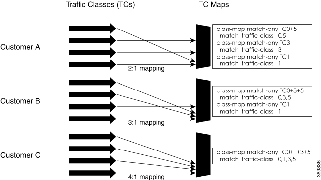
Let us consider an example where three customers have purchased these services, based on their requirements:
Customer A - Requires RT traffic, reserved BW traffic and BE traffic delivery.
Customer B – Requires reserved BW traffic and BE traffic delivery.
Customer C – Needs only BE traffic delivery.
Using the selective egress policy-based queue mapping, you can create three profiles this way:
Customer A – Priority queue RT traffic (TC1), Guaranteed BW traffic (TC3), Best effort traffic (TC0, TC5)
Customer B – Guaranteed BW traffic (TC1), Best effort traffic (TC0, TC3, TC5)
Customer C - Best effort traffic (TC0, TC1, TC3, TC5)
Using the egress TC-mapping, you can create three different profiles that you can use for each customer based on their SLAs with the provider.
Ensure that you read these points before you configure the selective egress policy-based queue-mapping feature.
There can be only one TC (Traffic Class) mapped class to a PM (Policy Map).
You cannot use a TC that you used in a mapped class, in a non-mapped class under the same PM.
You can have a maximum of three unique TC mapped PMs or profiles per platform.
Every TC mapped class must include traffic-class 0 in the range values.
The TC-mapping range is from 0 through 5.
When a TC-mapped class is present in a PM, the class default becomes a dummy class. This means that the class default statistics and QoS values are not applicable.
All the class default limitations apply to the TC-mapped class; for example, you cannot configure priority command under the TC mapped class.
Note |
A TC-mapped PM or profile is a PM that contains a TC-mapped class. Example of a TC-mapped class: match traffic-class 0 1 2 3 Example of a TC non-mapped class: match traffic-class 1 |
This section details a sample configuration for the selective egress policy-based queue-mapping feature and a use case to show how this feature works.
Sample configuration
class-map match-any <name>
 match traffic-class <value>
commit

policy-map tc_pmap
 class tc035
  shape average percent 1
 !
 class class-default
!
 end-policy-map
!
 class-map match-any tc035
match traffic-class 0 3 5
 end-class-map
!
Run the show qos interface and show policy-map interface commands.
When TC mapping class is present in a policy map, the class default does not have any values calculated.
show qos interface bundle-Ether 44 output sample
NOTE:- Configured values are displayed within parentheses
NPU Id:                        0
Total number of classes:       3
Interface Bandwidth:           100000000 kbps
Policy Name:                   tc_pmap
Accounting Type:               Layer1 (Include Layer 1 encapsulation and above)
------------------------------------------------------------------------------
Level1 Class                             =   tc1

Level1 Class                             =   tc035

Level1 Class                             =   class-default

Interface HundredGigE0/0/0/30 Ifh 0xf000208 (Member) -- output policy
NPU Id:                        0
Total number of classes:       3
Interface Bandwidth:           100000000 kbps
Policy Name:                   tc_pmap
VOQ Base:                      1264
Accounting Type:               Layer1 (Include Layer 1 encapsulation and above)
------------------------------------------------------------------------------
Level1 Class                             =   tc1
Egressq Queue ID                         =   1265 (LP queue)
Queue Max. BW.                           =   10063882 kbps (10 %)
Queue Min. BW.                           =   0 kbps (default)
Inverse Weight / Weight                  =   1 / (BWR not configured)
Guaranteed service rate                  =   10000000 kbps
TailDrop Threshold                       =   12517376 bytes / 10 ms (default)
WRED not configured for this class

Level1 Class                             =   tc035
Egressq Queue ID                         =   1264 (LP queue)
Queue Max. BW.                           =   1011732 kbps (1 %)
Queue Min. BW.                           =   0 kbps (default)
Inverse Weight / Weight                  =   1 / (BWR not configured)
Guaranteed service rate                  =   1000000 kbps
TailDrop Threshold                       =   1253376 bytes / 10 ms (default)
WRED not configured for this class

Level1 Class                             =   class-default
Queue Max. BW.                           =   no max (default)
Queue Min. BW.                           =   0 kbps (default)
Inverse Weight / Weight                  =   0 / (BWR not configured)
show policy-map interface bundle-Ether 44 output sample
Bundle-Ether44 output: tc_pmap

Class tc1
  Classification statistics          (packets/bytes)     (rate - kbps)
    Matched             :              429444/53823648             0
    Transmitted         :              429444/53823648             0
    Total Dropped       :                   0/0                    0
  Queueing statistics
    Queue ID                             : None (Bundle)
    Taildropped(packets/bytes)           : 0/0
Class tc035
  Classification statistics          (packets/bytes)     (rate - kbps)
    Matched             :             1288331/161470820            0
    Transmitted         :             1288331/161470820            0
    Total Dropped       :                   0/0                    0
  Queueing statistics
    Queue ID                             : None (Bundle)
    Taildropped(packets/bytes)           : 0/0
Class class-default
  Classification statistics          (packets/bytes)     (rate - kbps)
    Matched             :                   0/0                    0
    Transmitted         :                   0/0                    0
    Total Dropped       :                   0/0                    0
  Queueing statistics
    Queue ID                             : None (Bundle)
    Taildropped(packets/bytes)           : 0/0
Policy Bag Stats time: 1557216940000  [Local Time: 05/07/19 08:15:40.000]
RP/0/RP0/CPU0:BB1#
With the ingress traffic matching the same match criteria, you can group the egress traffic up to three unique TC mapped profiles. Using this feature, you can provide differentiated services to customers based on the SLAs they have signed up for.
In the example that follows, the ingress policy-map sets the ingress match criteria for the traffic class from 0 through 5. Based on the SLAs, you can group the TC values at the egress PM to deliver differentiated services.
After you group the TC values, you can apply specific egress actions under that class.
Ingress match:
class EXP1
  set traffic-class 1
!
class EXP2
  set traffic-class 2
!
class EXP3
  set traffic-class 3
!
class EXP4
  set traffic-class 4
!
class EXP5
  set traffic-class 5
!
class class-default
!
end-policy-map
!
Egress match:
Sample TC mapped class for policy-map PM1
class-map match-any TC2:1
match traffic-class 0 1
end-class-map
Sample TC mapped class for policy-map PM2
class-map match-any TC3:1
match traffic-class 0 1 2
end-class-map
Sample TC mapped class for policy-map PM3
class-map match-any TC6:1
match traffic-class 0 1 2 3 4 5
end-class-map
You can create QoS groups and configure ACLs to classify traffic into the groups based on a specified match condition. In this example, we match by the QoS group value (0-511).
Before you can configure QoS groups with an ACL, the QoS peering profile must be enabled on the router or the line card. After enabling QoS peering, the router or line card must be reloaded, as shown in the following configuration.
Note |
If you enable QoS peering, the Source-based RTBH (S-RTBH) feature will not be supported due to hardware limitations related to copy engine availability. |
Enter the global configuration mode and enable the QoS peering profile for the router as shown:
RP/0/RP0/CPU0:router(config)# hw-module profile qos ingress-model peering
RP/0/RP0/CPU0:router(config)# exit
RP/0/RP0/CPU0:router# reload
Enter the global configuration mode and enable the QoS peering profile for the line card as shown:
RP/0/RP0/CPU0:router(config)# hw-module profile qos ingress-model peering location 0/0/CPU0
RP/0/RP0/CPU0:router(config)# exit
RP/0/RP0/CPU0:router# reload location 0/0/CPU0
Use the following set of configuration statements to configure an ACL with QoS groups.
/*
 Enter the global configuration mode, and configure an ACL with the required QoS groups. */
RP/0/RP0/CPU0:router# configure
RP/0/RP0/CPU0:router(config)# ipv4 access-list qos-acl
RP/0/RP0/CPU0:router(config-ipv4-acl)# 10 permit ipv4 host 5.0.0.1 any set qos-group 1
RP/0/RP0/CPU0:router(config-ipv4-acl)# 11 permit ipv4 host 6.0.0.1 any set qos-group 2
RP/0/RP0/CPU0:router(config-ipv4-acl)# 12 permit ipv4 host 7.0.0.1 any set qos-group 3
RP/0/RP0/CPU0:router(config-ipv4-acl)# 13 deny ipv4 any any


/* Create a policy map with the required classes.
In this example, we also create a default class for traffic that does not belong to any of the specified
classes. */
RP/0/RP0/CPU0:router(config)# policy-map qos-acl-map
RP/0/RP0/CPU0:router(config-pmap)# class qos1
RP/0/RP0/CPU0:router(config-pmap-c)# set dscp af43
RP/0/RP0/CPU0:router(config-pmap-c)# set traffic-class 2
RP/0/RP0/CPU0:router(config-pmap-c)# exit

RP/0/RP0/CPU0:router(config-pmap)# class qos2
RP/0/RP0/CPU0:router(config-pmap-c)# set precedence critical
RP/0/RP0/CPU0:router(config-pmap-c)# set traffic-class 7
RP/0/RP0/CPU0:router(config-pmap-c)# exit

RP/0/RP0/CPU0:router(config-pmap)# class qos3
RP/0/RP0/CPU0:router(config-pmap-c)# set precedence 2
RP/0/RP0/CPU0:router(config-pmap-c)# set traffic-class 2
RP/0/RP0/CPU0:router(config-pmap-c)# exit

RP/0/RP0/CPU0:router(config-pmap)# class qos4
RP/0/RP0/CPU0:router(config-pmap-c)# set traffic-class 4
RP/0/RP0/CPU0:router(config-pmap-c)# set dscp cs4
RP/0/RP0/CPU0:router(config-pmap-c)# exit

RP/0/RP0/CPU0:router(config-pmap)# class class-default
RP/0/RP0/CPU0:router(config-pmap-c)# police rate percent 20
RP/0/RP0/CPU0:router(config-pmap-c-police)# exit


/* Create the class maps for specifying the match conditions. */
RP/0/RP0/CPU0:router(config)# class-map match-any qos1
RP/0/RP0/CPU0:router(config-cmap)# match qos-group 1
RP/0/RP0/CPU0:router(config-cmap)# end-class-map

RP/0/RP0/CPU0:router(config)# class-map match-any qos2
RP/0/RP0/CPU0:router(config-cmap)#  match qos-group 2
RP/0/RP0/CPU0:router(config-cmap)# end-class-map

RP/0/RP0/CPU0:router(config)# class-map match-any qos3
RP/0/RP0/CPU0:router(config-cmap)# match qos-group 3
RP/0/RP0/CPU0:router(config-cmap)# end-class-map

RP/0/RP0/CPU0:router(config)# class-map match-any qos4
RP/0/RP0/CPU0:router(config-cmap)# match qos-group 4
RP/0/RP0/CPU0:router(config-cmap)# end-class-map


/* Apply the access list and the QoS map to the Gigabit interface, and commit your configuration. */
RP/0/RP0/CPU0:router(config)# interface TenGigE0/0/0/1
RP/0/RP0/CPU0:router(config-if)# ipv4 address 12.0.0.1/24
RP/0/RP0/CPU0:router(config-if)# no shut
RP/0/RP0/CPU0:router(config-if)# service-policy input qos-acl-map
RP/0/RP0/CPU0:router

RP/0/RP0/CPU0:router(config-if)# commit
Tue Mar 28 10:23:34.106 IST

RP/0/0/CPU0:Mar 28 10:37:48.570 : ifmgr[397]: %PKT_INFRA-LINK-3-UPDOWN : Interface TenGigE0/0/0/1, changed state to Down
RP/0/0/CPU0:Mar 28 10:37:48.608 : ifmgr[397]: %PKT_INFRA-LINK-3-UPDOWN : Interface TenGigE0/0/0/1, changed state to Up

RP/0/RP0/CPU0:router(config-if)# exit
Confirm your configuration.
RP/0/RP0/CPU0:router(config)# show run
Tue Mar 28 10:37:55.737 IST

Building configuration...
!! IOS XR Configuration 0.0.0

ipv4 access-list qos-acl
10 permit ipv4 host 5.0.1.1 any set qos-group 1
11 permit ipv4 host 6.0.1.1 any set qos-group 2
12 permit ipv4 host 7.0.1.1 any set qos-group 3
13 deny ipv4 any any

class-map match-any qos1
match qos-group 1
end-class-map
!
class-map match-any qos2
match qos-group 2
end-class-map
!
class-map match-any qos3
match qos-group 3
end-class-map
!
class-map match-any qos4
match qos-group 4
end-class-map
!

policy-map qos-acl-map
class qos1
  set dscp af43
  set traffic-class 2
!
class qos2
  set precedence critical
  set traffic-class 7
!
class qos3
  set precedence 2
  set traffic-class 2
!
class qos4
  set traffic-class 4
  set dscp cs4
!
class class-default
  police rate percent 20
  !
!
end-policy-map
!

interface TenGigE0/0/0/1
service-policy input qos-acl-map
ipv4 address 12.0.0.1 255.255.255.0
ipv4 access-group qos-acl ingress compress level 3

!
You have successfully configured an ACL with QoS groups.
To achieve QoS Egress marking/queuing, the router utilizes the dual policy model on the Egress with independent policies for marking and queuing.
Egress marking can be achieved by applying a policy-map on the ingress interface by setting qos-group/discard-class. Then the qos-group which is set by the ingress policy-map is used by the egress-policy map along with DP (drop-precedence or discard class) value to remark the cos/dei bits of the outgoing L2 packet. Similarly Egress queuing can be achieved by applying a policy-map on the ingress interface by setting the traffic-class. Then the traffic-class is used by the egress-policy map to perform queuing actions.
This feature enables the users to make the marking decision based on the DP (drop precedence) field.
In case of MPLS-to-Layer 2 traffic stream, the Layer 2 packet is within the MPLS data packet; therefore marking of the Layer 2 header is possible only at Egress after data transmission.
In case of Egress rewrite operations, where the VLAN tags are modified or added, the cos or the dei fields can be marked with Egress marking.
QoS Egress Marking and Queueing can be summarized in the following three steps—
Configure a Ingress Policy-Map— classifying the incoming packet and setting the qos-group/discard-class or the traffic class.
Configure a Egress Policy-Map:
Configure Egress Marking Policy—
Create class-map to classify on qos-group/discard-class.
Create policy-map to mark cos/dei field in the L2 header.
Configure Egress Queuing Policy—
Create class-map to classify on traffic-class.
Create policy-map to perform the queuing actions (for example, bandwidth, shaping, priority).
Attaching the policies to the Interfaces.
Note |
While marking QinQ traffic, only outer dot1q header is effected and the inner header remains as is. However, in case of few rewrite operations where the new QinQ tags are added, the inner header is marked. |
/*Create class-map/*
Router#config
Router(config)#class-map match-any cos2
Router(config-cmap)#match cos 2
Router(config-cmap)#commit
Router(config)#class-map match-any cos3
Router(config-cmap)#match cos 3
Router(config-cmap)#commit
Router(config)#class-map match-any cos4
Router(config-cmap)#match cos 4
Router(config-cmap)#commit

/*Create classification policies*/
Router#config
Router(config)#policy-map ingress-classification
Route(config-pmap)#class cos2
Router(config-pmap-c)#set qos-group 1
Router(config-pmap-c)#set traffic-class 3
Router(config-pmap-c)#class cos3
Router(config-pmap-c)#set qos-group 2
Router(config-pmap-c)#set traffic-class 5
Router(config-pmap-c)#class cos4
Router(config-pmap-c)#set qos-group 3
Router(config-pmap-c)#set traffic-class 4
Router(config-pmap-c)#class class-default
Router(config-pmap-c)#set qos-group 7
Router(config-pmap-c)#set traffic-class 6
Router(config-pmap-c)#commit*/Egress Marking Policy/*
Router#config
Router(config)#class-map match-any qos1
Router(config-cmap)#match qos-group 1
Router(config-cmap)#commit
Router(config)#class-map match-any qos2
Router(config-cmap)#match qos-group 2
Router(config-cmap)#commit
Router(config)#class-map match-any qos3
Router(config-cmap)#match qos-group 3
Router(config-cmap)#commit
Router#config
Router(config)#policy-map egress-marking
Route(config-pmap)#class qos1
Router(config-pmap-c)#set cos 1
Router(config-pmap-c)#class qos2
Router(config-pmap-c)#set cos 2
Router(config-pmap-c)#set dei 1
Router(config-pmap-c)#class qos3
Router(config-pmap-c)#set cos 3
Router(config-pmap-c)#class class-default
Router(config-pmap-c)#set cos 7
Router(config-pmap-c)#commit
*/Egress Queuing Policy/*
Router#config
Router(config)#class-map match-any tc3
Router(config-cmap)#match traffic-class 3
Router(config-cmap)#commit
Router(config)#class-map match-any tc4
Router(config-cmap)#match traffic-class 3
Router(config-cmap)#commit
Router(config)#class-map match-any tc5
Router(config-cmap)#match traffic-class 3
Router(config-cmap)#commit
Router#config
Router(config)#policy-map egress-queuing
Route(config-pmap)#class tc3
Router(config-pmap-c)#shape average 2 mbps
Router(config-pmap-c)#class tc4
Router(config-pmap-c)#shape average 5 mbps
Router(config-pmap-c)#class tc5
Router(config-pmap-c)#shape average 7 mbps
Router(config-pmap-c)#class class-default
Router(config-pmap-c)#commit
Router#config
Router(config)#interface tenGigE 0/0/0/1
Router(config-if)#service-policy input ingress-classification
Router(config-if)#service-policy output egress-marking
Router(config-if)#service-policy output egress-queuing
Router(config-if)#commit
Statistics for marking policy is not supported, that is, the show policy-map interface command does not display any output.
Statistics output is displayed only when the queuing policy is applied.
Egress marking policy can classify only on qos-group/discard-class.
Egress queueing policy can classify only on traffic-class.
Egress marking policy can mark only the cos/dei field in L2 header.
Note |
If you apply an ingress policy map to a bundle that has bundle members only from a single core of an NPU, the QoS resources are consumed on both cores of that NPU. |
Other restrictions to follow:
If you have a set traffic class statement explicitly configured in the ingress service policy, it’s mandatory to have a corresponding match traffic class on egress for the traffic to be correctly matched and the stats to be accounted in show policy-map interface <> output command. To match the ingress traffic to the egress class-default, traffic class should be set to 0 on ingress.
If you have a set traffic class that is configured in ingress service policy, and no corresponding match traffic class on egress, the traffic won’t go to class default and the stats for this traffic flow won’t be seen in show policy-map interface <> output command.
If you don’t have any set traffic class statement in ingress, then traffic will hit the default-class on egress.
If you have a set discard-class statement configured in the ingress service policy, it’s mandatory to have a corresponding match discard-class on egress for the traffic to be correctly matched and the stats to be accounted in show policy-map interface <> output command.
If you have a set discard-class statement configured in the ingress service policy and don’t have a corresponding match discard-class on egress, the traffic won’t hit the class-default and the stats for this flow won’t be accounted in show policy-map interface <> output command.
The system doesn’t support class-map size on peering mode.
Depending on the packet size, the traffic shaped value for low shaper rates, such as 10mbps, have greater deviation than 5% of tolerance from the shaper value. For higher shaper rates, the deviation is within the limit of 5% of tolerance from the shaper value for all packet sizes.
After enabling the QoS peering feature using the hw-module profile qos ingress-model peering command, you can set the Layer 2 class of service (CoS) or drop eligible indicator (DEI) values at the egress using the set cos or set dei commands, respectively. However, at the egress, ensure that you don’t set the MPLS experimental imposition (EXP) values (using the set mpls experimental imposition command). Otherwise, when committing the policy map with these configurations at the egress, you will encounter an error. This error occurs because the internal fields required for egress EXP marking are not available with peering enabled.
explicit set discard-class statement isn’t supported.
This feature is supported only on L3 interfaces and is limited to 1000 L3 interfaces per system.
set mpls exp topmost statement isn’t supported within QoS in peering mode.
access group statement isn’t supported.
(Only in Release 6.2.x and Release 6.3.x) set mpls exp imposition statement isn’t supported on ingress interface.
2-Level ingress policers isn’t supported.
(From Release 6.5.x) Egress H-QOS with peering profile support is enabled, but ingress H-QOS with peering profile isn’t supported.
Depending on the packet size, the traffic shaped value for low shaper rates, such as 10mbps, have greater deviation than 5% of tolerance from the shaper value. For higher shaper rates, the deviation is within the limit of 5% of tolerance from the shaper value for all packet sizes.
The system doesn’t support the egress policy on Bridge-Group Virtual Interface (BVI), but BVI (CoS, DEI) marking is supported by applying the policy to its corresponding Layer 2 interface, which is part of the same bridge domain.
If you apply L3 ingress QoS policy on L2 interface, which is a part of the same bridge-domain as BVI, the classification might not work if packets are destined to the BVI MAC address.
If a QoS policy is attached to BVI, the policy is inherited by the L2 interfaces, which are part of the same bridge-domain. Hence, any other policy can’t be applied on the L2 interfaces. Similarly, if a QoS policy is attached to any of the L2 interfaces, any QoS policy can’t be applied on the BVI, which is part of the same bridge-domain.
In the two-pass forwarding model for packets from Layer 2 to Layer 3 over BVI, where Layer 2 and Layer 3 forwarding are split across two paths and packet processing happens in two cycles, you can apply separate QoS policies for Layer 2 and BVI interfaces.
A maximum of 8 interfaces can have the drop action configured and a maximum of 8 classes in any single policy can have the drop action.
A drop action in any particular class can’t be combined with other actions.
Drop action in a policy applied on the main interface isn’t inherited onto sub-interfaces.
Match condition for drop action PM can only be based on qos-group, discard class based match isn’t supported.
The In-Place policy modification feature allows you to modify a QoS policy even when the QoS policy is attached to one or more interfaces. A modified policy is subjected to the same checks that a new policy is subject to when it is bound to an interface. If the policy-modification is successful, the modified policy takes effect on all the interfaces to which the policy is attached. However, if the policy modification fails on any one of the interfaces, an automatic rollback is initiated to ensure that the pre-modification policy is in effect on all the interfaces.
You can also modify any class map used in the policy map. The changes made to the class map take effect on all the interfaces to which the policy is attached.
Note |
|
Note |
|
If unrecoverable errors occur during in-place policy modification, the policy is put into an inconsistent state on target interfaces. No new configuration is possible until the configuration session is unblocked. It is recommended to remove the policy from the interface, check the modified policy and then re-apply accordingly.
References for Modular QoS Service Packet Classification
Use of IP precedence allows you to specify the CoS for a packet. You can create differentiated service by setting precedence levels on incoming traffic and using them in combination with the QoS queuing features. So that, each subsequent network element can provide service based on the determined policy. IP precedence is usually deployed as close to the edge of the network or administrative domain as possible. This allows the rest of the core or backbone to implement QoS based on precedence.

You can use the three precedence bits in the type-of-service (ToS) field of the IPv4 header for this purpose. Using the ToS bits, you can define up to eight classes of service. Other features configured throughout the network can then use these bits to determine how to treat the packet in regard to the ToS to grant it. These other QoS features can assign appropriate traffic-handling policies, including congestion management strategy and bandwidth allocation. For example, queuing features such as LLQ can use the IP precedence setting of the packet to prioritize traffic.
Use the three IP precedence bits in the ToS field of the IP header to specify the CoS assignment for each packet. You can partition traffic into a maximum of eight classes and then use policy maps to define network policies in terms of congestion handling and bandwidth allocation for each class.
Each precedence corresponds to a name. IP precedence bit settings 6 and 7 are reserved for network control information, such as routing updates. These names are defined in RFC 791.
By default, the routers leave the IP precedence value untouched. This preserves the precedence value set in the header and allows all internal network devices to provide service based on the IP precedence setting. This policy follows the standard approach stipulating that network traffic should be sorted into various types of service at the edge of the network and that those types of service should be implemented in the core of the network. Routers in the core of the network can then use the precedence bits to determine the order of transmission, the likelihood of packet drop, and so on.
Because traffic coming into your network can have the precedence set by outside devices, we recommend that you reset the precedence for all traffic entering your network. By controlling IP precedence settings, you prohibit users that have already set the IP precedence from acquiring better service for their traffic simply by setting a high precedence for all of their packets.
The class-based unconditional packet marking and LLQ features can use the IP precedence bits.
If you need to mark packets in your network and all your devices support IP DSCP marking, use the IP DSCP marking to mark your packets because the IP DSCP markings provide more unconditional packet marking options. If marking by IP DSCP is undesirable, however, or if you are unsure if the devices in your network support IP DSCP values, use the IP precedence value to mark your packets. The IP precedence value is likely to be supported by all devices in the network.
You can set up to 8 different IP precedence markings and 64 different IP DSCP markings.
Conditional marking of MPLS EXP bits is supported on Virtual Private Wire Service (VPWS), Virtual Private LAN Service (VPLS) and Ethernet Virtual Private Network (EVPN) traffic in the L2VPN network.
The conditional marking of MPLS experimental bits is achieved for Layer 2 Virtual Private Network (L2VPN) traffic by applying a combination of ingress and egress policy-maps on the Provider Edge (PE) router. In the ingress policy-map, the qos-group or discard-class is set either based on the result of the policing action or implicitly. The egress policy-map matches on qos-group or on a combination of qos-group and discard-class and sets the mpls experiment bits to the corresponding value.
Conditional marking can be used to mark the MPLS experimental bits differently for in-contract and out-of-contract packets. In-contract packets are the confirmed packets with the color green and discard-class set to 0. Out-of-contract packets are the packets which have exceeded the limit and have the color yellow and discard-class set to 1.
Conditional marking of MPLS experimental bits for L2VPN traffic is supported on both physical and bundle main interfaces as well as sub-interfaces.
Conditional marking of MPLS EXP bits is not supported for broadcast, unknown unicast and multicast (BUM) traffic.
In the case of two PE routers connected back-to-back and the only label that the traffic between the routers have is the BGP label, then the explicit null label should be configured.
A maximum of two policy-maps which perform conditional marking of MPLS experimental bits can be configured per Network Processor Unit (NPU) of the Cisco NCS 560 Series Routers. However, the same policy can be applied on multiple interfaces on the same NPU.
In the ingress policy-map if qos-group is being set for the incoming traffic packets, then setting of dscp and mpls experimental bits will not work.
Both the ingress and egress policy-maps must be applied in order to attain the expected behaviour. If either one of them is not applied then it may lead to undefined behaviour.
If the egress policy-map does not match on qos-group or discard-class and set the mpls experiment bits to the required value, then the mpls experimental bits will be set to a value of zero, by default.
|
Feature Name |
Release Information |
Feature Description |
|---|---|---|
|
QoS IP DSCP Preservation for SR-TE |
Release 7.7.1 |
In terms of preserving IP DSCP markings, this release covers two scenarios for SR-TE traffic:
With preservation, traffic with IP packets with DSCP marking for priority, flows as intended and there’s no drop in traffic because of incorrect or missing labels. In previous releases, irrespective of the number of MPLS labels, when the EXP values were copied into the packet header during imposition, even the IP DSCP markings were modified. This modification resulted in traffic drops at the next-hop routers in SR-TE tunnels. This feature introduces the hw-module profile mpls-ext-dscp-preserve command. |
A typical ingress scenario for SR-TE traffic involves:
Specifying DSCP values as match criteria for a class map.
Identifying specific three-bit experimental bits (EXP) field values (also called Traffic Class or TC values, as per RFC 5462) in the topmost MPLS label as match criteria for the same class map.
When the MPLS labels are pushed (also called imposition) into the packet, the EXP values are copied into the EXP field in the packet header. At this stage, for SR-TE traffic, even the DSCP values that you set initially are modified, which could cause traffic drops at the next-hop router.
It is this behavior that the QoS DSCP preservation for SR-TE functionality mitigates. To enable this functionality, configure the hw-module profile mpls-ext-dscp-preserve command. This configuration ensures that the IP DSCP values are preserved for SR-TE traffic.
Note |
Ensure that you restart the router for the configuration to take effect. |
Here's a quick look at what the QoS DSCP preservation for SR-TE functionality achieves.
|
Scenario |
What was happening in previous releases? |
What's happening now? |
|---|---|---|
|
SR-TE cases |
Irrespective of the number of MPLS labels (1, 2, … 12) for imposition, the push action modified IP DSCP values. |
|
|
SR Topology-Independent Loop-Free Alternate (TI-LFA) cases |
For three MPLS labels for imposition, the push action modified IP DSCP values. |
Irrespective of the number of MPLS labels, IP DSCP values are preserved when you configure the hw-module profile mpls-ext-dscp-preserve command. |
Disabling the propagation of IP Time-To-Live (TTL) to and from the MPLS header (using the mpls ip-ttl-propagate command) doesn't help preserve IP DSCP values for SR-TE traffic. This is because the IP TTL acts on the egress, while the DSCP preservation for SR-TE is for the ingress traffic.
When you use the on-demand steering command to disable labeled services for SR-TE policies, your router supports 12 MPLS transport labels by default. With the QoS DSCP preservation for SR-TE functionality enabled, this default value changes to ten MPLS transport labels.
By default, SR-TE (with steering services enabled) supports 2 service labels and 9 transport labels. This support changes to 2 service labels and 8 transport labels when you configure hw-module profile mpls-ext-dscp-preserve .
This functionality doesn’t work for SR-TE traffic associated with Binding Single-ID (BSID) policy paths. This is because packets with BSID labels get terminated, and new SR-TE labels get pushed, modifying the IP DSCP values. Thus, for BSID traffic (labeled traffic), disabling the propagation of IP TTL (using mpls ip-ttl-propagate ) or configuring the hw-module profile mpls-ext-dscp-preserve command to enable QoS DSCP preservation for SR-TE doesn't help in IP DSCP preservation.
This functionality isn't applicable for routers that have line cards installed and operating in native and compatibility modes. For these routers, DSCP preservation is by default, irrespective of the number of labels for both SR TI-LFA and SR-TE cases.
The hw-module profile sr-policy v6-null-label-autopush and hw-module profile mpls-ext-dscp-preserve commands are mutually exclusive.
On Cisco NCS 560 Series Routers, this feature isn't supported on channelized ports.
To configure QoS IP DSCP preservation for SR-TE:
Router(config)#class-map
Router(config)#class-map match-any  exp_policy
Router(config-cmap)#match dscp cs2
Router(config-cmap)#end-class-map
Router(config)#
Router(config)#policy-map exp_policy
Router(config-pmap)#class exp_policy
Router(config-pmap-c)#set mpls experimental imposition 7
Router(config-pmap-c)#set traffic-class 7
Router(config-pmap-c)#commit
Apply the policy on the ingress interface.
Router(config)#interface TenGigE0/0/0/0
Router(config-if)#service-policy input exp_policy
Router(config-if)#ipv4 address 192.0.2.1 255.255.255.0
Router(config-if)#commit
Nexthop reachability for ingress traffic is through SR-TE Tunnels. To configure SR-TE policies, see Configure SR-TE Policies in the Segment Routing Configuration Guide for Cisco NCS 560 Series Routers.
Configure the DSCP preservation for IPv4 SR-TE traffic and reload the chassis for the configuration to take effect.
Router#config
Router(config)#hw profile mpls-ext-dscp-preserve v4uc-enable

Router(config)#commit
Router(config)#exit
Router#reload location allclass-map
class-map match-any exp_policy
match dscp cs2
end-class-map
!
policy-map
policy-map exp_policy
class exp_policy
set mpls experimental imposition 7
set traffic-class 7
!
interface TenGigE0/0/0/0
service-policy input exp_policy
ipv4 address 192.0.2.1 255.255.255.0
!
hw profile mpls-ext-dscp-preserve v4uc-enable
!Verify that you have successfully configured DSCP preservation for IPv4 SR-TE traffic
Run the command show controller fia diagshell 0 "config" location 0/0/cpu0 | i dscp and in the output, verify that custom_feature_dscp_preserve_with_extend_label equals 1. The value is 1 only when the hw profile mpls-ext-dscp-preserve v4uc-enable command takes effect after router reload.
Router#show controller fia diagshell 0 "config" location 0/0/cpu0 | inc dscp_preserve
custom_feature_dscp_preserve_with_extend_label_v6=1 The incoming packets on the Power Edge router are classified based on the ingress policy-map and these actions are taken.
Set qos-group
Discard class or drop precedence is set implicitly or as a result of a policing action.
Set traffic class
Packets that violate the configured policer are dropped in the ingress processing itself.
class-map af11
   match cos 1
!

policy-map ingress
 class af11
  police rate percent 10 peak-rate percent 20
  !
  set qos-group 1
  set Traffic-class 3
 !
 class class-default
 !
 end-policy-map
!
The ingress packet undergoes MPLS encapsulation during the egress processing in the PE router which performs the label imposition. The MPLS experimental bits are marked on the basis of egress policy-map which performs the following actions:
Match on qos-group or discard class or both
Set the MPLS experimental bits based on the match criteria
class-map match-all qos-group2_0
   match qos-group 2
   match discard-class 0

policy-map egress-marking
 class qos-group2_0 # This class matches on qos-group 2 and discard-class 0
  set mpls experimental imposition 1
 !
 class class-default
 !
 end-policy-map
!
policy-map Egress-Queuing
 class Traffic-class3
  shape average 500 mbps
!
 class class-default
!
end-policy-map
!
|
Feature Name |
Release Information |
Feature Description |
|
Conditional Marking of MPLS Experimental Bits for EVPN-VPWS Single-Homing Services |
Release 7.3.1 |
This feature enables you to differentiate traffic in the MPLS forwarding domain and manage traffic from ingress PE to egress PE based on the MPLS EXP bit of the MPLS header. This feature is supported only for EVPN-VPWS single-homing services, and not supported for EVPN-VPWS multi-homing services. |
The conditional marking of MPLS experimental bits is achieved for EVPN-VPWS single-homing services by applying a combination of ingress and egress policy-maps on the provider edge (PE) router. In the ingress policy-map, the qos-group or discard-class is set either based on the result of the policing action or implicitly. The egress policy-map matches on qos-group or on a combination of qos-group and discard-class and sets the MPLS experiment bits to the corresponding value.
Conditional marking can be used to mark the MPLS experimental bits differently for in-contract and out-of-contract packets. In-contract packets are the confirmed packets with the color green and discard-class set to 0. Out-of-contract packets are the packets that have exceeded the limit and have the color yellow and discard-class set to 1.
Conditional marking of MPLS experimental bits for EVPN-VPWS single-homing services are supported on both physical and bundle main interfaces as well as sub-interfaces.
|
Feature Name |
Release Information |
Feature Description |
|
MPLS EXP Marking for EVPN Multi-Homed Services |
Release 7.6.1 |
You can now differentiate traffic in the MPLS forwarding domain and manage traffic from ingress PE to egress PE based on the MPLS EXP bit of the MPLS header for EVPN multi-home scenarios. |
Note |
This feature is not supported on routers that have the Cisco NC57 line cards installed and operate in the native mode or compatibility mode. |
The ingress policing is applied on the UNI interface. It is with set qos-group and set traffic class.
The marking policy is applied at the core facing NNI interface.
MPLS EXP imposition is marked while packets egress from NNI Interface.
interface TenGigE0/0/0/2.203 l2transport  => This is UNI
encapsulation dot1q 203
service-policy input pol50-100

interface TenGigE0/0/0/10  ===============> This is the core NNI
description *** CORE IF  ***
cdp
service-policy input in_mpls
service-policy output eg_mark
ipv4 address 192.18.44.18 255.255.255.0
ipv6 address 2005:18:44::18/48
lldp
  enable
!
monitor-session test ethernet direction tx-only port-level
!
load-interval 30
!
l2vpn
xconnect group 203
  p2p 203
   interface TenGigE0/0/0/2.203
   neighbor evpn evi 1 service 203

policy-map pol50-100
class class-default
  set traffic-class 2
  set qos-group 4
  police rate 50 mbps peak-rate 100 mbps
  !
!
end-policy-map
!

policy-map eg_mark
class qg4dc0
  set mpls experimental imposition 2
!
class qg4dc1
 set mpls experimental imposition 3
!
class class-default
!
end-policy-map
!
class-map match-all qg4dc0
match qos-group 4
match discard-class 0
end-class-map
!

class-map match-all qg4dc1
match qos-group 4
match discard-class 1
end-class-map
Verify that you have configured conditional marking of MPLS experimental bits for EVPN-VPWS single-homing services successfully.
Router#show qos int tenGigE 0/0/0/2.101 input
NOTE:- Configured values are displayed within parentheses
Interface TenGigE0/0/0/2.101 ifh 0x41da  -- input policy
NPU Id:                        0
Total number of classes:       1
Interface Bandwidth:           10000000 kbps
Policy Name:                   pol50-100
Accounting Type:               Layer1 (Include Layer 1 encapsulation and above)
------------------------------------------------------------------------------
Level1 Class                             =   class-default
New traffic class                        =   2
New qos group                            =   4

Policer Bucket ID                        =   0x18
Policer Stats Handle                     =   0x0
Policer committed rate                   =   49219 kbps (50 mbits/sec)
Policer peak rate                        =   98438 kbps (100 mbits/sec)
Policer conform burst                    =   62336 bytes (default)
Policer exceed burst                     =   187008 bytes (default)
-------------------------------------------------------------------------------

Router#show qos int tenGigE 0/0/0/10 output
Tue Sep  1 04:18:27.508 UTC
NOTE:- Configured values are displayed within parentheses
Interface TenGigE0/0/0/10 ifh 0xe0  -- output policy
NPU Id:                        0
Total number of classes:       3
Interface Bandwidth:           10000000 kbps
Policy Name:                   eg_mark
VOQ Base:                      0
Accounting Type:               Layer1 (Include Layer 1 encapsulation and above)
------------------------------------------------------------------------------
Level1 Class                             =   qg4dc0
New imposition exp                       =   2
Queue Max. BW.                           =   no max (default)
Queue Min. BW.                           =   0 kbps (default)
Inverse Weight / Weight                  =   0 / (BWR not configured)

Level1 Class                             =   qg4dc1
New imposition exp                       =   3
Queue Max. BW.                           =   no max (default)
Queue Min. BW.                           =   0 kbps (default)
Inverse Weight / Weight                  =   0 / (BWR not configured)

Level1 Class                             =   class-default
Queue Max. BW.                           =   no max (default)
Queue Min. BW.                           =   0 kbps (default)
Inverse Weight / Weight                  =   0 / (BWR not configured)
------------------------------------------------------------------------------
|
Feature Name |
Release Information |
Feature Description |
|
MPLS EXP Marking for EVPN Multi-Homed Services |
Release 7.6.1 |
You can now differentiate traffic in the MPLS forwarding domain and manage traffic from ingress PE to egress PE based on the MPLS EXP bit of the MPLS header for EVPN multi-home scenarios. |
Note |
This feature is not supported on routers that have the Cisco NC57 line cards installed and operate in the native mode or compatibility mode. |
For configurations, see Conditional Marking of MPLS Experimental Bits for EVPN-VPWS Single-Homing Services section.
 Feedback