Implementing IP Service Level Agreements

IP Service Level Agreements (IP SLAs) is a portfolio of technologies embedded in most devices that run Cisco IOS XR Software, which allows the user to perform network assessments, verify quality of service (QoS), ease the deployment of new services, and assist administrators with network troubleshooting and so on.

This chapter provides information about this feature and the different steps involved in configuring it.

This chapter covers the following topics:

IP Service Level Agreements Technology Overview

IP SLA uses active traffic monitoring, which generates traffic in a continuous, reliable, and predictable manner to measure network performance. IP SLA sends data across the network to measure performance between multiple network locations or across multiple network paths. It simulates network data and IP services, and collects network performance information in real time. The following information is collected :

  • Response times

  • One-way latency, jitter (inter-packet delay variance)

  • Packet loss

  • Network resource availability

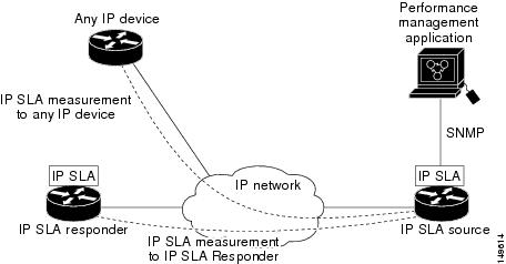
IP SLA performs active monitoring by generating and analyzing traffic to measure performance, either between the router or from a router to a remote IP device such as a network application server. Measurement statistics, which are provided by the various IP SLA operations, are used for troubleshooting, problem analysis, and designing network topologies.

This section covers the following topics:

Service Level Agreements

Internet commerce has grown significantly in the past few years as the technology has advanced to provide faster, more reliable access to the Internet. Many companies need online access and conduct most of their business on line and any loss of service can affect the profitability of the company. Internet service providers (ISPs) and even internal IT departments now offer a defined level of service—a service level agreement—to provide their customers with a degree of predictability.

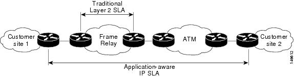
Network administrators are required to support service level agreements that support application solutions. Scope of Traditional Service Level Agreement Versus IP SLA shows how IP SLA has taken the traditional concept of Layer 2 service level agreements and applied a broader scope to support end-to-end performance measurement, including support of applications.


Note


  • Provided that the apllication and the IP-SLA processing rates support it, you can specify the flow rate for IP-SLA flow entries to up to 1500.

  • To enable high performance for IP-SLA operations, avoid reuse of same source and destination ports for multiple IP SLA operations on the same device, especially when the scale is huge


Figure 1. Scope of Traditional Service Level Agreement Versus IP SLA
Scope of Traditional Service Level Agreement Versus IP SLA

This table lists the improvements with IP SLA over a traditional service level agreement.

Table 1. IP SLA Improvements over a Traditional Service Level Agreement

Type of Improvement

Description

End-to-end measurements

The ability to measure performance from one end of the network to the other allows a broader reach and more accurate representation of the end-user experience.

Sophistication

Statistics, such as delay, jitter, packet sequence, Layer 3 connectivity, and path and download time, that are divided into bidirectional and round-trip numbers provide more data than just the bandwidth of a Layer 2 link.

Accuracy

Applications that are sensitive to slight changes in network performance require the precision of the submillisecond measurement of IP SLA.

Ease of deployment

Leveraging the existing Cisco devices in a large network makes IP SLA easier to implement than the physical operations that are often required with traditional service level agreements.

Application-aware monitoring

IP SLA can simulate and measure performance statistics generated by applications running over Layer 3 through Layer 7. Traditional service level agreements can measure only Layer 2 performance.

Pervasiveness

IP SLA support exists in Cisco networking devices ranging from low-end to high-end routers and switches. This wide range of deployment gives IP SLA more flexibility over traditional service level agreements.

Benefits of IP Service Level Agreements

This table lists the benefits of implementing IP SLA.

Table 2. List of Benefits for IP SLA

Benefit

Description

IP SLA monitoring

Provides service level agreement monitoring, measurement, and verification.

Network performance monitoring

Measure the jitter, latency, or packet loss in the network. In addition, IP SLA provides continuous, reliable, and predictable measurements along with proactive notification.

IP service network health assessment

Verifies that the existing QoS is sufficient for the new IP services.

Troubleshooting of network operation

Provides consistent, reliable measurement that immediately identifies problems and saves troubleshooting time.

Prerequisites for Implementing IP Service Level Agreements

Knowledge of general networking protocols and your specific network design is assumed. Familiarity with network management applications is helpful. We do not recommend scheduling all the operations at the same time as this could negatively affect your performance.

You must be in a user group associated with a task group that includes the proper task IDs. The command reference guides include the task IDs required for each command. If you suspect user group assignment is preventing you from using a command, contact your AAA administrator for assistance.

Restrictions for Implementing IP Service Level Agreements

  • The maximum number of IP SLA operations that is supported by Cisco IOS XR Software is 2048.

  • The maximum number of IP SLA configurable operations that is supported by Cisco IOS XR Software is 2000.

  • We do not recommend scheduling all the operations at the same start time as this may affect the performance. At the same start time, not more than 10 operations per second should be scheduled. We recommend using the start after configuration.


    Note


    Setting the frequency to less than 60 seconds will increase the number of packets sent. But this could negatively impact the performance of IP SLA operation when scheduled operations have same start time.
  • IP SLA is not HA capable.

  • Consider the following guidelines before configuring the frequency, timeout, and threshold commands.

    • Control disabled mode gives a better IP-SLA scale when compared to Control Enabled mode.

    Measuring Network Performance with IP Service Level Agreements

    IP SLA uses generated traffic to measure network performance between two networking devices, such as routers. IP SLA Operations shows how IP SLA starts when the IP SLA device sends a generated packet to the destination device. After the destination device receives the packet and if the operation uses an IP SLA component at the receiving end (for example, IP SLA Responder), the reply packet includes information about the delay at the target device. The source device uses this information to improve the accuracy of the measurements. An IP SLA operation is a network measurement to a destination in the network from the source device using a specific protocol, such as User Datagram Protocol (UDP) for the operation.

    Figure 2. IP SLA Operations
    IP SLA Operations

    To implement IP SLA network performance measurement, perform these tasks:

    1. Enable the IP SLA Responder, if appropriate.

    2. Configure the required IP SLA operation type.

    3. Configure any options available for the specified IP SLA operation type.

    4. Configure reaction conditions, if required.

    5. Schedule the operation to run. Then, let the operation run for a period of time to gather statistics.

    6. Display and interpret the results of the operation using Cisco IOS-XR Software CLI, XML, or an NMS system with SNMP.

    The following topics are covered in this section:

    IP SLA Responder and IP SLA Control Protocol

    The IP SLA Responder is a component embedded in the destination Cisco routing device that allows the system to anticipate and respond to IP SLA request packets. The IP SLA Responder provides enhanced accuracy for measurements. The patented IP SLA Control Protocol is used by the IP SLA Responder, providing a mechanism through which the responder is notified on which port it should listen and respond. Only a Cisco IOS-XR software device or other Cisco platforms can be a source for a destination IP SLA Responder.

    IP SLA Operations shows where the IP SLA Responder fits relative to the IP network. The IP SLA Responder listens on a specific port for control protocol messages sent by an IP SLA operation. Upon receipt of the control message, the responder enables the UDP port specified in the control message for the specified duration. During this time, the responder accepts the requests and responds to them. The responder disables the port after it responds to the IP SLA packet or packets, or when the specified time expires. For added security, MD5 authentication for control messages is available.


    Note


    The IP SLA responder needs at least one second to open a socket and program Local Packet Transport Services (LPTS). Therefore, configure the IP SLA timeout to at least 2000 milli seconds.

    The IP SLA Responder must be used with the UDP jitter operation. If services that are already provided by the target router are chosen, the IP SLA Responder need not be enabled. For devices that are not Cisco devices, the IP SLA Responder cannot be configured, and the IP SLA can send operational packets only to services native to those devices.

    Response Time Computation for IP SLA

    Because of other high-priority processes, routers can take tens of milliseconds to process incoming packets. The delay affects the response times, because the reply to test packets might be sitting in a queue while waiting to be processed. In this situation, the response times would not accurately represent true network delays. IP SLA minimizes these processing delays on the source router and on the target router (if IP SLA Responder is being used) to determine true round-trip times. Some IP SLA probe packets contain delay information that are used in the final computation to make measurements more accurate.

    When enabled, the IP SLA Responder allows the target device to take two time stamps, both when the packet arrives on the interface and again just as it is leaving, and accounts for it when calculating the statistics. This time stamping is made with a granularity of submilliseconds.

    IP SLA Responder Time Stamping shows how the responder works. T3 is the time the reply packet is sent at the IP SLA Responder node, and T1 is the time the request is sent at the source node. Four time stamps are taken to make the calculation for round-trip time. At the target router, with the responder functionality enabled, time stamp 2 (TS2) is subtracted from time stamp 3 (TS3) to produce the time spent processing the test packet as represented by delta. This delta value is then subtracted from the overall round-trip time. Notice that the same principle is applied by IP SLA on the source router on which the incoming time stamp 4 (TS4) is taken in a high-priority path to allow for greater accuracy.

    Figure 3. IP SLA Responder Time Stamping
    IP SLA Responder Time Stamping

    IP SLA Operation Scheduling

    After an IP SLA operation is configured, you must schedule the operation to begin capturing statistics and collecting error information. When scheduling an operation, the operation starts immediately or starts at a certain month and day. In addition, an operation can be scheduled to be in pending state, which is used when the operation is a reaction (threshold) operation waiting to be triggered. Normal scheduling of IP SLA operations lets you schedule one operation at a time.

    Operation Types for IP Service Level Agreements

    IP SLA configures various types of operations to measure response times, jitter, throughput, and packet loss. Also, each operation maps to multiple applications.

    This table lists the various types of operations.

    Table 3. Types of Operations for IP SLA

    Operation

    Description

    UDP echo

    Measures round-trip delay and helps in accurate measurement of response time of UDP traffic.

    UDP jitter

    Measures round-trip delay, one-way delay, one-way jitter, two-way jitter, and one-way packet loss.

    ICMP echo

    Measures round-trip delay for the full path.

    ICMP path-echo

    Calculates the hop-by-hop response time between the router and any IP device on the network. The path is discovered using the traceroute algorithm and then by measuring the response time between the source router and each intermediate hop in the path. If there are multiple equal-cost routes between source and destination devices, the ICMP path-echo operation can select one of the paths by using the Loose Source Routing (LSR) option, which is configurable.

    ICMP path-jitter

    Measures hop-by-hop jitter, packet loss, and delay measurement statistics in an IP network.

    MPLS LSP ping

    Tests the connectivity of a label switched paths (LSP) and measures round-trip delay of the LSP in an MPLS network. The following Forwarding Equivalence Classes (FECs) are supported:

    • IPv4 Label Distribution Protocol (LDP)

    • Traffic engineering (TE) tunnels

    • Pseudowire

    An echo request is sent along the same data path as other packets belonging to the FEC. When the echo request packet reaches the end of the path, it is sent to to the control plane of the egress label switching router (LSR). The LSR verifies that it is indeed an egress for the FEC and sends an echo reply packet that contains information about the FEC whose MPLS path is being verified. Only a default VRF table is supported.

    MPLS LSP trace

    Traces the hop-by-hop route of an LSP path and measures the hop-by-hop round-trip delay for IPv4 LDP prefixes and TE tunnel FECs in an MPLS network.

    An echo request packet is sent data to the control plane of each transit LSR, which checks if it is a transit LSR for this path. Each transit LSR also returns information related to the label bound to the FEC that is being tested. Only a default VRF table is supported.

    IP SLA VRF Support

    Service providers need to monitor and measure network performance from both the perspective of the core network and a customer’s network. To do so, it is necessary to use nondefault VPN routing and forwarding (VRF) tables for IP SLA operations in addition to the default VRF table. Table 1 describes the different IP SLA operations, including information about whether or not an operation supports the use of nondefault VRF tables.

    IP SLA—Proactive Threshold Monitoring

    This section describes the proactive monitoring capabilities for IP SLA that use thresholds and reaction triggering. IP SLA allows you to monitor, analyze, and verify IP service levels for IP applications and services to increase productivity, lower operational costs, and reduce occurrences of network congestion or outages. IP SLA uses active traffic monitoring to measure network performance.

    To perform the tasks that are required to configure proactive threshold monitoring using IP SLA, you must understand these concepts:

    IP SLA Reaction Configuration

    IP SLA is configured to react to certain measured network conditions. For example, if IP SLA measures too much jitter on a connection, IP SLA can generate a notification to a network management application or trigger another IP SLA operation to gather more data.

    IP SLA reaction configuration is performed by using the ipsla reaction operation command.

    IP SLA Threshold Monitoring and Notifications

    IP SLA supports threshold monitoring for performance parameters, such as jitter-average, bidirectional round-trip time, and connectivity. For packet loss and jitter, notifications can be generated for violations in either direction (for example, the source to the destination and the destination to the source) or for round-trip values.

    Notifications are not issued for every occurrence of a threshold violation. An event is sent and a notification is issued when the rising threshold is exceeded for the first time. Subsequent threshold-exceeded notifications are issued only after the monitored value falls below the falling threshold before exceeding the rising threshold again.

    The following figure illustrates the sequence for a triggered reaction that occurs when the monitored element exceeds the upper threshold.

    Figure 4. IP SLAs Triggered Reaction Condition and Notifications for Threshold Exceeded

    1

    An event is sent and a threshold-exceeded notification is issued when the rising threshold is exceeded for the first time.

    2

    Consecutive over-rising threshold violations occur without issuing additional notifications.

    3

    The monitored value goes below the falling threshold.

    4

    Another threshold-exceeded notification is issued when the rising threshold is exceeded only after the monitored value first fell below the falling threshold.

    Similarly, a lower-threshold notification is also issued the first time that the monitored element falls below the falling threshold. Subsequent notifications for lower-threshold violations are issued only after the rising threshold is exceeded before the monitored value falls below the falling threshold again.

    Two-Way Active Measurement Protocol (TWAMP)

    The Two-Way Active Measurement Protocol (TWAMP) defines a flexible method for measuring round-trip IP performance between any two devices and thereby checks IP SLA compliance.

    Advantages of TWAMP

    • TWAMP enables complete IP performance measurement.

    • TWAMP provides a flexible choice of solutions as it supports all devices deployed in the network.


    Note


    TWAMP v4 and v6 are supported.


    The following topics are the covered in this section:

    The TWAMP Entities

    The TWAMP system consists of 4 logical entities:

    • server - manages one or more TWAMP sessions and also configures per-session ports in the end-points.

    • session-reflector - reflects a measurement packet as soon as it receives a TWAMP test packet.

    • control-client - initiates the start and stop of TWAMP test sessions.

    • session-sender - instantiates the TWAMP test packets sent to the session reflector.

    The below diagram shows TWAMP implementation where TWAMP runs on two separate hosts. One plays the roles of Control-Client and Session-Sender, and the other plays the roles of Server and Session-Reflector. The router supports Session-Server and Session Reflector functionality only. Using TWAMP, the IP performance of underlying transport can be measured through cooperation between network elements that include TWAMP support.

    Figure 5. The TWAMP Entities

    TWAMP Protocols

    The TWAMP protocol includes three distinct message exchange categories, they are:

    • Connection set-up exchange: Messages establish a session connection between the Control-Client and the Server. First the identities of the communicating peers are established via a challenge response mechanism. The Server sends a randomly generated challenge, to which the Control-Client then sends a response by encrypting the challenge using a key derived from the shared secret. Once the identities are established, the next step negotiates a security mode that is binding for the subsequent TWAMP-Control commands as well as the TWAMP-Test stream packets.


      Note


      A server can accept connection requests from multiple control clients.


    • TWAMP-control exchange: The TWAMP-Control protocol runs over TCP and is used to instantiate and control measurement sessions. Unlike the Connection setup exchanges, the TWAMP-Control commands can be sent multiple times. However, the messages cannot occur out of sequence although multiple request-session commands can be sent before a session-start command. The sequence of commands is as follows:

      • request-session

      • start-session

      • stop-session

    • TWAMP-test stream exchange: The TWAMP-Test runs over UDP and exchanges TWAMP-Test packets between Session-Sender and Session-Reflector. These packets include timestamp fields that contain the instant of packet egress and ingress. In addition, each packet includes an error-estimate that indicates the synchronization skew of the sender (session-sender or session-reflector) with an external time source (e.g.GPS or NTP). The packet also includes a Sequence Number.

    TWAMP-Control and TWAMP-test stream, have three security modes: unauthenticated, authenticated, and encrypted.

    Restrictions of TWAMP on the Router

    • This router supports only Session-Server and Session Reflector functionality.

    • If the port number is greater than the value 57343, then the Twamp server control session is not created on the rotuer.

    Configuring TWAMP on the Router

    Configuration of Session-Server

    Router# configure
    Router(config)# ipsla server twamp
    Router(config-ipsla-server-twamp)# port 862
    Router(config-ipsla-server-twamp)# commit

    Configuration of Session-Reflector

    Router# configure
    Router(config)# ipsla responder twamp
    Router(config-twamp-ref)# commit
    

    Running Configuration

    ipsla
     responder
      twamp
      !
     !
     server twamp
      port 862
     !
    !

    Verification of TWAMP

    Table 4. Feature History Table

    Feature Name

    Release Information

    Feature Description

    TWAMP Responder on IP VRF interface

    Release 7.4.1

    TWAMP responder now supports VRF interfaces. Service providers can monitor and measure round-trip IP performance between any two devices and can check IP SLA compliance for both the core network and the customer network.

    The status of the TWAMP feature can be verified using the command: show ipsla twamp status

    Router# show ipsla twamp status
    Thu Aug 17 12:42:38.923 IST
    TWAMP Server is enabled
    TWAMP Server port : 862
    TWAMP Reflector is enabled
    

    The TWAMP session can be verified using the command: show ipsla twamp session

    Router# show ipsla twamp session
    IP SLAs Responder TWAMP is: Enabled
    Recvr Addr: 10.5.139.11
    Recvr Port: 7222
    Sender Addr: 172.27.111.233
    Sender Port: 33243
    Session Id: 10.5.139.11:70929508:88F7A620
    Connection Id: 0
    

    The TWAMP test session based on source ip-address can be verified using the command: show ipsla twamp session source-ip <source ip-address> source-port <source port-number>

    Router# show ipsla twamp session source-ip 172.27.111.233 source-port 33286
    IP SLAs Responder TWAMP is: Enabled
    Recvr Addr: 10.5.139.11
    Recvr Port: 6198
    Sender Addr: 172.27.111.233
    Sender Port: 33286
    Session Id: 10.5.139.11:71804476:F2721505
    Connection Id: D
    Mode: UnAuthorized
    DSCP: 0
    Pad Length: 0
    Number of Packets Received: 8867
    

    The following examples are for non-VRF scenarios (default):

    Router# show ipsla twamp connection detail
    Mon Jan 11 19:32:17.128 UTC
    ***** TWAMP Connections *****
    
    Connection Id: 0x3e
    Client IP Address: 20.0.0.4
    Client Port: 59604
    Client VRF Name: default
    Mode: Unauthenticated
    Connection State: Connected
    Control State: Active
    Number of Test Requests: 5
    
    Router# show ipsla twamp session
    Wed Dec 16 21:24:44.835 UTC
    ***** TWAMP Sessions *****
    IP SLAs Responder TWAMP is: Enabled
    Recvr Addr: 20.0.0.1
    Recvr Port: 1005
    Sender Addr: 20.0.0.4
    Sender Port: 1005
    Sender VRF Name: default
    Session Id: 20.0.0.1:1608152788.140725596281756:0x3b2d5b9c
    Connection Id: 0x80
    Mode: Unauthenticated
    DSCP: 0
    Pad Length: 128
    Number of Packets Received: 915
    

    The following examples are for VRF scenarios:

    Router# show ipsla twamp connection detail
    Wed Dec 16 21:24:32.902 UTC
    ***** TWAMP Connections *****
    
    Connection Id: 0xc
    Client IP Address: 10.15.0.4
    Client Port: 50650
    Client VRF Name: 1
    Mode: Unauthenticated
    Connection State: Connected
    Control State: Active
    Number of Test Requests: 5
    
    
    Router# show ipsla twamp session
    
    IP SLAs Responder TWAMP is: Enabled
    Recvr Addr: 10.15.0.1
    Recvr Port: 1032
    Sender Addr: 10.15.0.4
    Sender Port: 1032
    Sender VRF Name: 1
    Session Id: 10.15.0.1:1608153794.55242662378:0xdcb821ea
    Connection Id: 0xc
    Mode: Unauthenticated
    DSCP: 0
    Pad Length: 128
    Number of Packets Received: 804
    Router# show run ipsla
    Wed Jun 16 10:19:36.933 UTC
    ipsla
    responder
    twamp
    !
    !
    server twamp
    !
    Router# show tcp brief
    Mon May 31 17:10:34.230 UTC
    PCB VRF-ID Recv-Q Send-Q Local Address Foreign Address State
    0x000055c8b0e3e3d8 0x60000000 0 0 :::830 :::0 LISTEN
    0x000055c8b0e39a68 0x00000000 0 0 :::830 :::0 LISTEN
    0x00007fe39401c4c8 0x60000000 0 0 :::22 :::0 LISTEN
    0x00007fe394017638 0x00000000 0 0 :::22 :::0 LISTEN
    0x00007fe3900418f8 0x00000001 0 0 :::862 :::0 LISTEN
    0x00007fe394012638 0x00000000 0 0 :::0 :::0 CLOSED
    0x000055c8b0dfd7f8 0x00000000 0 0 :::0 :::0 CLOSED
    0x00007fe38400c868 0x60000000 0 0 7.32.36.32:22 7.0.1.128:44100 ESTAB
    0x00007fe3840116b8 0x60000000 0 0 13.0.0.1:862 14.0.0.4:55832 ESTAB
    0x000055c8b0e3e148 0x60000000 0 0 0.0.0.0:830 0.0.0.0:0 LISTEN
    0x00007fe39401e248 0x00000000 0 0 0.0.0.0:830 0.0.0.0:0 LISTEN
    0x00007fe39401c238 0x60000000 0 0 0.0.0.0:22 0.0.0.0:0 LISTEN
    0x000055c8b0e343a8 0x00000000 0 0 0.0.0.0:22 0.0.0.0:0 LISTEN
    0x000055c8b0c8ece8 0x00000001 0 0 0.0.0.0:862 0.0.0.0:0 LISTEN
    0x000055c8b0e3ef48 0x60000000 0 0 0.0.0.0:38751 0.0.0.0:0 LISTEN
    0x000055c8b0cd0de8 0x00000000 0 0 0.0.0.0:38751 0.0.0.0:0 LISTEN
    0x00007fe39401d018 0x60000000 0 0 0.0.0.0:38752 0.0.0.0:0 LISTEN
    0x00007fe39400d5c8 0x00000000 0 0 0.0.0.0:38752 0.0.0.0:0 LISTEN
    
    
    Router# show ipsla twamp standards
    Wed Jun 16 10:21:50.366 UTC
    Feature Organization Standard
    TWAMP Server IETF RFC5357
    TWAMP Reflector IETF RFC5357

    Hardware Timestamp Using TWAMP

    The hardware time stamp feature provides greater accuracy than other time synchronization protocols. It achieves microsecond precision and better performance at scale. This feature requires no configuration and the router software enables it by default.

    Precision Time Protocol (PTP) synchronization provides the clock source for this feature. It provides timing signals to the connected servers so that the system clocks are synchonized accurately. For more information about PTP, see Configuring Precision Time Protocol chapter in Network Synchronization Configuration Guide for Cisco NCS 560 Series Routers.

    The hardware time stamp feature supports both Performance Measurement and IPSLA applications.

    Restrictions of Hardware timestamp using TWAMP

    The below restrictions are applicable to hardware timestamp using TWAMP:

    • A pre-requisite for the hardware timestamp feature is PTP. The PTP configuration enables timing synchronization between the central processing unit (CPU) and the Network Processor Unit (NPU) of the line card.

    • If PTP cannot be configured on the router then it implies that the specific hardware does not support timing synchronization. Without timing synchronization, this feature will not work as expected, especially for Performance Management.

    • TWAMP supports only IPv4 hardware timestamp.

    Verification of Hardware Timestamp using TWAMP

    The below show command is used to verify if the hardware policer supports the TWAMP protocol:

    Router# show lpts pifib hardware police loc 0/6/cpu0 | inc PM-TWAMP
    PM-TWAMP               32199   Static  6000     100       0         0-default
    PM-TWAMP               32199   Static  6000     100       1         0-default
    

    The below show command is used to verify if the performance measurement flow entry is installed in the network processor for punting TWAMP protocol packets:

    Router# show lpts pifib hard entry brief  location 0/5/cpu0 | inc PM 
    IPv4 any                  any                  any                0     17   Port:52160   0      1    PM-TWAMP           Local LC     HIGH     102324 0        0-default
    IPv4 any                  any                  any                0     17   Port:11000   0      4    PM-TWAMP           Local LC     HIGH     101637 0        0-default
    IPv4 any                  any                  any                0     17   Port:54695   0      4    PM-TWAMP           Dlvr RP0     HIGH     102386 0        0   <<<<< PM TWAMP packet over bundle
    

    MPLS LSP Monitoring

    The IP Service Level Agreements (SLAs) label switched path (LSP) monitor feature provides the capability to proactively monitor Layer 3 Multiprotocol Label Switching (MPLS) Virtual Private Networks (VPNs). This feature is useful for determining network availability or testing network connectivity between provider edge (PE) routers in an MPLS VPN. When configured, MPLS LSP monitor automatically creates and deletes IP SLA LSP ping or LSP traceroute operations based on network topology.

    The MPLS LSP monitor feature also allows you to perform multi-operation scheduling of IP SLA operations and supports proactive threshold violation monitoring through SNMP trap notifications and syslog messages.

    To use the MPLS LSP monitor feature, you must understand these concepts:

    How MPLS LSP Monitoring Works

    The MPLS LSP monitor feature provides the capability to proactively monitor Layer 3 MPLS VPNs. The general process for how the MPLS LSP monitor works is as follows:

    1. The user configures an MPLS LSP monitor instance.

      Configuring an MPLS LSP monitor instance is similar to configuring a standard IP SLA operation. To illustrate, all operation parameters for an MPLS LSP monitor instance are configured after an identification number for the operation is specified. However, unlike standard IP SLA operations, these configured parameters are then used as the base configuration for the individual IP SLA LSP ping and LSP traceroute operations that will be created by the MPLS LSP monitor instance.

      When the first MPLS LSP monitor instance is configured and scheduled to begin, BGP next-hop neighbor discovery is enabled. See the BGP Next-hop Neighbor Discovery.

    2. The user configures proactive threshold violation monitoring for the MPLS LSP monitor instance.

    3. The user configures multioperation scheduling parameters for the MPLS LSP monitor instance.

    4. Depending on the configuration options chosen, the MPLS LSP monitor instance automatically creates individual IP SLA LSP ping or LSP traceroute operations for each applicable BGP next-hop neighbor.

      For any given MPLS LSP monitor operation, only one IP SLA LSP ping or LSP traceroute operation is configured per BGP next-hop neighbor. However, more than one MPLS LSP monitor instance can be running on a particular PE router at the same time. (For more details, see the note at the end of this section.)

    5. Each IP SLA LSP ping or LSP traceroute operation measures network connectivity between the source PE router and the discovered destination PE router.


      Note


      More than one MPLS LSP monitor instance can be running on a particular PE router at the same time. For example, one MPLS LSP monitor instance can be configured to discover BGP next-hop neighbors belonging to the VRF named VPN1. On the same PE router, another MPLS LSP monitor instance can be configured to discover neighbors belonging to the VRF named VPN2. In this case, if a BGP next-hop neighbor belonged to both VPN1 and VPN2, then the PE router would create two IP SLA operations for this neighbor—one for VPN1 and one for VPN2.


    Adding and Deleting IP SLA Operations from the MPLS LSP Monitor Database

    The MPLS LSP monitor instance receives periodic notifications about BGP next-hop neighbors that have been added to or removed from a particular VPN. This information is stored in a queue maintained by the MPLS LSP monitor instance. Based on the information in the queue and user-specified time intervals, new IP SLA operations are automatically created for newly discovered PE routers and existing IP SLA operations are automatically deleted for any PE routers that are no longer valid.

    BGP Next-hop Neighbor Discovery

    BGP next-hop neighbor discovery is used to find the BGP next-hop neighbors in use by any VRF associated with the source provider edge (PE) router. In most cases, these neighbors are PE routers.

    When BGP next-hop neighbor discovery is enabled, a database of BGP next-hop neighbors in use by any VRF associated with the source PE router is generated, based on information from the local VRF and global routing tables. As routing updates are received, new BGP next-hop neighbors are added immediately to the database. However, BGP next-hop neighbors that are no longer valid are removed from the database only periodically, as defined by the user.

    BGP Next-hop Neighbor Discovery for a Simple VPN shows how BGP next-hop neighbor discovery works for a simple VPN scenario for an Internet service provider (ISP). In this example, there are three VPNs associated with router PE1: red, blue, and green. From the perspective of router PE1, these VPNs are reachable remotely through BGP next-hop neighbors PE2 (router ID: 12.12.12.12) and PE3 (router ID: 13.13.13.13). When the BGP next-hop neighbor discovery process is enabled on router PE1, a database is generated based on the local VRF and global routing tables. The database in this example contains two BGP next-hop router entries, PE2 12.12.12.12 and PE3 13.13.13.13. The routing entries are maintained per next-hop router to distinguish which next-hop routers belong within which particular VRF. For each next-hop router entry, the IPv4 Forward Equivalence Class (FEC) of the BGP next-hop router in the global routing table is provided so that it can be used by the MPLS LSP ping operation.

    Figure 6. BGP Next-hop Neighbor Discovery for a Simple VPN
    BGP Next-hop Neighbor Discovery for a Simple VPN

    IP SLA LSP Ping and LSP Traceroute Operations

    This feature introduces support for the IP SLA LSP ping and IP SLA LSP traceroute operations. These operations are useful for troubleshooting network connectivity issues and determining network availability in an MPLS VPN. When using MPLS LSP monitoring, IP SLA LSP ping and LSP traceroute operations are automatically created to measure network connectivity between the source PE router and the discovered destination PE routers. Individual IP SLA LSP ping and LSP traceroute operations can also be manually configured. Manual configuration of these operations can be useful for troubleshooting a connectivity issue.

    For more information about how to configure IP SLA LSP ping or LSP traceroute operations using MPLS LSP monitoring, see the Configuring an MPLS LSP Monitoring Ping Instance and the Configuring an MPLS LSP Monitoring Trace Instance.

    The IP SLA LSP ping and IP SLA LSP traceroute operations are based on the same infrastructure used by the MPLS LSP Ping and MPLS LSP Traceroute features, respectively, for sending and receiving echo reply and request packets to test LSPs.

    Proactive Threshold Monitoring for MPLS LSP Monitoring

    Proactive threshold monitoring support for the MPLS LSP Monitor feature provides the capability for triggering SNMP trap notifications and syslog messages when user-defined reaction conditions (such as a connection loss or timeout) are met. Configuring threshold monitoring for an MPLS LSP monitor instance is similar to configuring threshold monitoring for a standard IP SLAs operation.

    Multi-operation Scheduling for the LSP Health Monitor

    Multioperation scheduling support for the MPLS LSP Monitor feature provides the capability to easily schedule the automatically created IP SLA operations (for a given MPLS LSP monitor instance) to begin at intervals equally distributed over a specified duration of time (schedule period) and to restart at a specified frequency. Multioperation scheduling is particularly useful in cases where MPLS LSP monitoring is enabled on a source PE router that has a large number of PE neighbors and, therefore, a large number of IP SLAs operations running at the same time.


    Note


    Newly created IP SLA operations (for newly discovered BGP next-hop neighbors) are added to the same schedule period as the operations that are currently running. To prevent too many operations from starting at the same time, the multioperation scheduling feature schedules the operations to begin at random intervals uniformly distributed over the schedule period.


    LSP Path Discovery

    LSP Path Discovery (LPD) is an enhancement to MPLS LSP monitor (MPLSLM) that allows operations that are part of an MPLSLM instance to initiate the path discovery process and to process the results. This feature relies on the tree trace capabilities provided by the MPLS OAM infrastructure through the LSPV server.

    When multiple paths with equal cost exist between two PE routers, also know as equal cost multipath (ECMP), routers between these PE routers perform load balancing on the traffic, based on characteristics of the traffic being forwarded (for example. the destination address in the packet). In network topologies such as this, monitoring only one (or some) of the available paths among PE routers does not provide any guarantee that traffic will be forwarded correctly.

    LPD is configured using the path discover command.


    Note


    LPD functionality may create considerable CPU demands when large numbers of path discovery requests are received by the LSPV server at one time.


    How to Implement IP Service Level Agreements

    Configuring IP Service Levels Using the UDP Jitter Operation

    The IP SLA UDP jitter monitoring operation is designed to diagnose network suitability for real-time traffic applications such as VoIP, Video over IP, or real-time conferencing.

    Jitter means interpacket delay variance. When multiple packets are sent consecutively from source to destination—for example, 10 ms apart—and if the network is behaving ideally, the destination can receive them 10 ms apart. But if there are delays in the network (for example, queuing, arriving through alternate routes, and so on), the arrival delay between packets can be greater than or less than 10 ms. Using this example, a positive jitter value indicates that the packets arrived more than 10 ms apart. If the packets arrive 12 ms apart, positive jitter is 2 ms; if the packets arrive 8 ms apart, negative jitter is 2 ms. For delay-sensitive networks like VoIP, positive jitter values are undesirable, and a jitter value of 0 is ideal.

    However, the IP SLA UDP jitter operation does more than just monitor jitter. The packets that IP SLA generates carry sending sequence and receiving sequence information for the packets, and sending and receiving time stamps from the source and the operational target. Based on these, UDP jitter operations are capable of measuring the following functions:

    • Per-direction jitter (source to destination and destination to source)

    • Per-direction packet-loss

    • Per-direction delay (one-way delay)

    • Round-trip delay (average round-trip time)

    As the paths for the sending and receiving of data may be different (asymmetric), the per-direction data allows you to more readily identify where congestion or other problems are occurring in the network.

    The UDP jitter operation functions by generating synthetic (simulated) UDP traffic. By default, ten packet-frames (N), each with a payload size of 32 bytes (S) are generated every 20 ms (T), and the operation is repeated every 60 seconds (F). Each of these parameters is user-configurable, so as to best simulate the IP service you are providing, or want to provide.

    This section contains these procedures:

    Enabling the IP SLA Responder on the Destination Device

    The IP SLA Responder must be enabled on the target device, which is the operational target.

    By configuring the ipsla responder command, you make the IP SLA Responder open a UDP port 1967 and wait for a control request (not for probes). You can open or close a port dynamically through the IP SLA control protocol (through UDP port 1967). In addition, you can configure permanent ports.

    Permanent ports are open until the configuration is removed. Agents can send IP SLA probe packets to the permanent port directly without a control request packet because the port can be opened by the configuration.

    If you do not use permanent ports, you have to configure only the ipsla responder command.

    To use a dynamic port, use the ipsla responder command, as shown in this example:

    
    configure
    ipsla responder
    

    The dynamic port is opened through the IP SLA control protocol on the responder side when you start an operation on the agent side.

    The example is configured as a permanent port on the responder. UDP echo and UDP jitter can use a dynamic port or a permanent port. If you use a permanent port for UDP jitter, there is no check performed for duplicated or out-of-sequence packets. This is because there is no control packet to indicate the start or end of the probe sequence. Therefore, the verification for sequence numbers are skipped when using permanent ports.

    Procedure

    Step 1

    configure

    Example:
    
    RP/0/RP0/CPU0:router# configure

    Enters mode.

    Step 2

    ipsla responder

    Example:
    
    RP/0/RP0/CPU0:router(config)# ipsla responder
    RP/0/RP0/CPU0:router(config-ipsla-resp)#
    

    Enables the IP SLA Responder for UDP echo or jitter operations.

    Step 3

    type udp ipv4 address ip-address port port

    Example:
    
    RP/0/RP0/CPU0:router(config-ipsla-resp)# type udp ipv4 address 12.25.26.10 port 10001
    

    Enables the permanent address and port on the IP SLA Responder.

    Step 4

    Use the commit or end command.

    commit —Saves the configuration changes and remains within the configuration session.

    end —Prompts user to take one of these actions:
    • Yes — Saves configuration changes and exits the configuration session.

    • No —Exits the configuration session without committing the configuration changes.

    • Cancel —Remains in the configuration session, without committing the configuration changes.


    What to do next

    After enabling the IP SLA Responder, see the Configuring and Scheduling a UDP Jitter Operation on the Source Device section.

    Configuring and Scheduling a UDP Jitter Operation on the Source Device

    The IP SLA operations function by generating synthetic (simulated) network traffic. A single IP SLA operation (for example, IP SLA operation 10) repeats at a given frequency for the lifetime of the operation.

    A single UDP jitter operation consists of N UDP packets, each of size S, sent T milliseconds apart, from a source router to a target router, at a given frequency of F. By default, ten packets (N), each with a payload size of 32 bytes (S), are generated every 20 ms (T), and the operation is repeated every 60 seconds (F). Each of these parameters is user configurable, as shown in Table 1.

    Table 5. UDP Jitter Operation Parameters

    UDP Jitter Operation Parameter

    Default

    Configured Using

    Number of packets (N)

    10 packets

    • ipsla operation command with the operation-number argument

    • type udp jitter command

    • packet count command with the count argument

    Payload size per packet (S)

    32 bytes

    • ipsla operation command with the operation-number argument

    • type udp jitter command

    • datasize request command with the size argument

    Time between packets, in milliseconds (T)

    20 ms

    • ipsla operation command with the operation-number argument

    • type udp jitter command

    • packet interval command with the interval argument

    Elapsed time before the operation repeats, in seconds (F)

    60 seconds

    • ipsla operation command with the operation-number argument

    • type udp jitter command

    • frequency command with the seconds argument


    Note


    If the control disable command is used to disable control packets while configuring IP SLA, the packets sent out from sender do not have sequence numbers. To calculate jitter, sequence number and time stamp values are required. So, jitter is not calculated when you use the control disable command.


    Prerequisites for Configuring a UDP Jitter Operation on the Source Device

    Use of the UDP jitter operation requires that the IP SLA Responder be enabled on the target Cisco device. To enable the IP SLA Responder, perform the task in the Enabling the IP SLA Responder on the Destination Device section.

    Configuring and Scheduling a Basic UDP Jitter Operation on the Source Device

    You can configure and schedule a UDP jitter operation.

    Procedure

    Step 1

    configure

    Example:
    
    RP/0/RP0/CPU0:router# configure

    Enters mode.

    Step 2

    ipsla operation operation-number

    Example:
    
    RP/0/RP0/CPU0:router(config)# ipsla operation 432
    

    Specifies the operation number. The range is from 1 to 2048.

    Step 3

    type udp jitter

    Example:
    
    RP/0/RP0/CPU0:router(config-ipsla-op)# type udp jitter
    

    Configures the operation as a UDP jitter operation, and configures characteristics for the operation.

    Step 4

    destination address ipv4address

    Example:
    
    RP/0/RP0/CPU0:router(config-ipsla-udp-jitter)# destination address 12.25.26.10
    

    Specifies the IP address of the destination for the UDP jitter operation.

    Step 5

    destination port port

    Example:
    
    RP/0/RP0/CPU0:router(config-ipsla-udp-jitter)# destination port 11111
    

    Specifies the destination port number, in the range from 1 to 65535.

    Step 6

    packet count count

    Example:
    
    RP/0/RP0/CPU0:router(config-ipsla-udp-jitter)# packet count 30
    

    (Optional) Specifies the number of packets to be transmitted during a probe. For UDP jitter operation, the range is 1 to 60000. For ICMP path-jitter operation, the range is 1 to 100.

    The default number of packets sent is 10.

    Step 7

    packet interval interval

    Example:
    
    RP/0/RP0/CPU0:router(config-ipsla-udp-jitter)# packet interval 30
    

    (Optional) Specifies the time between packets. The default interval between packets is 20 milliseconds.

    Step 8

    frequency seconds

    Example:
    
    RP/0/RP0/CPU0:router(config-ipsla-udp-jitter)# frequency 300
    

    (Optional) Sets the rate at which a specified IP SLA operation is sent into the network.

    • (Optional) Use the seconds argument to specify the number of seconds between the IP SLA operations. Valid values are in the range from 1 to 12604800 seconds. The default is 60 seconds.

    Step 9

    exit

    Example:
    
    RP/0/RP0/CPU0:router(config-ipsla-udp-jitter)# exit
    RP/0/RP0/CPU0:router(config-ipsla-op)# exit
    RP/0/RP0/CPU0:router(config-ipsla)# exit
    RP/0/RP0/CPU0:router(config)#
    

    Exits from IP SLA configuration mode and operational mode, and returns the CLI to global configuration mode.


    Configuring and Scheduling a UDP Jitter Operation with Additional Characteristics

    You can configure and schedule a UDP jitter operation.

    Procedure

    Step 1

    configure

    Example:
    
    RP/0/RP0/CPU0:router# configure

    Enters mode.

    Step 2

    ipsla operation operation-number

    Example:
    
    RP/0/RP0/CPU0:router(config)# ipsla operation 432
    

    Specifies the operation number. The range is from 1 to 2048.

    Step 3

    type udp jitter

    Example:
    
    RP/0/RP0/CPU0:router(config-ipsla-op)# type udp jitter
    

    Configures the operation as a UDP jitter operation, and configures characteristics for the operation.

    Step 4

    vrf vrf-name

    Example:
    
    RP/0/RP0/CPU0:router(config-ipsla-udp-jitter)# vrf VPN-A
    

    (Optional) Enables the monitoring of a VPN (using a nondefault routing table) in a UDP jitter operation. Maximum length is 32 alphanumeric characters.

    Step 5

    destination address ipv4address

    Example:
    
    RP/0/RP0/CPU0:router(config-ipsla-udp-jitter)# destination address 12.25.26.10
    

    Specifies the IP address of the destination for the proper operation type.

    Step 6

    destination port port

    Example:
    
    RP/0/RP0/CPU0:router(config-ipsla-udp-jitter)# destination port 11111
    

    Specifies the destination port number, in the range from 1 to 65535.

    Step 7

    frequency seconds

    Example:
    
    RP/0/RP0/CPU0:router(config-ipsla-udp-jitter)# frequency 300
    

    (Optional) Sets the rate at which a specified IP SLA operation is sent into the network.

    • (Optional) Use the seconds argument to specify the number of seconds between the IP SLA operations. Valid values are in the range from 1 to 12604800 seconds. The default is 60 seconds.

    Step 8

    statistics [hourly | interval seconds]

    Example:
    
    RP/0/RP0/CPU0:router(config-ipsla-udp-jitter)# statistics hourly
    RP/0/RP0/CPU0:router(config-ipsla-op-stats)#
    

    (Optional) Specifies the statistics collection parameters for UDP jitter operation.

    Step 9

    buckets hours

    Example:
    
    RP/0/RP0/CPU0:router(config-ipsla-op-stats)# buckets 10
    

    (Optional) Sets the number of hours in which statistics are maintained for the IP SLA operations. This command is valid only with the statistics command with hourly keyword. The range is 0 to 25 hours. The default value is 2 hours.

    Step 10

    distribution count slot

    Example:
    
    RP/0/RP0/CPU0:router(config-ipsla-op-stats)# distribution count 15
    

    (Optional) Sets the number of statistic distributions that are kept for each hop during the lifetime of the IP SLA operation. The range is 1 to 20. The default value is 1 distribution.

    Step 11

    distribution interval interval

    Example:
    
    RP/0/RP0/CPU0:router(config-ipsla-op-stats)# distribution interval 20
    

    (Optional) Sets the time interval for each statistical distribution. The range is 1 to 100 ms. The default value is 20 ms.

    Step 12

    exit

    Example:
    
    RP/0/RP0/CPU0:router(config-ipsla-op-stats)# exit
    

    Exits from IP SLA statistics configuration mode.

    Step 13

    datasize request size

    Example:
    
    RP/0/RP0/CPU0:router(config-ipsla-udp-jitter)# datasize request 512
    

    (Optional) Sets the data size in the payload of the operation's request packets. For UDP jitter, the range is from 16 to 1500 bytes.

    Step 14

    timeout milliseconds

    Example:
    
    RP/0/RP0/CPU0:router(config-ipsla-udp-jitter)# timeout 10000
    

    Sets the time that the specified IP SLA operation waits for a response from its request packet.

    • (Optional) Use the milliseconds argument to specify the number of milliseconds that the operation waits to receive a response.

    Step 15

    tos number

    Example:
    
    RP/0/RP0/CPU0:router(config-ipsla-udp-jitter)# tos 255
    

    Specifies the type of service number.

    Step 16

    exit

    Example:
    
    RP/0/RP0/CPU0:router(config-ipsla-udp-jitter)# exit
    RP/0/RP0/CPU0:router(config-ipsla-op)# exit
    RP/0/RP0/CPU0:router(config-ipsla)# exit
    RP/0/RP0/CPU0:router(config)#
    

    Exits from IP SLA configuration mode and operational mode, and returns the CLI to global configuration mode.

    Step 17

    Use the commit or end command.

    commit —Saves the configuration changes and remains within the configuration session.

    end —Prompts user to take one of these actions:
    • Yes — Saves configuration changes and exits the configuration session.

    • No —Exits the configuration session without committing the configuration changes.

    • Cancel —Remains in the configuration session, without committing the configuration changes.

    Step 18

    show ipsla statistics [operation-number ]

    Example:
    
    RP/0/RP0/CPU0:router # show ipsla statistics 432
    

    Displays the current statistics.

    Step 19

    show ipsla statistics aggregated [operation-number ]

    Example:
    
    RP/0/RP0/CPU0:router # show ipsla statistics aggregated 432
    

    Returns the hourly statistics (aggregated data) on the performance of the network.

    The UDP jitter operation provides the following hourly statistics:

    • Jitter statistics—Interprets telephony and multimedia conferencing requirements.

    • Packet loss and packet sequencing statistics—Interprets telephony, multimedia conferencing, streaming media, and other low-latency data requirements.

    • One-way latency and delay statistics—Interprets telephony, multimedia conferencing, and streaming media requirements.


    Configuring the IP SLA for a UDP Echo Operation

    To measure UDP performance on a network, use the IP SLA UDP echo operation. A UDP echo operation measures round-trip delay times and tests connectivity to Cisco devices and devices that are not Cisco devices. The results of a UDP echo operation can be useful in troubleshooting issues with business-critical applications.


    Note


    The UDP echo operation requires a Cisco device that is running the IP SLA Responder or a non-Cisco device that is running the UDP echo service.


    Depending on whether you want to configure a basic UDP echo operation or to configure a UDP echo operation with optional parameters, perform one of the following tasks:

    Configuring and Scheduling a UDP Echo Operation on the Source Device

    You can enable a UDP echo operation without any optional parameters.

    Procedure

    Step 1

    configure

    Example:
    
    RP/0/RP0/CPU0:router# configure

    Enters mode.

    Step 2

    ipsla operation operation-number

    Example:
    
    RP/0/RP0/CPU0:router(config)# ipsla operation 432
    

    Specifies the operation number. The range is from 1 to 2048.

    Step 3

    type udp echo

    Example:
    
    RP/0/RP0/CPU0:router(config-ipsla-op)# type udp echo
    

    Configures the operation as a UDP echo operation, and configures characteristics for the operation.

    Step 4

    destination address ipv4address

    Example:
    
    RP/0/RP0/CPU0:router(config-ipsla-udp-echo)# destination address 12.25.26.10
    

    Specifies the IP address of the destination for the proper operation type.You can configure a permanent port on the IP SLA Responder side, or you can use an UDP echo server.

    Step 5

    destination port port

    Example:
    
    RP/0/RP0/CPU0:router(config-ipsla-udp-echo)# destination port 11111
    

    Specifies the destination port number, in the range from 1 to 65535.

    Step 6

    frequency seconds

    Example:
    
    RP/0/RP0/CPU0:router(config-ipsla-udp-echo)# frequency 300
    

    (Optional) Sets the rate at which a specified IP SLA operation is sent into the network.

    • (Optional) Use the seconds argument to specify the number of seconds between the IP SLA operations. Valid values are in the range from 1 to 12604800 seconds. The default is 60 seconds.

    Step 7

    exit

    Example:
    
    RP/0/RP0/CPU0:router(config-ipsla-udp-echo)# exit
    RP/0/RP0/CPU0:router(config-ipsla-op)# exit
    RP/0/RP0/CPU0:router(config-ipsla)# exit
    RP/0/RP0/CPU0:router(config)#
    

    Exits IP SLA operation configuration mode and IP SLA configuration mode. Returns to global configuration mode.

    Step 8

    show ipsla statistics [operation-number]

    Example:
    
    RP/0/RP0/CPU0:router# show ipsla statistics 432
    

    Displays the current statistics.

    Step 9

    show ipsla statistics aggregated [operation-number]

    Example:
    
    RP/0/RP0/CPU0:router# show ipsla statistics aggregated 1
    

    Displays the hourly statistical errors and the hourly statistics for all the IP SLA operations or specified operation.


    Configuring and Scheduling a UDP Echo Operation with Optional Parameters on the Source Device

    You can enable a UDP echo operation on the source device and configure some optional IP SLA parameters. The source device is the location at which the measurement statistics are stored.

    Procedure

    Step 1

    configure

    Example:
    
    RP/0/RP0/CPU0:router# configure

    Enters mode.

    Step 2

    ipsla operation operation-number

    Example:
    
    RP/0/RP0/CPU0:router(config)# ipsla operation 432
    

    Specifies the operation number. The range is from 1 to 2048.

    Step 3

    type udp echo

    Example:
    
    RP/0/RP0/CPU0:router(config-ipsla-op)# type udp echo
    

    Configures the operation as a UDP echo operation, and configures characteristics for the operation.

    Step 4

    vrf vrf-name

    Example:
    
    RP/0/RP0/CPU0:router(config-ipsla-udp-echo)# vrf VPN-A
    

    (Optional) Enables the monitoring of a VPN (using a nondefault routing table) in a UDP echo operation. Maximum length is 32 alphanumeric characters.

    Step 5

    destination address ipv4address

    Example:
    
    RP/0/RP0/CPU0:router(config-ipsla-udp-echo)# destination address 12.25.26.10
    

    Specifies the IP address of the destination for the proper operation type.

    Step 6

    destination port port

    Example:
    
    RP/0/RP0/CPU0:router(config-ipsla-udp-echo)# destination port 11111
    

    Specifies the destination port number, in the range from 1 to 65535.

    Step 7

    frequency seconds

    Example:
    
    RP/0/RP0/CPU0:router(config-ipsla-udp-echo)# frequency 300
    

    (Optional) Sets the rate at which a specified IP SLA operation is sent into the network.

    • (Optional) Use the seconds argument to specify the number of seconds between the IP SLA operations. Valid values are in the range from 1 to 12604800 seconds. The default is 60 seconds.

    Step 8

    datasize request size

    Example:
    
    RP/0/RP0/CPU0:router(config-ipsla-udp-echo)# datasize request 512
    

    (Optional) Sets the protocol data size in the payload of the IP SLA operation's request packet.

    • Use the size argument to specify the protocol data size in bytes. The range is from 0 to the maximum of the protocol. The default is 1 byte.

    Step 9

    tos number

    Example:
    
    RP/0/RP0/CPU0:router(config-ipsla-udp-echo)# tos 255
    

    Defines a type of service (ToS) byte in the IP header of IP SLA operations.

    Note


    The ToS byte is converted to a Differentiated Services Code Point (DSCP) value, but you cannot enter the DSCP value directly. To use a DSCP value, multiply it by 4 and enter the result as the value of the number argument.

    Step 10

    timeout milliseconds

    Example:
    
    RP/0/RP0/CPU0:router(config-ipsla-udp-echo)# timeout 10000
    

    Sets the time that the specified IP SLA operation waits for a response from its request packet.

    • Use the milliseconds argument to specify the number of milliseconds that the operation waits to receive a response.

    Step 11

    exit

    Example:
    
    RP/0/RP0/CPU0:router(config-ipsla-udp-echo)# exit
    RP/0/RP0/CPU0:router(config-ipsla-op)# exit
    RP/0/RP0/CPU0:router(config-ipsla)# exit
    RP/0/RP0/CPU0:router(config)#
    

    Exits IP SLA operation configuration mode and IPSLA configuration mode. Returns to global configuration mode.

    Step 12

    Use the commit or end command.

    commit —Saves the configuration changes and remains within the configuration session.

    end —Prompts user to take one of these actions:
    • Yes — Saves configuration changes and exits the configuration session.

    • No —Exits the configuration session without committing the configuration changes.

    • Cancel —Remains in the configuration session, without committing the configuration changes.

    Step 13

    show ipsla statistics enhanced aggregated [operation-number] interval seconds

    Example:
    
    RP/0/RP0/CPU0:router# show ipsla statistics enhanced aggregated 432
    

    Displays the enhanced history statistics. You must configure the enhanced history statistics to display the sample output.

    Step 14

    show ipsla statistics [operation-number]

    Example:
    
    RP/0/RP0/CPU0:router# show ipsla statistics 432
    

    Displays the current statistics.


    Configuring an ICMP Echo Operation

    To monitor IP connections on a device, use the IP SLA ICMP echo operation. An ICMP echo operation measures end-to-end response times between a Cisco router and devices using IP. ICMP echo is used to troubleshoot network connectivity issues.


    Note


    The ICMP echo operation does not require the IP SLA Responder to be enabled.


    Depending on whether you want to configure and schedule a basic ICMP echo operation or configure and schedule an ICMP echo operation with optional parameters, perform one of the following procedures:

    Configuring and Scheduling a Basic ICMP Echo Operation on the Source Device

    You can enable and schedule an ICMP echo operation without any optional parameters.

    Procedure

    Step 1

    configure

    Example:
    
    RP/0/RP0/CPU0:router# configure

    Enters mode.

    Step 2

    ipsla operation operation-number

    Example:
    
    RP/0/RP0/CPU0:router(config)# ipsla operation 432
    

    Specifies the operation number. The range is from 1 to 2048.

    Step 3

    type icmp echo

    Example:
    
    RP/0/RP0/CPU0:router(config-ipsla-op)# type icmp echo
    

    Defines an ICMP echo operation type.

    Step 4

    destination address ipv4address

    Example:
    
    RP/0/RP0/CPU0:router(config-ipsla-icmp-echo)# destination address 12.25.26.10
    

    Specifies the IP address of the destination for the proper operation type.

    Step 5

    frequency seconds

    Example:
    
    RP/0/RP0/CPU0:router(config-ipsla-icmp-echo) frequency 300
    

    (Optional) Sets the rate at which a specified IP SLA operation is sent into the network.

    • (Optional) Use the seconds argument to specify the number of seconds between the IP SLA operations. Valid values are in the range from 1 to 12604800 seconds. The default is 60 seconds.

    Step 6

    exit

    Example:
    
    RP/0/RP0/CPU0:router(config-ipsla-icmp-echo)# exit
    RP/0/RP0/CPU0:router(config-ipsla-op)# exit
    RP/0/RP0/CPU0:router(config-ipsla)# exit
    RP/0/RP0/CPU0:router(config)#
    

    Exits IP SLA operation configuration mode and IP SLA configuration mode. Returns to global configuration mode.

    Step 7

    Use the commit or end command.

    commit —Saves the configuration changes and remains within the configuration session.

    end —Prompts user to take one of these actions:
    • Yes — Saves configuration changes and exits the configuration session.

    • No —Exits the configuration session without committing the configuration changes.

    • Cancel —Remains in the configuration session, without committing the configuration changes.

    Step 8

    show ipsla statistics [operation-number]

    Example:
    
    RP/0/RP0/CPU0:router # show ipsla statistics 432
    

    Displays the current statistics.


    Configuring and Scheduling an ICMP Echo Operation with Optional Parameters on the Source Device

    You can enable an ICMP echo operation on the source device and configure some optional IP SLA parameters.

    Procedure

    Step 1

    configure

    Example:
    
    RP/0/RP0/CPU0:router# configure

    Enters mode.

    Step 2

    ipsla operation operation-number

    Example:
    
    RP/0/RP0/CPU0:router(config)# ipsla operation 432
    

    Specifies the operation number. The range is from 1 to 2048.

    Step 3

    type icmp echo

    Example:
    
    RP/0/RP0/CPU0:router(config-ipsla-op)# type icmp echo
    

    Defines an ICMP echo operation type.

    Step 4

    vrf vrf-name

    Example:
    
    RP/0/RP0/CPU0:router(config-ipsla-icmp-echo)# vrf VPN-A
    

    (Optional) Enables the monitoring of a VPN (using a nondefault routing table) in an ICMP echo operation. Maximum length is 32 alphanumeric characters.

    Step 5

    destination address ipv4address

    Example:
    
    RP/0/RP0/CPU0:router(config-ipsla-icmp-echo)# destination address 12.25.26.10
    

    Specifies the IP address of the destination for the proper operation type.

    Step 6

    frequency seconds

    Example:
    
    RP/0/RP0/CPU0:router(config-ipsla-icmp-echo)# frequency 300
    

    (Optional) Sets the rate at which a specified IP SLA operation is sent into the network.

    • (Optional) Use the seconds argument to specify the number of seconds between the IP SLA operations. Valid values are in the range from 1 to 12604800 seconds. The default is 60 seconds.

    Step 7

    datasize request size

    Example:
    
    RP/0/RP0/CPU0:router(config-ipsla-icmp-echo)# datasize request 512
    

    (Optional) Sets the protocol data size in the payload of the request packet for the specified IP SLA operation.

    • Use the bytes argument to specify the protocol data size in bytes. The range is from 0 to 16384. The default is 36 bytes for ICMP echo operation.

    Step 8

    tos number

    Example:
    
    RP/0/RP0/CPU0:router(config-ipsla-icmp-echo)# tos 1
    

    Defines a type of service (ToS) byte in the IP header of IP SLA operations.

    Note


    The ToS byte can be converted to a Differentiated Services Code Point (DSCP) value, but you cannot enter the DSCP value directly. To use a DSCP value, multiply it by 4 and enter the result as the value of the number argument.

    Step 9

    timeout milliseconds

    Example:
    
    RP/0/RP0/CPU0:router(config-ipsla-icmp-echo)# timeout 10000
    

    Sets the time that the IP SLA operation waits for a response from its request packet.

    • Use the milliseconds argument to specify the number of milliseconds that the operation waits to receive a response.

    Step 10

    tag text

    Example:
    
    RP/0/RP0/CPU0:router(config-ipsla-icmp-echo)# tag ipsla
    

    (Optional) Creates a user-specified identifier for an IP SLA operation.

    Step 11

    exit

    Example:
    
    RP/0/RP0/CPU0:router(config-ipsla-icmp-echo)# exit
    RP/0/RP0/CPU0:router(config-ipsla-op)# exit
    RP/0/RP0/CPU0:router(config-ipsla)# exit
    RP/0/RP0/CPU0:router(config)#
    

    Exits IP SLA operation configuration mode and IP SLA configuration mode. Returns to global configuration mode.

    Step 12

    Use the commit or end command.

    commit —Saves the configuration changes and remains within the configuration session.

    end —Prompts user to take one of these actions:
    • Yes — Saves configuration changes and exits the configuration session.

    • No —Exits the configuration session without committing the configuration changes.

    • Cancel —Remains in the configuration session, without committing the configuration changes.

    Step 13

    show ipsla statistics [operation-number]

    Example:
    
    RP/0/RP0/CPU0:router # show ipsla statistics 432
    

    Displays the current statistics.


    Configuring the ICMP Path-echo Operation

    The IP SLA ICMP path-echo operation records statistics for each hop along the path that the IP SLA operation takes to reach its destination. The ICMP path-echo operation determines the hop-by-hop response time between a Cisco router and any IP device on the network by discovering the path using the traceroute facility.

    The source IP SLA device uses traceroute to discover the path to the destination IP device. A ping is then used to measure the response time between the source IP SLA device and each subsequent hop in the path to the destination IP device.


    Note


    The ICMP path-echo operation does not require the IP SLA Responder to be enabled.


    Depending on whether you want to configure and schedule a basic ICMP path-echo operation or configure and schedule an ICMP path-echo operation with optional parameters, perform one of the following procedures:

    Configuring and Scheduling a Basic ICMP Path-echo Operation on the Source Device

    You can enable and schedule an ICMP path-echo operation without any optional parameters.

    Procedure

    Step 1

    configure

    Example:
    
    RP/0/RP0/CPU0:router# configure

    Enters mode.

    Step 2

    ipsla operation operation-number

    Example:
    
    RP/0/RP0/CPU0:router(config)# ipsla operation 432
    

    Specifies the operation number. The range is from 1 to 2048.

    Step 3

    type icmp path-echo

    Example:
    
    RP/0/RP0/CPU0:router(config-ipsla-op)# type icmp path-echo
    RP/0/RP0/CPU0:router(config-ipsla-icmp-path-echo)#
    

    Defines an ICMP path-echo operation type.

    Step 4

    destination address ipv4address

    Example:
    
    RP/0/RP0/CPU0:router(config-ipsla-icmp-path-echo)# destination address 12.25.26.10
    

    Specifies the IP address of the destination for the proper operation type.

    Step 5

    frequency seconds

    Example:
    
    RP/0/RP0/CPU0:router(config-ipsla-icmp-path-echo)# frequency 300
    

    (Optional) Sets the rate at which a specified IP SLA operation is sent into the network.

    • (Optional) Use the seconds argument to specify the number of seconds between the IP SLA operations. Valid values are in the range from 1 to 12604800 seconds. The default is 60 seconds.

    Step 6

    exit

    Example:
    
    RP/0/RP0/CPU0:router(config-ipsla-icmp-path-echo)# exit
    RP/0/RP0/CPU0:router(config-ipsla-op)# exit
    RP/0/RP0/CPU0:router(config-ipsla)# exit
    RP/0/RP0/CPU0:router(config)#
    

    Exits IP SLA operation configuration mode and IP SLA configuration mode. Returns to global configuration mode.

    Step 7

    Use the commit or end command.

    commit —Saves the configuration changes and remains within the configuration session.

    end —Prompts user to take one of these actions:
    • Yes — Saves configuration changes and exits the configuration session.

    • No —Exits the configuration session without committing the configuration changes.

    • Cancel —Remains in the configuration session, without committing the configuration changes.

    Step 8

    show ipsla statistics [operation-number]

    Example:
    
    RP/0/RP0/CPU0:router# show ipsla statistics 432
    

    Displays the current statistics.


    Configuring and Scheduling an ICMP Path-echo Operation with Optional Parameters on the Source Device

    You can enable an ICMP path-echo operation on the source device and configure some optional IP SLA parameters.

    Procedure

    Step 1

    configure

    Example:
    
    RP/0/RP0/CPU0:router# configure

    Enters mode.

    Step 2

    ipsla operation operation-number

    Example:
    
    RP/0/RP0/CPU0:router(config)# ipsla operation 432
    

    Specifies the operation number. The range is from 1 to 2048.

    Step 3

    type icmp path-echo

    Example:
    
    RP/0/RP0/CPU0:router(config-ipsla-op)# type icmp path-echo
    RP/0/RP0/CPU0:router(config-ipsla-icmp-path-echo)#
    

    Defines an ICMP path-echo operation type.

    Step 4

    vrf vrf-name

    Example:
    
    RP/0/RP0/CPU0:router(config-ipsla-imcp-path-echo)# vrf VPN-A
    

    (Optional) Enables the monitoring of a VPN (using a nondefault routing table) in an ICMP path-echo operation. Maximum length is 32 alphanumeric characters.

    Step 5

    destination address ipv4address

    Example:
    
    RP/0/RP0/CPU0:router(config-ipsla-icmp-path-echo)# destination address 12.25.26.10
    

    Specifies the IP address of the destination for the proper operation type.

    Step 6

    frequency seconds

    Example:
    
    RP/0/RP0/CPU0:router(config-ipsla-icmp-path-echo)# frequency 300
    

    (Optional) Sets the rate at which a specified IP SLA operation is sent into the network.

    • (Optional) Use the seconds argument to specify the number of seconds between the IP SLA operations. Valid values are in the range from 1 to 12604800 seconds. The default is 60 seconds.

    Step 7

    datasize request size

    Example:
    
    RP/0/RP0/CPU0:router(config-ipsla-icmp-path-echo)# datasize request 512
    

    (Optional) Sets the protocol data size in the payload of the request packet for the specified IP SLA operation.

    • Use the bytes argument to specify the protocol data size in bytes. The range is from 0 to 16384. The default is 36 bytes.

    Step 8

    tos number

    Example:
    
    RP/0/RP0/CPU0:router(config-ipsla-icmp-path-echo)# tos 5
    

    Defines a type of service (ToS) byte in the IP header of IP SLA operations.

    Note


    The ToS byte can be converted to a Differentiated Services Code Point (DSCP) value, but you cannot enter the DSCP value directly. To use a DSCP value, multiply it by 4 and enter the result as the number argument.

    Step 9

    timeout milliseconds

    Example:
    
    RP/0/RP0/CPU0:router(config-ipsla-icmp-path-echo)# timeout 10000
    

    Sets the time that the IP SLA operation waits for a response from its request packet.

    • Use the milliseconds argument to specify the number of milliseconds that the operation waits to receive a response.

    Step 10

    tag text

    Example:
    
    RP/0/RP0/CPU0:router(config-ipsla-icmp-path-echo)# tag ipsla
    

    (Optional) Creates a user-specified identifier for an IP SLA operation.

    Step 11

    lsr-path ipaddress1 {ipaddress2 {... {ipaddress8}}}

    Example:
    
    RP/0/RP0/CPU0:router(config-ipsla-icmp-path-echo)# lsr-path 20.25.22.1
    

    Specifies the path in which to measure the ICMP echo response time.

    • (Optional) Use the ip address argument of the intermediate node or nodes in a path to the destination.

    Step 12

    exit

    Example:
    
    RP/0/RP0/CPU0:router(config-ipsla-icmp-path-echo)# exit
    RP/0/RP0/CPU0:router(config-ipsla-op)# exit
    RP/0/RP0/CPU0:router(config-ipsla)# exit
    RP/0/RP0/CPU0:router(config)#
    

    Exits IP SLA operation configuration mode and IP SLA configuration mode. Returns to global configuration mode.

    Step 13

    Use the commit or end command.

    commit —Saves the configuration changes and remains within the configuration session.

    end —Prompts user to take one of these actions:
    • Yes — Saves configuration changes and exits the configuration session.

    • No —Exits the configuration session without committing the configuration changes.

    • Cancel —Remains in the configuration session, without committing the configuration changes.

    Step 14

    show ipsla statistics [operation-number]

    Example:
    
    RP/0/RP0/CPU0:router# show ipsla statistics 432
    

    Displays the current statistics.


    Configuring the ICMP Path-jitter Operation

    The IP SLA ICMP path-jitter operation provides hop-by-hop jitter, packet loss, and delay measurement statistics in an IP network. The path-jitter operation functions differently than the standard UDP jitter operation, which provides total one-way data and total round-trip data.

    The ICMP path-jitter operation can be used as a supplement to the standard UDP jitter operation. For example, results from the UDP jitter operation can indicate unexpected delays or high jitter values; the ICMP path-jitter operation can then be used to troubleshoot the network path and determine if traffic is bottlenecking in a particular segment along the transmission path.

    The operation first discovers the hop-by-hop IP route from the source to the destination using a traceroute utility, and uses ICMP echoes to determine the response times, packet loss and approximate jitter values for each hop along the path. The jitter values obtained using the ICMP path-jitter operation are approximate because they do not account for delays at the target nodes.

    The ICMP path-jitter operation functions by tracing the IP path from a source device to a specified destination device, then sending N number of Echo probes to each hop along the traced path, with a time interval of T milliseconds between each Echo probe. The operation as a whole is repeated at a frequency of once every F seconds. The attributes are user-configurable, as described in this table.

    Table 6. ICMP Path-jitter Operation Parameters

    ICMP Path-jitter Operation Parameter

    Default

    Configured Using

    Number of echo probes (N)

    10 echoes

    • ipsla operation command with the operation-number argument

    • packet count command with the count argument

    Time between Echo probes, in milliseconds (T)

    20 ms

    • ipsla operation command with the operation-number argument

    • packet interval command with the interval argument

    The frequency of how often the operation is repeated (F)

    once every 60 seconds

    • ipsla operation command with the operation-number argument

    • frequency command with the seconds argument

    Depending on whether you want to configure and schedule a basic ICMP path-jitter operation or configure and schedule an ICMP jitter operation with additional parameters, perform one of the following procedures:

    Configuring and Scheduling a Basic ICMP Path-jitter Operation

    You can configure and schedule an ICMP path-jitter operation using the general default characteristics for the operation.

    Procedure

    Step 1

    configure

    Example:
    
    RP/0/RP0/CPU0:router# configure

    Enters mode.

    Step 2

    ipsla operation operation-number

    Example:
    
    RP/0/RP0/CPU0:router(config)# ipsla operation 432
    

    Specifies the operation number. The range is from 1 to 2048.

    Step 3

    type icmp path-jitter

    Example:
    
    RP/0/RP0/CPU0:router(config-ipsla-op)# type icmp path-jitter
    

    Defines an ICMP path-jitter operation type.

    Step 4

    destination address ipv4address

    Example:
    
    RP/0/RP0/CPU0:router(config-ipsla-icmp-path-jitter)# destination address 12.25.26.10
    

    Specifies the IP address of the destination for the proper operation type.

    Step 5

    packet count count

    Example:
    
    RP/0/RP0/CPU0:router(config-ipsla-icmp-path-jitter)# packet count 30
    

    (Optional) Specifies the number of packets to be transmitted during a probe. For UDP jitter operation, the range is 1 to 60000. For ICMP path-jitter operation, the range is 1 to 100.

    The default number of packets sent is 10.

    Step 6

    packet interval interval

    Example:
    
    RP/0/RP0/CPU0:router(config-ipsla-icmp-path-jitter)# packet interval 30
    

    (Optional) Specifies the time between packets. The default interval between packets is 20 milliseconds.

    Step 7

    frequency seconds

    Example:
    
    RP/0/RP0/CPU0:router(config-ipsla-icmp-path-jitter)# frequency 300
    

    (Optional) Sets the rate at which a specified IP SLA operation is sent into the network.

    • (Optional) Use the seconds argument to specify the number of seconds between the IP SLA operations. Valid values are in the range from 1 to 12604800 seconds. The default is 60 seconds.

    Step 8

    exit

    Example:
    
    RP/0/RP0/CPU0:router(config-ipsla-icmp-path-jitter)# exit
    RP/0/RP0/CPU0:router(config-ipsla-op)# exit
    RP/0/RP0/CPU0:router(config-ipsla)# exit
    RP/0/RP0/CPU0:router(config)#
    

    Exits IP SLA operation configuration mode and IP SLA configuration mode. Returns to global configuration mode.

    Step 9

    Use the commit or end command.

    commit —Saves the configuration changes and remains within the configuration session.

    end —Prompts user to take one of these actions:
    • Yes — Saves configuration changes and exits the configuration session.

    • No —Exits the configuration session without committing the configuration changes.

    • Cancel —Remains in the configuration session, without committing the configuration changes.

    Step 10

    show ipsla statistics [operation-number]

    Example:
    
    RP/0/RP0/CPU0:router# show ipsla statistics 432
    

    Displays the current statistics.


    Configuring and Scheduling an ICMP Path-jitter Operation with Additional Parameters

    You can enable an ICMP path-echo operation on the source device and configure some optional IP SLA parameters.

    Procedure

    Step 1

    configure

    Example:
    
    RP/0/RP0/CPU0:router# configure

    Enters mode.

    Step 2

    ipsla operation operation-number

    Example:
    
    RP/0/RP0/CPU0:router(config)# ipsla operation 432
    

    Specifies the operation number. The range is from 1 to 2048.

    Step 3

    type icmp path-jitter

    Example:
    
    RP/0/RP0/CPU0:router(config-ipsla-op)# type icmp path-jitter
    

    Defines an ICMP path-jitter operation type.

    Step 4

    vrf vrf-name

    Example:
    
    RP/0/RP0/CPU0:router(config-ipsla-imcp-path-jitter)# vrf VPN-A
    

    (Optional) Enables the monitoring of a VPN (using a nondefault routing table) in an ICMP path-jitter operation. Maximum length is 32 alphanumeric characters.

    Step 5

    lsr-path ip-address

    Example:
    
    RP/0/RP0/CPU0:router(config-ipsla-imcp-path-jitter)# lsr-path 20.25.22.1
    

    Specifies that a loose source routing path is to be used.

    Step 6

    destination address ipv4address

    Example:
    
    RP/0/RP0/CPU0:router(config-ipsla-icmp-path-jitter)# destination address 12.25.26.10
    

    Specifies the IP address of the destination for the proper operation type.

    Step 7

    packet count count

    Example:
    
    RP/0/RP0/CPU0:router(config-ipsla-icmp-path-jitter)# packet count 30
    

    (Optional) Specifies the number of packets to be transmitted during a probe. For UDP jitter operation, the range is 1 to 60000. For ICMP path-jitter operation, the range is 1 to 100.

    The default number of packets sent is 10.

    Step 8

    packet interval interval

    Example:
    
    RP/0/RP0/CPU0:router(config-ipsla-icmp-path-jitter)# packet interval 30
    

    (Optional) Specifies the time between packets. The default interval between packets is 20 milliseconds

    Step 9

    frequency seconds

    Example:
    
    RP/0/RP0/CPU0:router(config-ipsla-icmp-path-jitter)# frequency 300
    

    (Optional) Sets the rate at which a specified IP SLA operation is sent into the network.

    • (Optional) Use the seconds argument to specify the number of seconds between the IP SLA operations. Valid values are in the range from 1 to 12604800 seconds. The default is 60 seconds.

    Step 10

    datasize request size

    Example:
    
    RP/0/RP0/CPU0:router(config-ipsla-icmp-path-jitter)# datasize request 512
    

    (Optional) Sets the protocol data size in the payload of the request packet for the specified IP SLA operation.

    • Use the size argument to specify the protocol data size in bytes. The default for jitter is 36 bytes. The range is 0 to 16384 bytes.

    Step 11

    tos number

    Example:
    
    RP/0/RP0/CPU0:router(config-ipsla-icmp-path-jitter)# tos 1
    

    Defines a type of service (ToS) byte in the IP header of IP SLA operations.

    Note


    The ToS byte can be converted to a Differentiated Services Code Point (DSCP) value, but you cannot enter the DSCP value directly. To use a DSCP value, multiply it by 4 and enter the result as the number argument.

    Step 12

    timeout milliseconds

    Example:
    
    RP/0/RP0/CPU0:router(config-ipsla-icmp-path-jitter)# timeout 10000
    

    Sets the time that the IP SLA operation waits for a response from its request packet.

    • Use the milliseconds argument to specify the number of milliseconds that the operation waits to receive a response.

    Step 13

    tag text

    Example:
    
    RP/0/RP0/CPU0:router(config-ipsla-icmp-path-jitter)# tag ipsla
    

    (Optional) Creates a user-specified identifier for an IP SLA operation.

    Step 14

    exit

    Example:
    
    RP/0/RP0/CPU0:router(config-ipsla-icmp-path-jitter)# exit
    RP/0/RP0/CPU0:router(config-ipsla-op)# exit
    RP/0/RP0/CPU0:router(config-ipsla)# exit
    RP/0/RP0/CPU0:router(config)#
    

    Exits IP SLA operation configuration mode and IP SLA configuration mode. Returns to global configuration mode.

    Step 15

    Use the commit or end command.

    commit —Saves the configuration changes and remains within the configuration session.

    end —Prompts user to take one of these actions:
    • Yes — Saves configuration changes and exits the configuration session.

    • No —Exits the configuration session without committing the configuration changes.

    • Cancel —Remains in the configuration session, without committing the configuration changes.

    Step 16

    show ipsla statistics [operation-number]

    Example:
    
    RP/0/RP0/CPU0:router# show ipsla statistics 432
    

    Displays the current statistics.


    Configuring IP SLA MPLS LSP Ping and Trace Operations

    The MPLS LSP ping and trace operations allow service providers to monitor label switched paths (LSPs) and quickly isolate MPLS forwarding problems. Use these IP SLA operations to troubleshoot network connectivity between a source router and a target router. To test LSPs, the MPLS LSP ping and trace operations send echo request packets and receive echo reply packets.

    To configure and schedule an MPLS LSP ping or trace operation, perform one of the following tasks:

    Configuring and Scheduling an MPLS LSP Ping Operation

    An MPLS LSP ping operation tests connectivity between routers along an LSP path in an MPLS network by sending an echo request (User Datagram Protocol (UDP) packet) to the end of the LSP, and receiving an echo reply back that contains diagnostic data.

    The MPLS echo request packet is sent to a target router through the use of the appropriate label stack associated with the LSP to be validated. Use of the label stack causes the packet to be forwarded over the LSP itself.

    The destination IP address of the MPLS echo request packet is different from the address used to select the label stack. The destination IP address is defined as a 127.x.y.z/8 address. The 127.x.y.z/8 address prevents the IP packet from being IP switched to its destination if the LSP is broken.

    An MPLS echo reply is sent in response to an MPLS echo request. The reply is sent as an IP packet and it is forwarded using IP, MPLS, or a combination of both types of switching. The source address of the MPLS echo reply packet is an address obtained from the router generating the echo reply. The destination address is the source address of the router that originated the MPLS echo request packet. The MPLS echo reply destination port is set to the echo request source port.

    The MPLS LSP ping operation verifies LSP connectivity by using one of the supported Forwarding Equivalence Class (FEC) entities between the ping origin and egress node of each FEC. The following FEC types are supported for an MPLS LSP ping operation:

    • LDP IPv4 prefixes (configured with the target ipv4 command)

    • MPLS TE tunnels (configured with the target traffic-eng tunnel command)

    • Pseudowire (configured with the target pseudowire command)

    Procedure

    Step 1

    configure

    Example:
    
    RP/0/RP0/CPU0:router# configure

    Enters mode.

    Step 2

    ipsla operation operation-number

    Example:
    
    RP/0/RP0/CPU0:router(config)# ipsla operation 432
    

    Configures an IP SLA operation and specifies the operation number. The range is from 1 to 2048.

    Step 3

    type mpls lsp ping

    Example:
    
    RP/0/RP0/CPU0:router(config-ipsla-op)# type mpls lsp ping
    

    Configures an MPLS LSP ping operation and enters IP SLA MPLS LSP Ping configuration mode.

    Step 4

    output interface type interface-path-id

    Example:
    
    RP/0/RP0/CPU0:router(config-ipsla-mpls-lsp-ping)# output interface pos 0/1/0/0
    

    (Optional) Configures the echo request output interface to be used for LSP ping operations.

    Note


    You cannot use the output interface command if pseudowire is specified as the target to be used in an MPLS LSP ping operation

    Step 5

    target {ipv4 destination-address destination-mask | traffic-eng tunnel tunnel-interface | pseudowire destination-address circuit-id}

    Example:
    
    RP/0/RP0/CPU0:router(config-ipsla-mpls-lsp-ping)# target ipv4 10.25.26.10 255.255.255.255
    

    or

    
    RP/0/RP0/CPU0:router(config-ipsla-mpls-lsp-ping)# target ipv4 10.25.26.10/32
    

    or

    
    RP/0/RP0/CPU0:router(config-ipsla-mpls-lsp-ping)# target traffic-eng tunnel 12
    

    or

    
    RP/0/RP0/CPU0:router(config-ipsla-mpls-lsp-ping)# target pseudowire 192.168.1.4 4211
    

    Specifies the target destination of the MPLS LSP ping operation as a LDP IPv4 address, MPLS traffic engineering tunnel, or pseudowire.

    Step 6

    lsp selector ipv4 ip-address

    Example:
    
    RP/0/RP0/CPU0:router(config-ipsla-mpls-lsp-ping)# lsp selector ipv4 127.0.0.2
    

    (Optional) Specifies the local host IPv4 address used to select the LSP in an MPLS LSP ping operation.

    Step 7

    force explicit-null

    Example:
    
    RP/0/RP0/CPU0:router(config-ipsla-mpls-lsp-ping)# force explicit-null
    

    (Optional) Adds an explicit null label to the label stack of an LSP when an echo request is sent.

    Step 8

    reply dscp dscp-bits

    Example:
    
    RP/0/RP0/CPU0:router(config-ipsla-mpls-lsp-ping)# reply dscp 2
    

    (Optional) Specifies the differentiated services codepoint (DSCP) value to be used in echo reply packets.Valid values are from 0 to 63.

    Reserved keywords such as EF (expedited forwarding) and AF11 (assured forwarding class AF11) can be specified instead of numeric values.

    Step 9

    reply mode {control-channel | router-alert}

    Example:
    
    RP/0/RP0/CPU0:router(config-ipsla-mpls-lsp-ping)# reply mode router-alert
    

    or

    
    RP/0/RP0/CPU0:router(config-ipsla-mpls-lsp-ping)# reply mode control-channel
    

    (Optional) Sets echo requests to send echo reply packets by way of a control channel in an MPLS LSP ping operation, or to reply as an IPv4 UDP packet with IP router alert. The router-alert reply mode forces an echo reply packet to be specially handled by the transit LSR router at each intermediate hop as it moves back to the destination.

    Note


    The control-channel keyword can be used only if the target is set to pseudowire.

    Step 10

    exp exp-bits

    Example:
    
    RP/0/RP0/CPU0:router(config-ipsla-mpls-lsp-ping)# exp 5
    

    (Optional) Specifies the MPLS experimental field (EXP) value to be used in the header of echo reply packets. Valid values are from 0 to 7.

    Step 11

    ttl time-to-live

    Example:
    
    RP/0/RP0/CPU0:router(config-ipsla-mpls-lsp-ping)# ttl 200
    

    (Optional) Specifies the time-to-live (TTL) value used in the MPLS label of echo request packets. Valid values are from 1 to 255.

    Step 12

    exit

    Example:
    
    RP/0/RP0/CPU0:router(config-ipsla-mpls-lsp-ping)# exit
    RP/0/RP0/CPU0:router(config-ipsla-op)# exit
    RP/0/RP0/CPU0:router(config-ipsla)# exit
    RP/0/RP0/CPU0:router(config)#
    

    Exits IP SLA MPLS LSP Ping configuration mode and IP SLA configuration mode. Returns to global configuration mode.

    Step 13

    Use the commit or end command.

    commit —Saves the configuration changes and remains within the configuration session.

    end —Prompts user to take one of these actions:
    • Yes — Saves configuration changes and exits the configuration session.

    • No —Exits the configuration session without committing the configuration changes.

    • Cancel —Remains in the configuration session, without committing the configuration changes.

    Step 14

    show ipsla statistics [operation-number]

    Example:
    
    RP/0/RP0/CPU0:router# show ipsla statistics 432
    

    Displays IP SLA statistics for the current MPLS LSP ping operation.


    Configuring and Scheduling an MPLS LSP Trace Operation

    An MPLS LSP trace operation traces the hop-by-hop route of LSP paths to a target router in an MPLS network by sending echo requests (UDP packets) to the control plane of each transit label switching router (LSR). A transit LSR performs various checks to determine if it is a transit LSR for the LSP path. A trace operation allows you to troubleshoot network connectivity and localize faults hop-by-hop.

    Echo request and reply packets validate the LSP. The success of an MPLS LSP trace operation depends on the transit router processing the MPLS echo request when it receives a labeled packet.

    The transit router returns an MPLS echo reply containing information about the transit hop in response to any time-to-live (TTL)-expired MPLS packet or LSP breakage. The destination port of the MPLS echo reply is set to the echo request source port.

    In an MPLS LSP trace operation, each transit LSR returns information related to the type of Forwarding Equivalence Class (FEC) entity that is being traced. This information allows the trace operation to check if the local forwarding information matches what the routing protocols determine as the LSP path.

    An MPLS label is bound to a packet according to the type of FEC used for the LSP. The following FEC types are supported for an MPLS LSP trace operation:

    • LDP IPv4 prefixes (configured with the target ipv4 command)

    • MPLS TE tunnels (configured with the target traffic-eng tunnel command)

    Procedure

    Step 1

    configure

    Example:
    
    RP/0/RP0/CPU0:router# configure

    Enters mode.

    Step 2

    ipsla operation operation-number

    Example:
    
    RP/0/RP0/CPU0:router(config)# ipsla operation 432
    

    Configures an IP SLA operation and specifies the operation number. The range is from 1 to 2048.

    Step 3

    type mpls lsp trace

    Example:
    
    RP/0/RP0/CPU0:router(config-ipsla-op)# type mpls lsp trace
    

    Configures an MPLS LSP trace operation and enters IP SLA MPLS LSP Trace configuration mode.

    Step 4

    output interface type interface-path-id

    Example:
    
    RP/0/RP0/CPU0:router(config-ipsla-mpls-lsp-ping)# output interface pos 0/1/0/0
    

    (Optional) Configures the echo request output interface to be used for LSP trace operations.

    Step 5

    Do one of the following:

    • target ipv4 destination-address destination-mask
    • target traffic-eng tunnel tunnel-interface
    Example:
    
    RP/0/RP0/CPU0:router(config-ipsla-mpls-lsp-trace)# target ipv4 10.25.26.10 255.255.255.255
    
    RP/0/RP0/CPU0:router(config-ipsla-mpls-lsp-trace)# target ipv4 10.25.26.10/32
    

    or

    
    RP/0/RP0/CPU0:router(config-ipsla-mpls-lsp-trace)# target traffic-eng tunnel 12
    

    Specifies the target destination of the MPLS LSP trace operation as an LDP IPv4 address or MPLS traffic engineering tunnel.

    Step 6

    lsp selector ipv4 ip-address

    Example:
    
    RP/0/RP0/CPU0:router(config-ipsla-mpls-lsp-trace)# lsp selector ipv4 127.0.0.2
    

    (Optional) Specifies the local host IPv4 address used to select the LSP in the MPLS LSP ping operation.

    Step 7

    force explicit-null

    Example:
    
    RP/0/RP0/CPU0:router(config-ipsla-mpls-lsp-trace)# force explicit-null
    

    (Optional) Adds an explicit null label to the label stack of an LSP when an echo request is sent.

    Step 8

    reply dscp dscp-bits

    Example:
    
    RP/0/RP0/CPU0:router(config-ipsla-mpls-lsp-trace)# reply dscp 2
    

    (Optional) Specifies the differentiated services codepoint (DSCP) value to be used in echo reply packets.Valid values are from 0 to 63.

    Reserved keywords such as EF (expedited forwarding) and AF11 (assured forwarding class AF11) can be specified instead of numeric values.

    Step 9

    reply mode router-alert

    Example:
    
    RP/0/RP0/CPU0:router(config-ipsla-mpls-lsp-trace)# reply mode router-alert
    

    (Optional) Sets echo requests to reply as an IPv4 UDP packet with IP router alert. The router-alert reply mode forces an echo reply packet to be specially handled by the transit LSR router at each intermediate hop as it moves back to the destination.

    Step 10

    exp exp-bits

    Example:
    
    RP/0/RP0/CPU0:router(config-ipsla-mpls-lsp-trace)# exp 5
    

    (Optional) Specifies the MPLS experimental field (EXP) value to be used in the header of echo reply packets. Valid values are from 0 to 7.

    Step 11

    ttl time-to-live

    Example:
    
    RP/0/RP0/CPU0:router(config-ipsla-mpls-lsp-trace)# ttl 20
    

    (Optional) Specifies the time-to-live (TTL) value used in the MPLS label of echo request packets. Valid values are from 1 to 255.

    Step 12

    exit

    Example:
    
    RP/0/RP0/CPU0:router(config-ipsla-mpls-lsp-trace)# exit
    RP/0/RP0/CPU0:router(config-ipsla-op)# exit
    RP/0/RP0/CPU0:router(config-ipsla)# exit
    RP/0/RP0/CPU0:router(config)#
    

    Exits IP SLA MPLS LSP Trace configuration mode and IP SLA configuration mode. Returns to global configuration mode.

    Step 13

    Use the commit or end command.

    commit —Saves the configuration changes and remains within the configuration session.

    end —Prompts user to take one of these actions:
    • Yes — Saves configuration changes and exits the configuration session.

    • No —Exits the configuration session without committing the configuration changes.

    • Cancel —Remains in the configuration session, without committing the configuration changes.

    Step 14

    show ipsla statistics [operation-number]

    Example:
    
    RP/0/RP0/CPU0:router # show ipsla statistics 432
    

    Displays the current IP SLA statistics for the trace operation.


    Configuring IP SLA Reactions and Threshold Monitoring

    If you want IP SLA to set some threshold and inform you of a threshold violation, the ipsla reaction operation command and the ipsla reaction trigger command are required. Perform the following procedures to configure IP SLA reactions and threshold monitoring:

    Configuring Monitored Elements for IP SLA Reactions

    IP SLA reactions are configured to be triggered when a monitored value exceeds or falls below a specified level or a monitored event (for example, timeout or connection-loss) occurs. These monitored values and events are called monitored elements. You can configure the conditions for a reaction to occur in a particular operation.

    The types of monitored elements that are available are presented in the following sections:

    Configuring Monitored Elements and Threshold Violation Types for IP SLA Reactions
    Procedure
      Command or Action Purpose

    Step 1

    configure

    Example:
    
    RP/0/RP0/CPU0:router configure 

    Enters global configuration XR Config mode.

    Step 2

    ipsla reaction operation operation-number

    Example:
    RP/0/RP0/CPU0:router (config)# ipsla reaction operation 432

    Configures certain actions that are based on events under the control of the IP SLA agent. The operation-number argument is the number of the IP SLA operations for the reactions that are configured. The range is from 1 to 2048.

    Step 3

    react [connection-lossjitter-average {dest-to-source | source-to-dest} | rtt | timeout | verify-error]

    Example:
    RP/0/RP0/CPU0:router(config-ipsla-react)# react connection-loss
    RP/0/RP0/CPU0:router(config-ipsla-react)# react jitter-average
    RP/0/RP0/CPU0:router(config-ipsla-react)# react packet-loss dest-to-source
    RP/0/RP0/CPU0:router(config-ipsla-react)# react rtt
    RP/0/RP0/CPU0:router(config-ipsla-react)# react timeout
    RP/0/RP0/CPU0:router(config-ipsla-react)# react verify-error

    Specifies an element to be monitored for a reaction.

    • Use the connection-loss keyword to specify a reaction that occurs if there is a connection-loss for the monitored operation.

    • A reaction occurs if the average round-trip jitter value violates the upper threshold or lower threshold. The following options are listed for the jitter-average keyword:

      • dest-to-source —Specifies the jitter average destination to source (DS).

      • source-to-dest —Specifies the jitter average source to destination (SD).

    • Use the rtt keyword to specify a reaction that occurs if the round-trip value violates the upper threshold or lower threshold.

    • Use the timeout keyword to specify a reaction that occurs if there is a timeout for the monitored operation.

    • Use the verify-error keyword to specify a reaction that occurs if there is an error verification violation.

    Step 4

    threshold type {immediate |consecutive occurrences | xofy X value Y value | average number-of-probes

    Example:
    
    RP/0/RP0/CPU0:router(config-ipsla-react-cond)# threshold type immediate
    RP/0/RP0/CPU0:router(config-ipsla-react-cond)# threshold type consecutive 8
    RP/0/RP0/CPU0:router(config-ipsla-react-cond)# threshold type xofy 7 7
    RP/0/RP0/CPU0:router(config-ipsla-react-cond)# threshold type average 8
    

    Confgures the threshold violation condition.

    • Takes action immediately upon a threshold violation

    • Takes action after a number of consecutive violations. When the reaction condition is set for a consecutive number of occurrences, there is no default value. The number of occurrences is set when specifying the threshold type. The number of consecutive violations is from 1 to 16.

    • When the reaction condition, such as threshold violations, are met for the monitored element after some x number of violations within some other y number of probe operations (for example, x of y ), the action is performed as defined by the action command. The default is 5 for both x value and y value; for example, xofy 5 5. The valid range for each value is from 1 to 16.

    • Takes action on average values to violate a threshold.

    Step 5

    Use the commit or end command.

    commit —Saves the configuration changes and remains within the configuration session.

    end —Prompts user to take one of these actions:
    • Yes — Saves configuration changes and exits the configuration session.

    • No —Exits the configuration session without committing the configuration changes.

    • Cancel —Remains in the configuration session, without committing the configuration changes.

    Specifying Reaction Events

    When a reaction condition is detected, you can configure the type of action that occurs by using the action command. The following types of actions are configured:

    • logging—When the logging keyword is configured, a message is generated to the console to indicate that a reaction has occurred.

    • trigger —When the trigger keyword is configured, one or more other operations can be started. As a result, you can control which operations can be started with the ipsla reaction trigger op1 op2 command. This command indicates when op1 generates an action type trigger and operation op2 can be started.

    You can specify reaction events. The react command with the connection-loss keyword is used as an example.

    Procedure

    Step 1

    configure

    Example:
    
    RP/0/RP0/CPU0:router# configure

    Enters mode.

    Step 2

    ipsla reaction operation operation-number

    Example:
    
    RP/0/RP0/CPU0:router(config)# ipsla reaction operation 432
    

    Configures certain actions that are based on events under the control of the IP SLA agent. The operation-number argument is the number of the IP SLA operations for the reactions that are configured. The range is from 1 to 2048.

    Step 3

    react [connection-loss | jitter-average {dest-to-source | source-to-dest} | packet-loss [dest-to-source | source-to-dest] | rtt | timeout | verify-error]

    Example:
    
    RP/0/RP0/CPU0:router(config-ipsla-react)# react connection-loss
    RP/0/RP0/CPU0:router(config-ipsla-react-cond)#
    

    Specifies a reaction if there is a connection-loss for the monitored operation.

    Step 4

    action [logging | trigger]

    Example:
    
    RP/0/RP0/CPU0:router(config-ipsla-react-cond)# action logging
    

    Specifies what action or combination of actions the operation performs when you configure the react command or when threshold events occur. The following action types are described:

    • logging —Sends a logging message when the specified violation type occurs for the monitored element. The IP SLA agent generates a syslog and informs SNMP. Then, it is up to the SNMP agent to generate a trap or not.

    • trigger —Determines that the operational state of one or more operations makes the transition from pending to active when the violation conditions are met. The target operations to be triggered are specified using the ipsla reaction trigger command. A target operation continues until its life expires, as specified by lifetime value of the target operation. A triggered target operation must finish its life before it can be triggered again.

    Step 5

    Use the commit or end command.

    commit —Saves the configuration changes and remains within the configuration session.

    end —Prompts user to take one of these actions:
    • Yes — Saves configuration changes and exits the configuration session.

    • No —Exits the configuration session without committing the configuration changes.

    • Cancel —Remains in the configuration session, without committing the configuration changes.


    Configuring the MPLS LSP Monitoring Instance on a Source PE Router

    Perform this task to configure the operation parameters for an MPLS LSP monitor (MPLSLM) instance. The IP SLA measurement statistics are stored on the source PE router.

    To configure an MPLS LSP monitor ping or trace instance, perform one of the following tasks:

    Configuring an MPLS LSP Monitoring Ping Instance

    Before you begin

    Note


    MPLS LSP monitoring is configured on a PE router.


    Procedure

    Step 1

    configure

    Example:
    
    RP/0/RP0/CPU0:router# configure

    Enters mode.

    Step 2

    ipsla

    Example:
    
    RP/0/RP0/CPU0:router(config)# ipsla
    

    Enters IP SLA configuration mode and configures IP service level agreements.

    Step 3

    mpls discovery vpn

    Example:
    
    RP/0/RP0/CPU0:router(config-ipsla)# mpls discovery vpn
    

    (Optional) Enters MPLS VPN BGP next-hop neighbor discovery configuration mode.

    Step 4

    interval minutes

    Example:
    
    RP/0/RP0/CPU0:router(config-ipsla-mpls-discovery-vpn)# interval 120
    

    (Optional) Specifies the time interval at which routing entries that are no longer valid are removed from the BGP next-hop neighbor discovery database of an MPLS VPN. The default time interval is 60 minutes.

    Step 5

    exit

    Example:
    
    RP/0/RP0/CPU0:router(config-ipsla-mpls-discovery-vpn)# exit
    

    Exits MPLS discovery VPN configuration mode.

    Step 6

    mpls lsp-monitor

    Example:
    
    RP/0/RP0/CPU0:router(config-ipsla)# mpls lsp-monitor
    RP/0/RP0/CPU0:router(config-ipsla-mplslm)# 
    

    Enters MPLS LSP monitor mode. From this mode you can configure an LSP monitor instance, configure a reaction for an LSP monitor instance, or schedule an LSP monitor instance.

    Step 7

    monitor monitor-id

    Example:
    
    RP/0/RP0/CPU0:router(config-ipsla-mplslm)# monitor 1
    RP/0/RP0/CPU0:router(config-ipsla-mplslm-def)# 
    

    Configures an MPLS LSP monitor instance and enters IP SLA MPLS LSP monitor configuration mode.

    Step 8

    type mpls lsp ping

    Example:
    
    RP/0/RP0/CPU0:router(config-ipsla-mplslm-def)# type mpls lsp ping
    

    Automatically creates an MPLS LSP ping operation for each discovered BGP next-hop address and enters the corresponding configuration mode to configure the parameters.

    Step 9

    vrf vrf-name

    Example:
    
    RP/0/RP0/CPU0:router(config-ipsla-mplslm-lsp-ping)# vrf SANJOSE
    

    (Optional) Enables the monitoring of a specific Virtual Private Network (VPN) routing and forwarding (VRF) instance in the ping operation. If no VRF is specified, the MPLS LSP monitoring instance monitors all VRFs.

    Step 10

    scan interval scan-interval

    Example:
    
    RP/0/RP0/CPU0:router(config-ipsla-mplslm-lsp-ping)# scan interval 300
    

    (Optional) Specifies the time interval (in minutes) at which the MPLS LSP monitor instance checks the scan queue for BGP next-hop neighbor updates. The default time interval is 240 minutes.

    At each interval, a new IP SLA operation is automatically created for each newly discovered BGP next-hop neighbor listed in the MPLS LSP monitor instance scan queue.

    Step 11

    scan delete-factor factor-value

    Example:
    
    RP/0/RP0/CPU0:router(config-ipsla-mplslm-lsp-ping)# scan delete-factor 2
    

    (Optional) Specifies the number of times the MPLS LSP monitor instance should check the scan queue before automatically deleting IP SLA operations for BGP next-hop neighbors that are no longer valid.

    The default scan factor is 1. In other words, each time the MPLS LSP monitor instance checks the scan queue for updates, it deletes IP SLA operations for BGP next-hop neighbors that are no longer valid.

    If the scan factor is set to 0, IP SLA operations are never deleted by the MPLS LSP monitor instance. We do not recommend this configuration.

    Step 12

    timeout milliseconds

    Example:
    
    RP/0/RP0/CPU0:router(config-ipsla-mplslm-lsp-ping)# timeout 50000
    

    (Optional) Specifies the amount of time that each MPLS LSP operation waits for a response from the LSP verification (LSPV) server. The default value is 5000 milliseconds.

    Step 13

    datasize request size

    Example:
    
    RP/0/RP0/CPU0:router(config-ipsla-mplslm-lsp-ping)# datasize request 512
    

    (Optional) Specifies the payload size of the MPLS LSP echo request packets. The default value is 100 bytes.

    Note


    This command is available in MPLS LSP ping mode only.

    Step 14

    lsp selector ipv4 ip-address

    Example:
    
    RP/0/RP0/CPU0:router(config-ipsla-mplslm-lsp-ping)# lsp selector ipv4 127.10.10.1
    

    (Optional) Specifies a local host IP address (127.x .x .x ) that is used to select the label switched path (LSP) from among multiple LSPs. The default value is 127.0.0.1.

    Step 15

    force explicit-null

    Example:
    
    RP/0/RP0/CPU0:router(config-ipsla-mplslm-lsp-ping)# force explicit-null
    

    (Optional) Specifies whether an explicit null label is added to the label stack of MPLS LSP echo request packets. This is disabled by default.

    Step 16

    reply dscp dscp-bits

    Example:
    
    RP/0/RP0/CPU0:router(config-ipsla-mplslm-lsp-ping)# reply dscp 5
    

    (Optional) Specifies the differentiated services codepoint (DSCP) value to be used in the IP header of MPLS LSP echo reply packets.

    Step 17

    reply mode router-alert

    Example:
    
    RP/0/RP0/CPU0:router(config-ipsla-mplslm-lsp-ping)# reply mode router-alert
    

    (Optional) Enables the use of the router alert option in MPLS LSP echo reply packets. This is disabled by default.

    Step 18

    ttl time-to-live

    Example:
    
    RP/0/RP0/CPU0:router(config-ipsla-mplslm-lsp-ping)# ttl 200
    

    (Optional) Specifies the maximum hop count for an echo request packet to be used for MPLS LSP operations. The default value is 255.

    Step 19

    tag text

    Example:
    
    RP/0/RP0/CPU0:router(config-ipsla-mplslm-lsp-ping)# tag mplslm-tag 
    

    (Optional) Creates a user-specified identifier for MPLS LSP operations.

    Step 20

    exp exp-bits

    Example:
    
    RP/0/RP0/CPU0:router(config-ipsla-mplslm-lsp-ping)# exp 7
    

    (Optional) Specifies the experimental field value to be used in the MPLS header of MPLS LSP echo request packets. The default value is 0.

    Step 21

    statistics hourly [buckets hours]

    Example:
    
    RP/0/RP0/CPU0:router(config-ipsla-mplslm-lsp-ping)# statistics hourly buckets 2
    

    (Optional) Specifies the statistics collection parameters for the operations in the MPLS LSP monitoring instance. The default number of hours is 2.

    Step 22

    Use the commit or end command.

    commit —Saves the configuration changes and remains within the configuration session.

    end —Prompts user to take one of these actions:
    • Yes — Saves configuration changes and exits the configuration session.

    • No —Exits the configuration session without committing the configuration changes.

    • Cancel —Remains in the configuration session, without committing the configuration changes.


    What to do next
    • Configure the reaction conditions.

    • Schedule the MPLS LSP monitoring instance operations.

    Configuring an MPLS LSP Monitoring Trace Instance

    Before you begin

    Note


    MPLS LSP monitoring is configured on a PE router.


    Procedure

    Step 1

    configure

    Example:
    
    RP/0/RP0/CPU0:router# configure

    Enters mode.

    Step 2

    ipsla

    Example:
    
    RP/0/RP0/CPU0:router(config)# ipsla
    

    Enters IP SLA configuration mode and configures IP service level agreements.

    Step 3

    mpls discovery vpn

    Example:
    
    RP/0/RP0/CPU0:router(config-ipsla)# mpls discovery vpn
    

    (Optional) Enables MPLS VPN BGP next-hop neighbor discovery.

    Step 4

    interval minutes

    Example:
    
    RP/0/RP0/CPU0:router(config-ipsla-mpls-discovery-vpn)# interval 120
    

    (Optional) Specifies the time interval at which routing entries that are no longer valid are removed from the BGP next-hop neighbor discovery database of an MPLS VPN. The default time interval is 60 minutes.

    Step 5

    exit

    Example:
    
    RP/0/RP0/CPU0:router(config-ipsla-mpls-discovery-vpn)# exit
    

    Exits MPLS discovery VPN configuration mode.

    Step 6

    mpls lsp-monitor

    Example:
    
    RP/0/RP0/CPU0:router(config-ipsla)# mpls lsp-monitor
    RP/0/RP0/CPU0:router(config-ipsla-mplslm)# 
    

    Enters MPLS LSP monitor mode. From this mode you can configure an LSP monitor instance, configure a reaction for an LSP monitor instance, or schedule an LSP monitor instance.

    Step 7

    monitor monitor-id

    Example:
    
    RP/0/RP0/CPU0:router(config-ipsla-mplslm)# monitor 1
    RP/0/RP0/CPU0:router(config-ipsla-mplslm-def)# 
    

    Configures an MPLS LSP monitor instance and enters IP SLA MPLS LSP monitor configuration mode.

    Step 8

    type mpls lsp trace

    Example:
    
    RP/0/RP0/CPU0:router(config-ipsla-mplsm-def)# type mpls lsp trace
    

    Automatically creates an MPLS LSP trace operation for each discovered BGP next-hop address and enters the corresponding configuration mode to configure the parameters.

    Step 9

    vrf vrf-name

    Example:
    
    RP/0/RP0/CPU0:router(config-ipsla-mplslm-lsp-trace)# vrf SANJOSE
    

    (Optional) Enables the monitoring of a specific Virtual Private Network (VPN) routing and forwarding (VRF) instance in the traceroute operation. If no VRF is specified, the MPLS LSP monitoring instance monitors all VRFs.

    Step 10

    scan interval scan-interval

    Example:
    
    RP/0/RP0/CPU0:router(config-ipsla-mplslm-lsp-trace)# scan interval 300
    

    (Optional) Specifies the time interval (in minutes) at which the MPLS LSP monitor instance checks the scan queue for BGP next-hop neighbor updates. The default time interval is 240 minutes.

    At each interval, a new IP SLA operation is automatically created for each newly discovered BGP next-hop neighbor listed in the MPLS LSP monitor instance scan queue.

    Step 11

    scan delete-factor factor-value

    Example:
    
    RP/0/RP0/CPU0:router(config-ipsla-mplslm-lsp-trace)# scan delete-factor 2
    

    (Optional) Specifies the number of times the MPLS LSP monitor instance should check the scan queue before automatically deleting IP SLA operations for BGP next-hop neighbors that are no longer valid.

    The default scan factor is 1. In other words, each time the MPLS LSP monitor instance checks the scan queue for updates, it deletes IP SLA operations for BGP next-hop neighbors that are no longer valid.

    If the scan factor is set to 0, IP SLA operations are never deleted by the MPLS LSP monitor instance. We do not recommend this configuration.

    Step 12

    timeout milliseconds

    Example:
    
    RP/0/RP0/CPU0:router(config-ipsla-mplslm-lsp-trace)# timeout 50000
    

    (Optional) Specifies the amount of time that each MPLS LSP operation waits for a response from the LSP verification (LSPV) server. The default value is 5000 milliseconds.

    Step 13

    lsp selector ipv4 ip-address

    Example:
    
    RP/0/RP0/CPU0:router(config-ipsla-mplslm-lsp-trace)# lsp selector ipv4 127.10.10.1
    

    (Optional) Specifies a local host IP address (127.x .x .x ) that is used to select the label switched path (LSP) from among multiple LSPs. The default value is 127.0.0.1.

    Step 14

    force explicit-null

    Example:
    
    RP/0/RP0/CPU0:router(config-ipsla-mplslm-lsp-trace)# force explicit-null
    

    (Optional) Specifies whether an explicit null label is added to the label stack of MPLS LSP echo request packets. This is disabled by default.

    Step 15

    reply dscp dscp-bits

    Example:
    
    RP/0/RP0/CPU0:router(config-ipsla-mplslm-lsp-trace)# reply dscp 5
    

    (Optional) Specifies the differentiated services codepoint (DSCP) value to be used in the IP header of MPLS LSP echo reply packets.

    Step 16

    reply mode router-alert

    Example:
    
    RP/0/RP0/CPU0:router(config-ipsla-mplslm-lsp-trace)# reply mode router-alert
    

    (Optional) Enables the use of the router alert option in MPLS LSP echo reply packets. This is disabled by default.

    Step 17

    ttl time-to-live

    Example:
    
    RP/0//CPU0:router(config-ipsla-mplslm-lsp-trace)# ttl 40
    

    (Optional) Specifies the maximum hop count for an echo request packet to be used for MPLS LSP operations. The default value is 30.

    Step 18

    tag text

    Example:
    
    RP/0/RP0/CPU0:router(config-ipsla-mplslm-lsp-trace)# tag mplslm-tag 
    

    (Optional) Creates a user-specified identifier for MPLS LSP operations.

    Step 19

    exp exp-bits

    Example:
    
    RP/0/RP0/CPU0:router(config-ipsla-mplslm-lsp-trace)# exp 7
    

    (Optional) Specifies the experimental field value to be used in the MPLS header of MPLS LSP echo request packets. The default value is 0.

    Step 20

    statistics hourly [buckets hours]

    Example:
    
    RP/0/RP0/CPU0:router(config-ipsla-mplslm-lsp-trace)# statistics hourly buckets 2
    

    (Optional) Specifies the statistics collection parameters for the operations in the MPLS LSP monitoring instance. The default number of hours is 2.

    Step 21

    Use the commit or end command.

    commit —Saves the configuration changes and remains within the configuration session.

    end —Prompts user to take one of these actions:
    • Yes — Saves configuration changes and exits the configuration session.

    • No —Exits the configuration session without committing the configuration changes.

    • Cancel —Remains in the configuration session, without committing the configuration changes.


    What to do next
    • Configure the reaction conditions.

    • Schedule the MPLS LSP monitoring instance operations.

    Configuring the Reaction Conditions for an MPLS LSP Monitoring Instance on a Source PE Router

    Perform this task to configure the reaction conditions for an MPLS LSP monitoring instance.

    Before you begin

    The MPLS LSP monitoring instance should be defined before you configure the reaction conditions.

    Procedure


    Step 1

    configure

    Example:

    
    RP/0/RP0/CPU0:router# configure

    Enters mode.

    Step 2

    ipsla

    Example:

    
    RP/0/RP0/CPU0:router(config)# ipsla
    

    Enters IP SLA configuration mode and configures IP service level agreements.

    Step 3

    mpls lsp-monitor

    Example:

    
    RP/0/RP0/CPU0:router(config-ipsla)# mpls lsp-monitor
    RP/0/RP0/CPU0:router(config-ipsla-mplslm)# 
    

    Enters MPLS LSP monitor mode. From this mode you can configure an LSP monitor instance, configure a reaction for an LSP monitor instance, or schedule an LSP monitor instance.

    Step 4

    reaction monitor monitor-id

    Example:

    
    RP/0/RP0/CPU0:router(config-ipsla-mplslm)# reaction monitor 2
    RP/0/RP0/CPU0:router(config-ipsla-mplslm-react)#
    

    Configures an MPLS LSP monitor instance reaction and enters IP SLA MPLS LSP monitor reaction configuration mode.

    Step 5

    react {connection-loss | timeout}

    Example:

    
    RP/0/RP0/CPU0:router(config-ipsla-mplslm-react)# react connection-loss
    

    Specifies that a reaction occurs if there is a one-way connection loss or timeout for the monitored operation. The reaction applies when the condition comes up for any of the automatically created operations.

    Step 6

    action logging

    Example:

    
    RP/0/RP0/CPU0:router(config-ipsla-mplslm-react-cond)# action logging
    

    Specifies that an event be logged as a result of the reaction condition and threshold.

    Step 7

    threshold type {consecutive occurrences | immediate}

    Example:

    
    RP/0/RP0/CPU0:router(config-ipsla-mplslm-react-cond)# threshold type consecutive 10
    

    Specifies that the designated action is taken after the specified number of consecutive violations or immediately. The valid range of occurrences is 1 to 16.

    Step 8

    Use the commit or end command.

    commit —Saves the configuration changes and remains within the configuration session.

    end —Prompts user to take one of these actions:
    • Yes — Saves configuration changes and exits the configuration session.

    • No —Exits the configuration session without committing the configuration changes.

    • Cancel —Remains in the configuration session, without committing the configuration changes.


    What to do next

    • Schedule the MPLS LSP monitoring instance operations.

    Scheduling an MPLS LSP Monitoring Instance on a Source PE Router

    Perform this task to schedule the operations in an MPLS LSP monitoring instance.

    Procedure


    Step 1

    configure

    Example:

    
    RP/0/RP0/CPU0:router# configure

    Enters mode.

    Step 2

    ipsla

    Example:

    
    RP/0/RP0/CPU0:router(config)# ipsla
    

    Enters IP SLA configuration mode and configures IP service level agreements.

    Step 3

    mpls lsp-monitor

    Example:

    
    RP/0/RP0/CPU0:router(config-ipsla)# mpls lsp-monitor
    RP/0/RP0/CPU0:router(config-ipsla-mplslm)# 
    

    Enters MPLS LSP monitor mode. From this mode you can configure an LSP monitor instance, configure a reaction for an LSP monitor instance, or schedule an LSP monitor instance.

    Step 4

    schedule monitor monitor-id

    Example:

    
    RP/0/RP0/CPU0:router(config-ipsla-mplslm)# schedule monitor 2
    RP/0/RP0/CPU0:router(config-ipsla-mplslm-sched)#
    

    Enters IP SLA MPLS LSP monitor schedule configuration mode to schedule the MPLS LSP monitor instance.

    Step 5

    frequency seconds

    Example:

    
    RP/0/RP0/CPU0:router(config-ipsla-mplslm-sched)# frequency 600
    

    (Optional) Specifies the frequency at which the schedule period is run. The default value is same as schedule period. The schedule period is specified using the schedule period command. You must specify this value before scheduling an MPLS LSP monitor instance start time.

    Step 6

    schedule period seconds

    Example:

    
    RP/0/RP0/CPU0:router(config-ipsla-mplslm-sched)# schedule period 300
    

    Specifies the amount of time, in seconds, during which all of the operations are scheduled to run. All operations are scheduled equally spaced throughout the schedule period.

    Use the frequency command to specify how often the entire set of operations is performed. The frequency value must be greater than or equal to the schedule period.

    You must specify this value before scheduling an MPLS LSP monitor instance start time.

    Step 7

    start-time hh:mm:ss [day | month day]

    Example:

    
    RP/0/RP0/CPU0:router(config-ipsla-mplslm-sched)# start-time 11:45:00 July 4
    

    Specifies the time when the MPLS LSP monitor instance starts collecting information. You must specify the scheduled time; otherwise, no information is collected.

    Step 8

    Use the commit or end command.

    commit —Saves the configuration changes and remains within the configuration session.

    end —Prompts user to take one of these actions:
    • Yes — Saves configuration changes and exits the configuration session.

    • No —Exits the configuration session without committing the configuration changes.

    • Cancel —Remains in the configuration session, without committing the configuration changes.


    Configuring LSP Path Discovery

    Perform this task to configure the LSP Path Discovery (LPD) and its required parameters, including echo interval, path, and scan.

    Procedure


    Step 1

    configure

    Example:

    
    RP/0/RP0/CPU0:router# configure

    Enters mode.

    Step 2

    ipsla

    Example:

    
    RP/0/RP0/CPU0:router(config)# ipsla
    

    Enters IP SLA configuration mode and configures IP service level agreements.

    Step 3

    mpls lsp-monitor

    Example:

    
    RP/0/RP0/CPU0:router(config-ipsla)# mpls lsp-monitor
    

    Enters MPLS LSP monitor mode. From this mode you can configure an LSP monitor instance, configure a reaction for an LSP monitor instance, or schedule an LSP monitor instance.

    Step 4

    monitor monitor-id

    Example:

    
    RP/0/RP0/CPU0:router(config-ipsla-mplslm)# monitor 2
    

    Configures an MPLS LSP monitor instance.

    Step 5

    type mpls lsp ping

    Example:

    
    RP/0/RP0/CPU0:router(config-ipsla-mplslm-def)# type mpls lsp ping
    

    Verifies the end-to-end connectivity of a label switched path (LSP) and the integrity of an MPLS network.

    Step 6

    path discover

    Example:

    
    RP/0/RP0/CPU0:router(config-ipsla-mplslm-lsp-ping)# path discover
    

    Enables LSP path discovery.

    Step 7

    echo interval time

    Example:

    
    RP/0/RP0/CPU0:router(config-ipsla-mplslm-lsp-lpd)# echo interval 777
    

    Configures the interval (in milliseconds) between MPLS LSP echo requests sent during path discovery. Range is 0 to 3600000. Default is 0.

    Step 8

    echo maximum lsp selector ipv4 host address

    Example:

    
    RP/0/RP0/CPU0:router(config-ipsla-mplslm-lsp-lpd)# echo maximum lsp selector ipv4  127.100.100.100
    

    Configures a local host IP address (127.x.x.x) that is the maximum selector value to be used during path discovery. Default is 127.255.255.255.

    Step 9

    echo multipath bitmap-size size

    Example:

    
    RP/0/RP0/CPU0:router(config-ipsla-mplslm-lsp-lpd)# echo multipath bitmap-size 50
    

    Configures the maximum number of selectors sent in the downstream mapping of an MPLS LSP echo request during path discovery. Range is 1 to 256. Default is 32.

    Step 10

    echo retry count

    Example:

    
    RP/0/RP0/CPU0:router(config-ipsla-mplslm-lsp-lpd)# echo retry 3
    

    Configures the number of timeout retry attempts for MPLS LSP echo requests sent during path discovery. Range is 0 to 10. Default is 3.

    Step 11

    echo timeout value

    Example:

    
    RP/0/RP0/CPU0:router(config-ipsla-mplslm-lsp-lpd)# echo timeout 300
    

    Configures the timeout value for echo requests during path discovery. Range is 0 to 3600 in milliseconds. Default is 5.

    Step 12

    path retry range

    Example:

    
    RP/0/RP0/CPU0:router(config-ipsla-mplslm-lsp-lpd)# path retry 12
    

    Configures MPLS LSP path retry range. Range is 1 to 16. Default is 1.

    Step 13

    path secondary frequency {both | connection-loss | timeout} value}

    Example:

    
    RP/0/RP0/CPU0:router(config-ipsla-mplslm-lsp-lpd)# path secondary frequency both 600
    

    Enables secondary frequency for:

    • Both timeout and connection loss

    • Only connection loss

    • Only timeout

    Note


    There is no default value.

    Step 14

    scan period value

    Example:

    
    RP/0/RP0/CPU0:router(config-ipsla-mplslm-lsp-lpd)# scan period 60
    

    Configures MPLS LSP scan time period value. Range is 0 to 7200 minutes. Default is 5.

    Step 15

    Use the commit or end command.

    commit —Saves the configuration changes and remains within the configuration session.

    end —Prompts user to take one of these actions:
    • Yes — Saves configuration changes and exits the configuration session.

    • No —Exits the configuration session without committing the configuration changes.

    • Cancel —Remains in the configuration session, without committing the configuration changes.


    Configuration Examples for Implementing IP Service Level Agreements

    This section provides these configuration examples:

    Configuring IP Service Level Agreements: Example

    The following example shows how to configure and schedule a UDP jitter operation:


    configure
    ipsla
     operation 101
      type udp jitter
       destination address 12.2.0.2
       statistics hourly
        buckets 5
        distribution count 5
        distribution interval 1
       !
       destination port 400
       statistics interval 120
        buckets 5
       !
      !
     !
     schedule operation 101
      start-time now
      life forever
     !
    !
    
    
    show ipsla statistics              
    Fri Nov 28 16:48:48.286 GMT
    Entry number: 101 
        Modification time: 16:39:36.608 GMT Fri Nov 28 2014
        Start time       : 16:39:36.633 GMT Fri Nov 28 2014
        Number of operations attempted: 10
        Number of operations skipped  : 0
        Current seconds left in Life  : Forever
        Operational state of entry    : Active
        Operational frequency(seconds): 60
        Connection loss occurred      : FALSE
        Timeout occurred              : FALSE
        Latest RTT (milliseconds)     : 3
        Latest operation start time   : 16:48:37.653 GMT Fri Nov 28 2014
        Next operation start time     : 16:49:37.653 GMT Fri Nov 28 2014
        Latest operation return code  : OK
        RTT Values:
          RTTAvg  : 3          RTTMin: 3          RTTMax : 4         
          NumOfRTT: 10         RTTSum: 33         RTTSum2: 111
        Packet Loss Values:
          PacketLossSD       : 0          PacketLossDS : 0         
          PacketOutOfSequence: 0          PacketMIA    : 0         
          PacketLateArrival  : 0          PacketSkipped: 0
          Errors             : 0          Busies       : 0         
          InvalidTimestamp   : 0         
        Jitter Values :
          MinOfPositivesSD: 1          MaxOfPositivesSD: 1         
          NumOfPositivesSD: 2          SumOfPositivesSD: 2         
          Sum2PositivesSD : 2
          MinOfNegativesSD: 1          MaxOfNegativesSD: 1         
          NumOfNegativesSD: 1          SumOfNegativesSD: 1         
          Sum2NegativesSD : 1
          MinOfPositivesDS: 1          MaxOfPositivesDS: 1         
          NumOfPositivesDS: 1          SumOfPositivesDS: 1         
          Sum2PositivesDS : 1
          MinOfNegativesDS: 1          MaxOfNegativesDS: 1         
          NumOfNegativesDS: 1          SumOfNegativesDS: 1         
          Sum2NegativesDS : 1
          JitterAve: 1         JitterSDAve: 1      JitterDSAve: 1         
          Interarrival jitterout: 0              Interarrival jitterin: 0         
        One Way Values :
          NumOfOW: 0
          OWMinSD : 0          OWMaxSD: 0          OWSumSD: 0         
          OWSum2SD: 0          OWAveSD: 0         
          OWMinDS : 0          OWMaxDS: 0          OWSumDS: 0         
          OWSum2DS: 0          OWAveDS: 0         


    Configuring IP SLA Reactions and Threshold Monitoring: Example

    The following examples show how to configure IP SLA reactions and threshold monitoring. You can:

    • Configure a reaction for attributes that activate a true or false condition, for example, 1, 5, or 6.

    • Configure a reaction for attributes that accept a threshold value.

    • Configure additional threshold type options.

    • Configure either the logging or triggering of action types.

    
    configure
    ipsla operation 1
      type icmp echo
        timeout 5000
        destination address 223.255.254.254
        frequency 10
        statistics interval 30
        buckets 3
    end
    
    configure
    ipsla operation 2
      type icmp path-echo
        destination address 223.255.254.254
        frequency 5
    end
    
    configure
    ipsla reaction operation 1
      react timeout
       action trigger
       threshold type immediate
     exit
    exit
      react rtt
       action logging
       threshold lower-limit 4 upper-limit 5
    end
    

    Operation 1 checks for timeout occurrence. If applicable, operation 1 generates a trigger event. If the rtt keyword exceeds 5, an error is logged.

    If operation 1 generates a trigger event, operation 2 is started. The following example shows how to configure a reaction trigger operation by using the ipsla reaction trigger command:

    
    configure
    ipsla reaction trigger 1 2
    end
    

    Configuring IP SLA MPLS LSP Monitoring: Example

    The following example illustrates how to configure IP SLA MPLS LSP monitoring:

    
    ipsla
     mpls lsp-monitor
      monitor 1
       type mpls lsp ping
        vrf SANJOSE
        scan interval 300
        scan delete-factor 2
        timeout 10000
        datasize request 256
        lsp selector ipv4 127.0.0.10
        force explicit-null
        reply dscp af
        reply mode router-alert
        ttl 30
        exp 1
        statistics hourly
         buckets 1
        !
       !
      !
      reaction monitor 1
       react timeout
        action logging
        threshold type immediate
       !
       react connection-loss
        action logging
        threshold type immediate
       !
      !
      schedule monitor 1
       frequency 300
       schedule period 120
       start-time 11:45:00 July 4
      !
     !
     mpls discovery vpn 
      interval 600
     !
    !
    

    Configuring LSP Path Discovery: Example

    The following example illustrates how to configure LSP Path Discovery:

    
    configure
    ipsla
     mpls lsp-monitor
      monitor 1
       type mpls lsp ping
        path discover
         path retry 12
         path secondary frequency both 12