External Timing Source

Clock interfaces are external connectors for connecting other timing signals, such as, GPS, BITS.

GPS

The router can receive 1PPS, 10 MHz, and ToD signals from an external clocking and timing source. The three inputs are combined as a Sync-2 interface to form the external timing source or the GPS input.

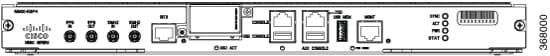
The GPS front panel connector details are:

  • ToD—RS422 format as input

  • 1PPS—1.0/2.3 DIN connector as input

  • 10MHz—1.0/2.3 DIN connector as input

GPS input starts only when all the three signals – 1PPS, 10MHz, and ToD are UP.


Note


Unlike the Ethernet interface, the Sync-2 interface cannot receive or transmit QL. Ensure that you assign a QL value to the Sync-2 interface.


By default, 1PPS and 10MHz are in output mode. ToD output mode is not configurable.

Figure 1. 1PPS, 10MHz, and ToD Ports on the N560-RSP4 Front Panel
This image shows the front panel of the N560-RSP4 that shows the 1PPS , 10MHz, and ToD ports for this router.

Configuring GPS Settings for the Grandmaster Clock

RP/0/RP0/CPU0:router# configure
RP/0/RP0/CPU0:router(config)# clock-interface sync 2 location 0/RP0/CPU0 
RP/0/RP0/CPU0:router(config-clock-if)# port-parameters 
RP/0/RP0/CPU0:router(config-clk-parms)# gps-input tod-format cisco pps-input ttl 
RP/0/RP0/CPU0:router(config-clk-parms)# exit 
RP/0/RP0/CPU0:router(config-clock-if)# frequency synchronization 
RP/0/RP0/CPU0:router(config-clk-freqsync)# selection input 
RP/0/RP0/CPU0:router(config-clk-freqsync)# wait-to-restore 0
RP/0/RP0/CPU0:router(config-clk-freqsync)# quality receive exact itu-t option 1 PRC 
RP/0/RP0/CPU0:router(config-clk-freqsync)# exit 
RP/0/RP0/CPU0:router(config-clock-if)# frequency synchronization 
RP/0/RP0/CPU0:router(config-clk-freqsync)# quality itu-t option 1 
RP/0/RP0/CPU0:router(config-clk-freqsync)# clock-interface timing-mode system 
RP/0/RP0/CPU0:router(config-clk-freqsync)# end
or
RP/0/RP0/CPU0:router(config-clk-freqsync)# commit

Verifying the GPS Input

RP/0/RP0/CPU0:R1# show controllers timing controller clock

SYNCC Clock-Setting: -1 -1 6 -1
		Port 0 	Port 1 	Port 2 	Port 3
Config :      No 	    No 	    Yes 	   No
Mode : 	- 	     - 	     GPS 	   -
Submode1 :    - 	     - 	     CISCO 	 -
Submode2 :    - 	     - 	     UTC 	   -
Submode3 :    0 	     0 	     0 	     0   
Shutdown :    0 	     0 	     0 	     0
Direction :   RX/TX 	 RX/TX 	 RX 	    RX/TX
Baud-Rate :   - 	     - 	     9600 	  -
QL Option :   O1 	    O1 	    - 	     -
RX_ssm(raw):  - 	     - 	     - 	     -
TX_ssm :      - 	     - 	     - 	     -
If_state :    DOWN 	  DOWN 	  UP 	    DOWN  << Port 2 is UP when GPS input is valid.

RP/0/RP0/CPU0:R1# 

When the front panel timing LED is Green, it indicates that the GPS is configured and 1PPS, ToD, and 10M inputs are valid.

Timing LED Behavior:

  • Timing LED is off: Indicates that no GPS is configured or the GPS port is down.

  • Timing LED is green: Indicates that the GPS port is up.

SYNC LED Behavior:

  • SYNC LED is applicable: Only when the timing configuration is applied.

  • SYNC LED is green: Indicates that SyncE is locked.

  • SYNC LED is amber: Indicates a holdover or free-running state.

  • SYNC LED is off: Indicates that the configuration is removed.

Building Integrated Timing Supply (BITS)

Router supports receiving (Rx) and transmitting (Tx) of frequency via BITS interface. To receive and transmit BITS signals, configuration is done under the clock-interface sync 0 on the route processor (RP).

Prerequisite for BITS

Frequency synchronization must be configured with the required quality level option at the global level.

RP/0/RP0/CPU0:ios#show running-config frequency synchronization 
Wed Aug 21 12:37:32.524 UTC
frequency synchronization
 quality itu-t option 1
!

Note


BITS-In and BITS-Out on the peer nodes must be configured with the same mode and format.


Configuring BITS-IN

RP/0/RP0/CPU0:ios#configure 
Wed Aug 21 12:29:59.162 UTC
RP/0/RP0/CPU0:ios(config)#clock-interface sync 0 location 0/RP0/CPU0 
RP/0/RP0/CPU0:ios(config-clock-if)#port-parameters 
RP/0/RP0/CPU0:ios(config-clk-parms)#bits-input e1 crc-4 sa4 ami 
RP/0/RP0/CPU0:ios(config-clk-parms)#exit
RP/0/RP0/CPU0:ios(config-clock-if)#frequency synchronization 
RP/0/RP0/CPU0:ios(config-clk-freqsync)#selection input   
RP/0/RP0/CPU0:ios(config-clk-freqsync)#wait-to-restore 0
RP/0/RP0/CPU0:ios(config-clk-freqsync)#priority 1
RP/0/RP0/CPU0:ios(config-clk-freqsync)#commit
Wed Aug 21 12:30:53.296 UTC

RP/0/RP0/CPU0:ios#show running-config clock-interface sync 0 location 0/RP0/CPU0
Wed Aug 21 12:31:43.350 UTC
clock-interface sync 0 location 0/RP0/CPU0
 port-parameters
  bits-input e1 crc-4 sa4 ami
 !
 frequency synchronization
  selection input
  priority 1
  wait-to-restore 0
 !
!

Configuring BITS-OUT

RP/0/RP0/CPU0:ios#configure 
Wed Aug 21 12:53:24.189 UTC
RP/0/RP0/CPU0:ios(config)#clock-interface sync 0 location 0/RP0/CPU0 
RP/0/RP0/CPU0:ios(config-clock-if)#port-parameters 
RP/0/RP0/CPU0:ios(config-clk-parms)#bits-output e1 crc-4 sa4 ami 
RP/0/RP0/CPU0:ios(config-clk-parms)#commit
Wed Aug 21 12:53:39.411 UTC

RP/0/RP0/CPU0:ios#show running-config clock-interface sync 0 location 0/RP0/CPU0
Wed Aug 21 12:54:02.853 UTC
clock-interface sync 0 location 0/RP0/CPU0
 port-parameters
  bits-output e1 crc-4 sa4 ami
 !
!

Note


Based on the quality level chosen in global configuration, E1/T1 modes can be changed as required. But in all the cases, both TX and RX side modes and submodes must be the same.

For non-CRC-4/D4 modes, SSM is not present in BITS and manual receive quality level must be configured.


Verifying BITS-IN Configuration

RP/0/RP0/CPU0:ios#show controllers timing controller clock 
Wed Aug 21 12:38:20.394 UTC

SYNCC Clock-Setting: 1 -1 -1 -1

          Port 0          Port 1          Port 2          Port 3
Config     : Yes            No             No             No             
Mode       : E1             -              -              -              
Submode1   : CRC-4          -              -              -              
Submode2   : AMI            -              -              -              
Submode3   : 0              0              0              0              
Shutdown   : 0              0              0              0              
Direction  : RX             RX/TX          RX/TX          RX/TX          
Baud-Rate  : -              -              -              -              
QL Option  : O1             O1             -              -              
RX_ssm(raw): 99             -              -              -              
TX_ssm     : -              -              -              -              
If_state   : UP           DOWN           DOWN           DOWN  

Verifying BITS-OUT Configuration

RP/0/RP0/CPU0:ios#show controllers timing controller clock 
Wed Aug 21 12:49:32.923 UTC
SYNCC Clock-Setting: 1 -1 -1 -1

          Port 0          Port 1          Port 2          Port 3
Config     : Yes            No             No             No             
Mode       : E1             -              -              -              
Submode1   : CRC-4          -              -              -              
Submode2   : AMI            -              -              -              
Submode3   : 0              0              0              0              
Shutdown   : 0              0              0              0              
Direction  : TX             RX/TX          RX/TX          RX/TX          
Baud-Rate  : -              -              -              -              
QL Option  : O1             O1             -              -              
RX_ssm(raw): -              -              -              -              
TX_ssm     : 22             -              -              -              
If_state   : UP             DOWN           DOWN           DOWN   

Verify Quality Level Received and Clock Interfaces

RP/0/RP0/CPU0:ios#show frequency synchronization clock-interfaces brief 
Sat Mar 16 07:35:08.351 UTC
Flags:  > - Up                D - Down              S - Assigned for selection
        d - SSM Disabled      s - Output squelched  L - Looped back
Node 0/RP0/CPU0:
==============
  Fl    Clock Interface     QLrcv  QLuse  Pri QLsnd  Output driven by
  ===== =================== ====== ====== === ====== ========================
  >S    Sync0               PRS    PRS      5 n/a    n/a                     
  D     Sync1               n/a    n/a    n/a n/a    n/a                     
  D     Sync2               n/a    n/a    n/a n/a    n/a                     
  >S    Internal0           n/a    ST3    255 n/a    n/a