Cisco Evolved Programmable Network Manager 2.1.1 User and Administrator Guide
Bias-Free Language
The documentation set for this product strives to use bias-free language. For the purposes of this documentation set, bias-free is defined as language that does not imply discrimination based on age, disability, gender, racial identity, ethnic identity, sexual orientation, socioeconomic status, and intersectionality. Exceptions may be present in the documentation due to language that is hardcoded in the user interfaces of the product software, language used based on RFP documentation, or language that is used by a referenced third-party product. Learn more about how Cisco is using Inclusive Language.
- Updated:
- June 1, 2017
Chapter: Configure Devices
- Ways to Configure Devices Using Cisco Evolved Programmable Network Manager
- Which Devices Support the Configuration Operations?
- Identify the Commands Used In a CLI Configuration Template
- Save Your Device Changes
- Change a Device's Credentials and Protocol Settings
- Change Basic Device Properties
- Enable and Disable Interfaces
- Configure Circuit Emulation
- Configure Alarm Profiles on Ports, Cards, and Nodes of Devices
- Synchronize the Clock Using Sync-E, BITS, and PTP
- Configure IP SLAs (TWAMP Responder)
- Configure Interfaces
- Configure Ethernet Interfaces and Subinterfaces
- Configure Loopback Interfaces
- Configure Tunnel Interfaces
- Configure SwitchPort Interfaces
- Configure Virtual Template Interfaces
- Configure VLAN Interfaces
- Configure Optical Interfaces
- Configure Cards from the Chassis View
- Delete a Card
- Reset a Card
- Configure cards: OTU2-XP, MR-MXP, WSE, AR-XPE, AR-XP, AR-MXP, 40E-MXP-C, and 40ME-MXP-C
- Configure cards: 400G-XP, 100G-CK-C, 100ME-CK-C, 200G-CK-LC, 100GS-CK-C, 100G-LC-C, 100G-ME-C, and 10x10G-LC
- Configure SONET and Flex Line Cards
- Edit and Delete Pluggable Port Modules and Card Mode Configuration
- Cards and Supported Configuration for Cisco NCS 2000 Devices
Configure
Devices
This chapter provides the following topics:
- Ways to Configure Devices Using Cisco Evolved Programmable Network Manager
- Which Devices Support the Configuration Operations?
- Identify the Commands Used In a CLI Configuration Template
- Save Your Device Changes
- Change a Device's Credentials and Protocol Settings
- Change Basic Device Properties
- Enable and Disable Interfaces
- Configure Circuit Emulation
- Configure Alarm Profiles on Ports, Cards, and Nodes of Devices
- Synchronize the Clock Using Sync-E, BITS, and PTP
- Configure IP SLAs (TWAMP Responder)
- Configure Interfaces
- Configure Devices Using the Chassis View
- Configure Optical Cards
- Discover and Configure MPLS LDP and MPLS-TE Links
- Analyze Ports Using SPAN and RSPAN
- Configure and View Ethernet Link Aggregation Groups
- Configure Routing Protocols and Security
- Configure EOAM Fault and Performance Monitoring
- Configure Quality of Service (QoS)
- Launch Cisco Transport Controller to Manage Cisco NCS and Cisco ONS Devices
Ways to Configure Devices Using Cisco Evolved Programmable Network Manager
Cisco EPN Manager provides two ways to change the physical devices in your network. The actions you can perform depend on your user account privileges and the types of devices in your network.
|
Launch Points for Configuring Devices |
Use this method to: |
|---|---|
|
Configuration menu from left-side navigation menu |
Perform common network management tasks on one or more devices using system templates—for example, adding a hostname or configuring a routing protocol. You can also create your own templates to fit your deployment needs. Because they can be applied to multiple devices, templates normally apply to specific device operating systems or device types. When you use a configuration template, Cisco EPN Manager only displays devices that meet the template criteria. |
 Note | You can also edit device properties from the Network Devices table () by choosing a device and clicking Edit. This launches the device Edit Wizard. However, changes you make using the wizard are limited to device credentials, and any changes you make do not affect the physical device; they only update device information that is stored in the database. |
For optical devices, you can also configure devices using Cisco Transport Controller, which you can launch from Cisco EPN Manager . See Launch Cisco Transport Controller to Manage Cisco NCS and Cisco ONS Devices
After you make your changes, save your changes to the database and optionally collect the device's physical and logical inventory. For more information, see Collect a Device's Inventory Now (Sync).
Which Devices Support the Configuration Operations?
Configuration operations are supported on a device if:
-
The device model is supported by Cisco EPN Manager .
-
The device operating system is supported by Cisco EPN Manager .
-
The applicable technology or service is supported by c and is enabled on the device.
To find out what is supported, see Cisco Evolved Programmable Network Manager Supported Devices.
Identify the Commands Used In a CLI Configuration Template
Use this procedure to view the exact commands that are used by any of the commands you launch from the CLI Templates drawer.
Save Your Device Changes
After you make a change to a device, save your changes to the database and, if desired, collect the device's physical and logical inventory. See these topics for more information:
Save Device Configuration Changes to the Database (Update)
After making a change to your devices, you should save those changes to the database by clicking Update in the configuration window. If an Update button is not provided, perform a manual sync which will save your changes, but also collect the device's physical and logical inventory and save it to the database. See Collect a Device's Inventory Now (Sync)
Collect a Device's Inventory Now (Sync)
The Sync operation performs an immediate inventory collection for a device. When it performs a Sync, Cisco EPN Manager collects the selected device's physical and logical inventory and synchronizes the database with any updates. If you do not perform a Sync operation after making a change to a device, your change will not be saved to the database until the daily inventory collection.
Note | The Sync operation is different from the Update operation. Update saves configuration changes without performing an inventory collection. If you want to use Update instead of Sync, see Save Device Configuration Changes to the Database (Update). |
Note | This Sync operation is different from working with out-of-sync device configuration files. An out-of-sync device is a device that has a startup configuration files that is different from its running configuration file. For more information, see Synchronize Running and Startup Device Configurations. |
Use one of these methods perform a manual Sync.
|
To collect the inventory for: |
Do the following: |
|---|---|
|
A single device |
|
|
Multiple devices |
From the Network Devices table, select the devices (by checking their check boxes), then click Sync. |
Change a Device's Credentials and Protocol Settings
Use the following procedure to update device credentials and protocol settings. When you save the settings to the database, you can also perform an inventory collection to gather all physical and logical device changes and save those changes to the database, rather than wait for the daily inventory collection.
Change Basic Device Properties
Cisco EPN Manager provides command templates that you can use to make basic property changes on your physical devices. To use these templates, choose , then choose from the Templates pane on the left.
Note | The operations you perform here are different from those you perform with the Edit wizard (which you can launch from the Network Devices table). The Edit wizard changes the device property information that is saved in the database. It does not change properties on physical devices. |
|
CLI Configuration Template Name |
Use it to: |
Required Input Values |
|---|---|---|
|
Add-Host-Name-IOS and -IOS-XR |
Configure the client host name |
Host name |
|
Remove-Host-Name-IOS and -IOS-XR |
||
|
Syslog-Host-Logging-IOS and -IOS-XR |
Specify host to which messages of a certain level will be logged |
Host name |
|
Add-Tacacs-Server-IOS and -IOS-XR |
Configure the TACACS or TACACS+ server to use for authentication |
Host address, key value, authentication list name, group name |
|
Remove-Tacacs-Server-IOS and -IOS-XR |
||
|
Add-Tacacs-Plus-Server-IOS and -IOS-XR |
||
|
Remove-Tacacs-Plus-Server-IOS and -IOS-XR |
||
|
Add-SNMP-Configuration-IOS and -IOS-XR |
Configure SNMP version, password, password encryption, server and group settings, UDP port, and so forth |
Host name, community name |
|
Remove-SNMP-Configuration-IOS and -IOS-XR |
||
|
Enable-Traps-ASR903 |
Enable and disable traps on the Cisco ASR 903 |
Trap name (a list is provided) |
|
Disable-Traps-ASR903 |
||
|
Enable-Traps-IOS and -IOS-XR |
Enable and disable traps on Cisco IOS and Cisco IOS XR devices |
|
|
Disable-Traps-IOS and -IOS-XR |
||
|
Enable-Traps-ME3600 and -ME3800 |
Enable and disable traps on the Cisco ME3600 and ME3800 |
|
|
Disable-Traps-ME3600 and -ME3800 |
||
|
Enable-Trap-Host-IOS and IOS-XR |
Set a target host for SNMP traps |
Host IP address, community string |
|
Show-Users-on-Device-IOS and -IOS-XR |
Display user session information for Cisco IOS and Cisco IOS XR devices |
(Executed from selected device; no input required) |
Enable and Disable Interfaces
Use the Interface 360 view to quickly enable and disable an interface. While you can perform these same actions from a Device Details page, using the Interface 360 view may be more efficient (for example, when responding to an alarm). The top right of the Interface 360 view provides an Actions menu that provides enable and disable options.
To launch an Interface 360 view, see Get a Quick Look at a Device Interface: Interface 360 View.
To enable and disable an interface from a device's Device Details page, see the interface configuration topics (Ethernet, Loopback, Tunnel, and so forth).
Configure Circuit Emulation
Cisco EPN Manager supports the provisioning of Circuit Emulation (CEM) which provides a bridge between traditional TDM network and packet switched network (PSN). CEM is a way to carry TDM (or PDH) circuits over packet switched network. Circuit Emulation (CEM) is the imitation of a physical connection. This feature allows you to use your existing IP network to provide leased-line emulation services or to carry data streams or protocols that do not meet the format requirements of other multiservice platform interfaces.
Cisco EPN Manager supports the following CEM modes:
-
Structure-Agnostic time-division multiplexing (TDM) over Packet (SAToP)—This is the unstructured mode in which the incoming TDM data is considered as an arbitrary bit stream. It disregards any structure that may be imposed on the bit stream. SAToP encapsulates the TDM bit streams as pseudowire (PWs) over PSN.
-
Circuit Emulation over Packet (CEP)—This mode is used to emulate Synchronous Optical Network/Synchronous Digital Hierarchy (SONET/SDH) circuits and services over MPLS. To transport SONET/SDH circuits through a packet-oriented network, the Synchronous Payload Envelope (SPE) or Virtual Tributary ( VT) is broken into fragments. A CEP header and optionally an RTP header are prepended to each fragment.
For more information about CEM in Cisco EPN Manager , see, Supported Circuit Emulation Services.
When a line is channelized, it is logically divided into smaller bandwidth channels called higher-order paths (HOP) and lower-order paths (LOP). These paths carry the SONET payload. When a line is not channelized, the full bandwidth of the line is dedicated to a single channel that carries broadband services. Cisco EPN Manager enables you to channelize the T3 or E3 channels into T1s, and channelize the T1s further into DS0 time slots. Before you provision CEM services using Cisco EPN Manager, you must first configure the parameters for the HOP and LOP by configuring the interfaces for CEM.
A channelized SONET interface is a composite of STS streams, which are maintained as independent frames with unique payload pointers. The frames are multiplexed before transmission. SONET uses Synchronous Transport Signal (STS) framing while SDH uses Synchronous Transport Mode (STM) framing. An STS is the electrical equivalent to an optical carrier 1 (OC-1) and an STM-1 is the electrical equivalent to 3 optical carrier 1s (OC-1s).
This section describes how you can use Cisco EPN Manager to first configure your interfaces for CEM. You can then provision CEM services using these interfaces configured with appropriate controller modes and protection groups.
- Pre-requisites for Configuring CEM Services
- Configure Interfaces for CEM
- View Protection Groups
- Configure Clocking for CEM
- CEM Interface (PDH, SONET, and SDH) Field Descriptions
Pre-requisites for Configuring CEM Services
Before you provision a CEM service (see Provision Circuit Emulation Services), ensure that the following pre-requisites are met:
-
Configure the required loopback settings for CEM on the device. See, Configure Loopback Interfaces.
-
Configure the required CEM parameters on SONET, SDH, PDH, HOP, and HOP controllers. See, Configure Interfaces for CEM.
-
Configure the working and backup interface groups to provide APS protection. See, View Protection Groups.
Configure Interfaces for CEM
Using Cisco EPN Manager , you can configure your interfaces with Circuit Emulation (CEM). To do this, you must first set appropriate controller modes on your interfaces and then configure the PDH (E1, T1, E3, T3) , SONET, and SDH controllers for CEM. After you configure the interfaces with CEM, you can then use the interfaces for provisioning CEM services. See Provision Circuit Emulation Services.
To configure the interfaces for CEM:
|
CEM Interface Configuration |
Navigation |
Comments/Descriptions |
Supported Slots/Controllers |
||
|---|---|---|---|---|---|
|
Configure controller modes as SONET, SHD, Ethernet, T3, or E3. |
|
– |
– |
||
|
Configure card modes as 5G or 10G. |
|
You can change the configuration from 10G to 5G but the other way around is not supported. Depending on the device you select, the default card mode is set to either 5G or 10G. For mode detailed information on the supported card modes, see Supported Devices for Cisco EPN Manager
|
For more information about the device slots and supported card mode types, see table below (Device Slots and Supported Card Mode Types). |
||
|
Configure PDH (E1, T1, E3, and T3) controllers |
|
For a description of the different PDH parameters, see CEM Interface (PDH, SONET, and SDH) Field Descriptions |
|
||
|
Configure SONET and SDH controllers for CEM |
|
For a description of the different SONET and SDH parameters, see CEM Interface (PDH, SONET, and SDH) Field Descriptions |
For more information about the device ports and supported controller types, see table below (Controller Modes and Supported Port Types). |
||
|
Configure a working and protecting member interface for CEM provisioning. |
|
|
|||
|
Configure the interface module type for Automatic In-Service (AINS) |
|
Use this menu to configure the right controller types for AINS. In case of manual insertion and removal of cards, the AINS values are populated after a 20 min delay. |
|
||
|
Configure the interface pluggable type for virtual Container over Packet (VCoP). |
|
Use this menu to select the right port types for VCoP enabled interfaces. For example, the port types can be OC3, OC12, or DS3.
|
|
|
Cisco NCS 4206 Devices |
Cisco NCS 4216 Devices |
Cisco ASR903 Devices |
Cisco ASR907 Devices |
|---|---|---|---|
|
|
|
|
|
|
Ethernet (0-7) |
SONET (0-3) |
SONET (4-7) |
|---|---|---|
|
|
|
|
CEM Interface Configuration Example:
The following example show the sample CEM interface configuration that is deployed to the device for CEM framing type 'unframed', c-11 mode, clock source of type 'internet', and ACR values associated with the Protection Group 'acr 255':
NCS4206-120.32#show running-config | section 0/4/0
controller MediaType 0/4/0
 mode sonet
controller SONET 0/4/0
 rate OC3
 no ais-shut
 framing sonet
 clock source line
 loopback network
 !
 sts-1 1
  clock source internal
  mode unframed
  cem-group 1 cep
 !
 sts-1 2
  clock source internal
  loopback network
  mode unframed
  cem-group 2 cep
 !
 sts-1 3
  clock source internal
  mode vt-15
  vtg 1 vt 1 protection-group 15 working
  vtg 1 vt 3 protection-group 16 working
  vtg 1 vt 4 protection-group 17 working
 !
 aps group acr 255
 aps protect 1 6.6.6.6 / aps working 1
!
interface CEM0/4/0
 no ip address
 cem 1
 !
 cem 2
 !
connect sam CEM0/4/0 1 CEM0/4/0 2
 !
NCS4206-120.32#
View Protection Groups
Configuring protection groups for CEM helps you enable Automatic Protection Switching (APS) for your devices. APS refers to the mechanism of using a protect interface in the SONET network as the backup for the working interface. Associating your CEM interfaces with APS or protection groups, ensures that when the working interface fails, the protect interface quickly assumes its traffic load. The working interfaces and their protect interfaces together make up a Protection Group. SONET Protection Groups offer recovery from fiber (external) or equipment (interface and internal) failures at the SONET line layer. Using Cisco EPN Manager , you can view the working member for a SONET controller which acts as the main functioning controller for the CEM circuit. The Protecting Member acts as a backup for the main working controller. To view these details, ensure that the interfaces have been set with the required controller modes as explained in Configure Interfaces for CEM.
To view Protection Groups for your CEM interfaces:
Configure Clocking for CEM
Clocking modes define multiple ways to achieve the same clock in the transmitting and receiving ends of a CEM circuit. Cisco EPN Manager enables you to configure clock recovery and distribution in these ways:
- Synchronous Clocking — with
synchronous clocking, PDH (TDM) lines on the source and destination are
synchronized to the same clock delivered by some means of physical clock
distribution (SONET, SDH, and so on). The clock on the particular TDM line can
be delivered from
-
Line: the transmit clock is from the receiver of the same physical line.
-
Internal: the controller will clock its sent data using the internal clock.
-
Free Running: the transmit clock is taken from line card and can be derived from an internal free running oscillator.
-
Recovered: the transmit clock is derived from an in-band pseudowire-based activeclock recovery on a CEM interface.
To set these clocking values in Cisco EPN Manager , see Configure CEM Interfaces.
-
-
Adaptive Clocking — adaptive clocking is used when the routers do not have a common clock source. The clock is derived based on packet arrival rates based on dejitter buffer fill level. You can set the size of the Dejitter Buffer (in the range of 1-32) during provisioning of CEM services in Cisco EPN Manager . The size of the Dejitter Buffer determines the ability of the circuit to tolerate network jitter.
-
Differential clocking — differential clocking is used when the cell site and aggregation routers have a common clock source but the TDM lines are clocked by a different source. The TDM clocks are derived from differential information in the RTP header of the packet with respect to the common clock. Differential clock recovery is based on time stamps received in the RTP header.
To configure clock recovery for CEM:
CEM Interface (PDH, SONET, and SDH) Field Descriptions
To configure the CEM parameters listed in the table below:
| Step 1 | Configure the required CEM parameters on SONET, PDH, HOP, and HOP controllers. See, Configure Interfaces for CEM. |
| Step 2 | Configure
clock distribution and recovery for CEM. See
Configure Clocking for CEM.
|
Configure Alarm Profiles on Ports, Cards, and Nodes of Devices
The Alarm Profiles feature allows you to change default alarm severities by creating unique alarm profiles for different interfaces of the device. An Alarm Profile applied to one node on the network cannot be applied to other nodes using Cisco EPN Manager . When you create Alarm Profiles, they are first stored on the node before they can be applied to the node, card, or port (using the Alarm Behavior menu). The Alarm Behavior menu displays the alarm profiles saved on the selected device.
In the Node view, the Alarm Behavior tab displays the alarm profiles for the node. Alarms form a hierarchy. A node-level alarm profile applies to all cards in the node, except those that have their own profiles. A card-level alarm profile applies to all ports on the card, except those that have their own profiles. At the node level, apply profile changes on a card-by-card basis or set a profile for the entire node. At the card level, apply profile changes on a port-by-port (module) basis or set the profiles for all ports on that card simultaneously (using the Port Profiles tab).
Note | If an Alarm Profile is applied to a node, it cannot be applied to the cards and ports associate with the same node. And if it is applied to the card, it cannot be applied to the ports associate with the same card. |
To create alarm profiles and associate them with interfaces:
Synchronize the Clock Using Sync-E, BITS, and PTP
Synchronous Ethernet (Sync-E):
Using Cisco EPN Manager , you can enable frequency synchronization to provide high-quality bit clocks synchronization over Ethernet interfaces. Synchronous Ethernet (Sync-E) provides this required synchronization at the physical level.
Note | Sync-E configuration is supported only on Ethernet interfaces. |
Building Integrated Timing Supply (BITS):
BITS is the method by which clocking information is provided by a Building Integrated Timing Supply (BITS) port clock. In Sync-E, Ethernet links are synchronized by timing their bit clocks from high-quality, stratum-1-traceable clock signals in the same manner as SONET/SDH. Operations messages like SSM and ESMC maintain Sync-E links and ensure that a node always derives its timing from the most reliable source.
Precision Time Protocol (PTP):
In networks that employ TDM, periodic synchronization of device clocks is required to ensure that the receiving device knows which channel is the right channel for accurate reassembly of the data stream. The Precision Time Protocol (PTP) standard:
-
Specifies a clock synchronization protocol that enables this synchronization.
-
Applies to distributed systems that consist of one or more nodes communicating over a network.
PTP uses the concept of master and slave devices to achieve precise clock synchronization. With the help of Cisco EPN Manager , you can use PTP to configure the master device which periodically starts a message exchange with the slave devices. After noting the times at which the messages are sent and received, each slave device calculates the difference between its system time and the system time of the master device. The slave device then adjusts its clock so that it is synchronized with the master device. When the master device initiates the next message exchange, the slave device again calculates the difference and adjusts its clock. This repetitive synchronization ensures that device clocks are coordinated and that data stream reassembly is accurate. The PTP clock port commands are used to modify PTP on individual interfaces. Once the PTP properties have been configured, you can view the logical hierarchy and topology between the devices on the network topology overlay.
Note | Due to the limitations on the device, you can configure a maximum of 4 clock sources on interface modules, with a maximum of 2 per interface module. This limitation applies to both Sync-E and TDM interfaces. |
To configure Sync-E, BITS, and PTP:
What to Do Next
(Optional) You can view the Sync-E and PTP device properties on the network topology overlay. See Show Clock Synchronization Networks on a Network Topology Map:
-
Sync-E overlay: shows the topology and hierarchy of the Sync-E network. It shows the primary clock and the primary and secondary clock inputs for each device.
-
PTP overlay: shows the clock synchronization tree topology, the hierarchy of the Precision Time Protocol, and the clock role of each device in the tree (master, boundary, slave, or transparent).
Configure IP SLAs (TWAMP Responder)
The IETF Two-Way Active Measurement Protocol (TWAMP) defines a standard for measuring round-trip IP performance between any two devices that support the TWAMP protocols. The TWAMP-Control protocol is used to set up performance measurement sessions. It is used to send and receive performance-measurement probes. TWAMP enables complete IP performance measurement and provides a flexible choice of solutions as it supports all devices deployed in a network.
When you configure TWAMP using Cisco EPN Manager , the device you select is configured as a TWAMP server and you enter the TWAMP server configuration mode. It then uses the port value that you specify to configure the port to be used by the TWAMP server that listens for connection and control requests. The Inactivity Value that you specify will be configured as the inactivity timer (in seconds) for a TWAMP control session.
Note | When you configure IP SLA using Cisco EPN Manager , the IP SLA responder is automatically configured on the device. You do not have to use the command ip sla responder twamp to pre-configure the IP SLA responder. |
To configure interfaces for TWAMP:
A TWAMP control-client and the session-sender must be pre-configured in your network before you can configure TWAMP responder using Cisco EPN Manager .
For IP SLAs TWAMP Responder v1.0, ensure that the TWAMP server and the session-reflector are configured on the same Cisco device.
| Step 1 | Choose Configuration > Network Devices. |
| Step 2 | Select the device that you want to configure by clicking the device hyperlink to launch its Device Details page. |
| Step 3 | Click the Configuration tab, then click the Logical View left side tab. |
| Step 4 | Choose IP SLA > TWAMP Responder to add or edit the TWAMP Responder configuration. |
| Step 5 | Click the '+' icon to add the TWAMP parameters to the selected device. To edit existing parameters, click the Port Name hyperlink and click the Edit icon at the top right corner of the page. You can only add one set of TWAMP parameters per device. |
| Step 6 | Make your
modifications to the following parameters. All parameters are mandatory.
|
| Step 7 | Click
Save
to deploy your changes to the device.
If the deploy fails, ensure that the device's Inventory Collection status is 'Completed'. You also need to ensure that the pre-requisites mentioned above are met. |
Configure Interfaces
Using Cisco EPN Manager , you can configure your CE and Optical Interfaces using the following configuration options:
Before you configure the interfaces, ensure that the device's Inventory Collection status is 'Completed'.
- Configure Ethernet Interfaces and Subinterfaces
- Configure Loopback Interfaces
- Configure Tunnel Interfaces
- Configure SwitchPort Interfaces
- Configure Virtual Template Interfaces
- Configure VLAN Interfaces
- Configure Optical Interfaces
Configure Ethernet Interfaces and Subinterfaces
The Configuration tab on the Device Details page lists the current interface configurations on the device. Depending on your device configuration and user account privileges, you can create, edit, delete, enable, and disable these interfaces.
| Step 1 | Choose Configuration > Network Devices. | ||
| Step 2 | Click the device hyperlink to launch its Device Details page. | ||
| Step 3 | Click the Configuration tab, then click the Logical View left side tab. | ||
| Step 4 | Choose Interfaces > Ethernet. | ||
| Step 5 | To add an
Ethernet subinterface:
| ||
| Step 6 | To enable,
disable, or delete interfaces and subinterfaces, select the interfaces and
click the appropriate buttons.
The Delete Subinterface button may only be enabled on some supported devices, such as, Cisco ASR903 devices. | ||
| Step 7 | Click Save to deploy your changes to the device. |
Configure Loopback Interfaces
You can change the loopback state of an interface to test how your optical network is performing. Before changing the loopback setting, ensure that the device is either in Managed state or ideally in Complete state.
To change the loopback settings on an interface:
| Step 1 | Choose Configuration > Network Devices. |
| Step 2 | Select the device that you want to configure by clicking the device hyperlink to launch its Device Details page. |
| Step 3 | Click the Configuration tab, then click the Logical View left side tab. |
| Step 4 | Choose Interfaces > Loopback. |
| Step 5 | To specify a
new loopback interface, click
Add.
|
| Step 6 | To edit an existing loopback interface, select the interface and click the Edit button to change only the speed, duplex, and other settings. The Interface Number cannot be edited. |
| Step 7 | To enable the above loopback settings on the interfaces, select the required loopback process and click Enable. |
| Step 8 | Click Save to deploy these configuration changes on the device. |
Configure Tunnel Interfaces
The Configuration tab in the Device Details page lists the current interface configurations on the device. Depending on your device configuration and user account privileges, you can create, edit, delete, enable, and disable these interfaces.
| Step 1 | Choose Configuration > Network Devices. |
| Step 2 | Click the device hyperlink to launch its Device Details page. |
| Step 3 | Click the Configuration tab, then click the Logical View left side tab. |
| Step 4 | Choose Interfaces > Tunnel. |
| Step 5 | To create a new
tunnel interface, click
Add.
|
| Step 6 | To edit an existing tunnel interface, you can change the speed, duplex setting, and other parameters listed in the previous step except the Interface Number parameter. |
| Step 7 | To enable, disable, or delete a tunnel interface, select the interfaces and click the appropriate buttons. |
| Step 8 | Click Save. |
Configure SwitchPort Interfaces
The Configuration tab in the Device Details page lists the current interface configurations on the device. Depending on your device configuration and user account privileges, you can create, edit, delete, enable, and disable these interfaces.
| Step 1 | Choose Configuration > Network Devices. |
| Step 2 | Click the device hyperlink to launch its Device Details page. |
| Step 3 | Click the Configuration tab, then click the Logical View left side tab. |
| Step 4 | Choose Interfaces > SwitchPort. |
| Step 5 | To edit an interface, select the interface and click Edit. |
| Step 6 | Click Save. |
Configure Virtual Template Interfaces
The Configuration tab in the Device Details page lists the current interface configurations on the device. Depending on your device configuration and user account privileges, you can create, edit, delete, enable, and disable these interfaces.
| Step 1 | Choose Configuration > Network Devices. |
| Step 2 | Click the device hyperlink to launch its Device Details page. |
| Step 3 | Click the Configuration tab, then click the Logical View left side tab. |
| Step 4 | Choose Interfaces > Virtual Template. |
| Step 5 | To create a new
virtual template interface, click
Add.
|
| Step 6 | To edit an existing tunnel interface, you can change the speed, duplex setting, and other parameters listed in the previous step except the Interface Number parameter. |
| Step 7 | To enable, disable, or delete a tunnel interface, select the interfaces and click the appropriate buttons. |
| Step 8 | Click Save. |
Configure VLAN Interfaces
The Configuration tab in the Device Details page lists the current interface configurations on the device. Depending on your device configuration and user account privileges, you can create, edit, delete, enable, and disable these interfaces.
Configure Optical Interfaces
Using EPN Manager you can configure your optical interfaces to change their admin settings, enable standard FEC modes on them, modify their payload settings, and change their loopback settings. To do this, use the Configuration tab in the Device Details page which lists the current interface configurations on the device. Depending on your device configuration and user account privileges, you can create, edit, delete, enable, and disable these interfaces.
You can configure optical interfaces in the following ways:
- Change the Loopback Settings on an Optical Interface
- Continuous Verification of the Connection Status
- Configure PRBS on ODU Controllers
- Enable and Disable OSC
- View and Acknowledge Unverified Alarms
- Provision Optical Interfaces
- Example: Change the Admin Status for Cisco NCS 2006 Interface
Change the Loopback Settings on an Optical Interface
You can change the loopback state of an interface to test how your optical network is performing. Before changing the loopback setting, ensure that the device is either in Managed state or ideally in Complete state. The interface that you want to modify must be in Maintenance (OOS, MT) admin state. EPN Manager allows you to edit the loopback settings only on SONET, SDH, Ethernet, FC/FICON, and OTN interface types.
To change the loopback settings on an interface:
| Step 1 | Choose . | ||
| Step 2 | Click the device hyperlink to launch its Device Details page. | ||
| Step 3 | Click the Configuration tab. For Cisco NCS 2000 and Cisco ONS devices, this choice is under the Logical View tab that is at the top of the Device Details page. | ||
| Step 4 | Choose . The interfaces of the selected device are displayed along with their loopback settings. Interfaces that are not supported, for example, Data Storage, OTS, or Video, are not displayed. | ||
| Step 5 | To edit the
loopback settings, select the interface name (hyperlink) and click
Edit to make
your changes. Ensure that the device is in Managed or Complete state and the
interface is in Maintenance (OOS, MT) admin state.
Before you change the loopback state ensure that you first clear the current loopback setting using the No_loopback option from the drop-down menu and then re-apply the setting of your choice. | ||
| Step 6 | Click
Save to save
your edits.
A pop-up notification notifies you about the status of your changes.
|
Continuous Verification of the Connection Status
Using the Connection Verification feature, you can view the power levels of optical interfaces and verify the interfaces for connectivity and insertion loss. Verifying the connectivity indicates whether the cable is in a connected state and verifying the insertion loss indicates whether the cable loss is within an expected value. The parameters for insertion losses are collected for every possible optical path inside the network element in order to predict possible failures.
Using Cisco EPN Manager you can view the Connection Verification parameters and opt to enable or disable Connection Verification on interfaces. You can also set the acknowledgment values for associated alarms.
To verify the connection status for your optical interfaces:
| Step 1 | Choose Configuration > Network Devices. |
| Step 2 | Click the device hyperlink to launch its Device Details page. |
| Step 3 | Click the Configuration tab. For Cisco NCS 2000 and Cisco ONS devices, this choice is under the Logical View tab that is at the top of the Device Details page. |
| Step 4 | To enable or disable the Connection Verification feature and set the common threshold vales, click Optical Interfaces > Provisioning > Connection Verification. |
| Step 5 | Click the Edit icon at the top right corner of the page to edit common parameters. |
| Step 6 | Enter the
following threshold parameters for the selected device and click
Save:
|
| Step 7 | Click
Optical
Interfaces > Maintenance > Connection Verification Entry.
For Cisco NCS 2000 and Cisco ONS devices, this choice is under the Logical View tab that is at the top of the Device Details page. |
| Step 8 | Click the A Side
hyperlink to view the following values of the connection:
|
| Step 9 | In the Connection Verification Action drop-down menu, choose an action that must be taken when the configured threshold values are reached, and click Save. Your options are: Verify loss and connectivity, Disable verification, and Acknowledge loss alarm. |
| Step 10 | (Optional)
Select one of the following values to specify how alarms must be generated with
respect to the Connection Verification parameters:
|
Configure PRBS on ODU Controllers
Pseudo Random Binary Sequence (PRBS) is a testing mechanism used to ensure that the selected overhead bytes can be used to transport the header and trailer data safely. Both the transmitting node and receiving node must be aware that PRBS testing is taking place. To do this you can use Cisco EPN Manager to enable appropriate PRBS modes on the nodes. Cisco EPN Manager allows you to configure PRBS only on the non-channelized ODU controllers of an optical device.
PRBS also enables trunk ports to generate the PRBS_31 pattern and detect PRBS_11, PRBS_23, and PRBS_31 patterns.
| Step 1 | Choose Configuration > Network Devices. |
| Step 2 | Click the device hyperlink to launch its Device Details page. |
| Step 3 | Click the Configuration tab. For Cisco NCS 2000 and Cisco ONS devices, this choice is under the Logical View tab that is at the top of the Device Details page. |
| Step 4 | Choose Optical Interfaces > Maintenance > PRBS Configuration. All ODU controllers and their current PRBS parameters are displayed. If the controllers are not listed, ensure that the above stated pre-requisites are met. |
| Step 5 | To configure PRBS, click the controller’s name hyperlink and click the Edit icon at the top right corner of the page. |
| Step 6 | Make your
modifications to the following parameters.
|
| Step 7 | Click Save to deploy the updated configuration to the device. |
| Step 8 | (Optional) To verify, view updated PRBS parameters in the Configuration tab for the selected controller, under Optical Interfaces > Provisioning > PRBS. To run a PRBS test on ODU UNI circuits, see, Run PRBS Test on Circuits (ODU UNI). |
Enable and Disable OSC
Using Cisco EPN Manager, you enable or disable the Optical Service Channel (OSC) terminations on the interfaces of optical devices. OSC can be configured on OC3 lines, and on FastEthernet (FSTE) and GigabitEthernet (GigE) interfaces of the following cards:
-
Transmission Network Control System (TNCS)
-
Transport Node Controller - Enhanced (TNCE)
-
Transport Node Controller (TNC)
For ONS15454 NEs, the supported interfaces are OC3 interfaces of the following cards:
-
Optical Service Channel Modem (OSCM)
-
Optical Service Channel and Combiner/Separator Module (OSC-CSM)
To configure OSC on optical devices:
| Step 1 | Choose Configuration > Network Devices. |
| Step 2 | Click the device hyperlink to launch its Device Details page. |
| Step 3 | Click the Configuration tab. For Cisco NCS 2000 and Cisco ONS devices, this choice is under the Logical View tab that is at the top of the Device Details page. |
| Step 4 | Choose
Optical
Interfaces > Comm Channels.
All configurable G709 enabled interfaces of the selected device are displayed. |
| Step 5 | Click the OSC tab. |
| Step 6 | Choose the
communication channel that that you want to configure by clicking the
communication channel’s name hyperlink.
The communication channel name and current OSC setting is displayed. |
| Step 7 | Click the Edit icon at the top right of the page. |
| Step 8 | Use the OSC checkbox to enable or disable OSC on the selected communication channel. |
| Step 9 | Click
Save.
Your changes are saved and the updated configuration is deployed to the device. To verify, view the OSC settings for the selected communication channel under Optical Interfaces > Provisioning > Comm Channels. |
View and Acknowledge Unverified Alarms
Based on the alarm generated on your devices, you can view the details of the alarm in Unverified status and then mark them Acknowledged so that they no longer appear as unread alarm notifications on the device. To do this:
| Step 1 | Choose Configuration > Network Devices. |
| Step 2 | Click the device hyperlink to launch its Device Details page. |
| Step 3 | Click the Configuration tab. For Cisco NCS 2000 and Cisco ONS devices, this choice is under the Logical View tab that is at the top of the Device Details page. |
| Step 4 | Choose to view the alarms with the Unverified status. |
| Step 5 | Once you have reviewed the alarms and taken the required action, select the alarms and click the Acknowledge button to mark these alarms Verified directly on the device. |
Provision Optical Interfaces
You can use Cisco EPN Manager to enable the following configuration options on your optical devices.
Note | The following configuration options are enabled or disabled depending on the device you select. To check whether your device supports these options, see Supported Devices for Cisco EPN Manager. |
- Ethernet MTU
Using Cisco EPN Manager you can configure the MTU values on the Ethernet interfaces of your optical devices. The MTU is the Maximum Transmission Size, in bytes, of a packet passing through the interface. You can use Cisco EPN Manager to modify the MTU values on all Ethernet interfaces except Gigabit Ethernet and Fast Ethernet interfaces on TNC and ECU modules.
To verify that your new Ethernet MTU values are configured on the device, navigate to your device’s Device Details page and click the Ethernet Interface tab.
-
GMPLS
Using Generalized Multi-Protocol Label Switching (GMPLS), you can define and view the fiber and alien wavelength parameters that are used during GMPLS circuit creation. It ranges the packet based data on the MPLS protocol to allow the creation and maintenance of channels across the networks. It supports non-packet switching devices. This means that GMPLS extends the packet based MPLS protocol to allow creation and maintenance of tunnels across networks that consist of non-packet switching devices. GMPLS tunnels can traverse Time-Division Multiplex (TDM) interfaces and switching types.
To configure GMPLS, you can use the Configuration tab in Cisco EPN Manager which allows you to configure GMPLS on all LMP enabled optical controllers. The enabling of LMP which is a pre-requisite for GMPLS configuration can also be done using the same Configuration tab.
Note
You cannot disable GMPLs on LMP enabled controllers that are part of active optical circuits.
- Packet Termination
Using Cisco EPN Manager you can set up packet termination on the ODU controllers of your optical devices. To do this, ensure that packet termination is pre-configured on the device for Ethernet packets. You can then edit the configuration that is already created on the device and discovered by Cisco EPN Manager .
To configure packet termination, you must specify both the Termination Mode and Mapping Mode values.
- LMP
The Link Management Protocol (LMP) helps in managing channels and links that are required between nodes for routing, signaling, and link management. LMP is also used to manage the Traffic Engineering (TE) link. It allows multiple data links into a single Traffic Engineering (TE) link that runs between a pair of nodes.
To create an LMP neighbor using Cisco EPN Manager , you need to specify the neighbor’s name, link ID, router ID, and interface ID, and the common link and interface IDs. You can add only one LMP link per controller on your optical device.
While the LMP configuration can be successfully deployed to a single device using Cisco EPN Manager , for LMP to function effectively, you need to configure it on both sets of devices that are participating in the link. This ensures that the LMP link is activated.
Limitations:
-
Although LMP is supported on Cisco NCS 40XX and Cisco NCS 20XX devices individually, LMP links cannot be created between Cisco NCS 20XX and Cisco CRS devices.
-
You cannot edit the Numbering value of an LMP link after it has been created. To edit the Numbering value, delete the LMP link and recreate it with the new Numbering value.
-
You cannot have duplicate Neighbor Router IDs between two LMP neighbors.
-
When you add an LMP link, ensure that the controller is not already associated with another LMP link. This will cause your deploy to fail.
-
-
OTN Topology
You can use the Configuration tab to add or modify the topology instance and Area ID associated with an optical OTN controller. If the controller does not have a pre-configured Topology Instance and Area ID, Cisco EPN Manager automatically sets the topology instance to OTN and the Area ID to 0.
Cisco EPN Manager does not allow you to use the same topology instance and Area ID that is already pre-configured on other controllers. To know the Topology Instance and Area ID that is pre-configured on the device, go to Maps > Network Topology.
-
NNI
You can configure your optical interfaces to act as network-node interfaces (NNIs). An NNI indicates that the interface connects to other network nodes. Cisco EPN Manager allows you to configure NNIs on the OTU controllers of your optical device. These interfaces can further be configured to act as source and destination ports.
If a device is not part of a topology, configuring its NNI controller creates an OTN topology instance for that controller with an Area ID 0.
You can create only one NNI configuration per controller for every controller present on the device.
Note: You cannot delete NNI controllers that are pre-configured with a Topology Instance.
-
Breakout
Enabling breakout on your optical devices utilizes the multilane architecture of the optics and cables to enable you to split single higher density ports into multiple higher density ports. For example, a 100G port can be configured to operate as ten different 10G ports. Or a single 40G port can act as four different 10G ports. To configure breakout using Cisco EPN Manager , see the table below.
Pre-requisite:
Ensure that Breakout is pre-configured on the interface by changing the interface’s Port Mode value to Breakout. See Change the Payload and Breakout Settings. This changes all other port mode parameters of that interface to ‘None’ enabling breakout on the port, thus allowing you to configure lanes. You can add up to ten lanes per interface.
Limitations:
-
All lanes that belong to a particular interface must have the same mapping type.
-
OTU2 and OTU2e controllers are supported only if they are in the packet termination mode.
-
In Cisco NCS 5.2.4x devices, breakout lanes can only be created when the port modes are of type Ethernet.
-
10G clients that are mapped to OPU2e framing type are not supported.
-
Breakout cannot be configured on SONET and SDH controllers.
Example configuration:
If you select a controller optics 0/0/0/0 and enable Breakout with GFPF as its mapping mode and with a framing value of OPU2, then the configuration pushed to the device is:
controller optics 0/0/0/0 breakout-mode 1 ethernet framing opu2 mapping gFpF
-
- Performance Monitoring
Performance Monitoring (PM) helps you gather performance counters for system maintenance and troubleshooting. You can retrieve both current and historical PM counters at regular intervals. You can enable and disable performance monitoring on OTU and ODU controllers of an optical device.
To configure performance monitoring at the TCM controller level, you must configure OTN interfaces and their associated TCM performance counters, see:
- Channelize ODU (LO)
Controllers:
Associate your ODU controllers with multiple lower order ODU sub-controllers and configure tributary port number (TPN) and tributary slots (TS) for those ODU sub-controllers. A valid range of TPN is from 1 to 80. If a TS string is separated using a colon (:), this indicates individual tributary slot. If a TS string is separated using an en-dash (-), this indicates a range of tributary slots.
When you select the ODU level for the sub-controllers, ensure that the sub-controller's ODU level is lower than that of the main controller you are associating it with. For example, if you are associating sub-controllers with an ODU controller of ODU3 level, then the sub-controllers cab be of levels ODU2, ODU1, or ODU1.
- Configuring OTDR
Settings:
Using this feature, you can configure OTDR scans to begin automatically on a fiber span that has been repaired or on the startup of an OSC channel. A fiber is considered to be repaired when the LOS on the fiber is cleared. If you set the Enable Absolute Threshold value to True, the 'OTDR-LOSS-THR-EXCEEDED' alarm is raised when the insertion loss measured for the OTDR scan is greater than the Absolute Event Loss Threshold (dB) value configured. The alarm is also raised when the total back reflection for the OTDR scan is less than the Total Back Reflection (dB) value that you specify.
If the Absolute Pass Fail Criteria is disabled, the Loss and Back Reflection values from the baseline scan in the previous release are considered as threshold values. The alarm raised for this scenario is the same as in the previous scenario (OTDR-LOSS-THR-EXCEEDED alarm).
You can configure the Event Loss Threshold value within which the total span loss on the fiber is permitted. If the measured span loss on the fiber is greater than the Event Loss Threshold value, then the OTDR scan is triggered on the fiber.
- Configure Automatic Laser
Shutdown (ALS):
Automatic Laser Shutdown (ALS) is a technique used to automatically shut down the output power of the transmitter in case of issues such as a fiber break. This is a safety feature that prevents dangerous levers of laser light from leaking out of a broken fiber, provided ALS is provisioned on both ends of the fiber pair. Once an interface has been shut down, you can configure the action the action that must be taken to restart the interface by setting the ALS mode to:
-
Disabled mode—If mode is disabled, ALS is disabled. Loss Of Signal (LOS) will not cause laser shutdown.
-
Manual restart mode—The laser is turned off when the ALS agent detects an LOS for 500 ms. After ALS is engaged, a manual command is issued that turns on the laser for the time period of the pulse width. The laser is turned on when the LOS has been cleared for 100 ms.
-
Automatic restart mode—The laser is shut down for the time period of pulse spacing when the ALS agent detects a LOS for 500 ms. Then, the laser automatically turns on for the time period of the selected pulse width. If an LOS still exists at that time, the laser is shut down again. This pattern continues until the LOS is cleared for 100 ms; then, the laser will stay on.
Cisco EPN Manager enables you to set the ALS mode, the ALS recovery interval (in seconds), and the recovery pulse width (in seconds). If the ALS Mode for the interface has been set to Manual Restart, you need to manually restart the interface. To do this, navigate to the device's Device Details page, choose Optical > Automatic Laser Shutdown, locate the interface set to the Manual Restart ALS mode, and click the Restart button.
-
- Using the SNTP Server to
Set the Date and Time:
Simple Network Time Protocol (SNTP) is an internet protocol used to synchronize the clocks of computers to a time reference. Using the SNTP server ensures that all NEs use the same date and time reference. The server synchronizes the node’s time after power outages or software upgrades.
To use the SNTP server to set the date and time you must first specify the current time along with the time zone value and then set the primary and backup servers that can be used as a point of reference for the date and time. Before you set the timezone values, ensure that the SNTP server values are not configured. When you delete an SNTP server, ensure that you first delete the Backup server and only then the Primary server. You cannot delete only the Primary server.
- Configuring the
Wavelength:
Cisco EPN Manager enables you to provision the wavelength frequency for your optics controllers. You can view the current wavelengths configured on the optics controllers and then depending on the type of card selected, you can change the wavelength frequency.
You can configure the wavelengths on an optics controller only when it is configured as a DWDM optics port. To confirm this, navigate to the device's Device Details page, choose Interfaces > Optical Interfaces, and check if the Optics Type column for the interface is either DWDM or Grey.
Table- Provisioning Optical Interfaces
To configure your optical devices with the above features:
| Step 1 | Choose . | ||||||||||||||||||||||||||||||||||||||||||||||||||||||||||||||||||||||||||||||||||||
| Step 2 | Click the device hyperlink to launch its Device Details page. | ||||||||||||||||||||||||||||||||||||||||||||||||||||||||||||||||||||||||||||||||||||
| Step 3 | Click the Configuration tab. For Cisco NCS 2000 and Cisco ONS devices, this choice is under the Logical View tab that is at the top of the Device Details page. | ||||||||||||||||||||||||||||||||||||||||||||||||||||||||||||||||||||||||||||||||||||
| Step 4 | Navigate to
the required configuration menu as described in the table below, and specify
the required values.
|
Change the Admin Status of an Optical Interface
| Step 1 | Choose . | ||
| Step 2 | Click the device hyperlink to launch its Device Details page. | ||
| Step 3 | Click the Configuration tab. For Cisco NCS 2000 and Cisco ONS devices, this choice is under the Logical View tab that is at the top of the Device Details page. | ||
| Step 4 | Choose . The interfaces of the selected device are displayed along with their Admin State settings. Interfaces on which you cannot modify the admin state, for example, PCHAN and PLINE interfaces are not displayed. | ||
| Step 5 | Click either the Optical Controllers or Ethernet Controllers tab to edit the required controllers. | ||
| Step 6 | To edit the
admin status, select the interface by clicking the interface's Name hyperlink,
and then click the
Edit icon at
the top right corner of the page. Ensure that the device's inventory collection
status is in Managed or Completed state.
Choose one of the following values: | ||
| Step 7 | Click
Save to save
to deploy your changes to the device.
A pop-up notification notifies you about the status of your changes. To see an example of the admin status being changed on a Cisco NCS2K device, see Example: Change the Admin Status for Cisco NCS 2006 Interface.
|
Configure Protection Profiles
Using Cisco EPN Manager , you can provision different protection profiles (or groups) for your optical devices. This ensures availability and improved reliability for these devices. Protection profiles define whether Automatic Protection Switching (APS) must be enabled on the cards and they also set the direction for traffic flow in case of failures. The cards on the device can either be set to support unidirectional regeneration of configuration or can be set to ensure that both transmit and receive channels will switch when a failure occurs on one.
| Step 1 | Choose . | ||
| Step 2 | Click the device hyperlink to launch its Device Details page. | ||
| Step 3 | Click the Configuration tab. For Cisco NCS 2000 and Cisco ONS devices, this choice is under the Logical View tab that is at the top of the Device Details page. | ||
| Step 4 | Choose . | ||
| Step 5 | To add a protection profile, click the + symbol. | ||
| Step 6 | Provide a unique name for the protection profile. The name is a mandatory field and should not contain space or exceed 32 characters. | ||
| Step 7 | Select the
required type for the protection profile. Your options are:
| ||
| Step 8 | Select the protection mode for the profile as Revertive or Non-Revertive. Revertive mode ensures that the node returns traffic towards the working port post a failure condition after the amount of time specified as the Wait to Restore Time (step 9). | ||
| Step 9 | Select the sub network connection mode as SNC_N (default), SNC_I, or SNC_S. | ||
| Step 10 | When you
select the sub network connection mode as
SNC_S, you
can then select TCM-ID value from the TCM drop-down list. By default, TCM-4 is
selected once you select SNC_S as Sub Network Connection mode. You can change
the TCM-ID column value from TCM4 to TCM1-TCM6 for SNC_S.
| ||
| Step 11 | Enter a value for the Wait to Restore Time in seconds using a number between 0 and 720. For any value greater than 0, ensure that the value is greater than 300 and in intervals of 30 seconds. The wait to restore time defines the time the system must wait to restore a circuit. If you have selected the protection mode as Revertive, then the default wait to restore time is 300, else it is 0. | ||
| Step 12 | Enter a value for the Hold Off Time in milliseconds. This value defines the time the system waits before switching to the alternate path. The valid range is from 100 to 10000 seconds. Default value is 0. | ||
| Step 13 | Click Save to deploy the updated changes to your device. | ||
| Step 14 | (Optional) To verify, view the updated protection profile parameters in the Configuration tab for the selected controller, under Optical Interfaces > Provisioning > Protection Profile. |
Configure TCM and TTI
Using Cisco EPN Manager you can configure Tandem Connection Monitoring (TCM) and Trail Trace Identifiers (TTI) on ODU controllers of ODU Tunnel circuits. This helps you enable and disable performance monitoring capabilities on these controllers.
You can further monitor your device’s capabilities by configuring the threshold for signal failure and signal degrading in the TCM connections of these ODU controllers. You can also modify the source and destination access point identifiers. To do this, ensure that the following pre-requisites are met.-
Ensure that the device’s inventory collection status is ‘Completed’.
-
Ensure that the controllers are configured for Loopback. If not, change the controllers loopback settings under . See Configure Loopback Interfaces.
Note | For the endpoints of an ODU UNI circuit, TCM is supported only on OTUx-ODUx controllers. |
| Step 1 | Choose . | ||||||||||||||||||||||||||
| Step 2 | Click the device hyperlink to launch its Device Details page. | ||||||||||||||||||||||||||
| Step 3 | Click the Configuration tab. For Cisco NCS 2000 and Cisco ONS devices, this choice is under the Logical View tab that is at the top of the Device Details page. | ||||||||||||||||||||||||||
| Step 4 | Choose . | ||||||||||||||||||||||||||
| Step 5 | To view or edit the TCM parameters of any of the listed controllers, click the TCM ID hyperlink of that controller. | ||||||||||||||||||||||||||
| Step 6 | To edit these parameters, click the Edit icon at the top right corner of the page. | ||||||||||||||||||||||||||
| Step 7 | Make your
changes to the following TCM parameters:
| ||||||||||||||||||||||||||
| Step 8 | Click Save to deploy the updated configuration to the device. | ||||||||||||||||||||||||||
| Step 9 | (Optional) To verify, view the selected device’s TCM parameters in the Configuration tab, under Optical Interfaces > Provisioning > TCM Configuration. | ||||||||||||||||||||||||||
| Step 10 | (Optional) You can view these updated TCM and TTI parameters in the Device Details and Port 360 view of the selected device. See View Device Details and View a Specific Device's Interfaces: Device 360 View. | ||||||||||||||||||||||||||
| Step 11 | (Optional) The TCM parameters are also represented on the network topology overlay. To view these parameters, navigate to Maps > Network Topology and select an optical circuit with these associated TCM parameters. |
Change the Payload and Breakout Settings
Using the Device Configuration tab, you can view and modify the type of the payload for packets on SONET and SDH interfaces and enable breakout on them. Before changing the payload setting, ensure that the device is in sync with Cisco EPN Manager . Enabling breakout on your optical devices utilizes the multilane architecture of the optics and cables to enable you to split single higher density ports into multiple higher density ports. For example, a 100G port can be configured to operate as ten different 10G ports. Or a single 40G port can act as four different 10G ports.
To change the payload and breakout setting on an interface:
| Step 1 | Choose . | ||
| Step 2 | Click the device hyperlink to launch its Device Details page. | ||
| Step 3 | Click the Configuration tab. For Cisco NCS 2000 and Cisco ONS devices, this choice is under the Logical View tab that is at the top of the Device Details page. | ||
| Step 4 | Choose . | ||
| Step 5 | Depending on the type of device that you have selected, choose Payload Type or Port Mode | ||
| Step 6 | Click the name
(hyperlink) of the interface that you want to modify.
Common properties of the interface such as its name and its payload type are displayed. | ||
| Step 7 | Click the name (hyperlink) of the OTN interface that you want to modify and click the Edit icon. | ||
| Step 8 | Make your changes to the Port Mode, Framing, Mapping Type, Rate, and Bit Rate values. Ensure that these values do not exceed the card's bandwidth limitations. | ||
| Step 9 | To associate breakout lanes for Ethernet and OTN packets on this interface, click the Breakout tab. This tab is only displayed if the device has breakout pre-configured. | ||
| Step 10 | Click
Save to
deploy your changes to the device.
A pop-up notification notifies you about the status of your changes.
|
Enable the Standard FEC Mode on an OTN Interface
The FEC Mode defines an OTN circuit's forward error correction (FEC) mechanism. The forward error correction (FEC) mechanism provides performance gains for improved margins and extended optical reach. To change the FEC Mode setting to Standard, you need to use the Device Configuration tab.
Before changing the FEC mode setting, ensure that the admin state of the interface you are trying to modify is in Down (out of service) state with G709 configuration enabled. To enable G709 configuration, use the TL1 session from CTC or use the TL1 terminal directly.
To change the FEC mode on an interface:
| Step 1 | Choose . | ||
| Step 2 | Click the device hyperlink to launch its Device Details page. | ||
| Step 3 | Click the Configuration tab. For Cisco NCS 2000 and Cisco ONS devices, this choice is under the Logical View tab that is at the top of the Device Details page. | ||
| Step 4 | Choose . | ||
| Step 5 | Change the admin state of OTN interfaces for which FEC needs to be modified to Down. See Change the Admin Status of an Optical Interface. | ||
| Step 6 | Depending on
your device type, choose one of the following and select the interface you want
to modify:
All configurable G709 enabled interfaces of the selected device are displayed. | ||
| Step 7 | Select the interface you want to edit, and click the Edit icon at the top right of the window. | ||
| Step 8 | Make your
changes to the FEC Mode and SDBER value. Your options are:
| ||
| Step 9 | Click
Save to save your edits.
A pop-up notification notifies you about the status of your changes.
|
Enable and Disable GCC Connections
Cisco EPN Manager supports the provisioning of Generic Communication Channel (GCC) connection on the interfaces of optical devices. GCC can be configured on trunk ports of TXP or MXP cards and on OTN, OTU, and ODU controllers. The GCC configuration can be modified irrespective of the FEC modes and admin statuses configured on the interfaces.
To configure GCC on optical devices:
| Step 1 | Choose Configuration > Network Devices. All Cisco EPN Manager devices are displayed. |
| Step 2 | Select the optical device that you want to configure by clicking the device name hyperlink. |
| Step 3 | Click the Configuration tab and choose Optical Interfaces > Provisioning. |
| Step 4 | Depending on your device type, choose one of
the following:
All configurable G709 enabled interfaces of the selected device are displayed. |
| Step 5 | Click the OTU Controllers or ODU Controllers tab based on the type of controller that you want to edit. |
| Step 6 | To edit the GCC configuration of any of the listed controllers, click the controller’s name hyperlink. |
| Step 7 | Click the Edit icon at the top right of the page. |
| Step 8 | Use the GCC check box to enable or disable GCC on the selected controller. The value configured on ODU controllers is GCC1 and that on OTU controllers is GCC0. |
| Step 9 | Click Save. Your changes are saved and the updated configuration is deployed to the device.
To verify, view the GCC parameters for the selected controller under Optical Interfaces > Provisioning. |
Configure Squelch Mode
Using Cisco EPN Manager, you can configure different squelch modes on the interfaces of optical devices. Squelch modes help shut down the far-end laser in response to certain defects. Squelch modes can be configured on OCH, OTN, SONET or SDH, FC or FICON, Ethernet, Video, and Data Storage interfaces of optical devices.
| Step 1 | Choose . |
| Step 2 | Click the device hyperlink to launch its Device Details page. |
| Step 3 | Click the Configuration tab. For Cisco NCS 2000 and Cisco ONS devices, this choice is under the Logical View tab that is at the top of the Device Details page. |
| Step 4 | Choose . |
| Step 5 | Choose the
interface that that you want to configure by clicking the interface's name
hyperlink.
The interface's name and current squelch mode setting are displayed. |
| Step 6 | Click the Edit icon at the top right corner of the page. |
| Step 7 | Select the required squelch mode for the interface. Your options are: |
| Step 8 | Click
Save.
Your changes are saved and the updated configuration is deployed to the device. To verify, view the squelch mode parameters of the selected interface under Optical Interfaces > Squelch Mode. |
Example: Change the Admin Status for Cisco NCS 2006 Interface
This example illustrates how to change the admin status for a Cisco NCS 2006 VLINE interface. In this example, the configuration change is launched from the Device Details page, but under the Logical View tab. (For other devices, configuration changes are performed under the Configuration tab.)
| Step 1 | On the Device
Details page under the Logical View tab, click the hyperlink for the interface
you want to edit.
 |
| Step 2 | In the
interface's Common Properties window, click the Edit icon at the top right
corner of the window.
 |
| Step 3 | Choose a new
setting from the
Admin
Status drop-down list, then click
Save.
 |
Configure Devices Using the Chassis View
You can configure devices and cards from the devices' Chassis View. This can only be done from the Configuration sub-tab in the Chassis View. The sub-tabs are displayed depending on the type of device you select in the Network Devices page.
Note | This feature is available only for Cisco NCS 2000 and Cisco ONS devices. |

| Step 1 | From the left sidebar, choose . | ||
| Step 2 | Select the device that you want to configure by clicking the device's name hyperlink. The Chassis View tab for the device appears. | ||
| Step 3 | In the right pane, click the Configuration sub-tab. | ||
| Step 4 | Expand the General area, and then enter the details of the device such as the node name, node alias, and select the location where you want to provision the device. | ||
| Step 5 | Set up the synchronization time for the device to synchronize with its associated controllers. You can either use the NTP/SNTP server time or set up a manual date and time for synchronization. | ||
| Step 6 | Check the Enable Manual Cooling check box to manually change the cooling profile of the device. The cooling profile allows you to control the speed of the fans in the device’s shelf. | ||
| Step 7 | Click Apply. The changes in the settings are updated in the CTC. | ||
| Step 8 | Expand the Network area, select the network setting you want to modify, and then click the edit icon at the top left of the Network area. The Edit Network General Settings window appears. | ||
| Step 9 | Modify the
required settings, and then click
Apply.
| ||
| Step 10 | Configure security settings for a device. See Create and Manage Users and User Logins for a Device. | ||
| Step 11 | Configure the origination (TX) and termination (RX) patchcords for a device. See Configure Patchcords for a Device. | ||
| Step 12 | Configure the alien wavelength for a device. See Create Alien Wavelength for a Device. |
Create and Manage Users and User Logins for a Device
Use this procedure to create users and assign roles to manage a device. You can also view the list of users who are accessing the device at a time.
| Step 1 | From the left sidebar, choose . |
| Step 2 | Select the device that you want to configure by clicking the device's name hyperlink. The Chassis View tab for the device appears. |
| Step 3 | In the right pane, click the Configuration sub-tab, and then expand the Security area. |
| Step 4 | In the Users tab, click the + icon to add a user. |
| Step 5 | Enter the user name. |
| Step 6 | From the
Security
Level drop-down list, choose one of the following options:
|
| Step 7 | Enter your password, and then click Save. The user is added to the Users table. |
You can select a user to edit or delete the user. However, you cannot edit the user name. Moreover, you cannot delete a user who has added the device to Cisco EPN Manager .
In the Security area, click the ActiveLogins tab to view the list of users who have logged in to the device using CTC, TL1 session, or Cisco EPN Manager . You can choose to logout a user or multiple users when the maximum login sessions for a device is reached.
Configure Patchcords for a Device
The client card trunk ports and the DWDM filter ports can be located in different nodes or in the same single-shelf or multi-shelf node. A virtual link is required between the client card trunk ports and the DWDM filter ports. The internal patchcords provide virtual links between the two sides of a DWDM shelf, either in single-shelf or multishelf node. The patchcords are bidirectional, however, each direction is managed as a separate patchcord.
This feature is only supported on Cisco NCS 2000 and Cisco ONS devices.This procedure explains how to configure internal patchcords using the Chassis View using ANS (automatic node setup) for WDMs (wavelength division multiplexing). You can use the Chassis View to create and delete these internal patchcords. To configure origination (TX) and termination (RX) patchcords for a device:
| Step 1 | From the left sidebar, choose . |
| Step 2 | Select the device that you want to configure by clicking the device's name hyperlink. The Chassis View tab for the device appears. |
| Step 3 | In the right pane, click the Configuration sub-tab, and then expand the Internal.patchcord area. |
| Step 4 | Click the + icon, and then choose the required origination (TX) and termination (RX) patchcords for the device. |
| Step 5 | Click Finish. The patchcords are added to the Internal Patchcords table. |
Note | Once you have created the patchcord, you cannot modify it. However, you can delete it. |
You can select a
patchcord or multiple patchcords in the Internal Patchcords table to view the
direction of the patchcords in the Chassis View of the device, which is
displayed in the left pane (as shown in the figure below).

Create Alien Wavelength for a Device
Use the alien wavelength to connect a transponder from Cisco to a third-party DWDM interface. To configure the alien wavelength for a device:
| Step 1 | From the left sidebar, choose . |
| Step 2 | Select the device that you want to configure by clicking the device's name hyperlink. The Chassis View tab for the device appears. |
| Step 3 | In the right pane, click the Configuration sub-tab, and then expand the Alien.wavelength area. |
| Step 4 | Click the + icon to open the Create Alien Wavelength window. |
| Step 5 | Choose the position at which you want to configure the alien wavelength. |
| Step 6 | Choose the required alien wavelength class, trunk mode and the forward error correction (FEC) mode. |
| Step 7 | Click Save. The alien wavelength is added to the Alien Wavelength table. |
You can select an alien wavelength to edit or delete it. However, you cannot edit the position at which the alien wavelength has been added.
Configure a Protection Group for a Shelf in a Device
Use this procedure to create a protection group for a shelf in a device.
Note | You cannot configure a protection group for a rack. |
Following are the prerequisites before creating a protection group for a shelf:
-
To create a Y Cable protection group, ensure that two cards of the same type that are configured with client ports are plugged in to the same shelf.
-
To create a Splitter protection group, ensure that at least one OTU2XP card that is configured with trunk port 3-1 and trunk 4-1, is plugged in to the shelf.
| Step 1 | From the left sidebar, choose . | ||
| Step 2 | Select the device that you want to configure by clicking the device's name hyperlink. The Chassis View tab for the device appears. | ||
| Step 3 | Expand the Chassis View Explorer, and then select the shelf for which you want to configure the protection group. | ||
| Step 4 | In the right pane, click the Configuration sub-tab, and then expand the Protection area. | ||
| Step 5 | Click the + icon to open the Create Protection Group window. | ||
| Step 6 | From the Type
drop-down list, choose one of the following protection type:
| ||
| Step 7 | Choose a
protect port and a working port for the shelf.
| ||
| Step 8 | Click the Revertive toggle radio button to revert the shelf from the protected port to the original port after the failure is fixed. | ||
| Step 9 | Choose the soak time in minutes or seconds. Soak time is the period that the shelf on the protected port must wait before switching to the original port after the failure is fixed. The shelf can revert to the original port after the soak time expires. The minimum value of soak time must be 0.5. | ||
| Step 10 | Click Apply. The protection group is added to the Protection table. |
Configure Optical Cards
- Configure Cards from the Chassis View
- Delete a Card
- Reset a Card
- Configure cards: OTU2-XP, MR-MXP, WSE, AR-XPE, AR-XP, AR-MXP, 40E-MXP-C, and 40ME-MXP-C
- Configure cards: 400G-XP, 100G-CK-C, 100ME-CK-C, 200G-CK-LC, 100GS-CK-C, 100G-LC-C, 100G-ME-C, and 10x10G-LC
- Configure SONET and Flex Line Cards
- Edit and Delete Pluggable Port Modules and Card Mode Configuration
- Cards and Supported Configuration for Cisco NCS 2000 Devices
Configure Cards from the Chassis View
This procedure adds a card to Cisco EPN Manager using the Chassis View. After adding the card, you can configure it by following the procedure in the relevant topic for that card type. Normally this is done before you physically add the card to the slot.
| Step 1 | Launch the Chassis View as described in Open the Chassis View. | ||
| Step 2 | Select the slot
to which you want to add the card by doing one of the follow:
Cisco EPN Manager highlights the slot in the physical Chassis View (indicating it is preprovisioned) and lists all of the cards that are supported by that device type.
| ||
| Step 3 | Locate the card you want to add, then click Add. Cisco EPN Manager displays a status message after the card is added. | ||
| Step 4 | If you want to configure the card right away, click Configure Now in the status popup message. Otherwise, click Ignore. |
Delete a Card
When you delete a card, Cisco EPN Manager removes all information about the card including the card operating mode configuration associated with the card. When you add this card again at a later point of time, this information is not restored.
This feature is only supported on Cisco NCS 2000 and Cisco ONS devices.To delete a card from Cisco EPN Manager :
Before you delete a card, make sure that:
| Step 1 | Launch the Chassis View as described in Open the Chassis View. |
| Step 2 | Select the slot
from which you want to delete the card by doing one of the follow:
Cisco EPN Manager highlights the slot in the physical Chassis View (indicating it is preprovisioned) and once you delete all cards of a slot, the slot is left blank in the Chassis View. After you delete a card, Cisco EPN Manager performs an inventory collection for the node. |
Reset a Card
Resetting a card repositions the card in the chassis, which is similar to performing a sync operation. Cisco EPN Manager does not modify any configuration changes, and instead saves the settings and triggers an inventory collection.
This feature is only supported on Cisco NCS 2000 and Cisco ONS devices.To reset a configured card:
| Step 1 | Launch the Chassis View as described in Open the Chassis View. |
| Step 2 | Select the slot
from which you want to delete the card by doing one of the follow:
Cisco EPN Manager highlights the slot in the physical Chassis View (indicating it is preprovisioned). After you reset the card, a sync is performed and inventory collection is triggered. |
What to Do Next
Configure the properties of the card as described in Configure cards: 400G-XP, 100G-CK-C, 100ME-CK-C, 200G-CK-LC, 100GS-CK-C, 100G-LC-C, 100G-ME-C, and 10x10G-LC.
Configure cards: OTU2-XP, MR-MXP, WSE, AR-XPE, AR-XP, AR-MXP, 40E-MXP-C, and 40ME-MXP-C
To configure card operating modes and PPMs:
OTU2-XP and 40E-MXP-C cards can be configured with PPM directly without having to set the card operating mode. However, if you want to configure card operating modes for other cards you can perform this configuration directly via Cisco Transport Controller.
-
Ensure that the device sync is complete and that the device's inventory collection status is 'Managed' or 'Completed'.
-
Every time you add or delete a PPM, reactive inventory collection is triggered, and the device begins the sync process. Ensure that you wait for reactive inventory collection to complete before you deploy further configuration changes to the device. When the device sync is in progress, the deploy of PPM configuration changes to the device will fail.
-
Once the card operating modes are configured, ensure that the device sync is completed. If not, Cisco EPN Manager will not be able to display the right Payload values for the selected cards.
-
Ensure that granular inventory is enabled for all cards before performing any configuration changes on the cards.
-
For all supported cards except 40E-MXP-C, 40ME-MXP-C, and OTU2-XP cards, you must first configure the card operating modes using Cisco Transport Controller and then return to Cisco EPN Manager to proceed with the following steps.
| Step 1 | Choose . | ||
| Step 2 | Select the device that you want to configure by clicking the device's Name hyperlink to launch the device's Chassis view. This feature is supported only on Cisco NCS 2000 devices. | ||
| Step 3 | Use the Chassis Explorer to select the card that you want to configure. | ||
| Step 4 | Click the Configuration sub-tab from the window displayed on the right. | ||
| Step 5 | Navigate to the CTC tool and configure the operating modes for the cards. Card mode configuration is not supported on: OTU2-XP, MR-MXP, WSE, AR-XPE, AR-XP, and AR-MXP cards. For all other cards on Cisco NCS 2000 devices, configure card operating modes as described in Configure cards: 400G-XP, 100G-CK-C, 100ME-CK-C, 200G-CK-LC, 100GS-CK-C, 100G-LC-C, 100G-ME-C, and 10x10G-LC. | ||
| Step 6 | Expand the Pluggable Port Modules section to configure port modules and their respective payload values. | ||
| Step 7 | Click the '+' (Add) icon in the Port Modules section to create port modules (PPMs). | ||
| Step 8 | Select the
PPM number
and then click
Save. The
PPM port is set to PPM (1 port) by default and cannot be modified.
| ||
| Step 9 | Click the '+' (Add) icon in the
Pluggable Port
Modules section.
| ||
| Step 10 | Choose the
port number,
port type,
and
number of
lanes that must be associated with the selected PPM. The Port Type
(payload) can be set to any supported client signals described in Table 2
below.
| ||
| Step 11 | Click Finish to deploy your changes to the device. | ||
| Step 12 | (Optional) If
your changes are not visible in the
Cisco EPN Manager
,
it could be because more than one person is working on the same card mode
configuration and the changes are not reflected dynamically. Click the Refresh
icon within each section to view the most recent changes.
If you encounter a deploy failure, navigate to the error logs folder /opt/CSCOlumos/logs/config.log for more details about the cause of the error. |
Configure cards: 400G-XP, 100G-CK-C, 100ME-CK-C, 200G-CK-LC, 100GS-CK-C, 100G-LC-C, 100G-ME-C, and 10x10G-LC
To configure card operating modes and PPMs:
-
Ensure that the device sync is complete and that the device's inventory collection status is 'Completed'. If the device sync is on, then the deploy of PPM configuration changes will fail.
-
Card mode configuration is not supported on: OTU2-XP, MR-MXP, WSE, AR-XPE, AR-XP, and AR-MXP cards. To configure the card operating modes on these cards, please use the Cisco Transport Controller tool.
-
Ensure that the device sync is complete and that the device's inventory collection status is 'Managed' or 'Completed'.
-
Ensure that granular inventory is enabled for all cards before performing any configuration changes on the cards.
| Step 1 | Choose . | ||||||||||||||||||||||||||||||||||
| Step 2 | Select the device that you want to configure by clicking the device's Name hyperlink to launch the device's Chassis view. | ||||||||||||||||||||||||||||||||||
| Step 3 | Use the Chassis Explorer to select the card that you want to configure. | ||||||||||||||||||||||||||||||||||
| Step 4 | Click the Configuration sub-tab from the window displayed on the right. | ||||||||||||||||||||||||||||||||||
| Step 5 | Expand the Pluggable Port Modules section to configure port modules and their respective payload values. | ||||||||||||||||||||||||||||||||||
| Step 6 | Click the '+' (Add) icon in the
Port Modules
section to create port modules (PPMs). Select the PPM number and then click
Save. The
PPM Port
value is set to PPM (1 port) by default and cannot be modified.
| ||||||||||||||||||||||||||||||||||
| Step 7 | Expand the Card Operating Modes section to configure operating modes for the selected card. | ||||||||||||||||||||||||||||||||||
| Step 8 | Click the '+' (Add) icon to display a list of supported card operating modes or click the Edit icon to modify existing card operating modes. For 10x10G-LC cards you can add up to 5 card operating modes (10 ports that can act as sets of client or trunk ports), whereas for all other cards, only a single card operating mode can be set, after which, the + (Add) button is disabled. | ||||||||||||||||||||||||||||||||||
| Step 9 | Select an
operating mode from the panel on the left and make your changes to the
parameters as described in the Table 1.
| ||||||||||||||||||||||||||||||||||
| Step 10 | Click Save to deploy your changes to the device. | ||||||||||||||||||||||||||||||||||
| Step 11 | Expand the Pluggable Port Modules section to configure the payload values for each PPM. | ||||||||||||||||||||||||||||||||||
| Step 12 | Click the '+' (Add) icon in the
Pluggable Port Modules section.
| ||||||||||||||||||||||||||||||||||
| Step 13 | Choose the
port
number,
port type,
and the
number of
lanes that must be associated with the selected PPM. The Port Type
(payload) can be set to any supported client signals described in the Table 1
below.
| ||||||||||||||||||||||||||||||||||
| Step 14 | Click Finish to deploy your changes to the device. | ||||||||||||||||||||||||||||||||||
| Step 15 | (Optional) If
your changes are not visible in the
Cisco EPN Manager
,
it could be because more than one person is working on the same card mode
configuration and the changes are not reflected dynamically. Click the Refresh
icon within each section to view the most recent changes.
If you encounter a deploy failure, navigate to the error logs folder /opt/CSCOlumos/logs/config.log for more details about the cause of the error. |
Configure SONET and Flex Line Cards
This procedure describes how you can use Cisco EPN Manager to modify the line card configuration on 10X10G-LC SONET cards and 400G-XP, 200G-CK-LC, and 100GS-CK-LC Flex cards.
This feature is only supported on Cisco NCS 2000 and Cisco ONS devices.To configure a SONET or Flex line card:
-
To configure SONET line cards, ensure that you select a card with the operating mode MXP10X10G and OC192 payload value.
-
To delete the SONET or Flex line card configuration, you only need to delete the payload values associated with the selected card. This deletes the SONET or Flex configuration from the device automatically. To delete the payload values, use the Pluggable Port Modes area under the configuration sub-tab.
-
While configuring the SONET or Flex line card configuration, if you want to change the Line card type from SONET to SDH, or make other similar changes, you must first ensure that the admin state of the device is set to OOS-Disabled. If the device state is not OOS-Disabled, the line configuration changes deployed to the device will fail.
-
To configuring Flex line card configuration, ensure that the card operating modes for the card have been previously set. See Configure cards: 400G-XP, 100G-CK-C, 100ME-CK-C, 200G-CK-LC, 100GS-CK-C, 100G-LC-C, 100G-ME-C, and 10x10G-LC.
| Step 1 | Launch the Chassis View as described in Open the Chassis View. | |||||||||||||||||||||||||||
| Step 2 | Select the slot from which you want to configure the card by doing one of the follow: | |||||||||||||||||||||||||||
| Step 3 | Click the Configuration sub-tab from the window displayed on the right. | |||||||||||||||||||||||||||
| Step 4 | Expand the
Line section and choose the
SONET
or
Flex
sub-tabs.
The supported cards for SONET configuration are only 10x10G-LC cards, and for Flex cards, it is 400G-XP, 200G-CK-LC, and 100GS-CK-LC cards. | |||||||||||||||||||||||||||
| Step 5 | Choose one of
the following ways to edit the configuration:
| |||||||||||||||||||||||||||
| Step 6 | Make the
required changes to the parameters described in the table below and click
Save to deploy your changes to the device.
While
configuring SONET parameters:
While configuring Flex parameters:
|
Edit and Delete Pluggable Port Modules and Card Mode Configuration
Pre-requisites for deleting PPMs:
-
Ensure that the PPMs are not part of any Active or Provisioned circuits.
-
PPMs and their respective payload values must be deleted only in the order described in the procedure below. Ensure that you first manually delete client ports 1 to 10 before deleting associated PPMs.
-
Ensure that device sync is completed and the device's inventory collection status is either 'Completed' or 'Managed'.
Pre-requisite for deleting card operating modes:
-
Ensure that the cards are not part of any Active or Provisioned circuits.
-
For 400G-XP cards, PPMs 11 and 12 cannot be deleted. These PPMs are deleted automatically when the associated card operating mode is deleted.
-
The peer card or skip card must not be in Active state. You can delete the peer or skip card associations using CTC and then retry deleting the card operating mode via Cisco EPN Manager. You can also try directly deleting the card from Cisco EPN Manager. For more information, see Delete a Card.
| Step 1 | Choose . |
| Step 2 | Select the device that you want to configure by clicking the device's Name hyperlink to launch the device's Chassis view. |
| Step 3 | Use the Chassis Explorer to select the card with the configuration you want to delete. |
| Step 4 | Click the Configuration sub-tab from the window displayed on the right. |
| Step 5 | Expand the
Pluggable Port
Modules section to delete Pluggable Port Modules (PPMs).
|
| Step 6 | Expand the
Card Operating
Modes section to delete the card configuration.
|
Cards and Supported Configuration for Cisco NCS 2000 Devices
| Card Operating Modes | Trunk Card | Peer card | Peer Skip Card |
Supported Payload Types |
| MXP_200G | 100GS-CK-LC or 200G-CK-LC card in slots 2, 7, 8, 13, or 14. | MR-MXP cards in slots 3, 6, 9, 12 or 15. | MR-MXP cards in slots 4, 5, 10, 11 or 16. |
100GE and OTU4 OTU4 is supported only for the 200G-CK-LC card. Regeneration of any 100 G configuration 10GE 10GE 100GE |
| MXP_10x10G_100G | 100GS-CK-LC or 200G-CK-LC card in slots 2, 7, 8, 13, or 14. | 10x10G-LC cards in slots 3, 6, 9, 12 or 15. | MR-MXP cards in slots 4, 5, 10, 11 or 16. |
100GE and OTU4 OTU4 is supported only for the 200G-CK-LC card. Regeneration of any 100 G configuration 10GE 10GE 100GE |
|
MXP_CK_100G |
100GS-CK-LC or 200G-CK-LC card and the peer MR-MXP card need to be in adjacent slots 2-3, 4-5, 6-7, 8-9, 10-11, 12-13, 14-15. |
N/A |
N/A |
100GE and OTU4 OTU4 is supported only for the 200G-CK-LC card. Regeneration of any 100 G configuration 10GE 10GE 100GE |
|
RGN-100G |
100GS-CK-LC or 200G-CK-LC card and the peer card 100GS-CK-LC or 200G-CK-LC need to be in adjacent slots 2-3, 4-5, 6-7, 8-9, 10-11, 12-13, 14-15. |
N/A |
N/A |
100GE and OTU4 OTU4 is supported only for the 200G-CK-LC card. Regeneration of any 100 G configuration 10GE 10GE 100GE |
| TXP-100G | 100GS-CK-LC or 200G-CK-LC | N/A | N/A |
N/A |
| Card Operating Modes | Trunk Card | Peer card | Skip Card |
Supported Payload Types |
| TXP-100G | 100G-CK-C/100ME-CKC | N/A | N/A |
100GE, OTU4 — Regeneration of any 100 G configuration 40GE |
|
RGN-100G |
100G-CK-C/100ME-CKC card and the peer card 100G-LC-C/100G-ME-C/100G-CK-C/100ME-CKC need to be in adjacent slots 2-3, 4-5, 6-7, 8-9, 10-11, 12-13, 14-15. |
N/A |
100GE, OTU4 — Regeneration of any 100 G configuration 40GE |
|
| MXP-2x40G | 100G-CK-C/100ME-CKC | N/A | N/A |
100GE, OTU4 — Regeneration of any 100 G configuration 40GE |
| Card Operating Modes | Trunk Card | Peer card | Skip Card | Supported Payload Types |
| TXP-100G | 100G-LC-C/100G-ME-C | N/A | N/A |
100GE, OTU4 — Regeneration of any 100 G configuration 40GE |
|
RGN-100G |
100G-LC-C/100G-ME-C card and the peer card 100G-LC-C/100G-ME-C/100G-CK-C/100ME-CKC need to be in adjacent slots 2-3, 4-5, 6-7, 8-9, 10-11, 12-13, 14-15. |
N/A |
100GE, OTU4 — Regeneration of any 100 G configuration 40GE |
|
| Card Operating Modes | Trunk Card | Peer card | Skip Card | Supported Payload Types |
| TXPP-10G | 10x10G-LC | N/A | N/A |
OC192/STM-64, 10GE-LAN Phy, 10GE-WAN Phy (using OC192), OTU2, OTU2e, 8G FC, 10G FC, FICON Only OC192/STM64 and 10GE are supported when the 10x10G-LC card is connected with the 100GS-CK-LC card. Only OC192/STM64, 10GE, and OTU2 are supported when the 10x10G-LC card is connected with the 200G-CK-LC card. 10GE-LAN Phy, OTU2 10GE-LAN Phy, OTU2e, OTU2, OC192/STM-64, 8G FC, 10G FC, IB_5G 10GE, 10G FC 10GE 10GE, OTU2e |
| TXP-10G | 10x10G-LC | N/A | N/A |
OC192/STM-64, 10GE-LAN Phy, 10GE-WAN Phy (using OC192), OTU2, OTU2e, 8G FC, 10G FC, FICON Only OC192/STM64 and 10GE are supported when the 10x10G-LC card is connected with the 100GS-CK-LC card. Only OC192/STM64, 10GE, and OTU2 are supported when the 10x10G-LC card is connected with the 200G-CK-LC card. 10GE-LAN Phy, OTU2 10GE-LAN Phy, OTU2e, OTU2, OC192/STM-64, 8G FC, 10G FC, IB_5G 10GE, 10G FC 10GE 10GE, OTU2e |
|
MXP-10x10G |
10x10G-LC card and the peer 100G-LC-C,100G-ME-C, 100G-CK-C, 100ME-CKC, 100GS-CK-LC or 200G-CK-LC card need to be in adjacent slots 2-3, 4-5, 6-7, 8-9, 10-11, 12-13, 14-15. |
N/A |
N/A |
OC192/STM-64, 10GE-LAN Phy, 10GE-WAN Phy (using OC192), OTU2, OTU2e, 8G FC, 10G FC, FICON Only OC192/STM64 and 10GE are supported when the 10x10G-LC card is connected with the 100GS-CK-LC card. Only OC192/STM64, 10GE, and OTU2 are supported when the 10x10G-LC card is connected with the 200G-CK-LC card. 10GE-LAN Phy, OTU2 10GE-LAN Phy, OTU2e, OTU2, OC192/STM-64, 8G FC, 10G FC, IB_5G 10GE, 10G FC 10GE 10GE, OTU2e |
| RGN-10G | 10x10G-LC | N/A | N/A |
OC192/STM-64, 10GE-LAN Phy, 10GE-WAN Phy (using OC192), OTU2, OTU2e, 8G FC, 10G FC, FICON Only OC192/STM64 and 10GE are supported when the 10x10G-LC card is connected with the 100GS-CK-LC card. Only OC192/STM64, 10GE, and OTU2 are supported when the 10x10G-LC card is connected with the 200G-CK-LC card. 10GE-LAN Phy, OTU2 10GE-LAN Phy, OTU2e, OTU2, OC192/STM-64, 8G FC, 10G FC, IB_5G 10GE, 10G FC 10GE 10GE, OTU2e |
| LOW-LATENCY | 10x10G-LC | N/A | N/A |
N/A |
| FANOUT-10X10G | 10x10G-LC | N/A | N/A |
OC192/STM-64, 10GE-LAN Phy, 10GE-WAN Phy (using OC192), OTU2, OTU2e, 8G FC, 10G FC, FICON Only OC192/STM64 and 10GE are supported when the 10x10G-LC card is connected with the 100GS-CK-LC card. Only OC192/STM64, 10GE, and OTU2 are supported when the 10x10G-LC card is connected with the 200G-CK-LC card. 10GE-LAN Phy, OTU2 10GE-LAN Phy, OTU2e, OTU2, OC192/STM-64, 8G FC, 10G FC, IB_5G 10GE, 10G FC 10GE 10GE, OTU2e |
400G-XP-LC and MR-MXP cards of Cisco NCS 2000 devices can be configured with the following card operating mode and payload values:
Discover and Configure MPLS LDP and MPLS-TE Links
Using Cisco EPN Manager you can configure Label Distribution Protocol (LDP) and MPLS-TE links in an MPLS network.
MPLS LDP
LDP provides a standard methodology for hop-by-hop (or dynamic label) distribution in an MPLS network by assigning labels to routes that have been chosen by the underlying IGP routing protocols. The resulting labeled paths, called label switch paths (LSPs), forward labeled traffic across an MPLS backbone. Cisco EPN Manager enables you to configure the potential peers and establish LDP sessions with those peers to exchange information.
To configure LDP using Cisco EPN Manager you need to know the network address and interface of the device on which the LDP links must be configured and also subnet mask for the configured IP addresses.
Note | Before configuring MPLS LDP, ensure that the LDP ID is pre-configured on the device. |
MPLS-TE
Cisco EPN Manager supports the provisioning of MPLS Traffic Engineering (MPLS-TE) services. MPLS-TE enables an MPLS backbone to replicate and expand the TE capabilities of Layer 2 over Layer 3. MPLS TE uses Resource Reservation Protocol (RSVP) to establish and maintain label-switched path (LSP) across the backbone. For more information, see, Supported MPLS Traffic Engineering Services.
To configure LDP and MPLS-TE parameters:
| Step 1 | Choose Configuration > Network Devices. | ||||||||||||||||||||||||||||||||||||
| Step 2 | Select the device that you want to configure by clicking the device hyperlink to launch its Device Details page. | ||||||||||||||||||||||||||||||||||||
| Step 3 | Click the Configuration tab, then click the Logical View left side tab. | ||||||||||||||||||||||||||||||||||||
| Step 4 | To configure
LDP links:
| ||||||||||||||||||||||||||||||||||||
| Step 5 | To configure
MPLS-TE links:
|
What to Do Next
Monitor LDP links on the Network Topology:
-
Choose Maps > Network Topology.
-
Click the Device Groups button and choose the device on which LDP was configured in the steps above.
-
Click the Utilization button, and enable the LDP check box to display the LDP links on the topology.
-
To view the LDP link details, double click the links displayed between the devices.
For information on how to provision MPLS-TE services, see Provision MPLS Traffic Engineering Services.
Analyze Ports Using SPAN and RSPAN
Using Cisco EPN Manager , you can analyze network traffic passing through ports or VLANs by using SPAN or RSPAN to send a copy of the traffic to another port on the switch or to a monitoring device. SPAN copies (or mirrors) traffic received or sent (or both) on source ports or source VLANs to a destination port for analysis. Traffic that enters or leaves source ports or traffic that enters or leaves source VLANs are monitored.
If you configure SPAN to monitor incoming traffic, then traffic that gets routed from another VLAN to the source VLAN cannot be monitored. However, traffic that is received on the source VLAN and routed to another VLAN can be monitored.
Cisco EPN Manager allows you to configure only one Local SPAN session per device. Local SPAN sessions copy traffic from one or more source ports in any VLAN to a destination port for analysis.
Using Remote SPAN you can configure source ports, source VLANs, and destination ports on different switches, enabling remote monitoring of multiple switches across your network. The traffic for each RSPAN session is carried over a user-specified RSPAN VLAN that is dedicated for that RSPAN session in all participating switches. The RSPAN traffic from the source ports or VLANs is copied into the RSPAN VLAN and forwarded over trunk ports carrying the RSPAN VLAN to a destination session monitoring the RSPAN VLAN.
Note | To monitor ports, you must ensure that the ports are associated with one or more VLANs (source or destination). |
To enable port monitoring (or mirroring):
| Step 1 | Choose Configuration > Network Devices. |
| Step 2 | Select the device that you want to configure by clicking the device hyperlink to launch its Device Details page. |
| Step 3 | Click the Configuration tab, then click the Logical View left side tab. |
| Step 4 | Configure an
RSPAN session:
|
| Step 5 | Configure a
SPAN session:
|
Configure and View Ethernet Link Aggregation Groups
An Ethernet Link Aggregation Group (LAG) is a group of one or more ports that are aggregated together and treated as a single link. Each bundle has a single MAC, a single IP address, and a single configuration set (such as ACLs). LAGs provide the ability to treat multiple switch ports as one switch port. The port groups act as a single logical port for high-bandwidth connections between two network elements. A single link aggregation group balances the traffic load across the links in the channel. LAGs help provision services with two links. If one of the links fails, traffic is moved to the other link.
The following figure illustrated a LAG created between two devices: Device A and Device B.

Cisco EPN Manager allows you to view and manage LAGs in the following ways:
- Create Link Aggregation Groups (LAG) Using Multiple Interfaces
- Provision Services Over LAG Interfaces
- View Ethernet LAG Properties
Create Link Aggregation Groups (LAG) Using Multiple Interfaces
Using Cisco EPN Manager , you can create LAGs that provide the ability to treat multiple physical switch ports as a single logical one.
-
Only interfaces that are not already part of an existing LAG can be selected. An interface cannot be part of more than one LAG.
-
The selected group of interfaces must all consist of the same bandwidth type.
-
Inventory collection status for the devices that participate in the LAG must be Completed.
To create a LAG:
| Step 1 | Choose . |
| Step 2 | Click the device hyperlink to launch its Device Details page. |
| Step 3 | Click the Configuration tab, then click the Logical View left side tab. |
| Step 4 | Choose Interfaces > Link Aggregation. |
| Step 5 | Depending on the type of control method that you want to use, click the PAgP or the LACP tab. |
| Step 6 | Enter a unique name for the LAG. Ensure that the channel group ID that you specify is part of the LAG name. For example, for a channel group ID of 10, your LAG name should be: |
| Step 7 | To create a new LAG, click the Add (+) sign. |
| Step 8 | Enter a number between 1 to 16 to specify the Channel Group ID. The channel group ID ranges for different types of devices is: 1-8 for Cisco ASR 90X devices, 1-64 for Cisco ASR 920X devices, 1-26 for Cisco ME3x00 devices, 1-48 for Cisco NCS42xx devices, and 1-65535 for Cisco ASR9000 devices. |
| Step 9 | Click the Member Port Settings tab to specify the member port values: |
| Step 10 | Click
Save.
Your changes are saved and you can now add interfaces to the created LAG. |
| Step 11 | To add interfaces to the created LAG, select the required channel group from the Link Aggregation table and click the Edit icon. |
| Step 12 | Select the interfaces you want to use to create the LAG. |
| Step 13 | Click
Save.
The LAG is created using the interfaces you selected. You can now provision a service using these interfaces. See Provision Services Over LAG Interfaces. |
Provision Services Over LAG Interfaces
After you create LAGs using CE interfaces, you can use these interfaces to provision a CE service. Interfaces that are part of the LAG are displayed in the device details view on the topology view.
To provision a service over a LAG interface:
| Step 1 | Create LAG using more than one interface. See Create Link Aggregation Groups (LAG) Using Multiple Interfaces. |
| Step 2 | Provision a CE service using the interfaces that you have grouped to create LAG. See Provision EVCs in a Carrier Ethernet Network. |
| Step 3 | View the
device’s details on the topology view. See
Get Quick Information About a Circuit/VC: Circuit/VC 360 View.
The following figure shows the LAG interfaces that were used to provision a service on the interfaces of a Cisco ME3600 device.  |
View Ethernet LAG Properties
You can view properties for Ethernet LAGs in the following ways:
Configure Routing Protocols and Security
Using Cisco EPN Manager, you can configure the following routing protocols for your CE and Optical devices. You can also configure security for your devices using ACLs.
Before you configure routing protocols and ACLs, ensure that the device's Inventory Collection status is 'Completed'.
To view a device's routing table, open the Device 360 view and choose .
- Configure a BGP Routing Process
- Configure EIGRP
- Configure an IS-IS Routing Protocol
- Configure OSPF Routing Processes
- Configure RIP
- Configure a Static Routing Protocol
- Configure ACLs
Configure a BGP Routing Process
Border Gateway Protocol (BGP) is a standardized exterior gateway protocol designed to exchange routing and reachability information between autonomous systems (AS) in your network. By configuring BGP, your device is enabled to make routing decisions based on paths, network policies, or rule-sets configured by a network administrator.
Using the Cisco EPN Manager , you can configure BGP routing and establish a BGP routing process by specifying the AS number and Router ID. You can then create a BGP neighbor which places the router in neighbor configuration mode for BGP routing and configures the neighbor IP address as a BGP peer. To configure the BGP neighbor, you need to provide the neighbor's IPv4 address and its peer AS number. BGP neighbors should be configured as part of BGP routing. To enable BGP routing, at least one neighbor and at least one address family must be pre-configured.
To view a device's BGP and BGP Neighbors routing table, open the Device 360 view, then choose Actions > Routing Table Info.
To configures BGP routing protocol on a device:
Before configuring the BGP Neighbour (on Cisco IOS-XR devices) with address-family details, you must first manually initialize the BGP router for the address-family. To do this, execute the following commands on the device:
R1(config)#router bgp 4
R1(config-bgp)#address-family ipv4 mdt
R1(config-bgp-af)#commit
RP/0/RSP1/CPU0:EPNASR9K-120.36(config-bgp-af)#
| Step 1 | Choose . | |||||||||||||||||||||||||||
| Step 2 | Select the required device by clicking the device name hyperlink. | |||||||||||||||||||||||||||
| Step 3 | Click the Configuration tab, then click the Logical View left side tab. | |||||||||||||||||||||||||||
| Step 4 | Choose Routing > BGP. | |||||||||||||||||||||||||||
| Step 5 | To configure the BGP routing process, click the + icon or if BGP is already configured, click the AS number hyperlink and then click the Edit icon to enter these BGP Process details described in the table below. | |||||||||||||||||||||||||||
| Step 6 | Click Save to deploy your changes to the device and to enable the BGP Address Family and BGP Neighbor tabs. | |||||||||||||||||||||||||||
| Step 7 | To configure the BGP address family details, click the BGP Address Family tab and choose the address family details described in the table below, and click Save. | |||||||||||||||||||||||||||
| Step 8 | To configure the BGP neighbor, click the BGP Neighbor tab and choose the neighbor device by selecting the device's IP address from the list. | |||||||||||||||||||||||||||
| Step 9 | To create a new BGP neighbor, click the Add (+) icon, specify the following details described in the table below. | |||||||||||||||||||||||||||
| Step 10 | Click Save. The updated BGP routing process values are saved and deployed to the selected device.
To verify that your changes were saved, go to Configuration > Network Devices, launch the Device Details page, and choose Routing > BGP. You can view your BGP configuration details such as the Neighbor Address, Remote AS, Address Family Type and Modifier, and Advertise Interval Time configured on the device.
|
Configure EIGRP
In EIGRP (Enhanced Interior Gateway Routing Protocol), when an entry in the routing table changes in any of the routers, it notifies its neighbors of only the change (rather than sending the entire routing table). Every router in the network periodically sends a “hello” packet so that all routers on the network understand the states of their neighbors. If a “hello” packet is not received from a router within a certain period of time, the router is considered inoperative.
EIGRP uses the Diffusing Update Algorithm (DUAL) to determine the most efficient route to a destination and provides a mechanism for fast convergence. If EIGRP and IGRP (Interior Gateway Routing Protocol) are being used on the same device, the protocols can interoperate because the routing metric used by one protocol is easily translated into the other protocol's metric.
To view a device's EIGRP and EIGRP Neighbors routing table, open the Device 360 view, then choose .
| Step 1 | Choose . |
| Step 2 | Click the device hyperlink to launch its Device Details page. |
| Step 3 | Click the Configuration tab, then click the Logical View left side tab. |
| Step 4 | Choose . |
| Step 5 | Expand the IPv4 EIGRP Routes drop-down, click the Add (+) button, and enter the Autonomous System (AS) number, passive interface, and auto summary value that must be associated with the EIGRP routes. |
| Step 6 | Expand the
IPv6
EIGRP Routes
drop-down, click the Add (+) button to
enter the following IPv6 values associated with the EIGRP routes. Depending on
the type of device you select, this drop-down may be hidden. For example, for
Cisco IOS-XR devices, you cannot specify IPv6 addresses.
|
| Step 7 | Use the Add/Remove Passive Interfaces button for both IPv4 and IPv6 EIGRP routes to specify whether the loopback0 value must be associated with the specified interfaces. Depending on the type of device you select, this button may be hidden. For example, for Cisco IOS-XR devices, you cannot specify passive interfaces. |
| Step 8 | Click Save to deploy your changes to the device. |
Configure an IS-IS Routing Protocol
Intermediate System-to-Intermediate System (IS-IS) Protocol is an intra-domain OSI dynamic routing protocol which uses a two-level hierarchy to support large routing domains (administratively divided into areas). Routing within an area is referred to as Level 1 routing. Routing between areas is referred to as Level 2 routing. In order to enable IS-IS for IP on a Cisco router and have it exchange routing information with other IS-IS enabled routers, you must perform the following tasks:
-
Enable the IS-IS routing process on the device and assign areas.
-
Enable IS-IS IP routing on the required interfaces.
An interface with a valid IP address can be designated to act as a Level 1 (intra-area) router, a Level 1_2 (both a Level 1 router and a Level 2) router, or a Level 2 (an inter-area only) routing interface for a given IS-IS instance. After the IS-IS routing starts working across the routers between the designated interfaces, the IS-IS neighborhood is automatically generated.
Note | To enable ISIS routing, at least one address family must be configured by default. In this release, configuring address families cannot be done using Cisco EPN Manager . |
To configure the IS-IS process on a device:
| Step 1 | Choose . |
| Step 2 | Select the device on which you want to configure the IS-IS routing protocol by clicking the device name hyperlink. |
| Step 3 | Click the Configuration tab, then click the Logical View left side tab. |
| Step 4 | Choose . |
| Step 5 | To configure a
new IS-IS process, click the
'+' icon and
enter the following parameters:
|
| Step 6 | Click . |
| Step 7 | To configure
this routing process on the selected device's interfaces:
|
| Step 8 | Click
Save. The selected IS-IS process is configured on
the specified interfaces of the device.
To verify that your changes were saved, go to Configuration > Network Devices, launch the Device Details page, and choose Configuration > Routing > IS-IS. |
| Step 9 | (Optional) To delete IS-IS routing processes configured using Cisco EPN Manager : |
Configure OSPF Routing Processes
Open Shortest Path First (OSPF) is a standards-based routing protocol that uses the Shortest Path First (SPF) algorithm to determine the best route to its destination. OSPF sends Link State Advertisements (LSAs) to all routers within the same configured area. OSPF sends routing updates only for the changes in the routing table; it does not send the entire routing table at regular intervals.
Using Cisco EPN Manager you can configure OSPF for IPv4 and IPv6 addresses. To do this, ensure that you know the router ID, the administrative distance that you want to configure on the router, and the maximum path values to be set.
To configure the OSPF routing process:
| Step 1 | Choose . | ||||||||||||||||||||||||||||||||||||||||||
| Step 2 | Select the device on which you want to enable OSPF by clicking the device name hyperlink. Select only IOS-XR devices. | ||||||||||||||||||||||||||||||||||||||||||
| Step 3 | Click the Configuration tab, then click the Logical View left side tab. | ||||||||||||||||||||||||||||||||||||||||||
| Step 4 | Choose Routing > OSPF . | ||||||||||||||||||||||||||||||||||||||||||
| Step 5 | To add a new OSPF process, click the + sign. To modify existing OSPF processes, select the required process by clicking the process ID hyperlink and click the Edit icon at the top right corner of the page. | ||||||||||||||||||||||||||||||||||||||||||
| Step 6 | Specify the common OSPF parameters as described in the table below. | ||||||||||||||||||||||||||||||||||||||||||
| Step 7 | Click Save. Your configuration changes are saved. To verify, click the Configuration tab, choose , and view the displayed details. | ||||||||||||||||||||||||||||||||||||||||||
| Step 8 | Specify the
OSPF
Interfaces
settings:
Once you have configured the OSPF process with basic properties, you can further deploy that configuration directly on an entire network or on an OSPF area. To do this, you need to specify the OSPF area ID, the device's interface details, the network type, etc. To change OSPF interface settings:
|
Configure RIP
Routing Information Protocol (RIP) is a distance-vector routing protocol that uses hop count as a routing metric. RIP implements a limit of 15 hops in a path from source to a destination, to prevent routing loops. The hop-count limit also limits the size of the networks that RIP supports. RIP sends its routing table every 30 seconds.
The variants of RIP are RIP version 1 (described in RFC1058) and RIP version 2 (described in RFC2453). RIP uses the split horizon, route poisoning, and holddown mechanisms to prevent incorrect routing information from being propagated.
| Step 1 | Choose . | ||
| Step 2 | Click the device hyperlink to launch its Device Details page. | ||
| Step 3 | Click the Configuration tab, then click the Logical View left side tab. | ||
| Step 4 | Choose . The RIP Routing page appears with options to configure IPv4 and IPv6 (depending on the device you select) RIP routes. | ||
| Step 5 | Expand the
IPv4 RIP
Routes
and
IPv6 RIP
Routes
drop-down menus to specify the following RIP parameters.
|
Configure a Static Routing Protocol
Static routing is the simplest form of routing, where the network administrator manually enters routes into a routing table. The route does not change until the network administrator changes it. Static routing is normally used when there are very few devices to be configured and the administrator is very sure that the routes do not change. The main drawback of static routing is that a change in the network topology or a failure in the external network cannot be handled, because routes that are configured manually must be updated to fix any lost connectivity.
Configure ACLs
The Configuration tab in the Device Details page lists the current CFM configuration on the device. Depending on your device configuration and user account privileges, you can use the commands listed in the following table to configure ACLs on the device.
To perform these actions:
| Step 1 | Choose Configuration > Network Devices. |
| Step 2 | Click the device hyperlink to launch its Device Details page. |
| Step 3 | Click the Configuration tab, then click the Logical View left side tab. |
| Step 4 | Choose Security > ACL. |
| Step 5 | Specify the
following parameters for the ACL:
|
| Step 6 | Click Save to save your values in the Cisco EPN Manager . This does not deploy your changes to the device. |
| Step 7 | Click the
drop-down icon next to the ACL created in the above steps and specify the
following ACE values:
|
| Step 8 | Select the ACL created in the above steps and click Apply to Interface to specify the interface(s) on which this ACL must be applied. |
| Step 9 | Click OK to deploy the specified ACL values to the selected interfaces of the device. |
Configure EOAM Fault and Performance Monitoring
Cisco EPN Manager enables you to prepare the devices in your network for using EOAM (Ethernet Operations, Administration and Management) protocol for monitoring and troubleshooting Carrier Ethernet services. You can configure Connectivity Fault Management (CFM) on the devices participating in the Ethernet services. You can also perform connectivity and performance tests on the Ethernet services using sets of CLI commands available as predefined templates in Cisco EPN Manager.
Configure CFM
Cisco EPN Manager allows you to configure CFM domains, services, and maintenance endpoints on devices in your network. This CFM configuration sets the stage for using the EOAM protocol to monitor and troubleshoot Carrier Ethernet services. CFM must be configured on the endpoints of the service. This can be done per device using the procedure described in Configure CFM Maintenance Domains and Maintenance Associations (Services). Alternatively, CFM can be configured on the EVC level when creating and provisioning an EVC, as described in Create and Provision a New Carrier Ethernet EVC.
Once CFM is configured, you can quickly and easily view the CFM settings on individual devices and make changes if necessary. For example, if there is a problem with traffic flow across a specific EVC, you might want to make the continuity check interval shorter temporarily in order to analyze the problem, keeping in mind that this will increase the management traffic and thus might impact network performance. You can change the setting on the specific device rather than re-provisioning the entire service.
See these topics for more information:
CFM Overview
IEEE Connectivity Fault Management (CFM) is an end-to-end per-service Ethernet layer Operations, Administration, and Maintenance (OAM) protocol. CFM includes proactive connectivity monitoring, fault verification, and fault isolation for large Ethernet metropolitan-area networks (MANs) and WANs.
CFM operates on a per-Service-VLAN (or per-EVC) basis. It lets you know if an EVC has failed, and if so, provides the tools to rapidly isolate the failure.
A CFM-enabled network is made up of maintenance domains, CFM services and maintenance points, as described below.
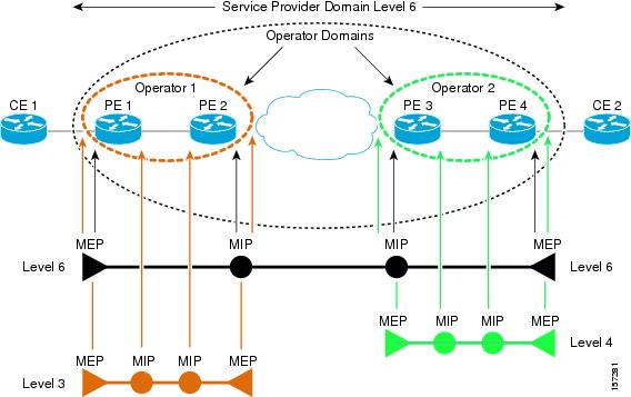
Maintenance Domains
Ethernet CFM, within any given service provider network, relies on a functional model consisting of hierarchical maintenance domains. A maintenance domain is a management space on a network that is owned and operated by a single entity and defined by a set of internal boundary ports. A domain is assigned a unique maintenance level which defines the hierarchical relationship of domains. Maintenance domains may nest or touch, but cannot intersect. If two domains nest, the outer domain must have a higher maintenance level than the one it engulfs. A single device might participate in multiple maintenance domains.
CFM Services
A CFM service (maintenance association) enables the partitioning of a CFM maintenance domain according to the connectivity within the network. For example, if the network is divided into a number of virtual LANs (VLANs), a CFM service is created for each of these. CFM can then operate independently in each service. A CFM service is always associated with the maintenance domain within which it operates, and therefore with that domain's maintenance level. All CFM frames relating to the service carry the maintenance level of the associated maintenance domain. There can be many CFM services within a domain. The CFM service must be configured on a domain before MEPs can be configured.
Maintenance Points
A maintenance point demarcates an interface that participates in a CFM maintenance domain. A maintenance point is an instance of a particular CFM service on a specific interface. CFM only operates on an interface if there is a CFM maintenance point on the interface. A maintenance point is always associated with a particular CFM service, and therefore with a particular maintenance domain at a particular level. Maintenance points generally only process CFM frames at the same level as their associated maintenance domain. Frames at a higher maintenance level are always forwarded transparently, while frames at a lower maintenance level are normally dropped. This helps enforce the maintenance domain hierarchy and ensures that CFM frames for a particular domain cannot leak out beyond the boundary of the domain. There are two types of maintenance points:
- Maintenance endpoints (MEPs)—Created at the edge of the domain. Responsible for confining CFM messages within the domain. Maintenance end points (MEPs) are members of a particular service within a domain and are responsible for sourcing and sinking CFM frames. They periodically transmit continuity check messages and receive similar messages from other MEPs within their domain. They also transmit traceroute and loopback messages at the request of the administrator.
- Maintenance intermediate points (MIPs)—Internal to the domain. A MIP will forward CFM packets while MEPs do not forward CFM packets because they must keep them within the domain. MIPs are not explicitly configured on each interface. MIPs are created automatically according to the algorithm specified in the CFM 802.1ag standard.
Configure CFM Maintenance Domains and Maintenance Associations (Services)
To enable CFM in your network, you need to create the relevant maintenance domains and define the maintenance points participating in the maintenance domain. For each device, you specify to which maintenance domain it belongs by assigning a maintenance domain level. You then define the CFM services, where you associate MEPs with the maintenance domain, that is, the interfaces on the device that belong to the maintenance domain.
To configure CFM on a device:
For Cisco IOS and Cisco IOS-XE devices:
interface <type of interface, gigabit/tengigabit> <interface number>
	service instance <service instance number, for example 1> ethernet
                encapsulation dot1q 1 <vlan id>
| Step 1 | Choose Inventory > Network Devices from the left sidebar. |
| Step 2 | Locate the required device in the list of devices and click the device name hyperlink to open the device details window. |
| Step 3 | Click the Configuration tab, then click the Logical View left side tab. |
| Step 4 | Choose EOAM > CFM. |
| Step 5 | In the CFM window, click the '+' icon to add a new CFM domain. |
| Step 6 | Enter the
following information:
|
| Step 7 | Click Save. The row is added to the table and the configurations are deployed to the device. Now you can define the CFM services and associate end points to the configured maintenance domain. Once the configuration is deployed to the device, you can edit only the MEP Archive Hold Time value in the row. The other values cannot be modified. |
| Step 8 | Locate the maintenance domain name you just created in the table and click on the Maintenance Domain name hyperlink. |
| Step 9 | Click the Services tab to add service details. |
| Step 10 | Enter a name for the CFM service. |
| Step 11 | For IOS
devices: Enter a bridge domain name.
For IOS-XR devices: Enter the X-connect group name and the name of the point to point connection within the cross connect group. |
| Step 12 | Change the interval (10 to 600000 ms) between messages using the Continuity Check Interval drop-down menu. |
| Step 13 | Locate the CFM service you just created in the table and click on the MEP hyperlink. This link was enabled when you saved the details. |
| Step 14 | In the
MEP tab, specify the interfaces that will serve as
the MEPs in the Maintenance Entity Group. These are the interfaces on the
device that belong to the specified maintenance domain, have the same level,
and are on the same service provider VLAN (S-VLAN).
If the Interface drop-down menu is empty, ensure that the device is configured with the pre-requisites mentioned above. |
| Step 15 | For each MEP, enter the MEP ID (a value between 1 and 8191). |
| Step 16 | Click Save to save your MEP definitions and close the dialog. To verify that your changes were saved, navigate to Inventory > Network Devices, and in the Configuration tab, click EOAM > CFM and view the maintenance domain details. |
Delete a CFM Domain
You can delete CFM domains that have been created using Cisco EPN Manager. To delete a CFM domain:
| Step 1 | Choose Inventory > Network Devices from the left sidebar. |
| Step 2 | Locate the required device in the list of devices and click the device name hyperlink to open the device details window. |
| Step 3 | Click the Configuration tab, then click the Logical View left side tab. |
| Step 4 | Choose EOAM > CFM. |
| Step 5 | Select the domain that you want to delete and in the CFM window, click the 'X' icon to delete it. This deletes the configured maintenance domain both from the table and from the device. If the domain has defined CFM services and associated end points, then you will need to disassociate the services and the end points before deleting the domain. |
Perform EOAM Connectivity and Performance Checks
Cisco EPN Manager provides predefined EOAM-related configuration templates that can be used to monitor the connectivity and performance of virtual connections (VCs) in a Carrier Ethernet network.
To use these templates, from the left sidebar, choose , then choose .
The following table lists the available EOAM configuration templates, their purpose, and the mandatory input parameters you are required to provide.
Note | To see the results and/or output of template deployment, check the job details that are displayed when you deploy a change. |
|
Template Name |
Use it to... |
Essential Input Values |
Additional Information |
|---|---|---|---|
|
EOAM-CCDB-Content- IOS |
Display the contents of a maintenance intermediate point (MIP) continuity check database (CCDB) in order to verify CFM operation or to check how EOAM has been set up in the network. |
None of the fields are mandatory. Domain ID: Choose the way in which you want to identify the maintenance domain and enter a value in the corresponding field. Service: Specify a maintenance association within the domain, based on ICC MEG identifier, VLAN ID or VPN ID. |
|
|
EOAM-CCDB-Content- IOS-XR |
Display the contents of a maintenance intermediate point (MIP) continuity check database (CCDB) in order to verify CFM operation or to check how EOAM has been set up in the network. |
None of the fields are mandatory. Node ID: The CFM CCM learning database for the designated node, entered in the rack/slot/module notation. |
|
|
EOAM-CFM-Ping-IOS and EOAM-CFM-Ping- IOS-XR |
Check connectivity to a destination MIP or MEP using CFM loopback messages. |
Ping Destination Type: Identify the destination MEP, either by MAC address or MEP ID. Choose Multicast if there are multiple destination MEPs. Maintenance domain name for destination MEP: The name of the domain where the destination MEP resides. |
|
|
EOAM-CFM-Traceroute- IOS |
IOS devices: Trace the route to a destination MEP to check the number of hops and the connectivity between hops. |
Destination Type: Identify the destination MEP, either by MAC address or MEP ID. Maintenance domain name for destination MEP: The name of the domain where the destination MEP resides. Service Type: Identify the maintenance association (MA) within the domain, either by name, ITU carrier code (ICC), MA number, VLAN ID, or VPN ID. |
|
|
EOAM-CFM-Traceroute- IOS-XR |
IOS-XR devices: Trace the route to a destination MEP to check the number of hops and the connectivity between hops. |
Maintenance domain name for destination MEP: The name of the domain where the destination MEP resides. Service Name: The name of the service instance being monitored by the Maintenance Association (MA) within the specified maintenance domain. Destination Type: Identify the destination MEP, either by MAC address or MEP ID. Source MEP ID: Identify the maintenance association (MA) within the domain, either by name, ITU carrier code (ICC), MA number, VLAN ID, or VPN ID. Source Interface Type: The source interface type of the locally defined CFM MEP. Interface Path ID: The physical or virtual interface name. |
|
|
EOAM-Configure-Y- 1731-PM-On-Demand- Operation-CFM-Loopback- IOS-XR |
Configure an on-demand Ethernet SLA operation for CFM loopback. By default, measures two-way delay and jitter. |
Probe Domain: Check the checkbox to enable the probe. Domain Name: The name of the maintenance domain for the locally defined CFM MEP. Domain Interface Type: The source interface type of the locally defined CFM MEP. Domain Interface Path ID: The physical or virtual interface name. Domain MAC Address or MEP-ID: Choose whether you want to identify the domain by MAC address or by MEP ID and provide the necessary information in the relevant field below. For MEP ID, enter an ID from 1 to 8191. |
Optionally, you can specify the type of statistics to measure, whether or not to use bins for aggregate type, probe frequency and duration values, and more. The values you specify will override the default actions. |
|
EOAM-Configure-Y- 1731-PM-On-Demand- Operation-CFM-Synthetic- Loss-Measurement-IOS- XR |
Configure an on-demand Ethernet SLA operation for CFM synthetic loss measurement. By default, measures one-way Frame Loss Ratio (FLR) in both directions. |
Probe Domain: Check the checkbox to enable the probe. Domain Name: The name of the maintenance domain for the locally defined CFM MEP. Domain Interface Type: The source interface type of the locally defined CFM MEP. Domain Interface Path ID: The physical or virtual interface name. Domain MAC Address or MEP-ID: Choose whether you want to identify the domain by MAC address or by MEP ID and provide the necessary information in the relevant field below. For MEP ID, enter an ID from 1 to 8191. |
Optionally, you can specify the type of statistics to measure, whether or not to use bins for aggregate type, probe frequency and duration values, and more. The values you specify will override the default actions. |
|
EOAM-Configure-Y- 1731-PM-On-Demand- Operation-FM-Delay- Measurement-IOS-XR |
Configure an on-demand Ethernet SLA operation for CFM delay measurement. By default, measures one-way delay and jitter in both directions, and two-way delay and jitter. |
Probe Domain: Check the checkbox to enable the probe. Domain Name: The name of the maintenance domain for the locally defined CFM MEP. Domain Interface Type: The source interface type of the locally defined CFM MEP. Domain Interface Path ID: The physical or virtual interface name. Domain MAC Address or MEP-ID: Choose whether you want to identify the domain by MAC address or by MEP ID and provide the necessary information in the relevant field below. For MEP ID, enter an ID from 1 to 8191. |
Optionally, you can specify the type of statistics to measure, whether or not to use bins for aggregate type, probe frequency and duration values, and more. The values you specify will override the default actions. |
|
EOAM-Configure-Y- 1731-PM-Direct-On- Demand-IOS |
Perform real-time troubleshooting of Ethernet services in direct mode where an operation is created and run immediately. |
Frame Type: The type of frame, either DMMv1 (frame delay) or SLM (frame loss). Domain Name: The name of the maintenance domain for the locally defined CFM MEP. EVC or VLAN: Identify the EVC or VLAN on which the test will be performed. The VLAN ID can be between 1 and 4096. Target MPID or MAC Address: Identify the MEP at the destination, either by MPID (1 to 8191) or by MAC Address. CoS Value: The class of service level (0-7) that will be applied to the CFM message for the specified MEP. Local MPID or MAC Address: Identify the MEP at the source, either by MPID (1 to 8191) or by MAC Address. Burst or Continuous: Specify whether a continuous stream of frames or bursts of frames will be sent during the on-demand operation. Aggregation Period: Specify the length of time in seconds during which the performance measurements are conducted, after which the statistics are generated (1-900). |
|
|
EOAM-Configure-Y- 1731-PM-Referenced-On- Demand-IOS |
Perform real-time troubleshooting of Ethernet services in referenced mode where a previously configured operation is started and run. |
Frame Type: The type of probe, either DMMv1 or SLM. Operation Number: The number of the operation being referenced. |
|
|
Remove-CFM-MEP- IOS |
Remove the MEP configuration from the device. |
Interface Name, Service Instance Number,EVC Name. |
|
|
Remove-CFM-MEP- IOSXR |
Remove the MEP configuration from the device. |
Interface Name, Domain Name. |
|
|
Remove-CFM- Service-IOS |
Remove the CFM service. |
Interface Name, Service Instance Number, EVC Name, Domain Name, Level, Service Name. |
Configure Quality of Service (QoS)
Quality of Service (QoS) is a set of capabilities that allow the delivery of differentiated services for network traffic. QoS features provide better and more predictable network service by:
-
Giving preferential treatment to different classes of network traffic.
-
Supporting dedicated bandwidth for critical users and applications.
-
Controlling jitter and latency (required by real-time traffic).
-
Avoiding and managing network congestion.
-
Shaping network traffic to smooth the traffic flow.
-
Setting traffic priorities across the network.
Using Cisco EPN Manager you can configure QoS on Carrier Ethernet interfaces. Before the appropriate QoS actions can be applied, the relevant traffic must be differentiated by creating classification profiles, or class maps. Packets arriving at the device are checked against the match criteria of the classification profile to determine if the packet belongs to that class. Matching traffic is subjected to the actions defined in an action profile, or policy map.
To configure classification profiles and action profiles, choose Configuration > QoS > Profiles from the left sidebar.
This section includes the following topics:
- Create a QoS Classification Profile
- Create a QoS Action Profile
- Check Which QoS Profiles are Configured on a Device
- Apply a QoS Action Profile to Interface(s)
- Import QoS Profiles Discovered from Devices
- Dissociate a QoS Action Profile from Multiple Interfaces
Create a QoS Classification Profile
Create classification profiles (class maps) to differentiate traffic into different classes so that certain actions can be applied to traffic that matches the classification criteria.
To create a classification profile:
| Step 1 | Choose Configuration > QoS > Profiles in the left sidebar. | ||||||||||||||||||||||||||||||||||||||||||||||||||
| Step 2 | Click the Add (“+”) icon at the top of the Global QoS Classification Profiles pane. | ||||||||||||||||||||||||||||||||||||||||||||||||||
| Step 3 | Enter a unique name for the classification profile. The name should reflect the classification criteria defined in the profile for easy identification. For further clarification, you can add a description. | ||||||||||||||||||||||||||||||||||||||||||||||||||
| Step 4 | Define the matching criteria for the profile: | ||||||||||||||||||||||||||||||||||||||||||||||||||
| Step 5 | Under QoS Classifications, click the plus icon to define classification criteria for the classification profile. | ||||||||||||||||||||||||||||||||||||||||||||||||||
| Step 6 | Select an
action based on which the traffic will be classified, then click in the Value
column and provide the relevant value, as follows:
| ||||||||||||||||||||||||||||||||||||||||||||||||||
| Step 7 | Define additional QoS classifications, as required. | ||||||||||||||||||||||||||||||||||||||||||||||||||
| Step 8 | Click the Save button at the bottom of the window to save the profile. A notification in the bottom right corner will confirm that the profile has been saved and the profile will appear in the list of profiles on the left. | ||||||||||||||||||||||||||||||||||||||||||||||||||
| Step 9 | Select the profile from the list and click the Deploy button to initiate deployment of the profile to devices. | ||||||||||||||||||||||||||||||||||||||||||||||||||
| Step 10 | If you want to create a new profile with the details of an existing Classification Profile , click the Clone button. This profile will have the name of the classification profile that you cloned from, and the suffix -clone. You can edit the name, matching criteria and any other details of this cloned profile. | ||||||||||||||||||||||||||||||||||||||||||||||||||
| Step 11 | If you want the selected profile to override any other class map that already exists on the device, check the Override existing configuration check box. If this check box is not checked, the profile will be merged with the configurations on the device. | ||||||||||||||||||||||||||||||||||||||||||||||||||
| Step 12 | Select the device(s) to which you want to deploy the QoS Classification profile. | ||||||||||||||||||||||||||||||||||||||||||||||||||
| Step 13 | Schedule the deployment, if required. | ||||||||||||||||||||||||||||||||||||||||||||||||||
| Step 14 | Click Submit. A notification in the bottom right corner will confirm that the profile has been deployed. To check the status of the deployment job, choose Administration > Job Dashboard from the left sidebar. Select the relevant job to view the job details and history in the lower section of the window. Click the Information icon for further details. |
Create a QoS Action Profile
Create action profiles (policy maps) to specify the actions to be applied to traffic belonging to a specific traffic class.
To create an action profile:
| Step 1 | Choose Configuration > QoS > Profiles from the left sidebar. |
| Step 2 | From the QoS Profiles pane on the left, choose, User Defined Global QoS Profiles > Action Profiles. |
| Step 3 | Click the Add (“+”) icon at the top of the Create Action Profile pane |
| Step 4 | Enter a unique name for the action profile, and enter a description, if required. |
| Step 5 | Select the classification profiles for which you want to assign actions. Under Classification Profiles, click the plus icon, select the required profile(s) from the list, and click OK. |
| Step 6 | Select the
Classification Profile (class map) and define the actions to be applied if
traffic matches the profile. You can define Policing, Marking, Queuing,
Shaping, RED actions, and Service Policy (H-QoS). There is a tab for each of
these action types and its definitions, as follows:
|
| Step 7 | Click the Save button at the bottom of the window to save the profile. A notification in the bottom right corner will confirm that the profile has been saved and the profile will appear in the list of profiles on the left. |
| Step 8 | From the Global QoS Action Profiles pane, select the profile, and click the Deploy button to initiate deployment of the profile to devices. |
| Step 9 | If you want to create a new profile with the details of an existing Action Profile , click the Clone button. This profile will have the name of the action profile that you cloned from, and the suffix -clone. You can edit the name, actions and any other details of this cloned profile. |
| Step 10 | If you want the selected profile to override any other policy map that already exists on the device, check the Override existing configuration check box. If this check box is not checked, the profile will be merged with the configurations on the device. |
| Step 11 | Select the device(s) to which you want to deploy the QoS Action profile. |
| Step 12 | Schedule the deployment, if required. |
| Step 13 | Click Submit. A notification in the bottom right corner will confirm that the profile has been deployed. To check the status of the deployment job, choose Administration > Job Dashboard from the left sidebar. Select the relevant job to view the job details and history in the lower section of the window. Click the Information icon for further details. |
Check Which QoS Profiles are Configured on a Device
To see the QoS profiles that have been deployed to a specific device:
| Step 1 | Choose Inventory > Network Devices from the left sidebar. |
| Step 2 | Locate the required device and click on the device name hyperlink to display the device details. |
| Step 3 | Click the Configuration tab, then click the Logical View left side tab. |
| Step 4 | Click on the arrow next to QoS in the left pane, and select either Action Profiles or Classification Profiles. A table listing the profiles that have been deployed to the selected device is displayed. Click on the profile name (blue hyperlink) to display the details of the profile. |
Apply a QoS Action Profile to Interface(s)
You can select an action profile deployed to a device and apply it to multiple interfaces on that device. An action profile enables you to specify the actions to be applied to traffic belonging to a specific traffic class. Before applying an existing profile to interfaces, you can modify the profile or use it to create a new profile. When you choose an interface that has an action profile already applied to it, Cisco EPN Manager notifies you about it and enables you to override the existing profile. To be able to apply an action profile to interfaces, you first need to ensure that the required profile has been deployed to the device. To do this, see Create a QoS Action Profile.
To apply an action profile to interfaces:
| Step 1 | Choose from the left sidebar.
Cisco EPN Manager interfaces are displayed under the categories Ethernet CSMA/CD, IEEE8023 ADLAG, Gigabit Ethernet, and L2 VLAN. All other ports are displayed under the User Defined category. | ||
| Step 2 | Select the interfaces that you want to associate to an Action profile. | ||
| Step 3 | Click
Associate Action Profile to select the action
profile and to set the direction in which it must be applied.
The available action profiles list and the interfaces it can be applied to are listed. The interfaces are listed by their name, application direction, and the action profiles that already exist on the interface. | ||
| Step 4 | Select the required action profile from the Action Profiles drop-down menu. If the menu is empty, you need to create action profile and then try to associate them with devices. See, Create a QoS Action Profile. | ||
| Step 5 | In the
Interfaces section, specify the direction in which
the profile is to be applied. While applying a profile to a sub-interface,
ensure that it is applied in a direction opposite to that of the main
interface. To change the applied direction, use the
Edit icon at
the top left corner of the dialog.
| ||
| Step 6 | (Optional) You can also schedule the application of the selected action profile to a later date and time. To do this, expand the Schedule section and specify the date and time and frequency for when you the profile to be applied. This task can further be edited on the Jobs page if required. | ||
| Step 7 | Click
OK to apply the action profile to the selected
devices. A notification at the bottom right corner of the dialog will confirm
whether the profile has been successfully applied or if the job failed. Click
the
Show
Details link for more information.
To dissociate action profiles from the interfaces they are applied to, see Dissociate a QoS Action Profile from Multiple Interfaces |
Import QoS Profiles Discovered from Devices
You can import QoS profiles discovered from the device directly into Cisco EPN Manager . Once the QoS profiles are imported, they can be edited and further configured on the device using Cisco EPN Manager . Profiles which are discovered from the device with profile names that match other profiles already present in Cisco EPN Manager are represented as Global profiles. This is indicated in the Global column in the Global Profiles page. Note that Global profiles could have the same names but different QoS configuration. While importing global profiles, you can choose to either overwrite the existing profile (with the same name) using the discovered profile or you can rename the profile before you import it.
To import QoS profiles discovered from devices:
| Step 1 | Choose from the left sidebar to display all Cisco EPN Manager QoS profiles. |
| Step 2 | To import Action profiles, from the QoS Profiles pane on the left, choose, . |
| Step 3 | To import Classification profiles, from the QoS Profiles pane on the left, choose, . |
| Step 4 | To first select
a device and choose the profiles discovered on that device:
|
| Step 5 | Select the profiles that you want to import and click Import. To ensure that you are importing profiles that are not already present on the device, choose profiles that are not Global (marked as No in the Global column). |
| Step 6 | If there are duplicate profiles present in Cisco EPN Manager , you are asked to either rename the profile to create a profile with a new name and the same QoS configuration or overwrite the existing profile. Make the required changes. |
| Step 7 | If you want to create a new profile with the details of an existing QoS Profile , click the Clone button. This profile will have the name of the QoS profile that you cloned from, and the suffix -clone. You can edit any details of this cloned profile. |
| Step 8 | Click Save to import the selected QoS profiles. To apply the imported profiles to a given device's interfaces, see, Apply a QoS Action Profile to Interface(s). |
Dissociate a QoS Action Profile from Multiple Interfaces
An action profile enables you to specify the actions to be applied to traffic belonging to a specific traffic class. You can select an action profile deployed to a device and apply it to multiple interfaces on that device. After you have applied the profile to the interfaces, you can choose to dissociate them from those interfaces if required. To dissociate an action profile from interfaces, you first need to ensure that the required profile has been applied to the device. See Apply a QoS Action Profile to Interface(s).
To apply an action profile to interfaces:
| Step 1 | Choose
from the left sidebar.
Alternatively, you can navigate to Configuration > QoS > Profiles to first select the profile before dissociating it from the interfaces it is applied to. Cisco EPN Manager interfaces are displayed under the categories Ethernet CSMA/CD, IEEE8023 ADLAG, and L2 VLAN. All other ports are displayed under the User Defined category. |
| Step 2 | Select the interfaces from which you want to dissociate the action profile. |
| Step 3 | Click Dis-associate Action Profile. |
| Step 4 | (Optional) You can also schedule the de-association of action profiles to a later date and time. To do this, expand the Schedule section and specify the date, time, and frequency based on which the profiles must be dissociated. |
| Step 5 | Click OK to confirm. The selected interfaces are dissociated from the action profiles that were applied to them. A notification at the bottom right corner of the window will confirm whether the profile has been successfully dissociated or if the job failed. Click the Show Details link for more information. |
Launch Cisco Transport Controller to Manage Cisco NCS and Cisco ONS Devices
The Cisco Transport Controller (CTC) is the software interface for a subset of Cisco ONS and Cisco NCS devices. CTC is a Java application that resides on the control cards. It is used to provision and administer these devices.
You can launch CTC from Cisco EPN Manager. Only the latest CTC release is launched, regardless of the NE release you selected. If you need to use other CTC releases, launch CTC from a web browser and connect directly to the NE that has the required CTC release.
To launch CTC:
Make sure the devices are properly configured to launch CTC. See Configure Devices So They Can Be Modeled and Monitored.
| Step 1 | From the left sidebar, choose Inventory > Device Management > Network Devices. |
| Step 2 | Click the “i” icon next to the Cisco ONS or Cisco NCS 4000 device’s IP address to launch the Device 360 view. |
| Step 3 | In the Device 360 view, choose Actions > Launch CTC. The CTC launcher application is downloaded to your computer. |
| Step 4 | In the CTC
Launcher window, choose one of the following connection mode:
|
| Step 5 | Select the CTC Version, and then click Launch CTC. |
| Step 6 | Enter your CTC credentials. |
 Feedback