Improve Application Performance With Application Visibility and Control (AVC)
Use configuration templates in Cisco Prime Infrastructure to design the set of device configurations that you need to set up the devices in a branch or change the feature configuration for a device from the Device Work Center.
Set Up Devices to Use AVC Features with WSMA
Prime Infrastructure mainly uses the CLI method (over Telnet or SSHv2) to configure the devices. You can use WSMA (over SSHv2) for configuring specific features on the ASR and ISR devices. Cisco Web Services Management Agent is a more efficient and more robust method to configure the devices. Prime Infrastructure supports Zone Based Firewall and Application Visibility configuration via WSMA on the ASR and ISR devices.
To configure Zone Based Firewall or Application Visibility via WSMA, follow these steps:
Procedure
| Step 1 |
Add or edit the device in Prime Infrastructure to use SSHv2 (rather than Telnet) as the management transport protocol.
|
| Step 2 |
If the device is also managed by Prime Infrastructure which is not configured to use SSH2, edit the device credentials:
|
| Step 3 |
Activate a WSMA profile on the device by configuring a WSMA configuration profile as follows: Example: |
| Step 4 |
Configure a configuration archive, which will be used by WSMA for handling transactional configurations and rollbacks by using the following CLI commands on the device: Example: |
What is AVC
The Application Visibility feature allows you to monitor traffic on specific interfaces and generate performance and bandwidth-statistics reports that supply information to the various dashlets and reports in Cisco Prime Infrastructure. Devices send these reports to Cisco Prime Infrastructure, and each report supplies information to a subset of the Cisco Prime Infrastructure dashlets and reports. Cisco Prime Infrastructure can configure Application Visibility either through CLI (over Telnet or SSH) or through WSMA. Application Visibility can be configured through WSMA in a more efficient and robust method and we recommend that you use the WSMA protocols for configuring Application Visibility. For more information on using WSMA with Cisco Prime Infrastructure.
To simplify configuration, the Application Visibility feature is split into four types of metric and NetFlow reports:
|
Report |
Description |
||
|---|---|---|---|
|
Traffic Statistics |
Sends the statistics on the bandwidth consumed by each of the NBAR-recognized applications on a per-user and per-interface basis. This report supplies information to the various application bandwidth dashlets and reports in Cisco Prime Infrastructure as “Top N Applications”, “Application Bandwidth reports”, “Top N clients”, and so on. |
||
|
HTTP URL Visibility |
Sends performance and bandwidth reports for HTTP-based traffic, and this report supplies information to various URL dashlets and reports in Cisco Prime Infrastructure as “Top N URL by hits” and “Top N URL by response time”.
|
||
|
Application Response Time |
Sends performance-related information for TCP traffic, and this report supplies information to various response time dashlets and reports in Cisco Prime Infrastructure as “applications ART analysis”, “worst N clients by transaction time”, and so on. |
||
|
Voice/Video Metrics |
Sends various RTP key-performance indicators for RTP-based voice/video traffic, and supplies information to dashlets and reports in Cisco Prime Infrastructure under the voice/video category as “worst N RTP streams by packet lost.” |
Supported Devices for AVC
The Application Visibility feature is supported on the following platforms:
- ASR 1000 series platform from Cisco IOS-XE Release 15.3(1)S1 or later
- ISR G2 platform from Cisco
IOS Release 15.2(4)M2 or later as listed below:
- Cisco 1900 Series Integrated Services Routers
- Cisco MWR 1900 Mobile Wireless Routers
- Cisco 2900 Series Integrated Services Routers
- Cisco 3900 Series Integrated Services Routers
- Cisco 812 CiFi Integrated Services Routers
- Cisco 819 Non-Hardened Integrated Services Router
- Cisco 819 Hardened Integrated Services Router
- Cisco 819 Hardened 3G - Dual Radio 802.11n WiFi ISR
- Cisco 861,861W Integrated Services Router G2
- Cisco 867,867W Integrated Services Router G2
- Cisco 866VAE Integrated Services Router
- Cisco 880 3G Integrated Services Router G2
- Cisco 881,881W Integrated Services Router G2
- Cisco 881SRST,881SRSTW Integrated Services Router G2
- Cisco 881W,881WD Integrated Services Router
- Cisco 886,886W Integrated Services Router G2
- Cisco 886SRST,886SRSTW Integrated Services Router G2
- Cisco 886VA,886VAG Integrated Services Router G2
- Cisco 886VA-W Integrated Services Router G2
- Cisco 887,887W Integrated Services Routers G2
- Cisco 887V Integrated Services Router G2
- Cisco 886VA Integrated Services Router G2
- Cisco 887VA M Integrated Services Router G2
- Cisco 887VA-W Integrated Services Router G2
- Cisco 888,888W,888GW Integrated Services Router G2
- Cisco 888ESRST,888ESRSTW Integrated Services Router G2
- Cisco 888E,888EW Integrated Services Router G2
- Cisco 888EA Integrated Services Router G2
- Cisco 888SRST,888SRSTW Integrated Services Router G2
- Cisco 891,891W Integrated Services Router G2
- Cisco 892,892W Integrated Services Router G2
- Cisco 892F,892FW Integrated Services Router
- Cisco C892FSP Integrated Services Router
- Cisco C897VA Integrated Services Router
- Cisco C897VAW Integrated Services Router
- Cisco C891F Integrated Services Routers
- Cisco C881 Integrated Services Router
- Cisco C899 Secure Gigabit Ethernet with Multi-mode 4G LTE Router
- Cisco 800M with 4-Port LAN Integrated Services Router
- Cisco 800M with 8-Port LAN Integrated Services Router
- Cisco C896VA Integrated Services Router
- Cisco Integrated Services Virtual Router (ISRv) platform from Cisco IOS-XE Release 16.3 or later
-
Cisco ISR 1000 platform from Cisco IOS-XE Release 16.6.1 or later
- Cisco ISR 4200, 4300 and 4400 series platform from Cisco IOS-XE Release 15.3(2)S or later
- CSR platform from Cisco IOS-XE Release 15.3(2)S or later
Prerequisites for Using Application Visibility and Control
Activating the Application Visibility feature can impact device performance. To minimize the potential impact, the template allows you to select the traffic interfaces to monitor and the reports to generate.
Application Visibility is configured differently on different platforms and IOS releases. Newer IOS releases provide new mechanisms with better performance for setting up the Application Visibility and Control (AVC). Thus when upgrading an ASR 1000, CSR or ISR 4400 platforms running IOS-XE release prior to 15.4(1)S to an IOS-XE release 15.4(1)S or later, or when upgrading an ISR-G2 platform running IOS release prior to 15.4(1)T to IOS release 15.4(1)T or later, we recommend that you re-configure the AVC on these devices.
To configure application visibility in your network:
- (Optional) Set up WSMA on the devices to assure that the devices is configured via the WSMA protocol, rather than CLI. WSMA provides a more robust configuration mechanism.
- Make sure that your devices are running an up-to-date NBAR protocol packs.
- Estimate the potential resources impact on the device (CPU and memory) before activating application visibility on the device.
Activate application visibility on the device, either by creating a template and pushing it across the network, or by enabling AVC on an interface from the Device Work Center.
 Note |
To know the visibility into application traffic flows, see https://www.cisco.com/c/dam/en/us/td/docs/solutions/CVD/Aug2014/CVD-ApplicationMonitoringUsingNetFlowDesignGuide-AUG14.pdf |
Estimate CPU, Memory and Network Resources on ASR Devices
The Readiness Assessment feature allows you to estimate CPU consumption, memory usage, and NetFlow export traffic when you deploy application visibility features on an ASR device. DRE helps you analyze the demands for these resources on ASR devices based on typical predefined traffic profiles and device interface speeds.
DRE is supported on all ASRs running Cisco IOS-XE Release 15.3(1)S1 or later with one or more of these modules installed:
- cevModuleASR1000ESP5
- cevModuleASR1000ESP10
- cevModuleASR1000ESP20
- cevModuleASR1001ESP
- cevModuleASR1002FESP
To estimate the resource utilization on a specific device, follow these steps:
Procedure
| Step 1 |
Choose Services > Application Visibility and Control > Readiness Assessment. |
| Step 2 |
In the Interface column for the device that you want estimates on, click the down arrow icon. The list shows only those interfaces supporting Application Visibility capability. |
| Step 3 |
Select Internet Profile or Enterprise Profile. The device resource estimation is based on a typical traffic profile. Select “Internet Profile” for typical service-provider traffic, or “Enterprise Profile” for a typical enterprise-traffic. |
| Step 4 |
Select the interfaces for which you want to estimate the resource utilization. Speeds shown are those currently configured for each interface. If you want to base the estimate on a different speed, click Speed (Mbps) and enter a different value. |
| Step 5 |
Click Get Estimates. The Estimated Resource Usage graph displays the current, additional, and total usage of the CPU and memory, along with the threshold limit for these resources. The estimated and maximum NetFlow export traffic are also given. For devices on which AVC is already enabled, only the current and additional usage is shown. If resource usage is crossing threshold limits, optimize the problem device by:
|
View DMVPN Details of Routers
To view the DMVPN details of routers, do the following:
Procedure
| Step 1 |
Choose to view the details of routers supporting DMVPN and the active spokes count. |
| Step 2 |
Click a device name to view the hub details including VRF, local tunnel IP, tunnel interface number and spokes count. |
| Step 3 |
Click the Show Spoke Details button to view the spoke details of the selected hub. |
What is an NBAR Protocol Pack
The ability of the device to produce application visibility reports is based on the NBAR technology; NBAR, or Network-Based Application Recognition, is a classification engine that recognizes and classifies a wide variety of protocols and applications, including web-based and other difficult-to-classify applications and protocols that use dynamic TCP/User Datagram Protocol (UDP) port assignments.
NBAR is updated frequently to support new applications and protocols, the software update for an NBAR is called a Protocol Pack.
Further information on NBAR protocol packs and information on how to upgrade NBAR protocol pack.
When you upgrade an NBAR protocol pack on the device, a corresponding Prime Infrastructure update should be performed to update Prime Infrastructure with the supported protocols/applications on the devices.
To achieve that there is a periodic Prime Infrastructure software update (UBF file) issues when new protocol packs are released. Once you upgrade the NBAR protocol pack on the device, you should use Prime Infrastructure software upgrade to make sure Prime Infrastructure is also updated with the latest protocols.
At every point of time the network may contain various platforms (ISR-G2/ASR) running different Cisco IOS software releases and different protocol pack releases. While we do not recommend that you have different protocol pack releases installed on different devices reporting application visibility reports simultaneously, Prime Infrastructure will be able to support this, by configuring only the supported subset of protocols/applications, defined as filtering conditions in your template, on each of the devices, when deploying an application visibility template across multiple devices running different versions of NBAR protocol packs.
For more information, see NBAR Configuration Guide
Create Application Visibility Templates
An application visibility monitoring policy is defined on a selected group of interfaces. When you define the template, ensure that you have defined an interface-role object which matches the group of interfaces on which you would like to monitor the traffic and generate NetFlow reports.
To create an Application Visibility template, follow these steps:
Procedure
| Step 1 |
Choose Configuration > Templates > Features & Technologies > Application Visibility > AVC Configuration. |
| Step 2 |
In the Template Basic area, enter a unique name and a description in the appropriate fields. |
| Step 3 |
In the Validation Criteria area, choose a device type from the list and enter the OS version. |
| Step 4 |
In the Template Detail area, choose an Interface Role from the drop-down list. The interface role designates the group of interfaces on which you can monitor the traffic and produce Application-Visibility reports. |
| Step 5 |
In the Traffic Statistics area, you can determine which traffic should be monitored to produce the traffic statistics reports, select the Off radio button if you do not want to collect the statistics on data packets.
|
| Step 6 |
In the HTTP URL Visibility area, you can select the traffic that should be monitored to produce the report. Select the Off radio button if you do not want to collect URL statistics.
|
| Step 7 |
In the Application Response Time area, you can determine the traffic that should be monitored to produce the application response time reports. Also, optionally set a sampling option for the reports. Select the Off radio button if you do not want to collect ART metrics. |
| Step 8 |
In the Voice/Video metrics area, you can determine the traffic that should be monitored to produce the voice/video reports. Select the Off radio button if you do not want to collect the voice/video metrics. |
| Step 9 |
Click Save as New Template. |
Enable Default Application Visibility on Interfaces
From the Device Work Center, you can view the reports that are generated on each of the interfaces and enable or disable a default Application Visibility configuration on selected interfaces.
When a device does not have an application visibility configuration deployed on it, or it has a default application visibility configuration deployed on it (if all metrics are collected with a set of default parameters), the Device Work Center allows you to enable or disable a default application visibility configuration on the device by selecting interfaces on the device and enabling or disabling the default configuration on the interfaces.
Note |
When you deploy an application visibility template to the device, the application visibility template configuration will overwrite the default application visibility configuration that was enabled from the Device Work Center. |
The default configuration collects all the possible visibility metrics on all applicable IPv4 traffic.
The Application Visibility feature is supported on the following platforms:
- ASR platform from Cisco IOS-XE Release 15.3(1)S1 or later
- ISR G2 platform from Cisco IOS Release 15.2(4)M2 or later
- ISR G3 platform from Cisco IOS-XE Release 15.3(2)S later
- CSR platform from Cisco IOS-XE Release 15.3(2)S later
- Cisco Integrated Services Virtual Router (ISRv) platform from Cisco IOS-XE Release 16.3 or later
-
Cisco ISR 1000 platform from Cisco IOS-XE Release 16.6.1 or later
Note |
Application Visibility is configured differently on the ASR platform running Cisco IOS-XE15.3(1)S1 in comparison to Cisco IOS-XE15.3(2)S or later releases. After an ASR platform Cisco IOS release is upgraded from Cisco IOS-XE15.3(1)S1 to Cisco IOS-XE Releases 15.3(2)S and later, we recommend that you reconfigure Application Visibility on those devices. |
To change the default application visibility configuration profile configured on the device, first disable the Application Visibility policy on all interfaces and then re-enable it on the selected interfaces with the new profile.
To enable or disable the default application visibility configuration on the specific interface, follow these steps:
Procedure
| Step 1 |
Choose Inventory > Device Management > Network Devices. |
||||||||
| Step 2 |
After choosing the device from list, click Configuration. The Feature Configuration pane appears. |
||||||||
| Step 3 |
Expand the App Visibility & controlfolder and choose App Visibility. |
||||||||
| Step 4 |
Do one of the following:
There are several options that can be displayed:
|
Troubleshoot Traffic Flows Using AVC
You can collect application visibility data on every flow that goes through the monitored interface. However, because this can have a significant impact on the device performance, application visibility data is collected in an aggregated manner. To further troubleshoot specific flows, you can activate the Application Visibility troubleshooting sessions on the device. The sessions are activated on specific interfaces and on specific traffic. They allow you to collect the non aggregated information on a flow-based level that supplies a raw-NetFlow report in Prime Infrastructure. This information can be used later to analyze specific flows.
The Application Visibility Troubleshooting feature allows you to:
- Create and activate a troubleshooting session on a specific interface
- Deactivate and delete a troubleshooting session on a specific interface
 Caution |
To avoid overloading the server, we recommend that you configure no more than ten active troubleshooting sessions. Application troubleshooting is not supported on the ISR-G2 platforms. |
Note |
Troubleshooting sessions are configured differently on the ASR platform running Cisco IOS-XE Release 15.3(1)S1 in comparison to Cisco IOS-XE Release15.3(2)S or later releases. After, an ASR platform Cisco IOS Release is upgraded from Cisco IOS-XE Release 15.3(1)S1 to Cisco IOS-XE Release 15.3(2)S or later, we recommend that you deactivate and reactivate active troubleshooting sessions on those devices. |
To troubleshoot Application Visibility, follow these steps:
Procedure
| Step 1 |
Choose Services > Application Visibility & Control > Application Troubleshooting. |
||
| Step 2 |
In the AVC Troubleshooting Session page, click Add and enter a session name. |
||
| Step 3 |
In the Source/Destination IPs field, click Edit, and choose the source and destination IP addresses from the drop-down list. You can select the IP traffic and collect Application Visibility troubleshooting information for that specific IP traffic. The options are: on all IPv6 traffic or on all IPv4 traffic or on specific IPv4 addresses/subnets. Also, you can select a list of IP constraint pairs. Each such pair designates a bi-directional symmetric condition on the source and destination IPs of the traffic. For example, the pair: Any IPv4 <=> IPv4 subnet 192.168.0.0/16 matches all of the flows from 192.168.0.0/16 to any other IP and vice-versa (all of the flows from any IP address to 192.168.0.0/16). You can add multiple pair conditions. |
||
| Step 4 |
To add more IP constraints in the format of IP source/destination pairs, click the + icon in the Select Source Destination dialog box.
|
||
| Step 5 |
Click OK. |
||
| Step 6 |
Choose the device from the Device Table list. |
||
| Step 7 |
Choose the interface from the Interface Table list. |
||
| Step 8 |
Choose the application from the object selector dialog box. When you choose the applications, you can have a combination of Categories, Sub-categories, Encrypted Applications, and Tunneled Applications from the available list. A maximum of 32 applications or categories or attributes can be selected. |
||
| Step 9 |
Click Save to automatically activate the session. |
||
| Step 10 |
After the troubleshooting session is activated, click Launch Report to generate the Raw NetFlow report. |
Activate AVC Troubleshooting Sessions
You can activate an inactive troubleshooting session or deactivate an existing troubleshooting session.
To activate or deactivate a troubleshooting session, follow these steps:
Procedure
| Step 1 |
Choose Services > Application Visibility & Control > Application Troubleshooting. |
| Step 2 |
Choose a troubleshooting session from the list and click Activate or Deactivate. |
| Step 3 |
Click Save. |
Edit AVC Troubleshooting Sessions
You can edit or delete an inactive troubleshooting session. (To edit or delete an active session, you must deactivate it first.)
To edit or delete a troubleshooting session, follow these steps:
Procedure
| Step 1 |
Choose Services > Application Visibility & Control > Application Troubleshooting. |
| Step 2 |
Do either of the following: |
Configure the Data Sources You Want AVC To Use
Prime Infrastructure depends on a variety of sources for accurate gathering and reporting of device, performance and assurance data. These sources include specialized monitoring devices such as NAMs, and protocols running on normal devices, such as Cisco Medianet, NetFlow, Flexible NetFlow, Network Based Application Recognition (NBAR), Performance Monitoring (PerfMon), and Performance Agent.
You will want to manage these sources to ensure that only the correct data is gathered from active sources. The Data Sources page allows you to review your current data sources, and delete those that are no longer active.
Use the Data Sources page to review Prime Infrastructure current data sources.
Procedure
| Step 1 |
Select Services > Application Visibility & Control > Data Sources. Prime Infrastructure displays a summary page that lists each data source’s:
|
| Step 2 |
For additional details on the Data Source’s configuration template or for a Device 360 view of the Exporting Device, click the “i” icon shown next to the Data Source or Exporting Device listing. |
| Step 3 |
To delete inactive Prime Infrastructure data sources select the checkbox next to the inactive data source you want to delete. |
| Step 4 |
Click Delete. |
| Step 5 |
Click OK to confirm the deletion. |
Configure AVC Data Deduplication
Data deduplication allows you to identify authoritative data sources for the corresponding location groups.
Prime Infrastructure stores all the data it receives about network usages from all the sources (including any duplicate data that it may receive from multiple sources). When you specify authoritative data sources, only the data from the specified source is displayed when you view a particular site.
The data deduplication page allows you to specify a data source per a specific site. For example if you have a Network analysis module (NAM) at a branch office as wel as Netflow data that is sent from the same branch, you can choose to see the site information as it is reported by the NAM or netflow data with authoritative data source.
The two authoritative data sources are:
- System detected—Based on the managed device product families. You can change the device family selection precedence. To change the precedence, click on the settings icon and drag and drop the device families. The authoritative datasources are selected according to this precedence.
- Customized—You can pick and choose from the managed data source.
Procedure
| Step 1 |
Choose Services > Application Visibility & Control > Data Deduplication. The Data Deduplication page appears. |
| Step 2 |
Click System Detected to identify the data sources in the location group or select the customized to select the data sources. |
| Step 3 |
Click Save. |
| Step 4 |
Click Apply. |
Configure VPN IKE Policies and Settings Using Configuration Templates
To create an IKE policies template, follow these steps:
Procedure
| Step 1 |
Choose Configuration >Templates > Features & Technologies > Security > VPN Components > IKE Policies. |
| Step 2 |
In the Template Basic area, enter a name, description, and tag for your template in the appropriate text boxes. |
| Step 3 |
In the Validation Criteria area, choose a Device Type from the drop-down list and enter the OS version. For more information about the required field descriptions, see the Cisco Prime Infrastructure Reference Guide. |
| Step 4 |
Click Save as New Template. |
Configure VPN IPSec Profiles Using Configuration Templates
To create an IPsec profile template, follow these steps:
Procedure
| Step 1 |
Choose Configuration >Templates > Features & Technologies > Security > VPN Components > IPSec Profile. |
| Step 2 |
In the Template Basic area, enter a name, description, and tag for your template in the appropriate text boxes. |
| Step 3 |
In the Validation Criteria area, choose a device type from the drop-down list and enter the OS version. |
| Step 4 |
In the Template Detail area, click Add Row and enter the required information. A transform set represents a certain combination of security protocols and algorithms. During the IPsec negotiation, the peers agree to use a particular transform set for protecting a particular data flow. A transform set describes a particular security protocol with its corresponding algorithms. For more information about the required field descriptions, see the Cisco Prime Infrastructure Reference Guide. |
| Step 5 |
Click Save as New Template. |
Configure VPN Preshared Keys Using Configuration Templates
To create a preshared keys template, follow these steps:
Procedure
| Step 1 |
Choose Configuration >Templates > Features & Technologies > Security > VPN Components > Preshared Keys. |
| Step 2 |
In the Template Basic area, enter a name, description, and tag for your template in the appropriate text boxes. |
| Step 3 |
In the Validation Criteria area, choose a Device Type from the drop-down list and enter the OS Version. |
| Step 4 |
In the Template Detail area, click Add Row and enter the required information. |
| Step 5 |
Click Save as New Template. |
Configure VPN RSA Keys Using Configuration Templates
To create RSA keys template, follow these steps:
Procedure
| Step 1 |
Choose Configuration > Templates > Features & Technologies > Security > VPN Components > RSA Keys. |
| Step 2 |
In the Template Basic area, enter a name, description, and tag for your template in the appropriate text boxes. |
| Step 3 |
In the Validation Criteria area, choose a device type from the drop-down list and enter the OS version. |
| Step 4 |
In the Template Detail area, click Add and enter the required information. |
| Step 5 |
Select the Exportable box to generate RSA as an exportable key, then click OK. |
| Step 6 |
Click Save as New Template. |
Configure VPN Transform Sets Using Configuration Templates
To create a transform sets template, follow these steps:
Procedure
| Step 1 |
Choose Configuration >Templates > Features & Technologies > Security > VPN Components > Transform Sets. |
||
| Step 2 |
In the Template Basic area, enter a name, description, and tag for your template in the appropriate text boxes. |
||
| Step 3 |
In the Validation Criteria area, choose a device type from the drop-down list and enter the OS version. |
||
| Step 4 |
In the Template Detail area, click Add Row and enter the required information.
|
||
| Step 5 |
Click Save as New Template. |
Classify Netflow Data Using Endpoint Association
Prime Infrastructure classifies and displays the Netflow data site wise in Network Health and Service Health page. Endpoint Association helps you to create rule for classifying incoming client/server IP’s, depending on their subnet and/or data source.
Note |
To assign devices or Client/Server IP’s to specific Location groups, the location group should be defined in . |
To create a rule:
Procedure
| Step 1 |
Go to . |
||
| Step 2 |
Click + (Add Row) icon to create a new rule. |
||
| Step 3 |
Choose the required location from the Location Group drop-down list. |
||
| Step 4 |
Provide the valid subnet in the Subnet field. |
||
| Step 5 |
(Optional) Choose the required data source from the Data Source drop-down list. |
||
| Step 6 |
Click Save. The rule is created. Whenever there is a Netflow, the client/server IP in the UDP payload gets classified according to the rule created..
|
View NetFlow Templates
Netflow templates define the metadata/structure that is used to process incoming UDP packets. These templates specify the metrics to be collected from the devices. Prime Infrastructure allows you to view the defined templates from . You can configure the template either through AVC Profile in Application Control Page or through CLI manually.
Custom Reports option in the NetFlow Templates page is deprecated from Cisco Prime Infrastructure Release 3.2, due to high disk space usage. You can generate the report from the Reports > Reports Launchpad > Raw NetFlow page.
What Is An Easy VPN Server
Cable modems, xDSL routers, and other forms of broadband access provide high-performance connections to the Internet, but many applications also require the security of VPN connections that perform a high level of authentication and that encrypt the data between two particular endpoints. However, establishing a VPN connection between two routers can be complicated and typically requires tedious coordination between network administrators to configure the VPN parameters of the two routers.
The Cisco Easy VPN Remote feature eliminates much of this tedious work by implementing Cisco Unity Client Protocol, which allows most VPN parameters to be defined at a Cisco IOS Easy VPN server. This server can be a dedicated VPN device; for example, any of the following:
- Cisco VPN 3000 concentrator
- Cisco PIX Firewall
- Cisco IOS router that supports the Cisco Unity Client Protocol
After the Cisco Easy VPN server is configured, a VPN connection is created with minimal configuration on an Easy VPN remote, such as a Cisco 800 series or 2800 series router. When the Easy VPN remote initiates the VPN tunnel connection, the Cisco Easy VPN server pushes the IPsec policies to the Easy VPN remote and creates the corresponding VPN tunnel connection.
Configure Web Browser Proxy Settings for an Easy VPN Server Using Configuration Templates
The Easy VPN Server Proxy feature allows you to specify the settings for Easy VPN clients. Using this feature, you do not have to manually modify the proxy settings of the web browser when you connect to the corporate network using the Cisco IOS VPN client or manually revert the proxy settings when you disconnect from the network.
To create an Easy VPN Server Proxy template, follow these steps:
Procedure
| Step 1 |
Choose Configuration >Templates > Features & Technologies > Security > Easy VPN Server Proxy Setting. |
| Step 2 |
Enter the basic template information. |
| Step 3 |
From the Device Type drop-down list, choose Routers. |
| Step 4 |
In the Template detail area enter a name, and choose the settings that you want to associate with the group. |
| Step 5 |
Choose the No Proxy Server option or Automatically Detect Proxy Settings option if you want the clients in this group to automatically detect a proxy server when they use the VPN tunnel. |
| Step 6 |
Choose the Manual Configuration option to manually configure a proxy server for clients in this group. If you choose this option, you should manually configure a proxy server. |
| Step 7 |
Select the Bypass proxy server for local addresses check box to prevent the clients from using the proxy server for local (LAN) addresses. |
| Step 8 |
Click Save as New Template. |
Configure an Easy VPN Remote Using Configuration Templates
The Cisco Easy VPN Remote feature eliminates much of this tedious work by implementing Cisco Unity Client Protocol, which allows most VPN parameters to be defined at a Cisco IOS Easy VPN server.
Before You Begin
Create an ACL template and publish the ACL template.
To create a Easy VPN Remote template, follow these steps:
SUMMARY STEPS
- Choose Configuration >Templates >Features & Technologies > Security > Easy VPN Remote.
- Enter the basic template information.
- From the Device Type drop-down list, choose Routers.
- In the Easy VPN Remote Interface Configuration area, enter the required information. For more information about the required field descriptions, see the Cisco Prime Infrastructure Reference Guide.
- In the Remote Authentication Mechanisms area, choose the authentication method.
- In the Remote Firewall Settings area, set the firewall settings for the Easy VPN Remote connection.
- Click Save As NewTemplate.
- Navigate to the My Templates folder and choose the template that you just saved.
- Click the Publish icon in the top-right corner, then click OK .
- Create a composite template, and add the ACL and Easy VPN Remote templates to the composite template.
- Use the arrows buttons to arrange the templates in the order in which they should be deployed to the devices. For example, to create an ACL and associate it with an interface, put the ACL template first, followed by the EasyVPN Remote template.
- Click Save as New Template.
DETAILED STEPS
| Step 1 |
Choose Configuration >Templates >Features & Technologies > Security > Easy VPN Remote. |
| Step 2 |
Enter the basic template information. |
| Step 3 |
From the Device Type drop-down list, choose Routers. |
| Step 4 |
In the Easy VPN Remote Interface Configuration area, enter the required information. For more information about the required field descriptions, see the Cisco Prime Infrastructure Reference Guide. |
| Step 5 |
In the Remote Authentication Mechanisms area, choose the authentication method. |
| Step 6 |
In the Remote Firewall Settings area, set the firewall settings for the Easy VPN Remote connection. |
| Step 7 |
Click Save As NewTemplate. |
| Step 8 |
Navigate to the My Templates folder and choose the template that you just saved. |
| Step 9 |
Click the Publish icon in the top-right corner, then click OK . |
| Step 10 |
Create a composite template, and add the ACL and Easy VPN Remote templates to the composite template. |
| Step 11 |
Use the arrows buttons to arrange the templates in the order in which they should be deployed to the devices. For example, to create an ACL and associate it with an interface, put the ACL template first, followed by the EasyVPN Remote template. |
| Step 12 |
Click Save as New Template. |
Configure an Easy VPN Server Using Configuration Templates
The Easy VPN Server feature introduces server support for the Cisco VPN software client Release 3.x and later and Cisco VPN hardware clients (such as the Cisco 800, Cisco 900, Cisco 1700, VPN 3002, and PIX 501 devices). Using IP Security (IPsec), Easy VPN Server allows a remote end user to communicate with any Cisco IOS Virtual Private Network (VPN) gateway. Also, centrally managed IPsec policies are pushed to the client device by the server and helps the end user to minimize the configuration.
Before You Begin
Do the following:
- Create AAA method list for the group and the user by using the CLI template.
- Create an IPsec Profile template.
- If you will use Crypto Map, create a Transform Set template.
- (Optional) Create a CLI template for RADIUS server group creation or configure the RADIUS server while creating the AAA method list.
- (Optional) Create an ACL template for the split tunnel ACL in the ISAKMP Group configuration.
- Create a Browser Proxy template for ISAKMP group configuration.
To create an Easy VPN Remote template, follow these steps:
Procedure
| Step 1 |
Choose Configuration > Templates > Features & Technologies > Security > Easy VPN Server. |
| Step 2 |
Enter the basic template information. |
| Step 3 |
From the Device Type drop-down list, choose Routers. |
| Step 4 |
In the Interface Configuration area, choose the configuration methods and complete the fields of the interface that is configured on the device. |
| Step 5 |
In VPN Components Assembly area, enter the Transform Set profile name that you created in the Transform Set template (Configure VPN Transform Sets) and complete the fields in this area. |
| Step 6 |
In the Group Authorization area, enter the Method List profile name that you created in the CLI template and complete the fields in this area. |
| Step 7 |
In the User Authorization area, enter the same Method List profile name that you created in the CLI template, and complete the fields in this area. |
| Step 8 |
In the ISAKMP Group configuration area, click Add Row to add the ISAKMP Group configuration. |
| Step 9 |
In the ISAKMP Group configuration dialog box, enter the ACL profile name that you created in the ACL template and the Browser Proxy profile name that you created in the Browser Proxy template, and complete the fields in this area. |
| Step 10 |
Click Save as New Template. |
| Step 11 |
Create a composite template (Configure VPN Transform Sets ) and add the AAA Method List and Radius server, IPsec Profile (Configure VPN IPSec Profiles Using Configuration Templates), ACL Browser Proxy (What Is An Easy VPN Server), and Easy VPN_ Remote templates in the composite template. |
| Step 12 |
Using the arrow icons to arrange the templates in a order in which they should be deployed to the devices. For example, to create an ACL and associate it with an interface, arrange the ACL template first, followed by the EasyVPN_Remote template. |
| Step 13 |
Click Save as New Template. |
Configure GSM Profiles Using Configuration Templates
To create a GSM Profile template, follow these steps:
Procedure
| Step 1 |
Click Configuration > Templates > Features & Technologies > Interfaces > Cellular > GSM Profile. |
| Step 2 |
Enter the basic template information. |
| Step 3 |
From the Device Type drop-down list, choose Routers. |
| Step 4 |
In the Template Detail area, enter an Access Point Name and choose a profile number from the drop-down list. |
| Step 5 |
Choose the type of authentication that your service provider uses. (CHAP authentication is more secure than PAP authentication.) |
| Step 6 |
Enter the username given to you by your ISP or your network administrator, and enter a password. |
| Step 7 |
Click Save as New Template. |
| Step 8 |
Click OK. |
Configure Cellular Profiles Using Configuration Templates
To create a Cellular Profile template, follow these steps:
Note |
To deploy the Cellular Profile template on any GSM HSPA, HSPA+R7, and LTE-Verizon modem, you should have the GSM profile (Configure GSM Profiles Using Configuration Templates ) created on the router. |
Procedure
| Step 1 |
Choose Configuration > Templates > Features & Technologies > Interfaces > Cellular > Cellular Profile. |
| Step 2 |
Enter the basic template information. |
| Step 3 |
From the Device Type drop-down list, choose Routers. |
| Step 4 |
In the Template Detail area, define the interface as Primary WAN Interface or Backup WAN Interface and complete the fields. |
| Step 5 |
In the Dialer Configuration area, choose Yes to enable the persistent data connection and complete the fields. |
| Step 6 |
Click Save as New Template. |
| Step 7 |
Click OK. |
Enable Scanning of HTTP and HTTPS Traffic Using ScanSafe
ScanSafe Software as a Service (SaaS) Web Security allows you to scan the content of HTTP and HTTPS traffic. When ScanSafe Web Security is integrated with a router, selected HTTP and HTTPS traffic is redirected to the ScanSafe cloud for content scanning and malware detection.
When Cisco Integrated Services Router (ISR) Web Security with Cisco ScanSafe is enabled and the ISR is configured to redirect web traffic to ScanSafe, the Integrated Services Router (ISR) transparently redirects HTTP and HTTPS traffic to the ScanSafe proxy servers based on the IP address and port. You can configure the ISR to relay web traffic directly to the originally requested web server without being scanned by ScanSafe.
You can configure the ISR so that some approved web traffic is not redirected to ScanSafe for scanning. When you bypass ScanSafe scanning, the ISR retrieves the content directly from the originally requested web server without contacting ScanSafe. When ISR receives the response from the web server, it sends the data to the client. This is called Allowed list traffic.
See the Cisco ISR Web Security with Cisco ScanSafe Solution Guide for more information about ScanSafe.
To create a ScanSafe template, you must specify:
-
The ScanSafe server and interface information
-
Allowed list information
To create a ScanSafe template, follow these steps:
Procedure
| Step 1 |
Choose Configuration > Templates > Features & Technologies > Security > ScanSafe |
| Step 2 |
In the Template Basic area, enter a name and a description in the appropriate fields. |
| Step 3 |
In the Validation Criteria area, choose a device type from the list and enter the OS version. |
| Step 4 |
In the Template Detail area, enter the required information. For more information about the required field descriptions, see the Cisco Prime Infrastructure Reference Guide. |
| Step 5 |
Click Save as New Template. |
Configure CDMA Cellular WAN Interfaces
To configure a CDMA interface, follow these steps:
Procedure
| Step 1 |
Choose Inventory > Device Management > Network Devices. |
| Step 2 |
After choosing the device from the list, click Configuration. The Feature Configuration pane appears. |
| Step 3 |
In the Feature Configuration pane, expand the Interface folder, then click Cellular WAN Interfaces. |
| Step 4 |
For a CDMA Sprint modem:
|
| Step 5 |
For a CDMA Verizon modem:
|
| Step 6 |
For a CDMA Generic modem:
|
Configure GSM Cellular WAN Interfaces
To configure a GSM interface, follow these steps:
Procedure
| Step 1 |
Choose Inventory > Device Management > Network Devices. |
| Step 2 |
Choose the device from the list or click Add to add a new device, then configure the device. |
| Step 3 |
After choosing the device, click Configuration. The Feature Configuration pane appears. |
| Step 4 |
Expand the Interface folder, then choose Cellular WAN Interfaces. |
| Step 5 |
Select the GSM interface and click Manage Modem. |
| Step 6 |
In the Manage Modem dialog box, click Add Row. |
| Step 7 |
Choose the Profile Number from the drop-down list, and enter the Access Point Name, then click OK. |
Configuring Network Address Translation (NAT)
Network Address Translation (NAT) is a process where a network device, usually a firewall, assigns a public address to a computer (or group of computers) inside a private network. NAT helps to limit the number of public IP addresses used by an organization or company, for both economy and security purposes.
The NAT feature allows organizations to resolve the problem of IP address depletion when they have existing networks and need to access the Internet. NAT allows the IP network of an organization to use different IP address space for the outside network. Thus, NAT allows an organization that does not have globally routable addresses to connect to the Internet by translating those addresses into globally routable address space. NAT also allows a more graceful renumbering strategy for organizations that are changing service providers or voluntarily renumbering into Classless Inter Domain Routing (CIDR) blocks. NAT is described in RFC 1631.
A router configured with NAT will have at least one interface to the inside network and one to the outside network. In a typical environment, NAT is configured at the exit router between a subdomain and a backbone. When a packet leaves the domain, the NAT translates the locally significant source address into a globally unique address. When a packet enters the domain, NAT translates the globally unique destination address into a local address. If more than one exit point exists, each NAT must have the same translation table. If NAT cannot allocate an address because it has run out of addresses, it drops the packet and sends an Internet Control Message Protocol (ICMP) host unreachable packet.
For more information on NAT, see IP Addressing: NAT Configuration Guide, Cisco IOS XE Release 3S.
NAT Types
NAT operates on a router—generally connecting only two networks together—and translates your private (inside local) addresses within the internal network, into public (inside global) addresses before any packets are forwarded to another network. This functionality gives you the option to configure the NAT so that it will advertise only a single address for your entire network to the outside world. Doing this effectively hides the internal network from the world, giving you additional security.
NAT types include:
- Static Address Translation (SAT) —Allows one-to-one mapping between local and global addresses.
- Dynamic Address Translation (DAT)—Maps unregistered IP addresses to registered IP addresses from a pool of registered IP addresses.
- Overloading—A form of dynamic NAT that maps multiple unregistered IP addresses to a single registered IP address (many to one) using different ports. This method is also known as Port Address Translation (PAT). With PAT, thousands of users can be connected to the Internet using only one real global IP address.
Configuring NAT for IP Address Conservation
To configure NAT, perform the following steps:
- Creating NAT IP Pools(required for Dynamic NAT)
- Create an ACL template and configure the ACL
- Creating NAT44 Rules
- Configuring Interfacesand assign rules on them
- Limit the Number of Concurrent NAT Operations on a Router Using NAT MAX Translation(Optional)
Note |
The NAT feature is supported on the following: ASR platform from Cisco IOS Release 3.5 or later and ISR platform from Cisco IOS Release 12.4(24)T or later. |
Caution |
CLI changes that begin with “EMS_” are not supported and might cause unexpected behavior. |
Creating NAT IP Pools
The IP Pool is a device object that represents IP ranges to be used with Dynamic NAT. The NAT IP Pools feature allows you to create a new pool that can be used with Dynamic NAT, change the existing pool, and delete the pool from the device.
To create an IP pool, follow these steps:
Procedure
| Step 1 |
Choose Inventory > Device Management > Network Devices. |
||
| Step 2 |
After choosing the device from the list, click Configuration. The Feature Configuration pane appears. |
||
| Step 3 |
In the Feature Configuration pane, expand the Security, expand the NAT subfolder, and then click IP Pools. The NAT Pools page appears. |
||
| Step 4 |
Click Add IP Pool > IP+Prefix or IP Range + Prefix, and enter the Name, IP Address/Range, Prefix Length, and Description. You cannot change the name of the pool after creating the pool.
|
||
| Step 5 |
Click Save to deploy the IP pool to the device, or Cancel to cancel your editing. |
||
| Step 6 |
To edit the existing IP Pool, in the NAT IP Pools page do the following:
|
||
| Step 7 |
Click Save to deploy the changes to the device. |
Creating NAT44 Rules
The NAT44 feature allows you to create, delete, and change NAT44 rules.
There are three types of NAT rules:
- Static
- Dynamic
- Dynamic PAT
To create the NAT44 rule, follow these steps:
Procedure
| Step 1 |
Choose Inventory > Device Management > Network Devices. |
| Step 2 |
After choosing the device from the list, click Configuration. The Feature Configuration pane appears. |
| Step 3 |
In the Feature Configuration pane, expand the Security, expand the NAT subfolder, and then click NAT44 Rules. |
| Step 4 |
In the NAT 44 page, click the down arrow icon next to the Add NAT Rule button.
|
| Step 5 |
Click Save to save and deploy the changes to the device. |
| Step 6 |
To edit the existing NAT44 rule in the NAT44 page, do one of the following:
|
| Step 7 |
You can change the Source and Destination according to the creation rules. You can also change the Options selection according to the creation rules. |
| Step 8 |
Click Save to save the changes in the server. |
Configuring Interfaces
A virtual interface is a logical interface configured with generic information for a specific purpose or for specific users, plus router-dependent information.
To configure a virtual interface, follow these steps:
Procedure
| Step 1 |
Choose Inventory > Device Management > Network Devices. |
| Step 2 |
After choosing the device from list, click Configuration. The Feature Configuration pane appears. |
| Step 3 |
In the Feature Configuration pane, expand the Security, expand the NAT subfolder, and then click Interfaces. In the Interface page, select the interface that you want to change and choose the association from the drop-down list. The options are: Inside, Outside, and None. |
| Step 4 |
Click Save to save the changes in the server. |
Limit the Number of Concurrent NAT Operations on a Router Using NAT MAX Translation
The NAT MAX Translation feature provides the ability to limit the maximum number of concurrent NAT operations on a router. In addition, the NAT MAX feature gives users additional control to use the NAT addresses. The Rate Limiting NAT Translation feature can be used to limit the effects of viruses, worms, and denial-of-service attacks. For more information on Configuring the Rate Limiting NAT Translation Feature, see Configuring NAT for IP Address Conservation in IP Addressing: NAT Configuration Guide, Cisco IOS XE Release 3S.
The NAT MAX Translation feature allows you to reset the global translation attribute values.
To set up the MAX Translation, follow these steps:
Procedure
| Step 1 |
Choose Inventory > Device Management > Network Devices. |
| Step 2 |
Choose the device from the list or click Add to create a new device, then configure the device. |
| Step 3 |
After choosing the device, click Configuration. The Feature Configuration pane appears. |
| Step 4 |
Expand the Security, expand the NAT subfolder, and then click Advanced Settings > Max. Translation. |
| Step 5 |
Reset the parameter values. Configure the maximum number of NAT entries that are allowed for all of the parameters. A typical range for a NAT rate limit is from 100 to 300 entries. |
| Step 6 |
Click Save to save the changes in the server. |
Configure IPSec Topologies Using DMVPN
The DMVPN feature allows you to scale large and small IP Security (IPsec) VPNs by combining generic routing encapsulation (GRE) tunnels, IPsec encryption, and Next Hop Resolution Protocol (NHRP).
A typical VPN connection is a point-to-point IPsec tunnel connecting two routers. DMVPN enables you to create a network with a central hub that connects other remote routers, referred to as spokes, using a GRE over an IPsec tunnel. IPsec traffic is routed through the hub to the spokes in the network.
See Dynamic Multipoint IPsec VPNs (Using Multipoint GRE/NHRP to Scale IPsec VPNs) for more information about DMVPN (requires a Cisco.com login ID).
Cisco Network Control System allows you to configure your router as a DMVPN hub, DMVPN spoke or cluster. You can configure the router in the following ways:
Create DMVPN Tunnels
To create a DMVPN tunnel, follow these steps:
Procedure
| Step 1 |
Choose Inventory > Device Management > Network Devices. |
||||
| Step 2 |
After choosing the device from the list, click Configuration. The Feature Configuration pane appears. |
||||
| Step 3 |
In the Feature Configuration pane, expand the Security folder, and then click DMVPN. Click Add to create the DMVPN. |
||||
| Step 4 |
In the Device Role and Topology Type area, select the topology and the device role. The options are: Spoke, Hub, and Dynamic Connection between Spokes. |
||||
| Step 5 |
In the Multipoint GRE Interface Information area, choose the WAN interface that connects to the Internet from the drop-down list. |
||||
| Step 6 |
Enter the IP address of the Tunnel Interface, and Subnet Mask. |
||||
| Step 7 |
Complete the fields in the NHRP and Tunnel Parameters area.
|
||||
| Step 8 |
In the Encryption policy field, click the anchored plus button (+) to add the Transform Set Profile (see Security > VPN Components > Transform Sets in Cisco Prime Infrastructure Reference Guide). |
||||
| Step 9 |
In the Transform Set Profile dialog box, enter the Name and choose the acceptable combination of security protocols and algorithm from the drop-down list to configure the transform set. |
||||
| Step 10 |
Select the IP Compression check box to enable the IP compression for the transform set. |
||||
| Step 11 |
Choose the mode for the transform set. The options are: Tunnel mode or Transport mode. |
||||
| Step 12 |
In the NHS Server Information area, enter the IP address for the physical interface of the hub and tunnel and the Fallback Time. If the device supports the cluster then add the next hop server information, such as Cluster ID, Max Connection, Hub IP address, and Priority.
|
||||
| Step 13 |
In the Routing Information area, choose the routing information. The options are: EIGR, RIPV2, and Other.
|
||||
| Step 14 |
Choose the existing EIGRP number from the drop-down list or enter an EIGRP number. Use the Other option to configure the other protocols. |
||||
| Step 15 |
Click Save to save the single NHS server entry details and the priority of the server, save the entire group of server, and save the NHS cluster information. when you save the NHS cluster information, the NHS server will be populated in the non-editable field. |
||||
| Step 16 |
Click OK to save the configuration to the device. |
Configure a DMVPN Hub and Spoke Topology
To configure the hub and spoke topology, follow these steps:
Procedure
| Step 1 |
Choose Inventory > Device Management > Network Devices. |
| Step 2 |
After choosing the device from the list, click Configuration. The Feature Configuration pane appears. |
| Step 3 |
In the Feature Configuration pane, expand the Security folder, and then click DMVPN. Click the Add button to create the DMVPN tunnel. |
| Step 4 |
In the Device Type and Topology area, choose Hub and Spoke as the topology, and select either Hub or Spoke as a device role. |
| Step 5 |
Choose the WAN interface from the drop-down list, and then configure the Multipoint GRE IP Address and the subnet mask for the tunnel interface. |
| Step 6 |
Configure the NHRP and the Tunnel Interface parameters, such as the IP address, NHRP parameters and map, MTU value, Source of the Tunnel, Tunnel Mode, and Tunnel Key. |
| Step 7 |
Create the transform-set for protecting the data flow between the devices. You can specify up to four transforms: One Authentication Header (AH), one Encapsulating Security Payload (ESP) encryption, one ESP authentication, and one compression. These transforms define the IPsec protocols and the algorithms. |
| Step 8 |
Configure the routing protocol to be used. |
| Step 9 |
Click Save to save the configuration to the device. |
Configure a DMVPN Fully Meshed Topology
The dynamic spoke-to-spoke option allows you to configure a DMVPN fully meshed topology. In this topology, you can configure the router as a spoke, capable of establishing a directIPsec tunnel to other spokes in the network.
To configure a DMVPN Fully Meshed topology, follow these steps:
Procedure
| Step 1 |
Choose Inventory > Device Management > Network Devices. |
| Step 2 |
Choose the device from the list or click Add to create a new device, then configure the device. |
| Step 3 |
After selecting the device, click Configuration. The Feature Configuration pane appears. |
| Step 4 |
Expand the Security folder, and then click DMVPN. Click the Add to create the DMVPN tunnel with fully meshed topology. |
| Step 5 |
In the Create DMVPN Tunnel configuration page, select the Full Mesh radio button to configure the network type as full mesh topology. |
| Step 6 |
Repeat Step 6 through Step 8 in the Configure a DMVPN Hub and Spoke Topology section. |
| Step 7 |
For Fully Mesh spoke topology, in the NHS Server Information area, add the next hub server information, such as the IP Address of Hub's physical interface and the IP address of Hub's tunnel interface. |
| Step 8 |
Click Save to save the configuration to the device. |
Configure a DMVPN Cluster Topology
To configure a cluster topology, follow these steps:
Procedure
| Step 1 |
Choose Inventory > Device Management > Network Devices. |
||
| Step 2 |
After choosing the device from the list, click Configuration. The Feature Configuration pane appears. |
||
| Step 3 |
Feature Configuration pane, expand the Security folder, and then click DMVPN. Click Add to create the DMVPN tunnel. |
||
| Step 4 |
From the Create DMVPN Tunnel configuration page, select Spoke radio button to configure the device role as a spoke. |
||
| Step 5 |
Repeat Step 6 through Step 8 in the Configure a DMVPN Hub and Spoke Topology section.
|
||
| Step 6 |
Click Add Row to configure the cluster related information, and add the Cluster-ID and Maximum Connection values. |
||
| Step 7 |
Click Expand Row (next to the radio button) and click Add Row to add the NHS server information. |
||
| Step 8 |
Enter the NHS server, the GRE Tunnel IP addresses, and the Priority of this NHS server. Click Save to save the NHS server entry configuration. |
||
| Step 9 |
Click Save to save the NHS server group information. |
||
| Step 10 |
Click Save again to save the NHS group information with the cluster configuration. This will automatically populate the NHS server IP address in the table. |
Delete a DMVPN Tunnel from a Device
To delete a DMVPN tunnel, follow these steps:
Procedure
| Step 1 |
Choose Inventory > Device Management > Network Devices. |
| Step 2 |
Choose the device from the list to delete the DMVPN tunnel. If the device is not added, click Add to add the device. |
| Step 3 |
After selecting the device, click Configuration. The Feature Configuration pane appears. |
| Step 4 |
Expand the Security folder, and then click DMVPN. The available tunnel is displayed. |
| Step 5 |
Select the tunnel, and click Delete. |
| Step 6 |
Click Yes on the warning message to delete the selected tunnel. |
| Step 7 |
Click No on the warning message if you do not want to delete the selected tunnel. |
| Step 8 |
Click Cancel to cancel all of the changes that you have made without sending them to the router. |
Configure QoS for a Device
To enable or disable QoS for a device follow the below steps.
Procedure
| Step 1 |
Choose . |
||
| Step 2 |
Click on the device name for which you want to enable QoS, then select . |
||
| Step 3 |
Select the QoS capable interface and click Enable QoS. |
||
| Step 4 |
Check the Enable QoS on Ingress check box or Enable QoS on Egress check box or both the check boxes depending on your requirement. |
||
| Step 5 |
If you select Enable QoS on Ingress, choose a profile from the Select Profile drop-down list and click OK. |
||
| Step 6 |
If you select Enable QoS on Egress, do the following:
|
||
| Step 7 |
Click the CLI Preview tab to preview the QoS configuration before deployment. |
||
| Step 8 |
Click Deploy. |
||
| Step 9 |
To disable QoS for a device, do the following:
|
Configure IPSec Topologies Using GETVPN
A Group Encrypted Transport VPN (GETVPN) deployment has three primary components: Group Member, Key Server, and Group Domain of Interpretation protocol. Group Members encrypt and decrypt the traffic, and Key Server distributes the encryption key to all group members. The Key Server decides on a single data encryption key for a given lifetime. Because all Group Members use the same key, any Group Member can decrypt the traffic encrypted by any other Group Member. GDOI protocol is used between the Group Member and Key Server for group key and group Security Association (SA) management. A minimum one Key Server is required for a GETVPN deployment.
Unlike traditional IPsec encryption solutions, GETVPN uses the concept of group SA. All members in the GETVPN group can communicate with each other using a common encryption policy and a shared SA. Therefore, there is no need to negotiateIPsec between Group Members on a peer-to-peer basis, thereby reducing the resource load on the Group Member routers.
Group Member
The Group Member registers with the Key Server to get the IPsec SA that is necessary to encrypt data traffic within the group. The Group Member provides the group identification number to the Key Server to get the respective policy and keys for this group. These keys are refreshed periodically by the Key Server, before the current IPsec SAs expire, so that there is no traffic loss.
Key Server
The Key Server is responsible for maintaining security policies, authenticating Group Members and providing a session key for encrypting traffic. Key Server authenticates the individual Group Members at the time of registration. Only after successful registration can the Group Members participate in a group SA.
A Group Member can register at any time and receive the most current policy and keys. When a Group Member registers with the Key Server, the Key Server verifies the group identification number of the Group Member. If this identification number is valid, and the Group Member has provided valid Internet Key Exchange (IKE) credentials, the Key Server sends the SA policy and the keys to the group member.
The keys sends two types to Group Member: the Key Encryption Key (KEK) and the Traffic Encryption Key (TEK). The TEK becomes part of the IPsec SA with which the group members within the same group encrypt the data. The KEK is used to secure rekey messages between the Key Server and the Group Members.
The Key Server sends out rekey messages either because of an impending IPsec SA expiration or because the security policy has changed on the Key Server. Keys can be distributed during rekey using either multicast or unicast transport. the multicast method is more scalable because keys need not be transmitted to each group member individually. Unlike in unicast, the Key Server will not receive acknowledgment from the Group Member about the success of the rekey reception using the multicast rekey method. Usign the unicast rekey method, the Key Server will delete a Group Member from its database if the Group Member does not acknowledge three consecutive rekeys.
Group Domain of Interpretation
Group Domain of Interpretation protocol is used for Group key and group SA management. Group Domain of Interpretation uses Internet Security Association Key Management Protocol (ISAKMP) for authenticating the Group Members and Key Servers. All of the standard ISAKMP authentication schemes like RSA Signature (certificates) and preshared key can be used for GETVPN.
For more information on GETVPN, See http://www.cisco.com/en/US/prod/collateral/iosswrel/ps6537/ps6586/ps6635/ps7180/deployment_guide_c07_554713.html.
Configure GETVPN Group Members
Use the Add GroupMember configuration page to configure a GETVPN group member.
To create a GETVPN group member, follow these steps:
Procedure
| Step 1 |
Choose Inventory > Device Management > Network Devices. |
||
| Step 2 |
After choosing the device from the list, click Configuration. The Feature Configuration pane appears. |
||
| Step 3 |
In the Feature Configuration pane, expand the Security folder, and then click GETVPN-GroupMember. Click Add to create the GET VPN group member. |
||
| Step 4 |
In the Add GroupMember dialog box, choose the General tab, and enter the Group Name and Group Identity. Choose the Registration Interface from the drop-down list. |
||
| Step 5 |
Enter the Primary Key Server and Secondary Key Server IP addresses. Click Add Row or Delete to add or delete the secondary key server IP addresses.
|
||
| Step 6 |
Click the row or field to edit the secondary key server IP address. |
||
| Step 7 |
Click Save to save the configuration. |
||
| Step 8 |
In the Add Group Member dialog box, choose the Advanced tab, and choose the Local Exception ACL and Fail Close ACL from the drop-down list. If the Fail Close feature is configured, all of the traffic passing through the group member will be dropped until the group member is registered successfully. Once the group member registers successfully and SAs are downloaded, this feature turns off by itself. |
||
| Step 9 |
Choose the Migration tab, and select the Enable Passive SA check box to enable passive SA. Use this option to turn on the Passive SA mode for this group member. |
||
| Step 10 |
Click OK to add the Group member in the table. To display the commands, click CLI preview. After the scheduled deploy is completed, the configuration is applied on the device. |
Configure GETVPN Key Servers
Use the Add KeyServer configuration page to configure the GETVPN key server.
To create a GETVPN key server, follow these steps:
SUMMARY STEPS
- Choose Inventory > Device Management > Network Devices.
- After choosing the device from the list, click Configuration. The Feature Configuration pane appears.
- In the Feature Configuration pane, expand the Security folder, and then click GETVPN-KeyServer. Click Add to create the GETVPN key server.
- In the Add Key Server dialog box, choose the General tab, and enter the Group Name, Group Identity, WAN IP address, and Priority of this key server.
- Enter the Co-operative Key Servers IP address. Click Add Row or Delete to add or delete the Co-operative key server IP address. Click the row or field, and edit the IP address.
- In the Add KeyServer dialog box, choose the Rekey tab, and choose the Distribution method from the drop-down list.
- In the Add KeyServer dialog box, choose the GETVPN Traffic tab, and enter the Traffic to be encrypted, Encryption Policy, and Anti Replay.
- Click OK to add the Group member in the table. To display the commands, click CLI preview. After the scheduled deployment is completed, the configuration is applied on the device.
DETAILED STEPS
| Step 1 |
Choose Inventory > Device Management > Network Devices. |
| Step 2 |
After choosing the device from the list, click Configuration. The Feature Configuration pane appears. |
| Step 3 |
In the Feature Configuration pane, expand the Security folder, and then click GETVPN-KeyServer. Click Add to create the GETVPN key server. |
| Step 4 |
In the Add Key Server dialog box, choose the General tab, and enter the Group Name, Group Identity, WAN IP address, and Priority of this key server. |
| Step 5 |
Enter the Co-operative Key Servers IP address. Click Add Row or Delete to add or delete the Co-operative key server IP address. Click the row or field, and edit the IP address. |
| Step 6 |
In the Add KeyServer dialog box, choose the Rekey tab, and choose the Distribution method from the drop-down list. The distribution method is used to send the rekey information from key server to group members. When you choose the distribution method as multicast, specify the multicast address to which the rekey needs to be transmitted. |
| Step 7 |
In the Add KeyServer dialog box, choose the GETVPN Traffic tab, and enter the Traffic to be encrypted, Encryption Policy, and Anti Replay. The access list defines the traffic to be encrypted. Only the traffic which matches the “permit” lines will be encrypted. Be sure not to encrypt certain traffic that should always be permitted even if the crypto sessions are not active. |
| Step 8 |
Click OK to add the Group member in the table. To display the commands, click CLI preview. After the scheduled deployment is completed, the configuration is applied on the device. |
VPN Components
The Internet Key Exchange (IKE) is a standard method for arranging secure and authenticated communications. The IKE establishes session keys (and associated cryptographic and networking configuration) between two hosts across network. IKE policies protect the identities of peers during authentication.
IKE negotiations must be protected; therefore, each IKE negotiation begins by each peer agreeing on a common (shared) IKE policy. This policy states the security parameters that will be used to protect subsequent IKE negotiations. After the peers agree on a policy, the security parameters of the policy are identified by a security association established at each peer. These security associations are applied to all subsequent IKE traffic during the negotiation.
When negotiation begins, IKE looks for an IKE policy that is the same on both peers. The peer that initiates negotiation sends all of its policies to the remote peer. The remote peer looks for a match by comparing its own highest priority policy against the other peer’s received policies. A match is found when policies from both peers contain the same encryption, hash, authentication, and Diffie-Hellman (D-H) parameter values, and when the remote peer’s policy specifies a lifetime that is less than or equal to the lifetime of the policy it is being compared to. If the lifetimes are not identical, the shorter lifetime from the remote peer’s policy is used.
Configure VPN IKE Policies
To configure IKE policies, follow these steps:
Procedure
| Step 1 |
Choose Inventory > Device Management > Network Devices. |
| Step 2 |
After choosing the device from the list, click Configuration. The Feature Configuration pane appears. |
| Step 3 |
In the Feature Configuration pane, Expand the Security folder, and then choose VPN Components > IKE Policies. |
| Step 4 |
Click Add Row to create the IKE policies. |
| Step 5 |
In the IKE Policies page, enter the Priority, Authentication, D-H Group, Encryption, Hash, and Lifetime. For a description of the elements on the IKE Policies page, see Security > VPN Components > IKE Policies in the Cisco Prime Infrastructure Reference Guide. |
| Step 6 |
Select the Enable IKE and Enable Aggressive Mode check box to globally enable the IKE policies for your peer router and the aggressive mode. |
| Step 7 |
Choose the IKE Identity from the drop-down list. |
| Step 8 |
Enter the Dead Peer Detection Keepalive and Dead Peer Detection Retry time in seconds. For a description of the elements on the IKE Policies page, see Security > VPN Components > IKE Policies in the Cisco Prime Infrastructure Reference Guide. |
| Step 9 |
Click Save to save the configuration, then click Save again to generate the CLI commands. |
Configure VPN IPSec Profiles
The IPsec profiles, also called ISAKMP profiles, enable you to define a set of IKE parameters that you can associate with one or more IPsec tunnels. An IPsec profile applies parameters to an incoming IPsec connection identified uniquely through its concept of matching identity criteria. These criteria are based on the IKE identity that is presented by incoming IKE connections and includes IP address, Fully Qualified Domain Name (FQDN), and group the VPN remote client grouping.
The IKE Profile feature allows you to create an IPsec profile.
Procedure
| Step 1 |
Choose Inventory > Device Management > Network Devices. |
||
| Step 2 |
After choosing the device from the list, click Configuration. The Feature Configuration pane appears. |
||
| Step 3 |
In the Feature Configuration pane, Expand the Security folder, and then choose VPN Components > IPsec Profile. |
||
| Step 4 |
Click Add Row to create the IPsec Profile. |
||
| Step 5 |
In the IPsec Profile page, enter the information such as Name, Description, and Transform Set, and the IPsec SA Lifetime.
|
||
| Step 6 |
Enter the IPsec SA Lifetime in seconds to establish a new SA after the set period of time elapses. |
||
| Step 7 |
To edit the IPsec profile parameters, click Field and edit the parameter of that IPsec profile. |
||
| Step 8 |
To delete the IPsec profile, select the IPsec Profile from the list, and click Delete. |
||
| Step 9 |
Click Save to save the configuration, then click Save again to generate the CLI commands. |
Configure VPN PreShared Keys
The preshared Keys feature allows you to share a secret key between two peers. This key is used by the IKE during the authentication phase.
To create a preshared key, follow these steps:
Procedure
| Step 1 |
Choose Inventory > Device Management > Network Devices. |
| Step 2 |
After choosing the device from the list, click Configuration. The Feature Configuration pane appears. |
| Step 3 |
In the Feature Configuration pane, Expand the Security folder, and then choose VPN Components > Preshared Keys. |
| Step 4 |
Click Add Row to create the preshared key. |
| Step 5 |
In the Preshared Keys page, enter the IP Address, Host Name, Subnet Mask, and Preshared Keys. |
| Step 6 |
To edit the preshared key parameters, click the Field and edit the parameter of that preshared key. |
| Step 7 |
To delete the preshared key, choose the preshared key from the list, and click Delete. |
| Step 8 |
Click Save to save the configuration, then click Save again to generate the CLI commands. |
Configure VPN RSA Keys
An RSA key pair consists of a public key and a private key. When setting up your Public Key Infrastructure (PKI), you must include the public key in the certificate enrollment request. After the certificate is granted, the public key is included in the certificate so that peers can use it to encrypt the data that is sent to the router. The private key is kept on the router and used both to decrypt the data sent by the peers and to digitally sign transactions when negotiating with the peers.
RSA key pairs contain a key modulus value. The modulus determines the size of the RSA key. The larger the modulus, the more secure the RSA key. However, it takes longer to generate, encrypt, and decrypt keys with large modulus values.
To create an RSA keys, follow these steps:
Procedure
| Step 1 |
Choose Inventory > Device Management > Network Devices. |
||
| Step 2 |
After choosing the device from the list, click Configuration. The Feature Configuration pane appears. |
||
| Step 3 |
In the Feature Configuration pane, expand the Security folder, and then choose VPN Components > RSAKeys. |
||
| Step 4 |
Click Add Row to create the RSA keys. |
||
| Step 5 |
The Add RSA Keys dialog box appears. |
||
| Step 6 |
In the Add RSA Keys dialog box, enter the Label, Modulus, and Type.
|
||
| Step 7 |
Select the Make the Key exportable check box to generate the RSA as a exportable key. |
||
| Step 8 |
Click OK to save the configuration. |
||
| Step 9 |
To import the RSA key, click Import. The Import RSA Key dialog box appears. |
||
| Step 10 |
In the Import RSA Key dialog box, enter the label of the RSA key, Key type, and password to decrypt the key. If the key type is general-keys, signature or encryption, copy and paste the public and private key data that was saved. |
||
| Step 11 |
To import usage-key, enter the public and private key data of both the signature and encryption keys. |
||
| Step 12 |
Click Import to import the RSA key. |
||
| Step 13 |
To export the RSA key, choose the RSA key from the list and click Export. The Export RSA Key Pair dialog box appears. |
||
| Step 14 |
In the Export RSA Key Pair dialog box, enter the password to encrypt the RSA key and choose the encryption algorithm from the drop-down list. |
||
| Step 15 |
Click OK to display the exported keys. |
||
| Step 16 |
To delete the RSA key, choose the RSA key from the list, and click Delete. |
Configure VPN Transform Sets
To define a transform set, specify one to three transforms. Each transform represents an IPsec security protocol (AH or ESP) plus the algorithm that you want to use. When the particular transform set is used during negotiations for IPsec security associations, the entire transform set (the combination of protocols, algorithms, and other settings) must match a transform set at the remote peer.
To configure a transform sets, follow these steps:
Procedure
| Step 1 |
Choose Inventory > Device Management > Network Devices. |
||
| Step 2 |
After choosing the device from the list, click Configuration. The Feature Configuration pane appears. |
||
| Step 3 |
In the Feature Configuration pane, expand the Security folder, and then choose VPN Components > Transform Sets. |
||
| Step 4 |
Click Add Row to create the transform sets. |
||
| Step 5 |
In the Transform Sets page, enter the Name and select the acceptable combination of security protocols and algorithm to configure the transform set.
|
||
| Step 6 |
Specify the mode for a transform set:
|
||
| Step 7 |
Click Save to save the configuration, then click Save again to save the configuration changes. |
Control Firewall Policies Between Groups of Interfaces using Zone-Based Firewalls
The Zone-Based Firewall feature allows you to easily manage Cisco IOS unidirectional firewall policy between groups of interfaces known as zones.
A zone is a group of interfaces that have similar functions or features. For example, on a router, Gigabit Ethernet interface 0/0/0 and Gigabit Ethernet interface 0/0/1 may be connected to the LAN. These two interfaces are similar because they represent the internal network, so they can be grouped into a zone for firewall configurations.
By default, the traffic between interfaces in the same zone is not subjected to any policy. The traffic passes freely.
When an interface is a member of a security zone, all traffic to and from that interface (except traffic going to the router or traffic going to another interface on the same zone) is dropped.
To permit traffic between interfaces that belong to different zones, a firewall policy with concrete rules must be pushed to the device. If the policy permits the traffic between these two zones (through inspect or pass actions) traffic can flow through the zones. Figure 48-1 describes the security zone.
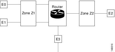
The following describe the relationships between the interfaces and security zones shown in the above figure.
-
Interfaces E0 and E1 are members of the security zone Z1.
-
Interface E2 is a member of the security zone Z2.
-
Interface E3 is not a member of any of the security zone.
In this scenario, the following situations exist:
-
Traffic flows freely between interfaces E0 and E1 because they are members of the same security zone (Z1).
-
If no policies are configured, traffic will not flow between zones (for example, E0 and E2, E1 and E2, E3 and E1, and E3 and E2).
-
Traffic can flow between interface E0 or E1 and E2 only when an explicit policy is configured to permit the traffic between zone Z1 and zone Z2.
Traffic can never flow between E3 and interface E0, E1or E2 because E3 is not a part of any security zone.
Cisco Prime Infrastructure supports the zone-based firewall feature on Cisco ASR, ISR, and CSR routers. Using Cisco Prime Infrastructure, you can configure a zone-based firewall policy template and deploy it to multiple devices. After you deploy the zone-based configuration, you can navigate to the Device Work Center to view the deployed firewall configuration on a specific device.
To monitor the zone-based firewall, check the Zone-Based Firewall Monitor Hits capability on the Device Work Center or the Cisco Prime Infrastructure syslog feature, which supports zone-based firewall syslog messages.
Cisco Prime Infrastructure can configure Zone-Based Firewall either through CLI (over Telnet or SSH) or through WSMA. Zone-Based Firewall can be configured through WSMA in a more efficient and robust method and we recommend that you use the WSMA protocols for configuring Zone-Based Firewall. For more information on using WSMA with Cisco Prime Infrastructure, see Set Up Devices to Use AVC Features with WSMA.
Configure a Zone-Based Firewall: Workflow
To configure a zone-based firewall on more than one device, use a zone-based template to make the changes. For zone-based firewall templates, you must first design the zone-based firewall in the network by defining the zones in the network. In Cisco Prime Infrastructure, zones are represented by interface role global object, which dynamically selects the list of interfaces that belong to the zone. Next, define and create network objects in the firewall environment. The Zone-based firewall feature supports only IPv4 network in Cisco Prime Infrastructure. (IPv6 is not supported.)
Note |
The Zone-Based Firewall feature is supported on the following: ASR platform from Cisco IOS-XE Release 15.2(2)S or later, ISR G2 platform from Cisco IOS Release 15.0(1)M or later, ISR G3 platform from Cisco IOS-XE 15.3(2)S Release or later, CSR platform from Cisco IOS-XE 15.3(1)S Release or later, Cisco ISRv platform from Cisco IOS-XE Release 16.3 or later, and Cisco ISR 1000 platform from Cisco IOS-XE Release 16.6.1 or later. |
To configure a zone-based firewall template:
- Define the zones. A security zone is defined as an interface role.
- Define the IPv4 network
objects.
Note
Cisco Prime Infrastructure 2.0 supports only IPv4 network objects.
- Design a firewall policy and deploy it to multiple devices (for more information, see Create a Policy Rule for a Single Device's Zone-Based Firewall ).
- Validate the configuration for a specific device (see Control Firewall Policies Between Groups of Interfaces using Zone-Based Firewalls ).
- Modify the global objects and template configuration (see Configure the Policy Rules for a Zone-Based Firewall ).
- Monitor the policy rules (see Monitor and Troubleshoot Policy Rules for a Single Devices Zone Based Firewall ).
- Monitor the syslog messages.
To modify security zones, IPv4 network objects, and firewall policies, edit the firewall policy and redeploy it to the relevant devices.
Configure the Policy Rules for a Zone-Based Firewall
After you create a shared policy objects, create a zone-based firewall policy rules template.
To create a Zone-Based Firewall Policy Rules template, follow these steps:
Procedure
| Step 1 |
Choose Configuration > Templates > Features & Technologies > Security > Zone Based Firewall > Policy Rules. |
| Step 2 |
In the Template Basic area, enter a name and a description in the appropriate fields. |
| Step 3 |
In the Validation Criteria area, choose a Device Type from the list and enter the OS Version. |
| Step 4 |
Enter the required fields. For descriptions of the template parameters, see the Cisco Prime Infrastructure Reference Guide. |
| Step 5 |
Click Save as New Template. |
Remove the Zone-based Firewall Configuration Using CLI Templates
Users can remove the zone-based firewall configuration from the devices using the CLI templates by performing the steps provided below:
Procedure
| Step 1 |
Navigate to Configuration > Templates > Features & Technologies. |
| Step 2 |
Expand the CLI Templates tree and select the System Template-CLI option. |
| Step 3 |
Select the Delete_ZBFW_Configuration template. |
| Step 4 |
You must sync-up the devices for which you wish to remove the zone-based firewall configuration and then click the Deploy button. |
| Step 5 |
Select a devices from which you wish to remove the zone-based firewall configuration. |
| Step 6 |
You must sync-up the devices again to ensure the zone-based firewall configuration is removed.. |
Configuring the Policy Rules for a Zone-Based Firewall on Single Devices
To configure a zone-based firewall on a single device, use Device Work Center zone-based configuration to make the changes.
Create a Security Zone for a Single Device's Zone-Based Firewall
To create a security zone, follow these steps:
Note |
The Zone Based Firewall feature is supported on the ASR platform on Cisco IOS-XE Release 15.2 (2)S or later, ISR G2 platform on Cisco IOS release 15.0 (1) M or later, ISR G3 platform on Cisco IOS-XE Release 15.3(2)S or later, and CSR platform on Cisco IOS-XE Release 15.3(1)S. |
Before you begin
Procedure
| Step 1 |
Choose , then click on the device. |
||
| Step 2 |
In the Configuration tab, expand the Security subfolder. |
||
| Step 3 |
In the Security subfolder, expand the Zone Based Firewall > Common Building Blocks, then click Zones. |
||
| Step 4 |
Click Add Zone to create the security zone. |
||
| Step 5 |
Select a Zone Name. |
||
| Step 6 |
(Cisco ASR devices only) To make this the default zone for Cisco ASR devices, click Enable Default. The default zone will host all of the interfaces that are not related to any zone. |
||
| Step 7 |
Click OK to save the configuration. |
||
| Step 8 |
Select the VRF of the zone.
|
||
| Step 9 |
To assign the interfaces to the security zone, click the down arrow icon. The Interface Object Selector dialog box appears.
|
||
| Step 10 |
In the Advanced options column, click Configure. The Advanced Parameters Configuration dialog box appears. |
||
| Step 11 |
Define a set of advanced parameters which would be applicable for the inspected traffic that goes through the interfaces that belongs to the zone. For each parameter, select the check box to the left of the parameter name to override the default value for the parameter and then select the new value for the parameter. (Optional) In the Advanced Parameters Configuration dialog box, do the following:
|
||
| Step 12 |
Click:
|
||
| Step 13 |
To edit the existing security zone parameters, select the zone, and click Edit in the Advance options column. The Advanced Parameters Configuration dialog box appears. |
||
| Step 14 |
In the Advanced Parameters Configuration dialog box, edit the values and click Save to save the changes. When you hover your mouse over the Advanced Options icon, the configured parameters will be displayed in the quick view window. |
||
| Step 15 |
Enter the description for the zone, then click Save. |
Create a Policy Rule for a Single Device's Zone-Based Firewall
To create a policy rule, follow these steps:
Procedure
| Step 1 |
Choose Inventory > Device Management > Network Devices, then select a device. |
||
| Step 2 |
In the Feature Configuration pane, expand the Security subfolder. |
||
| Step 3 |
In the Security subfolder, expand the Zone Based Firewall and then click Policy Rules. The Policy Rules page appears. |
||
| Step 4 |
To edit an existing policy rule, choose one of the following options:
|
||
| Step 5 |
From the Policy Rules page, click Add Rule and complete the fields. When you add a rule, you can place a rule at the top or bottom of the policy or after/before an existing rule. Firewall Rules are processed according to their order. To control the order of the rules, select the location of the rule in the table and use Add Top or Add Bottom option to add the rule to the top or the bottom of the table. Select a rule and use Add After or Add Before option to add the rule before or after an existing rule.You can place a rule at any given location and later use drag and drop to change its location. |
||
| Step 6 |
(Optional) Enter the firewall rule name. If you do not provide the name for the firewall rule, the system generates a name for the firewall rule. You cannot use these formats rule_<number> or EMS_rule_<number> to create the firewall rule name (For example, rule_1). These are system reserved formats. |
||
| Step 7 |
Select the source and destination zones for the rule, the rule is applicable only for traffic that flows from the source zone to the destination zone. Note that the source and destination zones must be different. |
||
| Step 8 |
To add the source and the destination IP address, click the add icon. The Source/Destination IP address dialog box appears.
|
||
| Step 9 |
(Optional) Set the Service values. To add or remove the service, click the down arrow icon. The Firewall Service dialog box appears. You can also select a predefined Service. For creating services, see Create a Service Group for a Single Device's Zone-Based Firewall.
|
||
| Step 10 |
Select the appropriate action. The options are: Drop, Drop and Log, Inspect, Pass, and Pass and Log. |
||
| Step 11 |
If you select the action to inspect, click Configure in the Advance options column. The Advanced Parameters Configuration dialog box appears. |
||
| Step 12 |
In the Advanced Parameters Configuration dialog box, do the following: |
||
| Step 13 |
Click Save to apply the rule to the device. For description of the elements, see the Cisco Prime Infrastructure Reference Guide. |
Monitor and Troubleshoot Policy Rules for a Single Devices Zone Based Firewall
The monitoring feature allows you to monitor policy rules. You can identify the most-used rules, and you can troubleshoot a specific rule and verify hits for the selected rule.
To monitor policy rules, follow these steps:
Procedure
| Step 1 |
Choose Inventroy > Device Management > Network Devices, then select a device. |
||
| Step 2 |
In the Feature Configuration pane, expand the Security folder. |
||
| Step 3 |
In the Security subfolder, expand the Zone Based Firewall and then click Policy Rules. The Firewall Rules Page appears. |
||
| Step 4 |
In the Firewall Rules page, click Hit Counters and use the one of the following options to analyze the sessions and packets hit counters for the firewall rules. |
||
| Step 5 |
Click the Show All option to view the packets and sessions counters for the firewall rules. The packets and sessions counters are displayed in two separate columns.
|
||
| Step 6 |
To know the time of last update for the rules, hover the mouse cursor over the column names or click the Last Update Time option in the Hit Counters. |
||
| Step 7 |
Click the Show for selected rules option to show the hit counters for a specific rule or a couple of selected rules. The hit counters would be displayed in a popup dialog box with the refresh button which allows the quick refresh of the data. |
||
| Step 8 |
Use the predefined filters options available in the top-right corner of the table to display the rules at the top or bottom based on the packets/sessions counts. |
||
| Step 9 |
Click Reset All Counters to discard all of the rules counters on the device. The application will display a warning message before resetting the rules counters. |
Create a Service Group for a Single Device's Zone-Based Firewall
You can create, update or delete a service groups. Service group provides an option to group together several port-based applications to logical groups which could be used in firewall policies.
For example, you can define a browsing service-group object and assign both HTTP and HTTPS applications to it. Then you can use this browsing service-group in firewall rules to permit or deny browsing traffic, rather than selecting both HTTP and HTTPS in those rules.
To create a service group, follow these steps:
Procedure
| Step 1 |
Choose Inventory > Device Management > Network Devices, then select a device. |
| Step 2 |
In the Feature Configuration pane, expand the Security subfolder. |
| Step 3 |
In the Security subfolder, expand the Zone Based Firewall > Common Building Blocks, and then click Service Groups. The Service Groups page appears. |
| Step 4 |
To create the Service Group:
|
| Step 5 |
To edit an existing Service Group, do one of the following:
|
| Step 6 |
Click Save to apply your changes to the device. |
Assign Application TCP/UDP Ports for a Single Device's Zone-Based Firewall
You can assign or unassign the Transmission Control Protocol (TCP) / User Datagram Protocol (UDP) ports to an application.
Note |
When you click Save in the following procedure, your changes are deployed on the device. You cannot review the requested operation or remove the request from the pending changes queue. |
To assign or unassign TCP/UDP ports for an application, follow these steps:
SUMMARY STEPS
- Choose Inventory > Device Management > Network Devices, then select a device.
- In the Feature Configuration pane, expand the Security subfolder.
- In the Security subfolder, expand the Zone Based Firewall > Common Building Blocks, and then click Port Mappings. The Port Application Mapping page appears.
- To assign or unassign the TCP/UDP ports to an application, click the application and update its TCP/UDP ports value. The TCP/UDP Port values are assigned to the specific application.
- Click Save to save the configurations.
DETAILED STEPS
| Step 1 |
Choose Inventory > Device Management > Network Devices, then select a device. |
||
| Step 2 |
In the Feature Configuration pane, expand the Security subfolder. |
||
| Step 3 |
In the Security subfolder, expand the Zone Based Firewall > Common Building Blocks, and then click Port Mappings. The Port Application Mapping page appears.
|
||
| Step 4 |
To assign or unassign the TCP/UDP ports to an application, click the application and update its TCP/UDP ports value. The TCP/UDP Port values are assigned to the specific application.
|
||
| Step 5 |
Click Save to save the configurations. |
Configure Default Parameters for a Single Cisco ISR Device's Zone-Based Firewall
To configure a default parameters, follow these steps:
Procedure
| Step 1 |
Choose Inventory > Device Management > Network Devices, then select a device. |
||
| Step 2 |
In the Feature Configuration pane, expand the Security subfolder. |
||
| Step 3 |
In the Security subfolder, expand the Zone Based Firewall and then click Default Parameters. The Default Parameters page appears. |
||
| Step 4 |
In the Default Parameters page, change the parameters value.
|
||
| Step 5 |
Click Save to save the configuration. |
Assign an Interface to a Different Zone in a Single Device's Zone-Based Firewall
The interfaces view gives an overview of the interfaces on the device which are applicable for firewall inspection. The view allows viewing and modifying the assignment of those interfaces to security zones.
To assign or unassign an interface for a zone, follow these steps:
Procedure
| Step 1 |
Choose Inventory > Device Management > Network Devices, then select a device. |
| Step 2 |
In the Feature Configuration pane, expand the Security subfolder. |
| Step 3 |
In the Security subfolder, expand the Zone Based Firewall and then click Interfaces. |
| Step 4 |
In the Interface page, select the interface that you want to change and click the down arrow icon. The Zone dialog box appears. |
| Step 5 |
In the Zone dialog box, select the new security zone for the interface. If the selected interface is already assigned to a zone, you will get a warning message. |
| Step 6 |
Click Yes on the warning message if you want to change the assignment of that interface. |
| Step 7 |
To un-assign the interface from the specific zone, select the interface and delete the zone information. |
| Step 8 |
Click Save to save and apply your changes. |
How to Transition Between the CLI User Interfaces in Prime Infrastructure
The following figure illustrates how to transition between the Prime Infrastructure and Linux CLI user interfaces on deployments running Prime Infrastructure.

Add NAM Application Servers as Data Sources
Prime Infrastructure supports various features to be configured on NAM, remotely. The NAM Application Servers feature enables you to configure the NAM device with Application servers.
To Configure the parameters of the Application servers, with NAM device, follow these steps:
Procedure
| Step 1 |
Choose Inventory > Device Management > Network Devices, then select a device. |
| Step 2 |
Click Add. |
| Step 3 |
Enter the IP address of the server in Add Servers dialog box and click Add button inside the dialog box. The list of server IPaddresses are displayed under IP address column. |
| Step 4 |
Select the IP addresses of the servers to be deployed to the NAM device, then Click Add to NAM Server lists. |
| Step 5 |
Select the IP Address of one or more of the NAM devices in the Add Server(s) to NAM Server Lis dialog box, and click Add button within the dialog box. The selected device IP addresses are displayed under Part of NAM Server List on column, and the server parameters get configured on the selected NAM devices. |
 Feedback