- Monitoring Dashlets and Dashboards
- Monitoring Jobs
- Configure Monitoring Settings
- What is the Device Work Center?
- Configuring Features on a Device
- Application Visibility
- Overview of NAT
Operating and Monitoring the Network
Under the Operate tab, Prime NCS (WAN) provides tools to help you monitor your network on a daily basis, as well as perform other day-to-day or ad hoc operations relating to network device inventory and configuration management. The Operate tab contains dashboards, the Device Work Center, and the tools you need for day-to-day monitoring, troubleshooting, maintenance, and operations.
Monitoring Dashlets and Dashboards
Prime NCS (WAN) automatically displays monitoring data in dashboards and dashlets. You can choose one of the following dashboards under Operate > Monitoring Dashboard to view summary information:
•![]() Overview—Displays overview information about your network such as device counts, and the top 5 devices by CPU and memory utilization. From the overview dashboard, you can click on device or interface alarms counts to view detailed dashboards and alarms and events in order to help troubleshoot and isolate issues.
Overview—Displays overview information about your network such as device counts, and the top 5 devices by CPU and memory utilization. From the overview dashboard, you can click on device or interface alarms counts to view detailed dashboards and alarms and events in order to help troubleshoot and isolate issues.
•![]() Incidents—Displays a summary of alarms and events for your entire network, for a particular site, or for a particular device. By clicking on an item in the dashboard, you can view details about the alarm or event and troubleshoot the problem.
Incidents—Displays a summary of alarms and events for your entire network, for a particular site, or for a particular device. By clicking on an item in the dashboard, you can view details about the alarm or event and troubleshoot the problem.
•![]() Performance—Displays CPU and memory utilization information.
Performance—Displays CPU and memory utilization information.
•![]() Detail Dashboards—Displays network health summaries for sites, devices, or interfaces. The detailed dashboards allow you to see congestion in your network and gather detailed site, device, and interface information. For example, you can view detailed dashboards for a particular site to determine which devices have the most alarms, device reachability status for the site, etc.
Detail Dashboards—Displays network health summaries for sites, devices, or interfaces. The detailed dashboards allow you to see congestion in your network and gather detailed site, device, and interface information. For example, you can view detailed dashboards for a particular site to determine which devices have the most alarms, device reachability status for the site, etc.
You can change the information displayed in the dashboards as explained in Common Tasks For Dashboards.
Table 6-1 describes where to find monitoring information in the Prime NCS (WAN) dashboards.
Monitoring Jobs
Choose Tools > Task Manager > Jobs Dashboard to view the status of jobs and to:
•![]() View all running and completed jobs and corresponding job details
View all running and completed jobs and corresponding job details
•![]() Filter jobs to view the specific jobs for which you are interested
Filter jobs to view the specific jobs for which you are interested
•![]() View details of the most recently submitted job
View details of the most recently submitted job
•![]() View job execution results
View job execution results
•![]() Modify jobs including deleting, editing, running, canceling, pausing, and resuming jobs
Modify jobs including deleting, editing, running, canceling, pausing, and resuming jobs
If a job fails, you can get troubleshooting information from the Jobs Dashboard. When you expand a job to view its details, click the History tab, and rest your cursor over the Status field. The results window displays troubleshooting information that can help you determine why the job failed.
Configure Monitoring Settings
You can define how Prime NCS (WAN) monitors the devices and interfaces in your network.
By enabling the Auto Monitoring option, you can have Prime NCS (WAN) monitor the availability, CPU, memory and temperature of all your network devices automatically. By default, Prime NCS (WAN) polls all devices in your network every 15 minutes for device-health data. Most users will want to enable Auto Monitoring.
You may want to avoid enabling Auto Monitoring if you have a very large network or Prime NCS (WAN) deployment, to avoid excessive polling traffic. In this case, you can leave Auto Monitoring disabled, and create one or more device groups containing your business-critical devices only. You may also want to create a version of the default device health monitoring template with a polling frequency appropriate for these devices. When you deploy the default or custom device health monitoring template, you can select to apply it to your business-critical device group only.
You can also enable deduplication, if applicable, for Cisco IOS Netflow and Cisco Prime Assurance. If you have multiple routers and switches that send netflow to the Cisco Prime Assurance server and multiple NAMs that Cisco Prime Assurance retrieves data from, Cisco Prime Assurance could receive the same traffic statistic more than once. You can enable deduplication so that Cisco Prime Assurance doesn't count the same metrics more than once.
Step 1 ![]() Choose Administration > System, then select Monitoring Settings.
Choose Administration > System, then select Monitoring Settings.
Step 2 ![]() Check the following options:
Check the following options:
•![]() Auto monitoring to have Prime NCS (WAN) monitor all devices and interfaces automatically.
Auto monitoring to have Prime NCS (WAN) monitor all devices and interfaces automatically.
•![]() Enable deduplication to have Prime NCS (WAN) eliminate redundant data.
Enable deduplication to have Prime NCS (WAN) eliminate redundant data.
What is the Device Work Center?
From Operate > Device Work Center, you can view the device inventory and device configuration information. The Device Work Center contains general administrative functions at the top and configuration functions at the bottom as described in Table 6-2.
|
|
|
|
|---|---|---|
Manage devices |
Add, edit, bulk import, and delete devices, and force data collection from devices. |
Buttons located at the top of the Device Work Center. |
View basic device information and collection status |
View basic device information such as reachability status, IP address, device type, and collection status information. |
Displayed in the top portion of the Device Work Center. Rest your cursor on the Collection Status cell and click on the icon to view errors related to the inventory collection. |
Manage device groups |
By default, Prime NCS (WAN) creates dynamic device groups and assigns devices to the appropriate Device Type folder. You can create new device groups that appear under the User Defined folder. |
Displayed on the left pane of the Device Work Center. See Using Device Groups for more information about creating and using device groups. |
Add devices to sites |
After you set up a site profile, you can add devices to the site. Note |
Add to Site button located at the top of the Device Work Center. See Creating Site Profiles for more information about adding devices to sites. |
View device details |
View device details such as memory, port, environment, and interface information. |
Choose a device in the Device Work Center, then click the Device Details tab at the bottom of the screen. |
View device information, status, and associated modules, alarms, neighbors, and interfaces. See Using 360° View for more information. |
Rest your cursor on a device IP address and click the icon that appears. |
|
Create and deploy configuration templates |
You can create and deploy configuration templates for the selected device. You can also preview the CLI that will be deployed to the device. |
Click the Configuration tab at the bottom of the Device Work Center. |
View device configurations |
View archived configurations, schedule configuration rollbacks, and schedule archive collections. |
Click the Configuration Archive tab at the bottom of the Device Work Center. |
View software images |
View details about the image on the selected device, the recommended software image for the device, and the latest software image operations for a device. |
Click the Image tab at the bottom of the Device Work Center. |
Configuring Features on a Device
You can create or change the feature configuration for the selected device. The following topics provide more information:
Application Visibility
The Application Visibility (AV) feature helps in monitoring the traffic sent towards the internet. To configure AV, you need to perform the following:
•![]() Create AV Configuration
Create AV Configuration
•![]() Assign AV policies on interfaces
Assign AV policies on interfaces
•![]() Change AV Advanced options
Change AV Advanced options

Note ![]() The Application Visibility feature is supported on ASR devices from the IOS version 3.5 or later. This feature is not supported on ISR devices. If you make any changes via CLI interface on objects/entities that starts with "EMS_" is unsupported and may cause unexpected behavior.
The Application Visibility feature is supported on ASR devices from the IOS version 3.5 or later. This feature is not supported on ISR devices. If you make any changes via CLI interface on objects/entities that starts with "EMS_" is unsupported and may cause unexpected behavior.
Configuring AV
The Application Visibility Configuration feature creates the required elements in the device to send the NetFlow messages for Transaction Records and Usage Records. To configure AV, follow these steps.
Step 1 ![]() Choose Operate > Device Work Center.
Choose Operate > Device Work Center.
Step 2 ![]() Choose the device from the list or click Add to create a new device, then configure the device.
Choose the device from the list or click Add to create a new device, then configure the device.
Step 3 ![]() After selecting the device, click Configuration. The Feature Selector panel appears.
After selecting the device, click Configuration. The Feature Selector panel appears.
Step 4 ![]() From the Feature Selector panel, choose Application Visibility > Configuration. The AV Configuration page appears.
From the Feature Selector panel, choose Application Visibility > Configuration. The AV Configuration page appears.
Step 5 ![]() From the AV Configuration page, set the Primary CM IP Address, Secondary CM IP Address, VPN Routing and Forwarding (VRF), and Source IP address.
From the AV Configuration page, set the Primary CM IP Address, Secondary CM IP Address, VPN Routing and Forwarding (VRF), and Source IP address.
Step 6 ![]() Set the advanced AV parameters. For more information on the Advanced AV parameters, see Changing AV Advanced Options.
Set the advanced AV parameters. For more information on the Advanced AV parameters, see Changing AV Advanced Options.
Table 6-3 lists the elements on the AV Configuration page.
Step 7 ![]() Click Save/ Apply to save the changes in the server.
Click Save/ Apply to save the changes in the server.
Managing Interface
To edit the existing AV policy, follow these steps.
Step 1 ![]() Choose Operate > Device Work Center.
Choose Operate > Device Work Center.
Step 2 ![]() Choose the device from the list or click Add to create a new device, then configure the device.
Choose the device from the list or click Add to create a new device, then configure the device.
Step 3 ![]() After selecting the device, click Configuration. The Feature Selector panel appears.
After selecting the device, click Configuration. The Feature Selector panel appears.
Step 4 ![]() From the Feature Selector panel, choose Application Visibility > Interfaces.
From the Feature Selector panel, choose Application Visibility > Interfaces.
Step 5 ![]() In the Interface page, select one or more interfaces to Enable/Disable AV Records. To enable the AV on the interface, select "Enable", and then select the record to which you want to send the collector.
In the Interface page, select one or more interfaces to Enable/Disable AV Records. To enable the AV on the interface, select "Enable", and then select the record to which you want to send the collector.
a. ![]() Usage Records (UR)—Usage Records are records of the different type of applications that run on a specific interface. The operator can use the Usage Records to monitor the bandwidth usage of different applications. The Usage Records can show the application usage over a specific time period, the peak and average usages, and usage for a specific application type. Usage Records perform periodic aggregation of the category information for the interface. (For example, export information for peer-to-peer traffic or email usage).
Usage Records (UR)—Usage Records are records of the different type of applications that run on a specific interface. The operator can use the Usage Records to monitor the bandwidth usage of different applications. The Usage Records can show the application usage over a specific time period, the peak and average usages, and usage for a specific application type. Usage Records perform periodic aggregation of the category information for the interface. (For example, export information for peer-to-peer traffic or email usage).
b. ![]() Transaction Records (TR)—A transaction is a set of logical exchanges between endpoints. There is normally one transaction within a flow. The Transaction Record monitors the traffic at transaction levels. These records provide a detailed analysis of the traffic flows. Transaction Records are bound to the input and output directions of the network side interfaces. These Transaction Records allow the system to capture each unidirectional flow once.
Transaction Records (TR)—A transaction is a set of logical exchanges between endpoints. There is normally one transaction within a flow. The Transaction Record monitors the traffic at transaction levels. These records provide a detailed analysis of the traffic flows. Transaction Records are bound to the input and output directions of the network side interfaces. These Transaction Records allow the system to capture each unidirectional flow once.
Step 6 ![]() Click OK to deploy the changes to the device.
Click OK to deploy the changes to the device.
Changing AV Advanced Options
To change the Application Visibility Advanced options, follow these steps.
Step 1 ![]() Choose Operate > Device Work Center.
Choose Operate > Device Work Center.
Step 2 ![]() Select the device from the list or click Add to create a new device, then configure the device.
Select the device from the list or click Add to create a new device, then configure the device.
Step 3 ![]() After selecting the device, click Configuration. The Feature Selector panel appears.
After selecting the device, click Configuration. The Feature Selector panel appears.
Step 4 ![]() From the Feature Selector panel, choose Application Visibility > Configuration. The AV Configuration page appears.
From the Feature Selector panel, choose Application Visibility > Configuration. The AV Configuration page appears.
Step 5 ![]() In the AV Configuration page, set the new values for the AV configuration.
In the AV Configuration page, set the new values for the AV configuration.
Step 6 ![]() Click on the title area to view the Advanced Options and Record Advanced Options. To customize the value, check the specific attribute check box and set the new value. To use the system default value, uncheck the check box of the specific attribute.
Click on the title area to view the Advanced Options and Record Advanced Options. To customize the value, check the specific attribute check box and set the new value. To use the system default value, uncheck the check box of the specific attribute.
Step 7 ![]() Click Save / Apply to save the changes in the server.
Click Save / Apply to save the changes in the server.
Table 6-4 lists the elements on the AV Configuration page.
Overview of NAT
The Network Address Translation (NAT) is the process where a network device, usually a firewall, assigns a public address to a computer (or group of computers) inside a private network. The NAT helps to limit the number of public IP addresses used by an organization or company, for both economy and security purposes.
The NAT feature allows organizations to resolve the problem of IP address depletion when they have existing networks and need to access the Internet. The NAT allows the IP network of an organization to use different IP address space for the outside network. Thus, NAT allows an organization that does not have globally routable addresses to connect to the Internet by translating those addresses into globally routable address space. The NAT also allows a more graceful renumbering strategy for organizations that are changing service providers or voluntarily renumbering into Classless Inter Domain Routing (CIDR) blocks. The NAT is described in RFC 1631.
A router configured with the NAT will have at least one interface to the inside network and one to the outside network. In a typical environment, the NAT is configured at the exit router between a sub domain and a backbone. When a packet leaves the domain, the NAT translates the locally significant source address into a globally unique address. When a packet enters the domain, the NAT translates the globally unique destination address into a local address. If more than one exit point exists, each NAT must have the same translation table. If the NAT cannot allocate an address because it has run out of addresses, it drops the packet and sends an Internet Control Message Protocol (ICMP) host unreachable packet.
For more information on NAT, see http://www.cisco.com/en/US/docs/ios-xml/ios/ipaddr_nat/configuration/xe-3s/iadnat-addr-consv.html.
Types of NAT
The NAT operates on a router—Generally connecting only two networks together—and translates your private (inside local) addresses within the internal network, into public (inside global) addresses before any packets are forwarded to another network. This functionality gives you the option to configure the NAT so that it will advertise only a single address for your entire network to the outside world. Doing this effectively hides the internal network from the world, giving you some additional security.
NAT types include:
•![]() Static Address Translation (SAT) —Allows one-to-one mapping between local and global addresses.
Static Address Translation (SAT) —Allows one-to-one mapping between local and global addresses.
•![]() Dynamic Address Translation—Maps unregistered IP addresses to registered IP addresses of out of a pool of registered IP addresses.
Dynamic Address Translation—Maps unregistered IP addresses to registered IP addresses of out of a pool of registered IP addresses.
•![]() Overloading—A form of dynamic NAT that maps multiple unregistered IP addresses to a single registered IP address (many to one) using different ports. This method is also known as Port Address Translation (PAT). By using PAT (NAT Overload), thousands of users can be connected to the Internet using only one real global IP address.
Overloading—A form of dynamic NAT that maps multiple unregistered IP addresses to a single registered IP address (many to one) using different ports. This method is also known as Port Address Translation (PAT). By using PAT (NAT Overload), thousands of users can be connected to the Internet using only one real global IP address.
How to Configure NAT for IP Address Conservation
To configure NAT, perform the following steps:
1. ![]() Create the NAT pool (required for Dynamic NAT)
Create the NAT pool (required for Dynamic NAT)
2. ![]() Configure the ACL
Configure the ACL
3. ![]() Create the NAT44 rules
Create the NAT44 rules
4. ![]() Assign rules on the interfaces
Assign rules on the interfaces
5. ![]() Set up the NAT maximum translation (Optional)
Set up the NAT maximum translation (Optional)
Note ![]() The NAT feature is supported on ASR platform from the IOS version 3.5 or later. The NAT feature is supported on ISR platform from the IOS version 12.4(24)T or later. If you make any changes via CLI interface on objects/entities that starts with "EMS_" is unsupported and may cause unexpected behavior.
The NAT feature is supported on ASR platform from the IOS version 3.5 or later. The NAT feature is supported on ISR platform from the IOS version 12.4(24)T or later. If you make any changes via CLI interface on objects/entities that starts with "EMS_" is unsupported and may cause unexpected behavior.
IP Pools
The IP Pool is a device object that represents IP ranges to be used on the Dynamic NAT. The NAT IP Pools feature allows you to create a new pool that can be used in the Dynamic NAT, change existing the pool, and delete the pool from the device.
Creating, Editing, and Deleting IP Pools
To create, edit, and delete the IP Pools, follow these steps.
Step 1 ![]() Choose Operate > Device Work Center.
Choose Operate > Device Work Center.
Step 2 ![]() Select the device from the list or click Add to create a new device, then configure the device.
Select the device from the list or click Add to create a new device, then configure the device.
Step 3 ![]() After selecting the device, click Configuration. The Feature Selector panel appears.
After selecting the device, click Configuration. The Feature Selector panel appears.
Step 4 ![]() From the Feature Selector panel, choose NAT > IP Pools. The NAT Pools page appears.
From the Feature Selector panel, choose NAT > IP Pools. The NAT Pools page appears.
Step 5 ![]() From this page, click the Add IP Pool > IP+Prefix or IP Range + Prefix button, and enter the Name, IP Address/Range, Prefix Length, and Description.
From this page, click the Add IP Pool > IP+Prefix or IP Range + Prefix button, and enter the Name, IP Address/Range, Prefix Length, and Description.
Step 6 ![]() Click Ok to save the configurations.
Click Ok to save the configurations.
Table 6-5 lists the elements on the IP Pools page.
Step 7 ![]() Click the Apply button to deploy the pool to the server data base.
Click the Apply button to deploy the pool to the server data base.
Step 8 ![]() To edit the existing IP Pool, in the NAT IP Pools page do the following:
To edit the existing IP Pool, in the NAT IP Pools page do the following:
a. ![]() Click on the selected IP Pools parameters row, and edit the parameters. or
Click on the selected IP Pools parameters row, and edit the parameters. or
b. ![]() Select the IP Pools, and click the Edit button. The selected IP Pools entity opens for editing. You can edit all the parameters except the pool name.
Select the IP Pools, and click the Edit button. The selected IP Pools entity opens for editing. You can edit all the parameters except the pool name.
Step 9 ![]() Click Save / Apply to save the changes in the server.
Click Save / Apply to save the changes in the server.
Step 10 ![]() To delete the existing IP Pools, select the IP Pool, and then click the Delete button.
To delete the existing IP Pools, select the IP Pool, and then click the Delete button.
Step 11 ![]() Click Ok on the warning message to delete the IP Pool. The selected IP Pool will be deleted.
Click Ok on the warning message to delete the IP Pool. The selected IP Pool will be deleted.
NAT44
The NAT44 feature allows the user to create, delete, and change the NAT44 rules.
Creating, Editing, and Deleting NAT44 Rule
This section describes how to create the NAT44 rules.
There are three types of NAT rules:
•![]() Static
Static
•![]() Dynamic
Dynamic
•![]() Dynamic PAT
Dynamic PAT
To create the NAT44 rule, follow these steps.
Step 1 ![]() Choose Operate > Device Work Center.
Choose Operate > Device Work Center.
Step 2 ![]() Select the device from the list or click Add to create a new device, then configure the device.
Select the device from the list or click Add to create a new device, then configure the device.
Step 3 ![]() After selecting the device, click Configuration. The Feature Selector panel appears.
After selecting the device, click Configuration. The Feature Selector panel appears.
Step 4 ![]() From the Feature Selector left panel, choose NAT > NAT44.
From the Feature Selector left panel, choose NAT > NAT44.
Step 5 ![]() From the NAT 44 Rule page, click the down arrow icon on the Add NAT Rule button.
From the NAT 44 Rule page, click the down arrow icon on the Add NAT Rule button.
•![]() Click Static to create Static Rule. For elements on this page, see Table 6-6.
Click Static to create Static Rule. For elements on this page, see Table 6-6.
•![]() Click Dynamic to create Dynamic NAT Rule. For elements on this page, see Table 6-7.
Click Dynamic to create Dynamic NAT Rule. For elements on this page, see Table 6-7.
•![]() Click Dynamic PAT to create Dynamic PAT Rule. For elements on this page, see Table 6-8.
Click Dynamic PAT to create Dynamic PAT Rule. For elements on this page, see Table 6-8.
Table 6-6 lists the elements on the Static Rule page.
Table 6-7 lists the elements on the Dynamic NAT page.
Table 6-8 lists the elements on the Dynamic PAT page.
Step 6 ![]() Click:
Click:
•![]() Save to save and deploy the changes to the device.
Save to save and deploy the changes to the device.
•![]() Cancel to exit without saving.
Cancel to exit without saving.
Step 7 ![]() To edit the existing NAT44 rule, in the NAT44 page, do the following:
To edit the existing NAT44 rule, in the NAT44 page, do the following:
a. ![]() Click on the selected NAT44 rules parameters row, and edit the parameters. or
Click on the selected NAT44 rules parameters row, and edit the parameters. or
b. ![]() Select the NAT44 rule, and click the Edit button. The selected NAT44 rule entity opens for editing. You can edit all the parameters except the pool Name.
Select the NAT44 rule, and click the Edit button. The selected NAT44 rule entity opens for editing. You can edit all the parameters except the pool Name.
Step 8 ![]() You can change the Source and Destination according to the creation rules. You can also change the Options selection according to the creation rules.
You can change the Source and Destination according to the creation rules. You can also change the Options selection according to the creation rules.
Step 9 ![]() Click Save/ Apply to save the changes in the server.
Click Save/ Apply to save the changes in the server.
Step 10 ![]() To delete the existing NAT44 rules, select the rules, and then click the Delete button.
To delete the existing NAT44 rules, select the rules, and then click the Delete button.
Step 11 ![]() Click Ok on the warning message to delete the rules. The selected NAT44 rules will be deleted.
Click Ok on the warning message to delete the rules. The selected NAT44 rules will be deleted.
Managing Interfaces
A virtual interface is a logical interface configured with generic configuration information for a specific purpose or for configuration common to specific users, plus router-dependent information.
Configuring Interfaces
To assign the interfaces to a specific association, follow these steps.
Step 1 ![]() Choose Operate > Device Work Center.
Choose Operate > Device Work Center.
Step 2 ![]() Select the device from the list or click Add to create a new device, then configure the device.
Select the device from the list or click Add to create a new device, then configure the device.
Step 3 ![]() After selecting the device, click Configuration. The Feature Selector panel appears.
After selecting the device, click Configuration. The Feature Selector panel appears.
Step 4 ![]() From the Feature Selector left panel, choose NAT > Interfaces.
From the Feature Selector left panel, choose NAT > Interfaces.
Step 5 ![]() In the Interface page, select the interface you want to change and enter the VRF and select the association from the drop-down list.
In the Interface page, select the interface you want to change and enter the VRF and select the association from the drop-down list.
Table 6-9 lists the elements on the Interfaces page.
Step 6 ![]() Click:
Click:
•![]() Save/ Apply to save the changes in the server.
Save/ Apply to save the changes in the server.
•![]() Cancel to exit without saving.
Cancel to exit without saving.
Managing NAT MAX Translation
The Rate Limiting NAT Translation feature provides the ability to limit the maximum number of concurrent NAT operations on a router. In addition, the NAT MAX feature gives more control to the users to use the NAT addresses. The Rate Limiting NAT Translation feature can be used to limit the effects of viruses, worms, and denial-of-service attacks.
The NAT Maximum Translations feature allows you to reset the global translation attribute values.
Setting NAT MAX Translation
To set the MAX Translation, follow these steps.
Step 1 ![]() Choose Operate > Device Work Center.
Choose Operate > Device Work Center.
Step 2 ![]() Select the device from the list or click Add to create a new device, then configure the device.
Select the device from the list or click Add to create a new device, then configure the device.
Step 3 ![]() After selecting the device, click Configuration. The Feature Selector panel appears.
After selecting the device, click Configuration. The Feature Selector panel appears.
Step 4 ![]() From the Feature Selector left panel, choose NAT > Max. Translation.
From the Feature Selector left panel, choose NAT > Max. Translation.
Step 5 ![]() Reset the parameter values as described in Table 6-10.
Reset the parameter values as described in Table 6-10.
Table 6-10 lists the elements on the MAX Translation page.
Step 6 ![]() Click:
Click:
•![]() Save / Apply to save the changes in the server.
Save / Apply to save the changes in the server.
•![]() Cancel to exit without saving.
Cancel to exit without saving.
Dynamic Multipoint VPN
The DMVPN feature allows users to scale large and small IP Security (IPsec) VPNs by combining generic routing encapsulation (GRE) tunnels, IPsec encryption, and Next Hop Resolution Protocol (NHRP).
A typical VPN connection is a point-to-point IPSec tunnel connecting two routers. DMVPN enables you to create a network with a central hub that connects other remote routers, referred to as spokes using a GRE over IPSec tunnel. IPSec traffic is routed through the hub to the spokes in the network.
See Dynamic Multipoint IPsec VPNs (Using Multipoint GRE/NHRP to Scale IPsec VPNs) for more information about DMVPN (requires a CCO login ID).
Configuring DMVPN
Cisco Network Control System allows you to configure your router as a DMVPN hub or DMVPN spoke. You can configure the router in the following ways:
Hub
•![]() Configuring Hub and Spoke Topology
Configuring Hub and Spoke Topology
Spoke
•![]() Configuring Fully Mesh Topology
Configuring Fully Mesh Topology
Creating DMVPN Tunnel
You should configure the following parameters to create the DMVPN tunnel:
•![]() Device role and topology type
Device role and topology type
•![]() Multipoint GRE interface information
Multipoint GRE interface information
•![]() NHRP and tunnel parameters
NHRP and tunnel parameters
•![]() Next Hub Server (NHS) Server (Optional)
Next Hub Server (NHS) Server (Optional)
To create the DMVPN tunnel, follow these steps.
Step 1 ![]() Choose Operate > Device Work Center.
Choose Operate > Device Work Center.
Step 2 ![]() Select the device from the list or click Add to create a new device, then configure the device.
Select the device from the list or click Add to create a new device, then configure the device.
Step 3 ![]() After selecting the device, click Configuration. The Feature Selector panel appears.
After selecting the device, click Configuration. The Feature Selector panel appears.
Step 4 ![]() From the Feature Selector panel, choose Security > DMVPN, and click the Add button to create the DMVPN.
From the Feature Selector panel, choose Security > DMVPN, and click the Add button to create the DMVPN.
Step 5 ![]() In the Device Role and Topology Type section, select the topology and the device role. The options are: Spoke, Hub, and Dynamic Connection between Spokes.
In the Device Role and Topology Type section, select the topology and the device role. The options are: Spoke, Hub, and Dynamic Connection between Spokes.
Step 6 ![]() In the Multipoint GRE Interface Information section, select the WAN interface that connects to the Internet from the drop-down list.
In the Multipoint GRE Interface Information section, select the WAN interface that connects to the Internet from the drop-down list.
Step 7 ![]() Enter the IP address of the Tunnel Interface, and Subnet Mask.
Enter the IP address of the Tunnel Interface, and Subnet Mask.
Step 8 ![]() In the NHRP and Tunnel Parameters section, enter the Network ID, Hold Time, NHRP Authentication String, Tunnel Key, Bandwidth, MTU, Tunnel Throughput Delay, and TCP Maximum Segment Size information.
In the NHRP and Tunnel Parameters section, enter the Network ID, Hold Time, NHRP Authentication String, Tunnel Key, Bandwidth, MTU, Tunnel Throughput Delay, and TCP Maximum Segment Size information.
Step 9 ![]() In the Encryption policy field, click the anchored plus button (+) to add the Transform Set Profile.
In the Encryption policy field, click the anchored plus button (+) to add the Transform Set Profile.
Step 10 ![]() In the Transform Set Profile dialog box, enter the Name and choose the acceptable combination of security protocols and algorithm from the drop-down list to configure the transform set. Enable the IP Compression to enable the IP compression for the transform set. Choose the mode for the transform set. The options are: Tunnel mode or Transport mode.
In the Transform Set Profile dialog box, enter the Name and choose the acceptable combination of security protocols and algorithm from the drop-down list to configure the transform set. Enable the IP Compression to enable the IP compression for the transform set. Choose the mode for the transform set. The options are: Tunnel mode or Transport mode.
Step 11 ![]() In the NHS Server Information section, enter the IP address for the physical interface of the hub and tunnel and the Fallback Time. If the device supports the cluster then add the next hop server information, such as Cluster ID, Max Connection, Hub IP address, and Priority.
In the NHS Server Information section, enter the IP address for the physical interface of the hub and tunnel and the Fallback Time. If the device supports the cluster then add the next hop server information, such as Cluster ID, Max Connection, Hub IP address, and Priority.
Note ![]() The NHS server information is required only for spoke configuration. If you check the Use Cluster for NHS check box, add the information, such as Cluster ID, Max Connection, and Next Hub Server. The template with the NHS cluster configuration will be applied only to the device running Cisco IOS Software version 15.1(2)T or later.
The NHS server information is required only for spoke configuration. If you check the Use Cluster for NHS check box, add the information, such as Cluster ID, Max Connection, and Next Hub Server. The template with the NHS cluster configuration will be applied only to the device running Cisco IOS Software version 15.1(2)T or later.
Step 12 ![]() In the Routing Information section, choose the routing information. The options are: EIGR, RIPV2, and Other.
In the Routing Information section, choose the routing information. The options are: EIGR, RIPV2, and Other.
Note ![]() The routing information is required only for hub configuration.
The routing information is required only for hub configuration.
Step 13 ![]() Choose the existing EIGRP number from the drop-down list. or enter an EIGRP number. Use the Other option to configure other protocols.
Choose the existing EIGRP number from the drop-down list. or enter an EIGRP number. Use the Other option to configure other protocols.
Table 6-11 lists the elements on the Dynamic Multipoint VPN page.
Step 14 ![]() Click Save to save the single NHS server entry details and the priority of the server, save the entire group of server, and save the NHS cluster information. when save the NHS cluster information, the NHS server will be auto populated in the non-editable field.
Click Save to save the single NHS server entry details and the priority of the server, save the entire group of server, and save the NHS cluster information. when save the NHS cluster information, the NHS server will be auto populated in the non-editable field.
Step 15 ![]() Click OK to save the configuration to the device.
Click OK to save the configuration to the device.
Step 16 ![]() Click Cancel to cancel all the changes you have made without sending them to the router.
Click Cancel to cancel all the changes you have made without sending them to the router.
Configuring Hub and Spoke Topology
Step 1 ![]() Choose Operate > Device Work Center.
Choose Operate > Device Work Center.
Step 2 ![]() Select the device from the list or click Add to create a new device, then configure the device.
Select the device from the list or click Add to create a new device, then configure the device.
Step 3 ![]() After selecting the device, click Configuration. The Feature Selector panel appears.
After selecting the device, click Configuration. The Feature Selector panel appears.
Step 4 ![]() From the Feature Selector panel, choose Security > DMVPN, and click the Add button to create the DMVPN tunnel.
From the Feature Selector panel, choose Security > DMVPN, and click the Add button to create the DMVPN tunnel.
Step 5 ![]() In the Device Type and Topology section, choose Hub and Spoke as the topology, and select either Hub or Spoke as a device role.
In the Device Type and Topology section, choose Hub and Spoke as the topology, and select either Hub or Spoke as a device role.
Step 6 ![]() Select the WAN interface from the drop-down list, and then configure the Multipoint GRE IP Address and the subnet mask for the tunnel interface.
Select the WAN interface from the drop-down list, and then configure the Multipoint GRE IP Address and the subnet mask for the tunnel interface.
Step 7 ![]() Configure the NHRP and the Tunnel Interface parameters, such as the IP address, NHRP parameters and map, MTU value, Source of the Tunnel, Tunnel Mode, and Tunnel Key.
Configure the NHRP and the Tunnel Interface parameters, such as the IP address, NHRP parameters and map, MTU value, Source of the Tunnel, Tunnel Mode, and Tunnel Key.
Step 8 ![]() Create the transform-set for protecting the data flow between the devices. You can specify up to four transforms: One Authentication Header (AH), one Encapsulating Security Payload (ESP) encryption, one ESP authentication, and one compression. These transforms define the IPSec security protocols and the algorithms.
Create the transform-set for protecting the data flow between the devices. You can specify up to four transforms: One Authentication Header (AH), one Encapsulating Security Payload (ESP) encryption, one ESP authentication, and one compression. These transforms define the IPSec security protocols and the algorithms.
Step 9 ![]() Configure the routing protocol to be used. For elements on this page, see Table 6-11.
Configure the routing protocol to be used. For elements on this page, see Table 6-11.
Step 10 ![]() Click Save to save the configuration to the device.
Click Save to save the configuration to the device.
Step 11 ![]() Click Cancel to close the Create DMVPN Tunnel page without applying the changes to the device.
Click Cancel to close the Create DMVPN Tunnel page without applying the changes to the device.
Configuring Fully Mesh Topology
The dynamic spoke-to-spoke option allows you to configure the DMVPN fully meshed topology. In this topology, you can configure the router as a spoke, capable of establishing a direct IPSec tunnel to other spokes in the network.
To configure the hub and spoke topology, follow these steps.
Step 1 ![]() Choose Operate > Device Work Center.
Choose Operate > Device Work Center.
Step 2 ![]() Select the device from the list or click Add to create a new device, then configure the device.
Select the device from the list or click Add to create a new device, then configure the device.
Step 3 ![]() After selecting the device, click Configuration. The Feature Selector panel appears.
After selecting the device, click Configuration. The Feature Selector panel appears.
Step 4 ![]() From the Feature Selector panel, click Security > DMVPN, and click the Add button to create the DMVPN tunnel with fully meshed topology.
From the Feature Selector panel, click Security > DMVPN, and click the Add button to create the DMVPN tunnel with fully meshed topology.
Step 5 ![]() From the Create DMVPN Tunnel configuration page, select the Full Mesh radio button to configure the network type as full mesh topology.
From the Create DMVPN Tunnel configuration page, select the Full Mesh radio button to configure the network type as full mesh topology.
Step 6 ![]() Repeat Step 6 through Step 8 from the Configuring Hub and Spoke Topology section. For elements on this page, see Table 6-11.
Repeat Step 6 through Step 8 from the Configuring Hub and Spoke Topology section. For elements on this page, see Table 6-11.
Step 7 ![]() For Fully Mesh spoke topology, in the NHS Server Information section, add the next hub server information, such as the IP Address of Hub's physical interface and the IP address of Hub's tunnel interface.
For Fully Mesh spoke topology, in the NHS Server Information section, add the next hub server information, such as the IP Address of Hub's physical interface and the IP address of Hub's tunnel interface.
Step 8 ![]() Click Save to save the configuration to the device.
Click Save to save the configuration to the device.
Step 9 ![]() Click Cancel to close the Create DMVPN Tunnel page without applying the changes to the device.
Click Cancel to close the Create DMVPN Tunnel page without applying the changes to the device.
Cluster Configuration
To configure the cluster, follow these steps.
Step 1 ![]() Choose Operate > Device Work Center.
Choose Operate > Device Work Center.
Step 2 ![]() Select the device from the list or click Add to create a new device, then configure the device.
Select the device from the list or click Add to create a new device, then configure the device.
Step 3 ![]() After selecting the device, click Configuration. The Feature Selector panel appears.
After selecting the device, click Configuration. The Feature Selector panel appears.
Step 4 ![]() From the Feature Selector panel, click Security > DMVPN and click the Add button to create the DMVPN tunnel.
From the Feature Selector panel, click Security > DMVPN and click the Add button to create the DMVPN tunnel.
Step 5 ![]() From the Create DMVPN Tunnel configuration page, select the Spoke radio button to configure the device role as a spoke.
From the Create DMVPN Tunnel configuration page, select the Spoke radio button to configure the device role as a spoke.
Step 6 ![]() Repeat Step 6 through Step 8 from the Configuring Hub and Spoke Topology section. For elements on this page, see Table 6-11.
Repeat Step 6 through Step 8 from the Configuring Hub and Spoke Topology section. For elements on this page, see Table 6-11.
Note ![]() The device must running IOS version of 15.1(2)T or later.
The device must running IOS version of 15.1(2)T or later.
Step 7 ![]() Click the Add Row button to configure the cluster related information, and add the Cluster-ID and Maximum Connection values.
Click the Add Row button to configure the cluster related information, and add the Cluster-ID and Maximum Connection values.
Step 8 ![]() Click the Expand Row button (next to the radio button) and click the Add Row button to add the NHS server information.
Click the Expand Row button (next to the radio button) and click the Add Row button to add the NHS server information.
Step 9 ![]() Enter the NHS server, the GRE Tunnel IP addresses, and the Priority of this NHS server. Click the Save button to save the NHS server entry configuration.
Enter the NHS server, the GRE Tunnel IP addresses, and the Priority of this NHS server. Click the Save button to save the NHS server entry configuration.
Step 10 ![]() Click the Save button to save the NHS server group information.
Click the Save button to save the NHS server group information.
Step 11 ![]() Click the Save button again to save the NHS group information with the cluster configuration. It will automatically populate the NHS server IP address in the table.
Click the Save button again to save the NHS group information with the cluster configuration. It will automatically populate the NHS server IP address in the table.
Edit DMVPN
To edit the existing DMVPN tunnel, follow these steps.
Step 1 ![]() Choose Operate > Device Work Center.
Choose Operate > Device Work Center.
Step 2 ![]() Select the device from the list or click Add to create a new device, then configure the device.
Select the device from the list or click Add to create a new device, then configure the device.
Step 3 ![]() After selecting the device, click Configuration. The Feature Selector panel appears.
After selecting the device, click Configuration. The Feature Selector panel appears.
Step 4 ![]() From the Feature Selector panel, choose Security > DMVPN. The available tunnel is displayed.
From the Feature Selector panel, choose Security > DMVPN. The available tunnel is displayed.
Step 5 ![]() Select the tunnel, and click the Edit button. The Edit DMVPN Tunnel page opens.
Select the tunnel, and click the Edit button. The Edit DMVPN Tunnel page opens.
Step 6 ![]() From the Edit DMVPN Tunnel page, you can edit the DMVPN parameters.
From the Edit DMVPN Tunnel page, you can edit the DMVPN parameters.
For elements on the Edit DMVPN Tunnel page, see Table 6-11.
Step 7 ![]() Click Ok to send the edited DMVPN tunnel configuration to the device.
Click Ok to send the edited DMVPN tunnel configuration to the device.
Step 8 ![]() Click Cancel to close the Edit DMVPN Tunnel page without applying the configuration to the device.
Click Cancel to close the Edit DMVPN Tunnel page without applying the configuration to the device.
Delete DMVPN
To delete the existing DMVPN tunnel, follow these steps.
Step 1 ![]() Choose Operate > Device Work Center.
Choose Operate > Device Work Center.
Step 2 ![]() Select the device from the list to delete the DMVPN tunnel. If the device is not added, click the Add button to add the device.
Select the device from the list to delete the DMVPN tunnel. If the device is not added, click the Add button to add the device.
Step 3 ![]() After selecting the device, click Configuration. The Feature Selector left panel appears.
After selecting the device, click Configuration. The Feature Selector left panel appears.
Step 4 ![]() From the Feature Selector left panel, choose Security > DMVPN. The available tunnel is displayed.
From the Feature Selector left panel, choose Security > DMVPN. The available tunnel is displayed.
Step 5 ![]() Select the tunnel, and click the Delete button.
Select the tunnel, and click the Delete button.
Click Yes on the warning message to delete the selected tunnel. For elements on the Edit DMVPN Tunnel page, see Table 6-11.
Step 6 ![]() Click No on the warning message if you do not want to delete the selected tunnel.
Click No on the warning message if you do not want to delete the selected tunnel.
Step 7 ![]() Click Cancel to cancel all the changes you have made without sending them to the router.
Click Cancel to cancel all the changes you have made without sending them to the router.
GETVPN
A Group Encrypted Transport VPN (GETVPN) deployment has primarily three components: Key Server (KS), Group Member (GM), and Group Domain of Interpretation (GDOI) protocol. GMs encrypt/decrypt the traffic and KS distributes the encryption key to all the group members. The KS decides on one single data encryption key for a given life time. Because all GMs use the same key, any GM can decrypt the traffic encrypted by any other GM. GDOI protocol is used between the GM and KS for group key and group Security Association (SA) management. Minimum one KS is required for a GETVPN deployment.
Unlike traditional IPSec encryption solutions, GETVPN uses the concept of group SA. All members in the GETVPN group can communicate with each other using a common encryption policy and a shared SA. Therefore, there is no need to negotiate IPSec between GMs on a peer-to-peer basis; thereby reducing the resource load on the GM routers.
Group Member
The GM registers with the key server to get the IPSec SA that is necessary to encrypt data traffic within the group. The GM provides the group identification number to the KS to get the respective policy and keys for this group. These keys are refreshed periodically by the KS, and before the current IPSec SAs expire, so that there is no loss of traffic.
Key Server
The KS is responsible for maintaining security policies, authenticating the GMs and providing the session key for encrypting traffic. KS authenticates the individual GMs at the time of registration. Only after successful registration can the GMs participate in group SA.
A GM can register at any time and receive the most current policy and keys. When a GM registers with the KS, the KS verifies the group identification number of the GM. If this identification number is valid, and the GM has provided valid Internet Key Exchange (IKE) credentials, the KS sends the SA policy and the Keys to the group member.
There are two types of keys that the GM will receive from the KS: the Key Encryption Key (KEK) and the Traffic Encryption Key (TEK). The TEK becomes part of the IPSec SA with which the group members within the same group encrypt the data. KEK is used to secure rekey messages between the KS and the GMs.
The KS sends out rekey messages either because of an impending IPSec SA expiration or because the security policy has changed on the KS. Keys can be distributed during re-key using either multicast or unicast transport. Multicast method is more scalable as keys need not be transmitted to each group member individually. Unlike in unicast, KS will not receive acknowledgement from GM about the success of the rekey reception in multicast rekey method. In unicast rekey method, KS will delete a GM from its database if three consecutive rekeys are not acknowledged by that particular GM.
GDOI protocol is used for Group key and group SA management. GDOI uses Internet Security Association Key Management Protocol (ISAKMP) for authenticating the GMs and KSs. All the standard ISAKMP authentication schemes like RSA Signature (certificates) and Pre-shared key can be used for GETVPN.
For more information on GETVPN, See http://www.cisco.com/en/US/prod/collateral/iosswrel/ps6537/ps6586/ps6635/ps7180/deployment_guide_c07_554713.html.
Configuring GETVPN
The Cisco Network Control System allows you to configure the GETVPN. To configure the GETVPN, you should configure the following:
•![]() Group member
Group member
•![]() Key server
Key server
Creating GETVPN Group Member
Use the Add GroupMember configuration page to configure the GETVPN group member.
To create the GETVPN group member, follow these steps.
Step 1 ![]() Choose Operate > Device Work Center.
Choose Operate > Device Work Center.
Step 2 ![]() Select the device from the list or click Add to add a new device, then configure the device. The device details appear on the lower part of the screen.
Select the device from the list or click Add to add a new device, then configure the device. The device details appear on the lower part of the screen.
Step 3 ![]() After selecting the device, click Configuration. The Feature Selector panel appears.
After selecting the device, click Configuration. The Feature Selector panel appears.
Step 4 ![]() From the Feature Selector panel, click Security > GETVPN-GroupMember, and click the Add button to create the GET VPN group member.
From the Feature Selector panel, click Security > GETVPN-GroupMember, and click the Add button to create the GET VPN group member.
Step 5 ![]() In the Add GroupMember dialog box, select the General tab, and enter the Group Name and Group Identity. Choose the Registration Interface from the drop-down list.
In the Add GroupMember dialog box, select the General tab, and enter the Group Name and Group Identity. Choose the Registration Interface from the drop-down list.
Step 6 ![]() Enter the Primary Key Server and Secondary Key Server IP address. Click the Add Row or Delete buttons to add or delete the secondary key server IP address. Click on the Row or Field to edit the secondary key server IP address.
Enter the Primary Key Server and Secondary Key Server IP address. Click the Add Row or Delete buttons to add or delete the secondary key server IP address. Click on the Row or Field to edit the secondary key server IP address.
Step 7 ![]() Click:
Click:
•![]() Save to save the configuration.
Save to save the configuration.
•![]() Cancel to exit without saving your changes.
Cancel to exit without saving your changes.
Step 8 ![]() In the Add Group Member dialog box, select the Advanced tab, and choose the Local Exception ACL and Fail Close ACL from the drop-down list.
In the Add Group Member dialog box, select the Advanced tab, and choose the Local Exception ACL and Fail Close ACL from the drop-down list.
Step 9 ![]() In the Add Group Member dialog box, select the Migration tab, and check the Enable Passive SA check box to enable passive SA. Use this option to turn on the Passive SA mode on this group member.
In the Add Group Member dialog box, select the Migration tab, and check the Enable Passive SA check box to enable passive SA. Use this option to turn on the Passive SA mode on this group member.
Table 6-12 lists the elements on the GETVPN GroupMember page.
Step 10 ![]() Click:
Click:
•![]() Ok to add the Group member in the table. To display the commands, click CLI preview. After the schedule deploy, the configuration is applied on the device.
Ok to add the Group member in the table. To display the commands, click CLI preview. After the schedule deploy, the configuration is applied on the device.
•![]() Cancel to cancel all the changes you have made without sending them to the router.
Cancel to cancel all the changes you have made without sending them to the router.
•![]() Close to close the page.
Close to close the page.
Creating GETVPN Key Server
Use the Add KeyServer configuration page to configure the GETVPN key server.
To create the GETVPN key server, follow these steps.
Step 1 ![]() Choose Operate > Device Work Center.
Choose Operate > Device Work Center.
Step 2 ![]() Select the device from the list or click Add to add a new device, then configure the device. The device details appear on the lower part of the screen.
Select the device from the list or click Add to add a new device, then configure the device. The device details appear on the lower part of the screen.
Step 3 ![]() After selecting the device, click Configuration. The Feature Selector panel appears.
After selecting the device, click Configuration. The Feature Selector panel appears.
Step 4 ![]() From the Feature Selector left panel, click Security > GETVPN-KeyServer, and click the Add button to create the GETVPN key server.
From the Feature Selector left panel, click Security > GETVPN-KeyServer, and click the Add button to create the GETVPN key server.
Step 5 ![]() In the Add Key Server dialog box, select the General tab, and enter the Group Name, Group Identity, WAN IP address, and Priority of this key server.
In the Add Key Server dialog box, select the General tab, and enter the Group Name, Group Identity, WAN IP address, and Priority of this key server.
Step 6 ![]() Enter the Co-operative Key Servers IP address. Click the Add Row or Delete button to add or delete the Co-operative key server IP address. Click on the Row or Field, and edit the IP address.
Enter the Co-operative Key Servers IP address. Click the Add Row or Delete button to add or delete the Co-operative key server IP address. Click on the Row or Field, and edit the IP address.
Step 7 ![]() In the Add KeyServer dialog box, select the Rekey tab, and choose the Distribution method from the drop-down list. Enter the information, such as Multicast IP Address, KEK Lifetime, TEK Lifetime, Retransmit Key, RSA Key for Rekey Encryption, and Rekey Encryption Method.
In the Add KeyServer dialog box, select the Rekey tab, and choose the Distribution method from the drop-down list. Enter the information, such as Multicast IP Address, KEK Lifetime, TEK Lifetime, Retransmit Key, RSA Key for Rekey Encryption, and Rekey Encryption Method.
Step 8 ![]() In the Add KeyServer dialog box, select the GETVPN Traffic tab, and enter the Traffic to be encrypted, Encryption Policy, and Anti Replay.
In the Add KeyServer dialog box, select the GETVPN Traffic tab, and enter the Traffic to be encrypted, Encryption Policy, and Anti Replay.
Table 6-13 lists the elements on the GETVPN KeyServer page.
Step 9 ![]() Click:
Click:
•![]() Ok to add the Group member in the table. To display the commands, click CLI preview. After the schedule deploy, the configuration is applied on the device.
Ok to add the Group member in the table. To display the commands, click CLI preview. After the schedule deploy, the configuration is applied on the device.
•![]() Cancel to cancel all the changes you have made without sending them to the router.
Cancel to cancel all the changes you have made without sending them to the router.
Step 10 ![]() Click Close to close the page.
Click Close to close the page.
Editing GET VPN Group Member or Key Server
To edit the existing GETVPN group member or the GETVPN key server, follow these steps.
Step 1 ![]() Choose Operate > Device Work Center.
Choose Operate > Device Work Center.
Step 2 ![]() Select the device from the list or click Add to add a new device, then configure the device. The device details appear on the lower part of the screen.
Select the device from the list or click Add to add a new device, then configure the device. The device details appear on the lower part of the screen.
Step 3 ![]() After selecting the device, click Configuration. The Feature Selector panel appears.
After selecting the device, click Configuration. The Feature Selector panel appears.
Step 4 ![]() From the Feature Selector panel, choose Security > GETVPN-Group Member or GETVPN-KeyServer. The GETVPN-GroupMember or GETVPN-KeyServer summary page opens.
From the Feature Selector panel, choose Security > GETVPN-Group Member or GETVPN-KeyServer. The GETVPN-GroupMember or GETVPN-KeyServer summary page opens.
Step 5 ![]() From the GETVPN summary page, select the group name and click Edit. The Edit GETVPN-GroupMember or GETVPN-Keyserver page appears.
From the GETVPN summary page, select the group name and click Edit. The Edit GETVPN-GroupMember or GETVPN-Keyserver page appears.
Step 6 ![]() From the Edit GETVPN-GroupMember or GETVPN-KeyServer page, you can edit the GETVPN parameters.
From the Edit GETVPN-GroupMember or GETVPN-KeyServer page, you can edit the GETVPN parameters.
For elements on the GETVPN-GroupMember or GETVPN-Keyserver page, see Table 6-12 and Table 6-13.
Step 7 ![]() Click:
Click:
•![]() Ok to save the configurations.
Ok to save the configurations.
•![]() Cancel to cancel all the changes you have made without sending them to the router.
Cancel to cancel all the changes you have made without sending them to the router.
Step 8 ![]() Click Close to close the page.
Click Close to close the page.
Deleting GETVPN Group Member or Key Server
To delete the existing GETVPN group member or the GETVPN key server, follow these steps.
Step 1 ![]() Choose Operate > Device Work Center.
Choose Operate > Device Work Center.
Step 2 ![]() Select the device from the list or click Add to add a new device, then configure the device. The device details appear on the lower part of the screen.
Select the device from the list or click Add to add a new device, then configure the device. The device details appear on the lower part of the screen.
Step 3 ![]() After selecting the device, click Configuration. The Feature Selector panel appears.
After selecting the device, click Configuration. The Feature Selector panel appears.
Step 4 ![]() From the Feature Selector pane, choose Security > GETVPN-Group Member or GETVPN-KeyServer. The GETVPN-GroupMember or GETVPN-KeyServer summary page opens.
From the Feature Selector pane, choose Security > GETVPN-Group Member or GETVPN-KeyServer. The GETVPN-GroupMember or GETVPN-KeyServer summary page opens.
Step 5 ![]() From the GETVPN summary page, select the group name and click Delete. For elements on the GETVPN-GroupMember or GETVPN-KeyServer page, see Table 6-12 and Table 6-13.
From the GETVPN summary page, select the group name and click Delete. For elements on the GETVPN-GroupMember or GETVPN-KeyServer page, see Table 6-12 and Table 6-13.
Step 6 ![]() Click:
Click:
•![]() Ok to save the configurations.
Ok to save the configurations.
•![]() Cancel to cancel all the changes you have made without sending them to the router.
Cancel to cancel all the changes you have made without sending them to the router.
Step 7 ![]() Click Close to close the page.
Click Close to close the page.
VPN Components
The VPN components primarily include the following:
IKE Policies
The Internet Key Exchange (IKE) is a standard method for arranging secure and authenticated communications. The IKE establishes session keys (and associated cryptographic and networking configuration) between two hosts across the network. The IKE policies will protect the identities of peers during authentication.
The IKE negotiations must be protected; therefore, each IKE negotiation begins by each peer agreeing on a common (shared) IKE policy. This policy states the security parameters that will be used to protect subsequent IKE negotiations. After the two peers agree on a policy, the security parameters of the policy are identified by a security association established at each peer. These security associations are applied to all the subsequent IKE traffic during the negotiation.
When the IKE negotiation begins, IKE looks for an IKE policy that is the same on both the peers. The peer that initiates the negotiation will send all its policies to the remote peer, and the remote peer will try to find a match. The remote peer looks for a match by comparing its own highest priority policy against the other peer's received policies. The remote peer checks each of its policies in the order of its priority (highest first) until a match is found. A match is made when both the policies from the two peers contain the same encryption, hash, authentication, and Diffie-Hellman (D-H) parameter values, and when the remote peer's policy specifies a lifetime less than or equal to the lifetime in the policy being compared. If the lifetimes are not identical, the shorter lifetime from the remote peer's policy will be used.
Creating, Editing, and Deleting IKE Policies
The IKE Policies feature allows you to create, edit, and delete the IKE policies.
To create, edit, or delete the IKE policies, follow these steps.
Step 1 ![]() Choose Operate > Device Work Center, then select a device or click Add to add a new device, then configure the device. The device details appear on the lower part of the screen.
Choose Operate > Device Work Center, then select a device or click Add to add a new device, then configure the device. The device details appear on the lower part of the screen.
Step 2 ![]() After selecting the device, click Configuration. The Feature Selector panel appears.
After selecting the device, click Configuration. The Feature Selector panel appears.
Step 3 ![]() From the Feature Selector panel, click Security > VPN Components > IKE Policies, and click the Add Row button to create the IKE policies.
From the Feature Selector panel, click Security > VPN Components > IKE Policies, and click the Add Row button to create the IKE policies.
Step 4 ![]() In the IKE Policies page, enter the Priority, Authentication, D-H Group, Encryption, Hash, and Lifetime.
In the IKE Policies page, enter the Priority, Authentication, D-H Group, Encryption, Hash, and Lifetime.
Step 5 ![]() To edit the IKE policies parameters, click on the Field and edit the parameter of that IKE policy.
To edit the IKE policies parameters, click on the Field and edit the parameter of that IKE policy.
Step 6 ![]() To delete the IKE policies, select the IKE policies from the list, and click the Delete button.
To delete the IKE policies, select the IKE policies from the list, and click the Delete button.
Table 6-14 lists the elements on the IKE Policies page.
Step 7 ![]() Click:
Click:
•![]() Save to save the configuration.
Save to save the configuration.
•![]() Cancel to exit without saving your changes.
Cancel to exit without saving your changes.
•![]() Save again to generate the CLI commands.
Save again to generate the CLI commands.
IKE Settings
The IKE Settings feature allows you to globally enable the IKE for your peer router.
Creating IKE Settings
To enable the IKE policies and set the aggressive mode for the IKE, follow these steps.
Step 1 ![]() Choose Operate > Device Work Center, then select a device or click Add to add a new device, then configure the device. The device details appear on the lower part of the screen.
Choose Operate > Device Work Center, then select a device or click Add to add a new device, then configure the device. The device details appear on the lower part of the screen.
Step 2 ![]() After selecting the device, click Configuration. The Feature Selector panel appears.
After selecting the device, click Configuration. The Feature Selector panel appears.
Step 3 ![]() From the Feature Selector panel, click Security > VPN Components > IKE Settings.
From the Feature Selector panel, click Security > VPN Components > IKE Settings.
Step 4 ![]() Check the Enable IKE and Enable Aggressive Mode check box to enable the IKE policies and the aggressive mode.
Check the Enable IKE and Enable Aggressive Mode check box to enable the IKE policies and the aggressive mode.
Step 5 ![]() Choose the IKE Identity from the drop-down list.
Choose the IKE Identity from the drop-down list.
Step 6 ![]() Enter the Dead Peer Detection Keepalive and Dead Peer Detection Retry time in seconds.
Enter the Dead Peer Detection Keepalive and Dead Peer Detection Retry time in seconds.
Table 6-15 lists the elements on the IKE Settings page.
Step 7 ![]() Click:
Click:
•![]() Save to save the configuration.
Save to save the configuration.
•![]() Refresh to refresh the page.
Refresh to refresh the page.
IPsec Profile
The IPsec profiles, also called ISAKMP profiles, enable you to define a set of IKE parameters that you can associate with one or more IPSec tunnels. An IPsec profile applies parameters to an incoming IPSec connection identified uniquely through its concept of match identity criteria. These criteria are based on the IKE identity that is presented by incoming IKE connections and includes IP address, Fully Qualified Domain Name (FQDN), and group (the Virtual Private Network (VPN) remote client grouping).
Creating, Editing, and Deleting IPsec Profile
The IKE Profile feature allows you to create, edit, and delete the IPsec Profile.
To create, edit, or delete the IPsec Profile, follow these steps.
Step 1 ![]() Choose Operate > Device Work Center, then select a device or click Add to add a new device, and then configure the device. The device details appear on the lower part of the screen.
Choose Operate > Device Work Center, then select a device or click Add to add a new device, and then configure the device. The device details appear on the lower part of the screen.
Step 2 ![]() After selecting the device, click Configuration. The Feature Selector panel appears.
After selecting the device, click Configuration. The Feature Selector panel appears.
Step 3 ![]() From the Feature Selector panel, click Security > VPN Components > IPsec Profile, and click the Add Row button to create the IPsec profile.
From the Feature Selector panel, click Security > VPN Components > IPsec Profile, and click the Add Row button to create the IPsec profile.
Step 4 ![]() In the IPsec Profile page, enter the information such as Name, Description, Transform Set, and the IPsec SA Lifetime.
In the IPsec Profile page, enter the information such as Name, Description, Transform Set, and the IPsec SA Lifetime.
Step 5 ![]() To edit the IPsec profile parameters, click on the Field and edit the parameter of that IPsec profile.
To edit the IPsec profile parameters, click on the Field and edit the parameter of that IPsec profile.
Step 6 ![]() To delete the IPsec profile, select the IPsec Profile from the list, and click the Delete button.
To delete the IPsec profile, select the IPsec Profile from the list, and click the Delete button.
Table 6-16 lists the elements on the IPsec Profile page.
Step 7 ![]() Click:
Click:
•![]() Save to save the configuration.
Save to save the configuration.
•![]() Cancel to exit without saving your changes.
Cancel to exit without saving your changes.
•![]() Save again to generate the CLI commands.
Save again to generate the CLI commands.
Pre-shared Keys
The Pre-shared Keys feature allows you to share a secret key between two peers and will be used by the IKE during the authentication phase.
Creating, Editing, and Deleting Pre-shared Keys
To create, edit, or delete the pre-shared keys, follow these steps.
Step 1 ![]() Choose Operate > Device Work Center, then select a device or click Add to add a new device, and then configure the device. The device details appear on the lower part of the screen.
Choose Operate > Device Work Center, then select a device or click Add to add a new device, and then configure the device. The device details appear on the lower part of the screen.
Step 2 ![]() After selecting the device, click Configuration. The Feature Selector panel appears.
After selecting the device, click Configuration. The Feature Selector panel appears.
Step 3 ![]() From the Feature Selector panel, click Security > VPN Components > Pre-Shared Keys, and click the Add Row button to create the pre-shared key.
From the Feature Selector panel, click Security > VPN Components > Pre-Shared Keys, and click the Add Row button to create the pre-shared key.
Step 4 ![]() In the Pre-Shared Keys page, enter the IP Address, Host Name, Subnet Mask, and Pre-Shared Keys.
In the Pre-Shared Keys page, enter the IP Address, Host Name, Subnet Mask, and Pre-Shared Keys.
Step 5 ![]() To edit the pre-shared key parameters, click on the Field and edit the parameter of that pre-shared key.
To edit the pre-shared key parameters, click on the Field and edit the parameter of that pre-shared key.
Step 6 ![]() To delete the pre-shared key, select the pre-shared key from the list, and click the Delete button.
To delete the pre-shared key, select the pre-shared key from the list, and click the Delete button.
Table 6-17 lists the elements on the Pre-Shared Keys page.
Step 7 ![]() Click:
Click:
•![]() Save to save the configuration.
Save to save the configuration.
•![]() Cancel to exit without saving your changes.
Cancel to exit without saving your changes.
•![]() Save again to save the configuration and generate the CLI commands.
Save again to save the configuration and generate the CLI commands.
RSA Keys
An RSA key pair consists of a public key and a private key. When setting up your Public Key Infrastructure (PKI), you must include the public key in the certificate enrollment request. After the certificate is granted, the public key will be included in the certificate so that the peers can use it to encrypt the data that is sent to the router. The private key is kept on the router and used for both to decrypt the data sent by the peers and to digitally sign transactions when negotiating with the peers.
The RSA key pairs contain a key modulus value. The modulus determines the size of the RSA key. The larger the modulus, the more secure the RSA key. However, keys with large modulus values take longer to generate, and encryption and decryption operations take longer with larger keys.
Creating, Importing, Exporting, and Deleting RSA Keys
To create, export, import, or delete the RSA keys, follow these steps.
Step 1 ![]() Choose Operate > Device Work Center, then select a device or click Add to add a new device, and then configure the device. The device details appear on the lower part of the screen.
Choose Operate > Device Work Center, then select a device or click Add to add a new device, and then configure the device. The device details appear on the lower part of the screen.
Step 2 ![]() After selecting the device, click Configuration. The Feature Selector panel appears.
After selecting the device, click Configuration. The Feature Selector panel appears.
Step 3 ![]() From the Feature Selector panel, click Security > VPN Components > RSAKeys, and click the Add Row button to create the RSA Keys.
From the Feature Selector panel, click Security > VPN Components > RSAKeys, and click the Add Row button to create the RSA Keys.
Step 4 ![]() The Add RSA Keys dialog box appears.
The Add RSA Keys dialog box appears.
Step 5 ![]() In the Add RSA Keys dialog box, enter the Label, Modulus, and Type.
In the Add RSA Keys dialog box, enter the Label, Modulus, and Type.
Step 6 ![]() Check the Make the Key exportable check box to generate the RSA as a exportable key.
Check the Make the Key exportable check box to generate the RSA as a exportable key.
Step 7 ![]() Click:
Click:
•![]() OK to save the configuration.
OK to save the configuration.
•![]() Cancel to exit without saving your changes.
Cancel to exit without saving your changes.
Step 8 ![]() To import the RSA key, click the Import button. The Import RSA Key dialog box appears.
To import the RSA key, click the Import button. The Import RSA Key dialog box appears.
Step 9 ![]() In the Import RSA Key dialog box, enter the label of the RSA key, Key type, and password to decrypt the key. If the key type is general-keys, signature or encryption, copy and paste the public and private key data that was saved. To import usage-key, enter the public and private key data of both the signature and encryption keys.
In the Import RSA Key dialog box, enter the label of the RSA key, Key type, and password to decrypt the key. If the key type is general-keys, signature or encryption, copy and paste the public and private key data that was saved. To import usage-key, enter the public and private key data of both the signature and encryption keys.
Step 10 ![]() Click:
Click:
•![]() Import to import the RSA key.
Import to import the RSA key.
•![]() Close to exit without saving your changes.
Close to exit without saving your changes.
Step 11 ![]() To export the RSA key, select the RSA key from the list and click the Export button. The Export RSA Key Pair dialog box appears.
To export the RSA key, select the RSA key from the list and click the Export button. The Export RSA Key Pair dialog box appears.
Step 12 ![]() In the Export RSA Key Pair dialog box, enter the password to encrypt the RSA key and choose the encryption algorithm from the drop-down list.
In the Export RSA Key Pair dialog box, enter the password to encrypt the RSA key and choose the encryption algorithm from the drop-down list.
Table 6-18 lists the elements on the RSA Keys page.
Step 13 ![]() Click:
Click:
•![]() OK to display the exported keys.
OK to display the exported keys.
•![]() Cancel to exit without saving your changes.
Cancel to exit without saving your changes.
Step 14 ![]() To delete the RSA key, select the RSA key from the list, and click the Delete button.
To delete the RSA key, select the RSA key from the list, and click the Delete button.
Transform Sets
A transform set is an acceptable combination of security protocols, algorithms and other settings to apply to Upset protected traffic. During the IPSec security association negotiation, the peers agree to use a particular transform set when protecting a particular data flow.
Creating, Editing, and Deleting Transform Sets
To create, edit, or delete the transform sets, follow these steps.
Step 1 ![]() Choose Operate > Device Work Center, then select a device or click Add to add a new device, then configure the device. The device details appear on the lower part of the screen.
Choose Operate > Device Work Center, then select a device or click Add to add a new device, then configure the device. The device details appear on the lower part of the screen.
Step 2 ![]() After selecting the device, click Configuration. The Feature Selector panel appears.
After selecting the device, click Configuration. The Feature Selector panel appears.
Step 3 ![]() From the Feature Selector panel, click Security > VPN Components > Transform Sets, and click the Add Row button to create the transform sets.
From the Feature Selector panel, click Security > VPN Components > Transform Sets, and click the Add Row button to create the transform sets.
Step 4 ![]() In the Transform Sets page, enter the Name and select the acceptable combination of security protocols and algorithm to configure the transform set. Specify the mode for a transform set. The options are: Tunnel mode or Transport mode.
In the Transform Sets page, enter the Name and select the acceptable combination of security protocols and algorithm to configure the transform set. Specify the mode for a transform set. The options are: Tunnel mode or Transport mode.
Step 5 ![]() To edit the Transform sets parameters, click on the Field and edit the parameter of that transform sets.
To edit the Transform sets parameters, click on the Field and edit the parameter of that transform sets.
Step 6 ![]() To delete the transform set, select the transform set from the list, and click the Delete button.
To delete the transform set, select the transform set from the list, and click the Delete button.
Table 6-19 lists the elements on the Transform Set page.
Step 7 ![]() Click:
Click:
•![]() Save to save the configuration.
Save to save the configuration.
•![]() Cancel to exit without saving your changes.
Cancel to exit without saving your changes.
•![]() Save again to save the configuration changes.
Save again to save the configuration changes.
Overview of Zones
The Zone Based Firewall (ZBFW) feature allows users to easily manage Cisco IOS unidirectional firewall policy between groups of interfaces known as zones.
A zone is a group of interfaces that have similar functions or features. For example, on a router, Gigabit Ethernet interface 0/0/0 and Gigabit Ethernet interface 0/0/1 may be connected to the local LAN. These two interfaces are similar because they represent the internal network, so they can be grouped into a zone for firewall configurations.
By default, the traffic between interfaces in the same zone is not subjected to any policy. The traffic passes freely. Firewall zones are used for security features.
Security Zones
A security zone is a group of interfaces to which a policy can be applied. Grouping interfaces into zones involves the following two procedures:
•![]() Creating a zone so that the interfaces can be attached to it.
Creating a zone so that the interfaces can be attached to it.
•![]() Configuring an interface as a member of a given zone.
Configuring an interface as a member of a given zone.
By default, the traffic flows among the interfaces that are members of the same zone. When an interface is a member of a security zone, all traffic to and from that interface (except traffic going to the router or initiated by the router) is dropped. To permit the traffic to and from a zone-member interface, you must make that zone part of a zone pair, and then apply a policy to that zone pair. If the policy permits the traffic (through inspect or pass actions), traffic can flow through the interface.
Figure 6-1 Security Zone Diagram
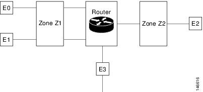
•![]() Interfaces E0 and E1 are members of the security zone Z1.
Interfaces E0 and E1 are members of the security zone Z1.
•![]() Interface E2 is a member of the security zone Z2.
Interface E2 is a member of the security zone Z2.
•![]() Interface E3 is not a member of any of the security zone.
Interface E3 is not a member of any of the security zone.
In this scenario, the following situations exist:
•![]() Traffic flows freely between the interfaces E0 and E1 because they are members of the same security zone (Z1).
Traffic flows freely between the interfaces E0 and E1 because they are members of the same security zone (Z1).
•![]() If no policies are configured, traffic will not flow between interfaces (for example, E0 and E2, E1 and E2, E3 and E1, and E3 and E2).
If no policies are configured, traffic will not flow between interfaces (for example, E0 and E2, E1 and E2, E3 and E1, and E3 and E2).
•![]() Traffic can flow between E0 or E1 and E2 interfaces only when an explicit policy is configured to permit the traffic between the zone Z1 and zone Z2.
Traffic can flow between E0 or E1 and E2 interfaces only when an explicit policy is configured to permit the traffic between the zone Z1 and zone Z2.
•![]() Traffic can never flow between E3 and E0/E1/E2 interfaces because E3 is not a part of any security zone.
Traffic can never flow between E3 and E0/E1/E2 interfaces because E3 is not a part of any security zone.
The following topics provide more information:
Managing Applications
This feature allows you to assign or un-assign the Transmission Control Protocol (TCP) / User Datagram Protocol (UDP) ports to an application.
Note ![]() When you click the Save or Delete button, the changes are deployed on the device. You cannot review the CLI of the requested operation and also, you cannot remove the operation request from the pending changes queue. If you make any changes in the CLI that starts with the "EMS_" to configure the objects is unsupported and may cause unexpected behavior.
When you click the Save or Delete button, the changes are deployed on the device. You cannot review the CLI of the requested operation and also, you cannot remove the operation request from the pending changes queue. If you make any changes in the CLI that starts with the "EMS_" to configure the objects is unsupported and may cause unexpected behavior.
Editing Applications
To assign or un-assign the TCP/UDP ports to an application, follow these steps.
Step 1 ![]() Choose Operate > Device Work Center.
Choose Operate > Device Work Center.
Step 2 ![]() Select the device from the list or click Add to create a new device, then configure the device.
Select the device from the list or click Add to create a new device, then configure the device.
Step 3 ![]() After selecting the device, click Configuration. The Feature Selector panel appears.
After selecting the device, click Configuration. The Feature Selector panel appears.
Step 4 ![]() From the Feature Selector panel, choose Zone Based Firewall > Applications. The Applications page appears.
From the Feature Selector panel, choose Zone Based Firewall > Applications. The Applications page appears.
Step 5 ![]() To assign or unassign the TCP/UDP ports to an application, click on the application and update its TCP/UDP ports value.
To assign or unassign the TCP/UDP ports to an application, click on the application and update its TCP/UDP ports value.
a. ![]() Assign port(s) by defining one or more ports separated by comma (For example: 1234, 2222 and so on).
Assign port(s) by defining one or more ports separated by comma (For example: 1234, 2222 and so on).
b. ![]() Assign port(s) by defining the port range (For example: 1111-1118). You can also assign a group of ports or port range.
Assign port(s) by defining the port range (For example: 1111-1118). You can also assign a group of ports or port range.
c. ![]() Unassign port(s) by deleting the existing port values.
Unassign port(s) by deleting the existing port values.
Table 6-20 lists the elements on the Applications page.
Step 6 ![]() Click Save to save the configurations.
Click Save to save the configurations.
Managing Default Parameters
To change the Default Parameters Map, follow these steps.
Step 1 ![]() Choose Operate > Device Work Center.
Choose Operate > Device Work Center.
Step 2 ![]() Select the device from the list or click Add to create a new device, then configure the device.
Select the device from the list or click Add to create a new device, then configure the device.
Step 3 ![]() After selecting the device, click Configuration. The Feature Selector panel appears.
After selecting the device, click Configuration. The Feature Selector panel appears.
Step 4 ![]() From the Feature Selector panel, choose Zone Based Firewall > Default Parameters Map.
From the Feature Selector panel, choose Zone Based Firewall > Default Parameters Map.
Step 5 ![]() From the Default Parameters Map page, change the parameters map value.
From the Default Parameters Map page, change the parameters map value.
Note ![]() You can change the default parameters only on ISR devices.
You can change the default parameters only on ISR devices.
Step 6 ![]() Click Save to save the configuration.
Click Save to save the configuration.
Managing Interfaces
A virtual interface is a logical interface configured with generic configuration information for a specific purpose or configured for a common to specific users. The zone member information is acquired from a RADIUS server, and then the dynamically created interface is made as a member of that zone.
Configuring Interfaces
To assign the interfaces to the zone and un-assign the interface from a specific zone, follow these steps.
Step 1 ![]() Choose Operate > Device Work Center.
Choose Operate > Device Work Center.
Step 2 ![]() Select the device from the list or click Add to create a new device, then configure the device.
Select the device from the list or click Add to create a new device, then configure the device.
Step 3 ![]() After selecting the device, click Configuration. The Feature Selector panel appears.
After selecting the device, click Configuration. The Feature Selector panel appears.
Step 4 ![]() From the Feature Selector panel, choose Zone Based Firewall > Interfaces.
From the Feature Selector panel, choose Zone Based Firewall > Interfaces.
Step 5 ![]() In the Interface page, select the interface you want to change and click the down arrow icon. The Zone dialog box appears.
In the Interface page, select the interface you want to change and click the down arrow icon. The Zone dialog box appears.
Step 6 ![]() In the Zone dialog box, select the new security zone for the interface. If the selected interface is already assigned to a zone, you will get a warning message.
In the Zone dialog box, select the new security zone for the interface. If the selected interface is already assigned to a zone, you will get a warning message.
Step 7 ![]() Click Yes on the warning message if you want to change the assignment of that interface.
Click Yes on the warning message if you want to change the assignment of that interface.
Step 8 ![]() To un-assign the interface from the specific zone, select the interface and delete the zone information.
To un-assign the interface from the specific zone, select the interface and delete the zone information.
Table 6-21 lists the elements on the Interfaces page.
Step 9 ![]() Click:
Click:
•![]() Save to save and apply your changes.
Save to save and apply your changes.
•![]() Cancel to exit without saving.
Cancel to exit without saving.
Managing Policy Rules
The policy rule section allows you to create a new firewall policy rule, change the existing policy rule, delete the policy rule, and change the policy rule order. When you create the firewall policy rule, it is up to you to define the location in the policy table.
Creating Policy Rules
To create the policy rules, follow these steps.
Step 1 ![]() Choose Operate > Device Work Center.
Choose Operate > Device Work Center.
Step 2 ![]() Select the device from the list or click Add to create a new device, then configure the device.
Select the device from the list or click Add to create a new device, then configure the device.
Step 3 ![]() After selecting the device, click Configuration. The Feature Selector panel appears.
After selecting the device, click Configuration. The Feature Selector panel appears.
Step 4 ![]() From the Feature Selector panel, choose Zone Based Firewall > Policy Rules. The Firewall Rules page appears.
From the Feature Selector panel, choose Zone Based Firewall > Policy Rules. The Firewall Rules page appears.
Step 5 ![]() From the Firewall Rules page, click the Add Rule button and enter the information, such as Name, Source Zone, Destination Zone, Source IP address, Destination IP address, Service, and Action. The source zone and the destination zone must be different. To move the rules, click on the down arrow icon on the Add Rule button. You can place the rule at the top of the list, bottom of the list or move the rule after or before the selected rule in the list.
From the Firewall Rules page, click the Add Rule button and enter the information, such as Name, Source Zone, Destination Zone, Source IP address, Destination IP address, Service, and Action. The source zone and the destination zone must be different. To move the rules, click on the down arrow icon on the Add Rule button. You can place the rule at the top of the list, bottom of the list or move the rule after or before the selected rule in the list.
Note ![]() The name field is optional. If you do not provide the name for the firewall rule, the system generates a name for the firewall rule. You cannot use these formats rule_<number> or EMS_rule_<number> to create the firewall rule name (For example, rule_1). These are system reserved formats.
The name field is optional. If you do not provide the name for the firewall rule, the system generates a name for the firewall rule. You cannot use these formats rule_<number> or EMS_rule_<number> to create the firewall rule name (For example, rule_1). These are system reserved formats.
Step 6 ![]() To add the source and the destination IP address, click the add icon. The Source/Destination IP address dialog box appears.
To add the source and the destination IP address, click the add icon. The Source/Destination IP address dialog box appears.
a. ![]() From the Source/Destination IP address dialog box, check the Any check box to set the value to any.
From the Source/Destination IP address dialog box, check the Any check box to set the value to any.
a. ![]() Enter the source/ destination IP addresses.
Enter the source/ destination IP addresses.
b. ![]() Click the Add button to add the new IP address and the subnet.
Click the Add button to add the new IP address and the subnet.
c. ![]() Click Delete to delete the existing value.
Click Delete to delete the existing value.
d. ![]() Click Ok to save the configurations.
Click Ok to save the configurations.
e. ![]() Click Cancel to cancel all the changes you have made without sending them to the router.
Click Cancel to cancel all the changes you have made without sending them to the router.
Step 7 ![]() Set the Service values. To add or remove the Application, click the down arrow icon. The Firewall Service dialog box appears.
Set the Service values. To add or remove the Application, click the down arrow icon. The Firewall Service dialog box appears.
a. ![]() In the Firewall Service dialog box, check the Application check box to select the application to inspect.
In the Firewall Service dialog box, check the Application check box to select the application to inspect.
b. ![]() To select an ACL Based Application, select either the TCP or UDP or ICMP application.
To select an ACL Based Application, select either the TCP or UDP or ICMP application.
c. ![]() Use the navigation arrow buttons to navigate front and back.
Use the navigation arrow buttons to navigate front and back.
d. ![]() Click the plus + button to save the configurations.
Click the plus + button to save the configurations.
Step 8 ![]() Select the appropriate action. The options are: Drop, Drop and Log, Inspect, Pass, and Pass and Log.
Select the appropriate action. The options are: Drop, Drop and Log, Inspect, Pass, and Pass and Log.
Step 9 ![]() If you select the action to inspect, click the Configure button in the Advance options column. The Advanced Parameters Configuration dialog box appears.
If you select the action to inspect, click the Configure button in the Advance options column. The Advanced Parameters Configuration dialog box appears.
Step 10 ![]() In the Advanced Parameters Configuration dialog box, do the following:
In the Advanced Parameters Configuration dialog box, do the following:
a. ![]() To customize the device default value, check the parameter check box and set the new value.
To customize the device default value, check the parameter check box and set the new value.
b. ![]() To apply the device default value, uncheck the parameter check box.
To apply the device default value, uncheck the parameter check box.
c. ![]() To view the firewall rule default parameters, see "Managing Default Parameters" section.
To view the firewall rule default parameters, see "Managing Default Parameters" section.
d. ![]() When you rest your cursor on the Advanced Options icon, the configured parameters will be displayed in the quick view window.
When you rest your cursor on the Advanced Options icon, the configured parameters will be displayed in the quick view window.
Table 6-22 lists the elements on the policy rule page.
|
|
|
|---|---|
Name |
(Optional) Enter a name for the policy rule. |
Source Zone |
Enter the name of the source zone. The source zone specifies the name of the zone from which the traffic is originating. |
Destination Zone |
Enter the name of the destination zone. The destination zone specifies the name of the router to which the traffic is bound. |
Source |
Enter the source IP address of the inspected data. The valid parameters are: • • • |
Destination |
Enter the destination IP address of the inspected data. The valid parameters are: • • • |
Service |
The service of the inspected data. The valid parameters are: • • • |
Action |
Choose the action to perform on the traffic when there is a match on Rule condition. The rule matches when: • • The action options are: • • • • • |
Advance Options |
Specify the configuration parameters to set the Firewall Rule Parameter-Map behavior when the Action option is set to Inspect. |
Step 11 ![]() Click Save to apply the rule to the device.
Click Save to apply the rule to the device.
Editing Policy Rule
To edit the existing Policy Rule, follow these steps.
Step 1 ![]() Choose Operate > Device Work Center.
Choose Operate > Device Work Center.
Step 2 ![]() Select the device from the list or click Add to create a new device, then configure the device.
Select the device from the list or click Add to create a new device, then configure the device.
Step 3 ![]() After selecting the device, click Configuration. The Feature Selector panel appears.
After selecting the device, click Configuration. The Feature Selector panel appears.
Step 4 ![]() From the Feature Selector panel, choose Zone Based Firewall > Policy Rules.
From the Feature Selector panel, choose Zone Based Firewall > Policy Rules.
Step 5 ![]() In the Firewall Rules page, choose one of the following options:
In the Firewall Rules page, choose one of the following options:
a. ![]() Click on the Rules parameters row and edit the parameters. or
Click on the Rules parameters row and edit the parameters. or
b. ![]() Check the check box to select the rule, and then click the Edit button. The selected Rule entity opens for edit.
Check the check box to select the rule, and then click the Edit button. The selected Rule entity opens for edit.
Step 6 ![]() Click Save to apply the changes in the device.
Click Save to apply the changes in the device.
Deleting the Policy Rule
To delete the existing Policy Rule, follow these steps.
Step 1 ![]() Choose Operate > Device Work Center.
Choose Operate > Device Work Center.
Step 2 ![]() Select the device from the list or click Add to create a new device, then configure the device.
Select the device from the list or click Add to create a new device, then configure the device.
Step 3 ![]() After selecting the device, click the Configuration. The Feature Selector panel appears.
After selecting the device, click the Configuration. The Feature Selector panel appears.
Step 4 ![]() From the Feature Selector panel, choose Zone Based Firewall > Policy Rules.
From the Feature Selector panel, choose Zone Based Firewall > Policy Rules.
Step 5 ![]() In the Firewall Rules page, check the check box to select the rules, and then click the Delete button.
In the Firewall Rules page, check the check box to select the rules, and then click the Delete button.
Step 6 ![]() Click Ok on the warning message to delete the policy rule. The selected policy rule is deleted from the device.
Click Ok on the warning message to delete the policy rule. The selected policy rule is deleted from the device.
Changing the Firewall Rule Order
The class-default rules always appear at the bottom of the list and their location is fixed. The regular rules cannot be moved beneath the class-default rules.
To change the Policy Rule order, follow these steps.
Step 1 ![]() Choose Operate > Device Work Center.
Choose Operate > Device Work Center.
Step 2 ![]() Select the device from the list or click Add to create a new device, then configure the device.
Select the device from the list or click Add to create a new device, then configure the device.
Step 3 ![]() After selecting the device, click Configuration. The Feature Selector panel appears.
After selecting the device, click Configuration. The Feature Selector panel appears.
Step 4 ![]() From the Feature Selector panel, choose Zone Based Firewall > Policy Rules.
From the Feature Selector panel, choose Zone Based Firewall > Policy Rules.
Step 5 ![]() In the Firewall Rules page, to move the rule to a specific row, drag and drop the rule to the new location.
In the Firewall Rules page, to move the rule to a specific row, drag and drop the rule to the new location.
Managing Services
This feature allows you to create, update or delete the service element. You can assign or unassign the TCP/UDP ports to an application.
Creating Services
To create the services, follow these steps.
Step 1 ![]() Choose Operate > Device Work Center.
Choose Operate > Device Work Center.
Step 2 ![]() Select the device from the list or click Add to create a new device, then configure the device.
Select the device from the list or click Add to create a new device, then configure the device.
Step 3 ![]() After selecting the device, click Configuration. The Feature Selector panel appears.
After selecting the device, click Configuration. The Feature Selector panel appears.
Step 4 ![]() From the Feature Selector panel, choose Zone Based Firewall > Services. The Service page appears.
From the Feature Selector panel, choose Zone Based Firewall > Services. The Service page appears.
Step 5 ![]() In the Service page, click the Add Service button to create a new service.
In the Service page, click the Add Service button to create a new service.
Step 6 ![]() In the Service page, enter the Service Name.
In the Service page, enter the Service Name.
Step 7 ![]() To assign Applications, click the down arrow icon. The Applications Object Selector dialog box appears.
To assign Applications, click the down arrow icon. The Applications Object Selector dialog box appears.
a. ![]() In the Applications dialog box, check the Applications check box to select the applications from the list (can be multiple selection).
In the Applications dialog box, check the Applications check box to select the applications from the list (can be multiple selection).
b. ![]() Click OK to accept the changes or Cancel to cancel the changes.
Click OK to accept the changes or Cancel to cancel the changes.
Table 6-23 lists the elements on the Service page.
Step 8 ![]() Click Save to apply your changes to the device.
Click Save to apply your changes to the device.
Editing Service
To edit the existing service, follow these steps.
Step 1 ![]() Choose Operate > Device Work Center.
Choose Operate > Device Work Center.
Step 2 ![]() Select the device from the list or click Add to create a new device, then configure the device.
Select the device from the list or click Add to create a new device, then configure the device.
Step 3 ![]() After selecting the device, click Configuration. The Feature Selector panel appears.
After selecting the device, click Configuration. The Feature Selector panel appears.
Step 4 ![]() From the Feature Selector panel, choose Zone Based Firewall > Services.
From the Feature Selector panel, choose Zone Based Firewall > Services.
Step 5 ![]() In the Service page:
In the Service page:
a. ![]() Click on the Service parameters row and edit the parameters. or
Click on the Service parameters row and edit the parameters. or
b. ![]() Select the service, and click the Edit button. The selected Service entity opens for editing. You can add new applications or remove an already selected application.
Select the service, and click the Edit button. The selected Service entity opens for editing. You can add new applications or remove an already selected application.
c. ![]() To remove an application from the selected list, rest your cursor on the application name, and click the X icon.
To remove an application from the selected list, rest your cursor on the application name, and click the X icon.
Step 6 ![]() Click Save to save the configuration.
Click Save to save the configuration.
Deleting the Service
To delete the existing service, follow these steps.
Step 1 ![]() Choose Operate > Device Work Center.
Choose Operate > Device Work Center.
Step 2 ![]() Select the device from the list or click Add to create a new device, then configure the device.
Select the device from the list or click Add to create a new device, then configure the device.
Step 3 ![]() After selecting the device, click Configuration. The Feature Selector panel appears.
After selecting the device, click Configuration. The Feature Selector panel appears.
Step 4 ![]() From the Feature Selector panel, choose Zone Based Firewall > Services.
From the Feature Selector panel, choose Zone Based Firewall > Services.
Step 5 ![]() From the Service page, select the service, and then click the Delete button.
From the Service page, select the service, and then click the Delete button.
Step 6 ![]() Click Ok on the warning message to delete the service. The selected service is deleted.
Click Ok on the warning message to delete the service. The selected service is deleted.
Creating Security Zone
To create the security zone, follow these steps,
Note ![]() The Zone Based Firewall feature is supported on ASR platform from the IOS version 3.5 or later. The Zone Based Firewall feature is supported on ISR platform from the IOS release 12.4(24)T or later.
The Zone Based Firewall feature is supported on ASR platform from the IOS version 3.5 or later. The Zone Based Firewall feature is supported on ISR platform from the IOS release 12.4(24)T or later.
Step 1 ![]() Choose Operate > Device Work Center.
Choose Operate > Device Work Center.
Step 2 ![]() Select the device from the list or click Add to create a new device, then configure the device.
Select the device from the list or click Add to create a new device, then configure the device.
Step 3 ![]() After selecting the device, click Configuration. The Feature Selector panel appears.
After selecting the device, click Configuration. The Feature Selector panel appears.
Step 4 ![]() From the Feature Selector panel, choose Zone Based Firewall > Zones, and click the Add Zone button to create the security zone.
From the Feature Selector panel, choose Zone Based Firewall > Zones, and click the Add Zone button to create the security zone.
Step 5 ![]() In the security zone page, enter the Zone Name.
In the security zone page, enter the Zone Name.
Step 6 ![]() Select the VRF of the zone.
Select the VRF of the zone.
a. ![]() VRF selection will affect the interface that can be assigned to the security zone
VRF selection will affect the interface that can be assigned to the security zone
b. ![]() If the user selects the default VRF option, then the security zone can be assigned only to the interfaces that are not related to any other VRF.
If the user selects the default VRF option, then the security zone can be assigned only to the interfaces that are not related to any other VRF.
Step 7 ![]() To assign the interfaces to the security zone, click the down arrow icon. The Interface Object Selector dialog box appears.
To assign the interfaces to the security zone, click the down arrow icon. The Interface Object Selector dialog box appears.
a. ![]() In the Interface selector dialog box, check the Interface check box to select the interface from the list (can be multiple selection).
In the Interface selector dialog box, check the Interface check box to select the interface from the list (can be multiple selection).
b. ![]() Click Ok to save the configuration.
Click Ok to save the configuration.
c. ![]() Click Cancel to cancel all the changes you have made without sending them to the router.
Click Cancel to cancel all the changes you have made without sending them to the router.
Step 8 ![]() In the Advance options column, click the Configure button. The Advanced Parameters Configuration dialog box appears.
In the Advance options column, click the Configure button. The Advanced Parameters Configuration dialog box appears.
Step 9 ![]() In the Advanced Parameters Configuration dialog box, do the following:
In the Advanced Parameters Configuration dialog box, do the following:
a. ![]() Check the Alert check box and click the On radio button to set the alert.
Check the Alert check box and click the On radio button to set the alert.
b. ![]() Check the Maximum Detection check box to set the maximum detection.
Check the Maximum Detection check box to set the maximum detection.
c. ![]() Check the TCP SYN-Flood Rate per Destination check box to set the TCP flood rate.
Check the TCP SYN-Flood Rate per Destination check box to set the TCP flood rate.
d. ![]() Check the Basic Threat Detection Parameters check box and click the On radio button to configure the FW drop threat detection rate, FW inspect threat detection rate, and FW SYN attack threat detection rate.
Check the Basic Threat Detection Parameters check box and click the On radio button to configure the FW drop threat detection rate, FW inspect threat detection rate, and FW SYN attack threat detection rate.
Step 10 ![]() Click:
Click:
•![]() Ok to save configuration.
Ok to save configuration.
•![]() Cancel to exit without saving.
Cancel to exit without saving.
Step 11 ![]() To edit the existing security zone parameters, select the zone, and click the Configure button on the Advance options column. The Advanced Parameters Configuration dialog box appears.
To edit the existing security zone parameters, select the zone, and click the Configure button on the Advance options column. The Advanced Parameters Configuration dialog box appears.
Step 12 ![]() In the Advanced Parameters Configuration dialog box, edit the values and click Save to save the changes. When you rest your cursor on the Advanced Options icon, the configured parameters will be displayed in the quick view window.
In the Advanced Parameters Configuration dialog box, edit the values and click Save to save the changes. When you rest your cursor on the Advanced Options icon, the configured parameters will be displayed in the quick view window.
Note ![]() By default, the Advanced configurations parameters are disabled.
By default, the Advanced configurations parameters are disabled.
Table 6-24 lists the elements on the Security Zone page.
Step 13 ![]() Enter the description for the zone.
Enter the description for the zone.
Step 14 ![]() Click:
Click:
•![]() Save to save the changes.
Save to save the changes.
•![]() Cancel to exit without saving.
Cancel to exit without saving.
Editing Security Zone
To edit the existing security zone, follow these steps.
Step 1 ![]() Choose Operate > Device Work Center.
Choose Operate > Device Work Center.
Step 2 ![]() Select the device from the list or click Add to create a new device, then configure the device.
Select the device from the list or click Add to create a new device, then configure the device.
Step 3 ![]() After selecting the device, click the Configuration. The Feature Selector panel appears.
After selecting the device, click the Configuration. The Feature Selector panel appears.
Step 4 ![]() From the Feature Selector left panel, choose Zone Based Firewall > Zones.
From the Feature Selector left panel, choose Zone Based Firewall > Zones.
Step 5 ![]() In the Security Zone page, choose one of the following options:
In the Security Zone page, choose one of the following options:
a. ![]() Click on the Zone parameters row, and edit the parameters. or
Click on the Zone parameters row, and edit the parameters. or
b. ![]() Select the zone, and click the Edit button. The selected Zone entity opens for editing.
Select the zone, and click the Edit button. The selected Zone entity opens for editing.
Step 6 ![]() Click the add icon to assign the interface to the zone or to un-assign the existing interfaces from the zone You can also change the Description of the zone.
Click the add icon to assign the interface to the zone or to un-assign the existing interfaces from the zone You can also change the Description of the zone.
Step 7 ![]() Click Save to save the configuration.
Click Save to save the configuration.
Deleting the Security Zone
To delete the existing security zone, follow these steps.
Step 1 ![]() Choose Operate > Device Work Center.
Choose Operate > Device Work Center.
Step 2 ![]() Select the device from the list or click Add to create a new device, then configure the device.
Select the device from the list or click Add to create a new device, then configure the device.
Step 3 ![]() After selecting the device, click the Configuration. The Feature Selector panel appears.
After selecting the device, click the Configuration. The Feature Selector panel appears.
Step 4 ![]() From the Feature Selector panel, choose Zone Based Firewall > Zones.
From the Feature Selector panel, choose Zone Based Firewall > Zones.
Step 5 ![]() In the Security Zone page, select the security zone, and then click the Delete button.
In the Security Zone page, select the security zone, and then click the Delete button.
Step 6 ![]() Click Ok on the warning message to delete the security zone. The selected zone is deleted.
Click Ok on the warning message to delete the security zone. The selected zone is deleted.
Configuring Default-Zone
To configure the default zone, follow these steps.
Note ![]() The Default-Zone feature is supported only on ASR platform.
The Default-Zone feature is supported only on ASR platform.
Step 1 ![]() Choose Operate > Device Work Center.
Choose Operate > Device Work Center.
Step 2 ![]() Select the device from the list or click Add to create a new device, then configure the device.
Select the device from the list or click Add to create a new device, then configure the device.
Step 3 ![]() After selecting the device, click Configuration. The Feature Selector panel appears.
After selecting the device, click Configuration. The Feature Selector panel appears.
Step 4 ![]() From the Feature Selector panel, choose Zone Based Firewall > Zones.
From the Feature Selector panel, choose Zone Based Firewall > Zones.
Step 5 ![]() In the Security Zone page, click the Default Zone button to enable or disable the default security zone in the device. The device will host all the interfaces that are not related to any zone.
In the Security Zone page, click the Default Zone button to enable or disable the default security zone in the device. The device will host all the interfaces that are not related to any zone.
Step 6 ![]() Click OK to save the configuration.
Click OK to save the configuration.
Using Reports for Monitoring
Prime NCS (WAN) reporting helps you monitor the system and network health as well as troubleshoot problems. Reports can be run immediately or scheduled to run at a time you specify. Once defined, the reports can be saved for future diagnostic use or scheduled to run and report on a regular basis.
Reports are saved in either CSV or PDF format and are either saved to a file on Prime NCS (WAN) for later download or e-mailed to a specific e-mail address.
Choose Tools > Reports > Report Launch Pad to view the list of available reports.

Tip ![]() Rest your cursor on the information icon next to the report type to view report details.
Rest your cursor on the information icon next to the report type to view report details.
Creating and Running New Reports
Step 1 ![]() Choose Tools > Reports > Report Launch Pad.
Choose Tools > Reports > Report Launch Pad.
Step 2 ![]() Click New next to the report you want to create.
Click New next to the report you want to create.
Step 3 ![]() Enter report details, then click
Enter report details, then click
•![]() Save—To save this report setup without immediately running the report. The report will automatically run at the scheduled time.
Save—To save this report setup without immediately running the report. The report will automatically run at the scheduled time.
•![]() Save and Run—To save this report setup and to immediately run the report.
Save and Run—To save this report setup and to immediately run the report.
•![]() Run—To run the report without saving the report setup.
Run—To run the report without saving the report setup.
•![]() Save and Export—To save the report and export the results to either CSV or PDF format.
Save and Export—To save the report and export the results to either CSV or PDF format.
•![]() Save and Email—To save the report and e-mail the results.
Save and Email—To save the report and e-mail the results.
Viewing Scheduled Reports
To view and manage all currently scheduled reports, choose Tools > Reports > Scheduled Run Results.
Viewing Saved Report Templates
When you have created a report that contains all the parameters necessary, you can save that report template.
Step 1 ![]() Choose Tools > Reports > Saved Report Templates.
Choose Tools > Reports > Saved Report Templates.
Step 2 ![]() Choose which saved report template to show by selecting from the following fields:
Choose which saved report template to show by selecting from the following fields:
•![]() Report Category—Choose the appropriate report category from the drop-down list or choose All.
Report Category—Choose the appropriate report category from the drop-down list or choose All.
•![]() Report Type—Choose the appropriate report type from the drop-down list or choose All. The Report Type selections change depending on the selected report category.
Report Type—Choose the appropriate report type from the drop-down list or choose All. The Report Type selections change depending on the selected report category.
•![]() Scheduled—Choose All, Enabled, Disabled, or Expired to filter the Saved Report Templates list by scheduled status.
Scheduled—Choose All, Enabled, Disabled, or Expired to filter the Saved Report Templates list by scheduled status.
Using Packet Capture for Monitoring and Troubleshooting
Prime NCS (WAN) allows you to run capture traffic in your network to help monitor network usage, gather network statistics, and analyze network problems.
Step 1 ![]() Choose Tools > Packet Capture, then click Create.
Choose Tools > Packet Capture, then click Create.
Step 2 ![]() Specify the required capture session parameters, then click Create.
Specify the required capture session parameters, then click Create.
Diagnosing Site Connectivity Issues
You can use the Prime NCS (WAN) dahsboards to monitor your network and locate problematic devices in your network, and then use the Device Workcenter to change the device configuration.
Step 1 ![]() Choose Operate > Detailed Dashboards, choose the site for which you are experiencing connectivity issues, then click Go.
Choose Operate > Detailed Dashboards, choose the site for which you are experiencing connectivity issues, then click Go.
Step 2 ![]() View data reported under Device Reachability Status and Top N Devices with Most Alarms to determine the source of the issue.
View data reported under Device Reachability Status and Top N Devices with Most Alarms to determine the source of the issue.
Step 3 ![]() Click on the name of the device for which you see the most alarms. This launches the 360-degree view of the device.
Click on the name of the device for which you see the most alarms. This launches the 360-degree view of the device.
Step 4 ![]() Click the Alarm Browser icon to view the alarms for that device. Expand the alarm to view details for the alarm.
Click the Alarm Browser icon to view the alarms for that device. Expand the alarm to view details for the alarm.
Step 5 ![]() To compare the configuration on the device to a previously known good configuration, choose Operate > Device Work Center, then select the device whose configuration you want to change.
To compare the configuration on the device to a previously known good configuration, choose Operate > Device Work Center, then select the device whose configuration you want to change.
Step 6 ![]() Click the Configuration Archive tab, expand the arrow to view additional options, then select the configuration type and a configuration against which to compare.
Click the Configuration Archive tab, expand the arrow to view additional options, then select the configuration type and a configuration against which to compare.
Step 7 ![]() Change or rollback the configuration. See Rolling Back Device Configuration Versions for more information.
Change or rollback the configuration. See Rolling Back Device Configuration Versions for more information.
 Feedback