Managing Scopes, Prefixes, Links, and Networks

The Dynamic Host Configuration Protocol (DHCP) is an industry-standard protocol for automatically assigning IP configuration to devices. DHCP uses a client/server model for address allocation. As administrator, you can configure one or more DHCP servers to provide IP address assignment and other TCP/IP-oriented configuration information to your devices. DHCP frees you from having to manually assign an IP address to each client. The DHCP protocol is described in RFC 2131. For an introduction to the protocol, see Introduction to Dynamic Host Configuration.

This chapter describes how to set up scopes, prefixes, and links. Before clients can use DHCP for address assignment, you must add at least one scope (dynamic address pool) or prefix to the server.

Managing Scopes

This section describes how to define and configure scopes for the DHCP server. A scope consists of one or more ranges of dynamic addresses in a subnet that a DHCP server manages. You must define one or more scopes before the DHCP server can provide leases to clients. For more on listing leases and defining lease reservations for a scope, see Managing Leases.

Creating Scopes

Creating scopes is a local cluster function. Each scope needs to have the following:

  • Name
  • Policy that defines the lease times, grace period, and options
  • Network address and subnet mask
  • Range or ranges of addresses

You can configure scopes at the local cluster only. The web UI pages are different for local basic and advanced modes.

Local Basic Web UI

Procedure

Step 1

From the Design menu, choose Scopes from the DHCPv4 submenu to open the List/Add DHCP Scopes page.

Step 2

Choose a VPN for the scope from the Settings drop-down list at the top of the web UI, if necessary.

Step 3

Click the Add Scopes icon in the Scopes pane, enter a scope name, enter the subnet IP address and choose a mask value from the drop-down list.

Step 4

If desired, choose a preconfigured class of service (client-class) for the scope from the drop-down list.

Step 5

Click Add DHCP Scope .

Step 6

Reload the DHCP server.

Note 
When a scope is created in Basic mode, the range and the router address will be added automatically. If you want to change them, you have to change the mode to Advanced since it cannot be configured on the Basic mode.

Local Advanced Web UI

Procedure

Step 1

From the Design menu, choose Scopes from the DHCPv4 submenu to open the List/Add DHCP Scopes page.

Step 2

Choose a VPN for the scope from the Settings drop-down list at the top of the web UI, if necessary.

Step 3

Click the Add Scopes icon in the Scopes pane, enter a scope name, or leave it blank to use the one defined in the scope name expression of a scope template, if any (see Using Expressions in Scope Templates). In the latter case, choose the scope template. You must always enter a subnet and mask for the scope.

Step 4

Choose a policy for the scope from the drop-down list. The policy defaults to the default policy.

Step 5

Click Add DHCP Scope .

Step 6

Add ranges for addresses in the scope. The ranges can be any subset of the defined scope, but cannot overlap. If you enter just the host number, the range is relative to the netmask. Do not enter ranges that include the local host or broadcast addresses (usually 0 and 255). Add the range and then click Add Range .

Step 7

Reload the DHCP server.

Tip 

To view any leases and reservations associated with the scope, see Managing Leases. To search for leases, see Searching Server-Wide for Leases.


Configuring Multiple Scopes

You can configure multiple scopes (with disjointed address ranges) with the same network number and subnet mask. By default, the DHCP server pools the available leases from all scopes on the same subnet and offers them, in a round-robin fashion, to any client that requests a lease. However, you can also bypass this round-robin allocation by setting an allocation priority for each scope (see Configuring Multiple Scopes Using Allocation Priority).

Configuring the addresses of a a single subnet into multiple scopes helps to organize the addresses in a more natural way for administration. Even though you can configure a virtually unlimited number of leases per scope, if you have a scope with several thousand leases, it can take a while to sort them. This can be a motivation to divide the leases among multiple scopes.

You can divide the leases among the scopes according to the types of leases. Because each scope can have a separate reservations list, you can put the dynamic leases in one scope that has a policy with one set of options and lease times, and all the reservations in another scope with different options and times. Note that in cases where some of the multiple scopes are not connected locally, you should configure the router (having BOOTP relay support) with the appropriate helper address.

Configuring Multiple Scopes for Round-Robin Address Allocation

By default, the DHCP server searches through the multiple scopes in a round-robin fashion. Because of this, you would want to segment the scopes by the kind of DHCP client requests made. When multiple scopes are available on a subnet through the use of secondary scopes, the DHCP server searches through all of them for one that satisfies an incoming DHCP client request. For example, if a subnet has three scopes, only one of which supports dynamic BOOTP, a BOOTP request for which there is no reservation is automatically served by the one supporting dynamic BOOTP.

You can also configure a scope to disallow DHCP requests (the default is to allow them). By using these capabilities together, you can easily configure the addresses on a subnet so that all the DHCP requests are satisfied from one scope (and address range), all reserved BOOTP requests come from a second one, and all dynamic BOOTP requests come from a third. In this way, you can support dynamic BOOTP while minimizing the impact on the address pools that support DHCP clients.

Configuring Multiple Scopes Using Allocation Priority

You can set an allocation priority among scopes instead of the default round-robin behavior described in the previous section. In this way, you can have more control over the allocation process. You can also configure the DHCP server to allocate addresses contiguously from within a subnet and control the blocks of addresses allocated to the backup server when using DHCP server failover (see Managing DHCP Failover).

A typical installation would set the allocation priority of every scope by using the allocation-priority attribute on the scope. Some installations might also want to enable the allocate-first-available attribute on their scopes, although many would not. There is a small performance loss when using allocate-first-available, so you should only use it when absolutely required.

You can control:

  • A hierarchy among scopes of which should allocate addresses first.
  • Whether to have a scope allocate the first available address rather than the default behavior of the least recently accessed one.
  • Allocating contiguous and targeted addresses in a failover configuration for a scope.
  • Priority address allocation server-wide.
  • In cases where the scopes have equal allocation priorities set, whether the server should allocate addresses from those with the most or the least number of available addresses.

When there is more than one scope in a network, then the DHCP must decide which scope to allocate an IP address from when it processes a DHCPDISCOVER request from a DHCP client that is not already associated with an existing address. The algorithm that the DHCP server uses to perform this allocation is described in the following section.

Allocation Priority Algorithm

The DHCP server examines the scopes in a network one at a time to determine if they are acceptable. When it finds an acceptable scope, it tries to allocate an IP address from it to fulfill the DHCPDISCOVER request. The allocation-priority scope attribute is used to direct the DHCP server to examine the scopes in a network in a particular order, because in the absence of any allocation priority, the DHCP server examines the scopes in a round-robin order.

The image below shows an example of a network with nine scopes (which is unusual, but serves to illustrate several possibilities of using allocation priority).

Figure 1. Scope Allocation Priority


Six of these scopes were configured with an allocation priority, and three of them were not. The server examines the six that were configured with an allocation priority first, in lowest to highest priority order. As the server finds an acceptable scope, it tries to allocate an IP address from it. If the server succeeds, it then finishes processing the DHCPDISCOVER request using this address. If it cannot allocate an address from that scope, it continues examining scopes looking for another acceptable one, and tries to allocate an address from it.

This process is straightforward if no scopes have the same allocation priority configured, but in the case where (as in the example in) more than one scope has the same nonzero allocation priority, then the server has to have a way to choose between the scopes of equal priority. The default behavior is to examine the scopes with equal priority starting with the one with the fewest available addresses. This uses up all of the addresses in one scope before using any others from another scope. This is the situation shown in the image above. If you enable the equal-priority-most-available DHCP server attribute, then the situation is reversed and the scope with the most available addresses is examined first when two scopes have equal priority. This spreads out the utilization of the scopes, and more or less evenly distributes the use of addresses across all of the scopes with equal allocation priority set.

You can use this equal-priority-most-available approach because of another feature in the processing of equal priority scopes. In the situation where there are two scopes of equal priority, if the DHCPDISCOVER request, for which the server is trying to allocate an address, also has a limitation-id (that is, it is using the option 82 limitation capability; see Subscriber Limitation Using Option 82), then the DHCP server tries to allocate its IP address from the same scope as that used by some existing client with the same limitation-id (if any). Thus, all clients with the same limitation-id tend to get their addresses allocated from the same scope, regardless of the number of available addresses in the scopes of equal priority or the setting of the equal-priority-most-available server attribute.

To bring this back to the equal-priority-most-available situation, you might configure equal-priority- most-available (and have several equal priority scopes), and then the first DHCP client with a particular limitation-id would get an address from the scope with the most available addresses (since there are no other clients with that same limitation-id). Then all of the subsequent clients with the same limitation-id would go into that same scope. The result of this configuration is that the first clients are spread out evenly among the acceptable, equal priority scopes, and the subsequent clients would cluster with the existing ones with the same limitation-id.

If there are scopes with and without allocation priority configured in the same network, all of the scopes with a nonzero allocation priority are examined for acceptability first. Then, if none of the scopes were found to be acceptable and also had an available IP address, the remaining scopes without any allocation priority are processed in a round-robin manner. This round-robin examination is started at the next scope beyond the one last examined in this network, except when there is an existing DHCP client with the same limitation-id as the current one sending the DHCPDISCOVER. In this case, the round-robin scan starts with the scope from which the existing client IP address was drawn. This causes subsequent clients with the same limitation-id to draw their addresses from the same scope as the first client with that limitation-id, if that scope is acceptable and has available IP addresses to allocate.

Address Allocation Attributes

The attributes that correspond to address allocation are described in the table below.

Table 1. Address Allocation Priority Settings

Attribute

Type

Description

allocation- priority

Scope (set or unset)

If defined, assigns an ordering to scopes such that address allocation takes place from acceptable scopes with a higher priority until the addresses in all those scopes are exhausted. An allocation priority of 0 (the preset value) means that the scope has no allocation priority. A priority of 1 is the highest priority, with each increasing number having a lower priority. You can mix scopes with an allocation priority along with those without one. In this case, the scopes with a priority are examined for acceptability before those without a priority.

If set, this attribute overrides the DHCP server priority-address- allocation attribute setting. However, if allocation-priority is unset and priority-address-allocation is enabled, then the allocation priority for the scope is its subnet address. With allocation-priority unset and priority-address-allocation disabled, the scope is examined in the default round-robin fashion.

allocate-first- available

Scope (enable or disable)

If enabled, forces all allocations for new addresses from this scope to be from the first available address. If disabled (the preset value), uses the least recently accessed address. If set, this attribute overrides the DHCP server priority-address-allocation attribute setting. However, if unset and priority-address-allocation is enabled, then the server still allocates the first available address. With allocate-first-available unset and priority-address-allocation disabled, the scope is examined in the default round-robin fashion.

failover-backup- allocation- boundary

Scope (set or unset)

If allocate-first-available is enabled and the scope is in a failover configuration, this value is the IP address to use as the point from which to allocate addresses to a backup server. Only addresses below this boundary are allocated to the backup server. If there are no available addresses below this boundary, then the addresses above it are allocated to the backup server. The actual allocation works down from this address, while the normal allocation for DHCP clients works up from the lowest address in the scope.

If this attribute is unset or set to zero, then the boundary used is halfway between the first and last addresses in the scope ranges. If there are no available addresses below this boundary, then the first available address is used.

See Figure 9 for an illustration of how addresses are allocated in a scope using this setting.

priority-address- allocation

DHCP (enable or disable)

Provides a way to enable priority address allocation for the entire DHCP server without having to configure it on every scope. (However, the scope allocation-priority setting overrides this one.) If priority-address-allocation is enabled and the scope allocation-priority attribute is unset, then the scope subnet address is used for the allocation priority. If the scope allocate-first-available is unset, then priority address allocation is considered enabled. Of course, when exercising this overall control of the address allocation, the actual priority of each scope depends only on its subnet address, which may or may not be desired.

equal-priority- most-available

DHCP (enable or disable)

By default, when two or more scopes with the same nonzero allocation-priority are encountered, the scope with the least available IP addresses is used to allocate an address for a new client (if that client is not in a limitation list). If equal-priority-most- available is enabled and two or more scopes have the same nonzero allocation priority, then the scope with the most available addresses is used to allocate an address for a new client (if that client is not in a limitation list). In either case, if a client is in a limitation-list, then among those scopes of the same priority, the one that contains other clients in the same list is always used.

Allocating Addresses In Scopes

When trying to allocate an IP address from within a scope, the default action of the DHCP server is to try to allocate the least recently accessed address first, from the list of available leases. But all the operations that require accessing the lease like listing all the leases or all leases in a scope, asking for a specific lease (nrcmd> lease addr), searching leases, or modifying leases (activate, deactivate, or force available) affect the ordering of the leases in the list of available leases with the server.

Operating on a single lease places that lease at the end of the list. Listing leases causes the leases to be arranged in numerical order, making the lowest numbered lease to end up first on the available list. Other operations that require the server to access the lease, like leasequery requests also impacts the order of leases.

Thus, in general there is no way to predict which IP address within a scope is allocated at a given time. Usually this poses no difficulty, but there are times when a more deterministic allocation strategy is desired. To configure a completely deterministic address allocation strategy, you can enable the allocate-first-available attribute on a scope. This causes the available address with the lowest numeric value to be allocated for a DHCP client. Thus, the first client gets the first address in the lowest range, and the second client the second one in that range, and so on. This is shown in the image below.

Figure 2. Address Allocation with allocate-first-available Set


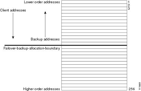
Note that there is some minor performance cost to this deterministic allocation strategy, not so much that you should not use it, but possibly enough so that you should not use it if you do not need it. When using this deterministic allocation strategy approach in a situation where the scope is in a failover relationship, the question of how to allocate the available IP addresses for the backup server comes up on the main server. By default, the address halfway between the lowest and highest ones in the scope becomes the failover-backup-allocation-boundary. The available addresses for the backup server are allocated working down from this boundary (if any addresses are available in that direction). If no address is available below this boundary, then the first available one above the boundary is used for the backup server. You can configure the failover-backup-allocation-boundary for the scope if you want to have a different address boundary than the halfway point.

You would use a deterministic allocation strategy and configure allocate-first-available in situations where you might allocate a scope with a larger number of IP addresses than you were sure you needed. you can later shrink back the ranges in the scope so as to allow moving address space to another network or server. In the nondeterministic approach, the allocated addresses are scattered all over the ranges, and it can be very hard to reconfigure the DHCP clients to free up, say, half of the scope addresses. However, if you configure allocate-first-available, then the allocated addresses tend to cluster low in the scope ranges. It is then probably simpler to remove ranges from a scope that does not need them, so that those addresses can be used elsewhere.

Editing Scopes


Note

You can only make changes to a scope's subnet, if there are no reservations or ranges that conflicts with the change, either in the current scope or any other scope with the same old subnet as those scopes' subnet will also be changed.

Local Advanced Web UI

Procedure

Step 1

Create a scope, as described in Creating Scopes.

Step 2

Reload the DHCP server.

Step 3

Click the name of the scope on the Scopes pane on the List/Add DHCP Scopes page to open the Edit DHCP Scope page. (If a server reload is required, a status message indicates it and you must reload first before proceeding.)

Step 4

Modify the fields or attributes as necessary. You can also modify the name of the scope.

Step 5

To edit the scope embedded policy, see Configuring Embedded Policies for Scopes. To list leases for the scope, see Viewing Leases.

Step 6

Click Save .

Step 7

Reload the DHCP server.


CLI Commands

After you create a scope, look at the properties for all the scopes on the server, use scope list (or scope listnames , scope listbrief , scope name show , or scope name get attribute). Then:

  • To reset an attribute, use scope name set attribute=value [attribute=value ...]. For example, you can reset the name of the scope by using scope name set name =new name.

  • To enable or disable an attribute, use scope name enable attribute or scope name disable attribute.

See the scope command in the CLIGuide.html file in the /docs directory for syntax and attribute descriptions.

Staged and Synchronous Mode

New scopes or modifications to scopes can be in one of two modes—staged or synchronous:

  • Staged —New scopes or modifications to existing scopes are written to the database, but not propagated to the DHCP server until the DHCP server is reloaded.
  • Synchronous —Most new scopes and scope modifications (including deletions) are immediately propagated to the DHCP server (without the need for a reload). Not all scope changes are possible. For example, changing the primary subnet on a scope is not allowed (a reload is required to effect the change). Furthermore, only scope attribute changes can be propagated without a reload. For example, changes to named policies require a DHCP server reload.

If you add or modify a scope while in staged mode and then change the dhcp edit mode to synchronous, the first change in synchronous mode applies all pending changes for that scope (not just the ones made while in synchronous mode).

Local Web UI

To view the current dhcp edit mode or change the dhcp edit mode, click the Settings drop-down list at the top of the web UI and choose Session Settings . If the scope is up to date in the DHCP server, the Total synchronized scopes message appears on the List/Add DHCP Scopes page (in Advanced mode) and the Scope name status: synchronized message appears on the Edit DHCP Scope page (in both modes). If the scope is not up to date, the Scope name status: reload required message is displayed.

CLI Commands

View the dhcp edit mode by using session get dhcp-edit-mode , or set the dhcp edit mode using session set dhcp-edit-mode= {sync | staged }. To view the scopes that are not synchronized with the DHCP server, use scope report-staged-edits . For example:
nrcmd> scope report-staged-edits
 
100 Ok 

example-scope: [reload-required] 

Getting Scope Counts on the Server

You can view the created scopes associated with the DHCP server, hence obtain a count, in the web UI.

CLI Commands

Using the CLI, you can get an exact count of the total scopes for the DHCP server by using dhcp getScopeCount [vpn name | all ]. You can specify a VPN or all VPNs. Omitting the vpn name returns a count for the current VPN. Specifying a failover pair name returns the total scopes and networks for the failover pair. Because a failover pair definition includes explicit VPN settings in its matchlist, these counts are not limited to the current VPN only.

To create a scope, use scope name create address mask [template=template-name] [attribute=value ...]. Each scope must identify its network address and mask. When you create the scope, Cisco Prime Network Registrar places it in its current virtual private network (VPN), as defined by session set current-vpn . You cannot change the VPN once you set it at the time of creation of the scope.

To set a policy for the scope, use scope name set policy .

To add a range of IP addresses to the scope, use scope name addRange start end.

Configuring Embedded Policies for Scopes

When you create a scope, Cisco Prime Network Registrar automatically creates an embedded policy for it. However, the embedded policy has no associated properties or DHCP options until you enable or add them. An embedded policy can be useful, for example, in defining the router for the scope. As Types of Policies describes, the DHCP server looks at the embedded policy of a scope before it looks at its assigned, named policy.


Note

If you delete a scope policy, you remove all of its properties and attributes.

Local Advanced Web UI

Procedure

Step 1

Create a scope, as described in Creating Scopes.

Step 2

Click the name of the scope on the Scopes pane on the List/Add DHCP Scopes page to open the Edit DHCP Scope page.

Step 3

Click Create New Embedded Policy to create a new embedded policy, or Edit Existing Embedded Policy if there is already an existing one, to open the Edit DHCP Embedded Policy for Scope page.

Step 4

Modify the fields, options, and attributes on this page. If necessary, unset attributes.

Step 5

Click Save .


CLI Commands

Create a scope first. In the CLI, scope-policy uses the same syntax as policy , except that it takes the scope name as an argument. Then, to:

  • Determine if there are any embedded property values already set for a scope, use scope-policy scope-name show .

  • Enable or disable an attribute, use scope-policy scope-name enable attribute or scope-policy scope-name disable attribute.

  • Set and unset attributes, use scope-policy scope-name set attribute=value [attribute=value...] and scope-policy scope-name unset attribute.

  • List, set, and unset vendor options (see Using Standard Option Definition Sets).

Configuring Multiple Subnets on a Network

Cisco Prime Network Registrar supports multiple logical subnets on the same network segment, which are also called secondary subnets. With several logical subnets on the same physical network, for example, 192.168.1.0/24 and 192.168.2.0/24, you might want to configure DHCP so that it offers addresses from both pools. By pooling addresses this way, you can increase the available number of leases.

To join two logical subnets, create two scopes, and elect one to be primary and the other to be a secondary. After you configure the secondary subnet, a new client on this physical network gets a lease from one or the other scope on a round-robin basis.

Local Advanced Web UI

Procedure

Step 1

Create a scope (see Creating Scopes) that you will make a secondary scope.

Step 2

Click the name of the scope on the Scopes pane on the List/Add DHCP Scopes page to open the Edit DHCP Scope page.

Step 3

To make this a secondary scope, enter the network address of the subnet of the primary scope in the Primary Subnet attribute field in the Edit DHCP Scope page.

It is common practice for the primary-subnet to correspond directly to the network address of the primary scope or scopes. For example, with examplescope1 created in the 192.168.1.0/24 network, associate examplescope2 with it using primary-subnet =192.168.1.0/24. (Note that if Cisco Prime Network Registrar finds that the defined subnet has an associated scope, it ignores the mask bit definition and uses the one from the primary scope, just in case they do not match.) However, the primary-subnet can be a subnet address that does not have a scope associated with it.

Step 4

Click Save .

Step 5

Restart or reload the server.


CLI Commands

To assign the secondary scope to a primary one, use scope name set primary-subnet =value, then reload the server.

To remove the secondary scope, use scope name unset primary-subnet . When setting the primary-subnet attribute, include the number bits for the network mask, using slash notation. For example, represent the network 192.168.1.0 with mask 255.255.255.0 as 192.168.1.0/24. The mask bits are important. If you omit them, a /32 mask (single IP address) is assumed.

Enabling and Disabling BOOTP for Scopes

The BOOTstrap Protocol (BOOTP) was originally created for loading diskless computers. It was later used to allow a host to obtain all the required TCP/IP information so that it could use the Internet. Using BOOTP, a host can broadcast a request on the network and get the data required from a BOOTP server. The BOOTP server listens for incoming requests and generates responses from a configuration database for the BOOTP clients on that network. BOOTP differs from DHCP in that it has no concept of lease or lease expiration. All addresses that a BOOTP server allocates are permanent.

You can configure the Cisco Prime Network Registrar DHCP server to act like a BOOTP server. In addition, although BOOTP normally requires static address assignments, you can choose either to reserve addresses (and use static assignments) or have addresses dynamically allocated (known as dynamic BOOTP).

When you need to move or decommission a BOOTP client, you can reuse its lease simply by forcing lease availability. See Forcing Lease Availability.

Local Advanced Web UI

On the Edit DHCP Scope page, under BootP Settings, enable the bootp attribute for BOOTP, or the dynamic-bootp attribute for dynamic BOOTP. They are disabled by default. Then click Save .

CLI Commands

Use scope name enable bootp to enable BOOTP, and scope name enable dynamic-bootp to enable dynamic BOOTP. Reload the DHCP server (if in staged dhcp edit mode).

Setting Scopes to Renew-Only

You can control whether to allow existing clients to re-acquire their leases, but not to offer any leases to new clients. A renew-only scope does not change the client associated with any of its leases, other than to allow a client currently using an available IP address to continue to use it.

Local Advanced Web UI

On the Edit DHCP Scope page, under Miscellaneous Settings, explicitly enable the renew-only attribute. Then click Save .

CLI Commands

Use scope name enable renew-only to set a scope to renew-only.

Setting Free Address SNMP Traps on Scopes

You can set SNMP traps to capture unexpected free address events by enabling the traps and setting the low and high thresholds for a scope. You can also set traps based on networks and selection tags instead of scopes.

When setting the threshold values, it is advisable to maintain a small offset between the low and high values, as described in the "Simple Network Management" section in Cisco Prime Network Registrar 11.1 Administration Guide). The offset can be as little as 5%, for example, a low value of 20% and a high value of 25%, which are the preset values.

Here are some variations on how you can set the server and scope values for these attributes:

  • Get each scope to trap and reset the free address values based on the server settings, as long as at least one recipient is configured.
  • Disable the traps at the scope level or specify different percentages for each scope.
  • Disable the traps globally on the server, but turn them on for different scopes.
  • Set the traps at the network level or selection tags level.

Local Advanced and Regional Web UI

Procedure

Step 1

To create a trap configuration, from the Deploy menu, choose Traps under the DHCP submenu to open the List/Add Trap Configurations page.

Step 2

Click the Add Traps icon, enter a name for the trap configuration, choose scope from the Mode drop-down list, and enter the low and high threshold values (they are 20% and 25%, respectively, by default). Click Add AddrTrapConfig . (You can go back to edit these values if you need to.)

Step 3

Edit the created scope to which you want to apply the threshold settings. Under SNMP Trap Settings, enter the name of the trap in the free-address-config attribute field. Click Save .

Step 4

In the regional web UI, you can pull replica trap configurations and push trap configurations to the local cluster on the List/Add Trap Configurations page. You can also reclaim trap configurations.


CLI Commands

Use addr-trap name create to add a trap configuration. To set the thresholds, use the addr-trap name set method (or include the threshold settings while creating the trap). For example:

nrcmd> addr-trap trap-1 create
 
nrcmd> addr-trap trap-1 set low-threshold
 
nrcmd> addr-trap trap-1 set high-threshold

To set the free-address trap, use scope name set free-address-config= trap-name. For example:

nrcmd> scope scope-1 set free-address-config=trap-1

When connected to a regional cluster, you can use the following pull, push, and reclaim commands. For push and reclaim, a list of clusters or "all" may be specified.
  • addr-trap < name | all > pull < ensure | replace | exact > cluster-name [-report-only | -report]

  • addr-trap < name | all > push < ensure | replace | exact > cluster-list [-report-only | -report]

  • addr-trap name reclaim cluster-list [-report-only | -report]

Disabling DHCP for Scopes

You can disable DHCP for a scope if you want to use it solely for BOOTP. See Enabling and Disabling BOOTP for Scopes. You can also temporarily deactivate a scope by disabling DHCP, but deactivation is more often used if you are enabling BOOTP. See Deactivating Scopes.

Local Advanced Web UI

On the Edit DHCP Scope page, under BootP Settings, disable the dhcp attribute and enable the bootp attribute and then click Save .

CLI Commands

Use scope name disable dhcp to disable DHCP. You should also enable BOOTP and reload the server (if in staged dhcp edit mode).

Deactivating Scopes

You might want to temporarily deactivate all the leases in a scope. To do this, you must disable both BOOTP and DHCP for the scope.

Local Advanced Web UI

On the Edit DHCP Scope page, under Miscellaneous Settings, explicitly enable the deactivated attribute. Then click Save .

CLI Commands

Use scope name enable deactivated to disable BOOTP and DHCP for the scope. Reload the DHCP server (if in staged dhcp edit mode).

Removing Scopes


Caution

Although removing a scope from a DHCP server is easy to do, be careful. Doing so compromises the integrity of your network. There are several ways to remove a scope from a server, either by re-using or not re-using addresses, as described in the following sections.


DHCP, as defined by the IETF, provides an address lease to a client for a specific time (defined by the server administrator). Until that time elapses, the client is free to use its leased address. A server cannot revoke a lease and stop a client from using an address. Thus, while you can easily remove a scope from a DHCP server, the clients that obtained leases from it can continue to do so until it expires. This is true even if the server does not respond to their renewal attempts, which happens if the scope was removed.

This does not present a problem if the addresses you remove are not reused in some way. However, if the addresses are configured for another server before the last lease expires, the same address might be used by two clients, which can destabilize the network.

Cisco Prime Network Registrar moves the leases on the removed scope to an orphaned leases pool. When creating a scope, orphaned leases are associated with appropriate scopes.

Removing Scopes if Not Reusing Addresses

You can remove scopes if you are not reusing addresses.

Local Web UI

If you are sure you do not plan to reuse the scope, on the Manage Scopes or List/Add DHCP Scopes page, click the Delete Scopes icon in the Scopes pane after selecting the name, and confirm or cancel the deletion.

CLI Commands

Be sure that you are not immediately planning to reuse the addresses in the scope, then use scope name delete to delete it.

Removing Scopes if Reusing Addresses

If you want to reuse the addresses for a scope you want to remove, you have two alternatives:

  • If you can afford to wait until all the leases in the scope expire —Remove the scope from the server, then wait for the longest lease time set in the policy for the scope to expire. This ensures that no clients are using any addresses from that scope. You can then safely reuse the addresses.
  • If you cannot afford to wait until all the leases in the scope expire —Do not remove the scope. Instead, deactivate it. See Deactivating Scopes. Unlike a removed scope, the server refuses all clients’ renewal requests, which forces many of them to request a new lease. This moves these clients more quickly off the deactivated lease than for a removed scope.

    You can use the ipconfig utility in Windows to cause a client to release (/release ) and re-acquire (/renew ) its leases, thereby moving it off a deactivated lease immediately. You can only issue this utility from the client machine, which makes it impractical for a scope with thousands of leases in use. However, it can be useful in moving the last few clients in a Windows environment off deactivated leases in a scope.

DHCPv6 Addresses

Cisco Prime Network Registrar supports the following IPv6 addressing for DHCP (DHCPv6) based on RFC 8415:

  • Stateless autoconfiguration—The DHCPv6 server does not assign addresses, but instead provides configuration parameters, such as DNS server data, to clients.
  • Stateful autoconfiguration—The DHCPv6 server assigns nontemporary or temporary addresses and provides configuration parameters to clients.
  • Prefix Delegation—The DHCPv6 server delegates prefixes to clients (routers).

Note

RFC 8415 incorporated and obsoleted earlier RFCs: RFC 3315, RFC 3633, RFC 3736, RFC 4242, and RFC 7083.


The DHCPv6 service provides these capabilities:

  • Allocation groups—Allows multiple prefixes to be treated as one from an allocation standpoint, and provides control over the order in which the prefixes are used.
  • Client-classing—You can classify clients and select prefixes based on known clients or packet-based expressions.
  • DNS Updates—DNS server updates of DHCP activity (over IPv4).
  • Extensions—Extend the DHCP server processing by using C/C++ and Tcl extensions.
  • Failover—You can configure a DHCP failover pair so that if one cannot provide leases to requesting clients, another one can take over.
  • LDAP—Allows client entry lookups in an LDAP repository (external to Cisco Prime Network Registrar) and these clients may specify client reservations.
  • Leasequery—Offers leasequery support.
  • Links and prefixes—Similar to DHCPv4 networks and scopes that define the network topology. Each link can have one or more prefixes.
  • Policies and options—You can assign attributes and options to links, prefixes, and clients.
  • Prefix Stability—Clients can retain the delegated prefix when they change their location, that is even when they move from one CMTS to another or move within an address space. Prefix Stability, with appropriate infrastructure support (CMTS, routers), allows the subscriber to be moved or move without requiring a different delegated prefix.
  • SNMP traps—Generate traps for events, such as if the number of leases in a prefix exceeds a certain limit (or drops below a certain limit) or if the server detects duplicate addresses.
  • Reservations—Clients can receive predetermined addresses.
  • Statistics collection and logging—Provides server activity monitoring.
  • VPN support—Provides multiple address spaces (virtual private networks).

The DHCPv6 service requires that the server operating system support IPv6 and that you configure at least one interface on the system for IPv6.

IPv6 Addressing

IPv6 addresses are 128 bits long and are represented as a series of 16-bit hexadecimal fields separated by colons (: ). The A, B, C, D, E, and F in hexadecimal are case insensitive. For example:
2001:db8:0000:0000:0000:0000:0000:0000

A few shortcuts to this addressing are:

  • Leading zeros in a field are optional, so that you can write 09c0 as 9c0, and 0000 as 0.
  • You can represent successive fields of zeros (any number of them) by a double colon (::), but only once in an address (because, if used more than once, the address parser has no way of identifying the size of each block of zeros). This reduces the length of addresses; for example, 2001:db8:0000:0000:0000:0000:0000:0000 can be written:
    2001:db8::
    

Link-local addresses have a scope limited to the link, and use the prefix fe80::/10. Loopback addresses have the address ::1. Multicast addresses have the prefix ff00::/8 (there are no broadcast addresses in IPv6).

The IPv4-compatible addresses in IPv6 are the IPv4 decimal quad addresses prefixed by :: . For example, you can write the IPv4 address interpreted as ::c0a8:1e01 in the form ::192.168.30.1 .

Determining Links and Prefixes

When the DHCPv6 server receives a DHCPv6 message, it determines the links and prefixes it uses to service the request. The server:

  1. Finds the source address:
    1. If the client message was relayed, the server sets the source address to the first nonzero link-address field starting with the Relay-Forward message closest to the client (working outwards). If the server finds a source address, it proceeds to step Step 2.
    2. Otherwise, if the message source address is a link-local address, the server sets the source address to the first address for the interface on which it received the message for which a prefix exists (or 0 if it finds no prefix for any address). It then proceeds to step Step 2
    3. Otherwise, the server sets the source address to the message source address.

    Note

    This behavior can be altered by extensions or by using the client/client-class add-to-environment-dictionary attribute to add a link-address-override attribute value of either an IPv6 address or prefix name. See Table 1.


  2. Locates the prefix for the source address. If the server cannot find a prefix for the source address, it cannot service the client and drops the request.
  3. Locates the link for the prefix. This always exists and is either an explicitly configured link or the implicitly created link based on the prefix address. The link must be a topological link (see Prefix Stability).

Now that the server can determine the client link, it can process the client request. Depending on whether the client request is stateful or prefix-delegated, and on the selection criteria and other factors, the server might use one or more prefixes for the link to service the client request.

This is one area of difference between DHCPv4 and DHCPv6. In DHCPv4, the server selects only one of the scopes from the network to service the client request. In DHCPv6, the server can use all the prefixes for the link. Thus, the server might assign a client an address, or delegate a prefix, from multiple prefixes for the link (subject to selection criteria and other conditions). See Creating and Editing Links.

Generating Addresses

IPv6 addresses are 128-bit addresses (as compared to 32-bit addresses for IPv4). In most cases, DHCPv6 servers assign 64 of those bits, the interface-identifier (EUI-64) portion (see RFC 4291). You can generate addresses by using the client 64-bit interface-identifier or a random number generator. The interface-identifier emulates how stateless autoconfiguration assigns addresses to clients. Unfortunately, there are privacy concerns regarding its use, and it is limited to one address per prefix for the client.

By default, Cisco Prime Network Registrar generates an address using an algorithm similar to that described in RFC 4941 to generate a random interface identifier. These random interface identifiers have a zero value for the universal/local bit to distinguish them from EUI-64-based identifiers. The server also skips randomly generated interface identifiers from ::0 to ::ff so that you can use identifiers for infrastructure devices (such as routers). You can configure whether to assign the interface-identifier (if available) first for each prefix (through the interface-identifier flag of the prefix allocation-algorithm attribute). (See Creating and Editing Prefixes.) If you specify use of the interface-identifier, the server might still use randomly generated addresses if the address is not available to the client, or the client requests multiple addresses on a prefix.

The server generates addresses based on the prefix-configured range (or the prefix address if there is no range). If the range prefix length is shorter than 64, the server supplies only 64 bits and places them in the address interface-identifier field. If the prefix length is longer than 64, the server supplies only the remaining bits of the address. Thus, a /96 range uses 96 bits from the specified range followed by 32 bits of either the client interface-identifier or a randomly generated value. If the resulting address is not available (such as if it is already leased to another client, or to the same client, but on a different binding), the server tries to generate another address. It repeats this process up to at most 500 times.

When DHCP failover is configured, the server generated addresses are always odd addresses on the main and even addresses on the backup.


Note

The DHCP server tests only the randomly generated interface identifier for values from ::0 to ::ff, not the resulting address. Thus, a randomly generated address may end up using an xxxx :xxxx :xxxx :xxxx ::0 through xxxx :xxxx :xxxx :xxxx ::ff address if the length of the prefix is longer than /64 and the prefix bits that extend beyond the /64 boundary are all zero.

Tip

You can also choose from additional address generation algorithms for a prefix and prefix template; see Creating and Editing Prefix Templates.


Generating Delegated Prefixes

The DHCPv6 server uses the best first-fit algorithm when generating delegated prefixes. The server uses the first longest available prefix of the length configured or requested.

For DHCP failover, each server only considers the delegated prefix leases in the available state. When the server is in the PARTNER-DOWN state, the server can also use leases in the other-available or pending-available states after certain time restrictions have passed.

Prefix Stability

Prefix Stability lets you control prefix delegation independent of the network topology. A new link attribute type specifies the type of link.

There are three different link types:

  • Topological—A client on a topological link is allocated leases based on the network segment it is connected to.

  • Location independent—This link type is introduced to support the CableLabs DOCSIS 3.0 concept of CMTS prefix stability. It supports service provider load balancing and reconfiguration events within a group of CMTS (such as in a central office). A subscriber that is moved from one CMTS to another on a location-independent link can retain a delegated prefix. This link type allows movement within a single DHCP server.

  • Universal—This link type is introduced to let subscribers retain a delegated prefix anywhere in the network. Use of this link type requires administrative assignment of the delegated prefixes and use of client or lease reservations. It can be deployed across multiple DHCP servers.


Note

Use of prefix stability has routing implications and requires appropriate support from relay agents (that is, CMTS) in order to advertise the routes. For CMTS prefix stability, these are localized to the CMTS group. The implications are greater for universal prefix stability as routes need to be advertised throughout the service providers network.

CMTS Prefix Stability

Location independent links implement the CableLabs DOCSIS 3.0 requirements for CMTS prefix stability. CMTS prefix stability is possible as long as all prefixes are serviced by a single DHCP server.

If you want to introduce CMTS prefix stability in a particular area, you need to:

  • Modify existing links to specify the same link group name across all of the links within the group. Each CMTS (or CMTS bundle) will have a separate link, but all of these links within the area for which CMTS Prefix Stability is desired need to be made part of the same link group.
  • Create a new link, flagged as location-independent and made part of this link group. Create or move one or more prefix delegation prefixes under this location-independent link - these are the prefixes from which the stable prefixes will be allocated.
  • Remove any prefix delegation prefixes from the existing links that are no longer needed. Note that stateful prefixes (dhcp-type of dhcp) should not be removed.

Note

You can have only one location independent link in a group.

When a client request is received, the server locates the link by checking for the longest matching prefix and using the link of the prefix. However, if this topological link is part of a link group and that group has a location-independent link, the prefixes under the location-independent link will be checked first for possible leases requested by the client. Only if no leases are available from this location-independent link will the topological link be used. This is used for each binding requested by the client.

Any leasing mechanism (lease or client reservations, first best-fit, or extension generated/supplied) may be used with CMTS Prefix Stability as the leases are only known within the single server that services the CMTS group.

Universal Prefix Stability

Universal Prefix Stability lets you retain a delegated prefix regardless of where you connect. To use this feature, you must configure reservations for the delegated prefixes. Either client and lease reservations can be used.

Client reservations let you specify the delegated prefixes in a central LDAP repository that the DHCP servers access dynamically (see Using Client Reservations). Lease reservations are managed centrally on the CCM regional server, and are pushed to each local DHCP with the universal link. Because the complete list of reservations is replicated on each server when using lease reservations, you should consider client reservations for larger deployments.


Note

You can have only one universal link in a particular VPN address space.

If a link is configured with the universal link type, the prefixes in that link are considered first when attempting to allocate a lease for a client. If no lease is available, the prefixes in the location-independent link type from the link group (if any) is used. Finally, the prefixes in the topological link are used.


Note

You can enable both CMTS Prefix Stability and Universal Prefix Stability at the same time, though only one will apply to a subscriber.

Prefix Allocation Groups

Prefix allocation groups let you define multiple prefixes that do not result in multiple lease assignments to clients, and control the order in which the prefixes are used. The allocation-group and allocation-group-priority attributes are introduced to specify this behavior.

All prefixes on a link with the same allocation group name belong to that allocation group. A prefix with no allocation group name is in its own allocation group. At most one lease per binding is allocated across all the prefixes in the same allocation group.

The allocation-group-priority setting controls which prefixes are used. Lower numeric values have higher priority, except for 0 (the default), which has the lowest possible priority. Prefixes with the same priority are ordered by the active lease count, where the prefix with the lowest count will have the highest priority.


Note

The allocation-group name is only specific to the link. Different links can reuse the same allocation group names.

To control the number of leases a client can obtain from an allocation group prefix, you can set the max-leases-per-binding attribute for the DHCP policy. For example, if you set max-leases-per-binding as 1, the client can obtain only one lease from an allocation group prefix. In addition, if more than one lease is already allocated from the same allocation group prefix then the additional leases are revoked (usually the oldest lease is revoked).

Configuring Prefixes and Links

You can configure DHCPv6 prefixes and links directly, or you can create prefix or link templates for them first. See the following subsections:

Creating and Editing Prefixes

You can create prefixes directly (and optionally apply an existing template to it; see Creating and Editing Prefix Templates). These are the prefix attributes that you can set:

  • name—Assigns a name to this prefix.

  • vpn-id—VPN that contains the prefix.

  • address—Prefix (subnet) to which an interface belongs to, using the high-order bits of an IPv6 address.

  • description—Describes the prefix.

  • dhcp-type—Defines how DHCP manages address assignment for a prefix:

    • dhcp (preset value)—Uses the prefix for stateful address assignment.

    • stateless—Uses the prefix for stateless option configuration.

    • prefix-delegation—Uses the prefix for prefix delegation.

    • infrastructure—Uses the prefix to map a client address to a link, when the prefix does not have an address pool.

    • parent—Do not have DHCP use the prefix. But, use it as a container object to group child prefixes. Parent prefixes appear only in the IPv6 address space listing in the web UI, not in the prefixes listing.

  • owner—Owner of the prefix.

  • region—Region for the prefix.

  • reverse-zone-prefix-length—Prefix length of the reverse zone for ip6.arpa updates. (See Determining Reverse Zones for DNS Updates for details.)

  • range—Subrange the server can use to configure prefixes for address assignment. The prefix used depends on the value set for the dhcp-type attribute. If unset, the prefix address applies. This value can specify a longer prefix than the prefix address to limit the range of addresses or prefixes available for assignment. (See Links and Prefixes for details.)

  • link—Link associated with the prefix (subnet), used to group prefixes that are on a single link.

  • policy—Shared policy to use when replying to clients.

  • selection-tags—List of selection tags associated with the prefix.

  • allocation-algorithms—One or more algorithms the server uses to select a new address or prefix to lease to a client. The available algorithms are:

    • client-request (preset to off)—Controls whether the server uses a client requested lease.

    • reservation (preset to on)—Controls whether the server uses an available reservation for the client.

    • extension (preset to on)—Controls whether the server calls extensions attached at the generate-lease extension point to generate an address or prefix for the client. When you use generate-lease extension point with DHCPv6 failover, the server uses the address or delegated prefix that the extension returns and does not perform a hash on this address or prefix as it does with the randomly generated addresses. If the extension is using some algorithmic method to generate the address or delegated prefix then the extension must be failover aware (extension will be able to determine if failover configuration is enabled and the role of the failover server). For details on extensions, see Using Extension Points.

    • interface-identifier (preset to off)—Controls whether the server uses the interface-identifier from the client (link-local) address to generate an address; ignored for temporary addresses and prefix delegation.

    • random (preset to on)—Controls whether the server generates an address using an RFC 3041 algorithm; ignored for prefix delegation.

    • best-fit (preset to on)—Controls whether the server delegates the first, best-fit available prefix; ignored for addresses.

      When the server needs an address to assign to a client, it processes the flags in the following order until it finds a usable address: client-request, reservation, extension, interface-identifier, and random. When the server needs to delegate a prefix to a client, it processes the flags in the following order until it finds a usable prefix: client-request, reservation, extension, and best-fit.

  • restrict-to-reservations—Controls whether the prefix is restricted to client (or lease) reservations.

  • restrict-to-admin-allocation—Controls whether the prefix is restricted to administrative requests to allocate the next available address. If set, the server will only respond to a client with an address from this prefix if it has been pre-allocated to the client.

  • max-leases—Maximum number of nonreserved leases allowed on the prefix. When a new lease needs to be created, the server does so only if the limit is not exceeded. When the limit is exceeded, the server cannot create or offer new leases to clients. If you also enable SNMP traps, the max-leases value also calculates the percentage of used and available addresses.


    Tip

    Set the max-leases value to the expected maximum so that the SNMP address traps can return meaningful results.


  • ignore-declines—Controls whether the server responds to a DHCPv6 DECLINE message that refers to an IPv6 address or a delegated prefix from this prefix. If enabled, the server ignores all declines for leases in this prefix. If disabled (the preset value) or unset, the server sets to UNAVAILABLE every address or delegated prefix requested in a DECLINE message if it is leased to the client.

  • expiration-time—Time and date at which a prefix expires. After this date and time, the server neither grants new leases nor renews existing leases from this prefix. Enter a value in the format " [weekday ] month day hh :mm [:ss ] year" ; for example, "Dec 31 23:59 2006" . See the explanation for expiration-time attribute under Creating and Editing Prefix Templates.

  • free-address-config—Identifies which trap captures unexpected free address events on this prefix. If not configured, the server looks for the free-address-config attribute value for the parent link. If that attribute is not configured, the server looks at its v6-default-free-address-config attribute.

  • deactivated—Controls whether a prefix extends leases to clients. A deactivated prefix does not extend leases to any clients and treats all addresses in its ranges as if they were individually deactivated. The preset value is false (activated).

  • max-pd-balancing-length—Controls the maximum prefix-delegation prefix length that the failover pool balancing will consider in balancing a prefix-delegation prefix. The default value is 64 and it should never be longer than the longest prefix length allowed for the prefix delegation.

  • allocation-group—Allocation group to which this prefix belongs.

  • allocation-group-priority—Priority of this prefix over other prefixes in the same allocation group.The default value is zero.

  • range-end—Specifies the end address within the prefix address range that will be used to allocate leases, if this is a DHCP type prefix. If unset, the last available address in the prefix address range is used as the end address (except if range-start was specified as a prefix, in which case the last address of the prefix specified by range-start is used).

  • range-start—Specifies either the start address within the prefix address range that will be used to allocate leases or a prefix which will be used as the range (range-end must not be specified in this case), if this is a DHCP type prefix. If unset, the first available address in the prefix address range is used as the start address.

    range-start and range-end allow a customer to restrict the range of addresses that will be used by the server when allocating random addresses. It does not impact reservations or extension provided addresses. These attributes may be fully specified IPv6 addresses or IPv6 addresses that only have the non-prefix bits (based on the prefix's range or address attribute) set. For example, ::1000 when the prefix range/address is a /96 or shorter.


    Note

    • If neither range-start nor range-end is specified, the pre-10.0 behavior is preserved with respect to random address allocation.

    • If either range-start or range-end is specified, the interface-identifier allocation-algorithm is disabled, if it was specified.


  • embedded-policy—Policy embedded in the prefix.

Local and Regional Web UI

Procedure

Step 1

From the Design menu, choose Prefixes under the DHCPv6 submenu. The List/Add DHCP v6 Prefixes page shows the existing prefixes.

To create the prefix:

  1. If creating it in other than the current VPN, choose a VPN from the VPN submenu under the Settings drop-down list at the top of the web UI.

  2. Click the Add Prefixes icon in the Prefixes pane, enter a prefix name and address, and choose a prefix length from the drop-down list.

  3. If you want a range of addresses for the prefix, enter the subnet address and choose a prefix length.

  4. Choose a DHCP type (see the attribute descriptions at the top of this section). The default is DHCP.

  5. If you want to apply a preconfigured prefix template, choose it from the drop-down list. (Note that the attribute values of an applied template overwrite the ones set for the prefix.)

  6. Click Add IPv6 Prefix , which should add the prefix to the list.

  7. Reload the DHCP server. When you return to the List/Add DHCPv6 Prefixes page, a message indicates how many prefixes are synchronized.

Step 2

To create a reverse zone from the prefix, click the Reverse Zone tab. On this tab, you can select a zone template, and click Report , then Run .

Step 3

Once you create a prefix, you can view and manage the leases for the prefix by clicking the Leases tab. On the Leases tab, you can view the leases for the client lookup key and manage each lease separately by clicking its name.

Step 4

You can view and manage the reservations for the prefix by clicking the Reservations tab. Add each reservation IP address and lookup key and whether the lookup key is a string or binary, then click Add Reservation .

Step 5

To edit a prefix, click its name on the Prefixes pane. On the Edit Prefix page, edit the prefix attributes, assign prefix to a group and set priorities, or create a new or edit an existing embedded policy.

To assign the prefix to a group and set priorities:

  1. Enter the name of the group in the allocation-group attribute field.

  2. Enter the priority value in the allocation-group-priority attribute field. If you do not enter any value here, it will be allotted the default value (0) and this prefix will have the lowest priority in the group.

    You can find these attributes under Allocation Group in Advanced mode (see Prefix Allocation Groups).

To manage an embedded policy:

  1. Click Create New Embedded Policy or Edit Existing Embedded Policy to open the Edit DHCP Embedded Policy for Prefix page.
  2. Modify the embedded policy properties (see DHCPv6 Policy Hierarchy).
  3. Click Modify Embedded Policy . The next time the Edit DHCPv6 Prefix page appears, you can edit the embedded policy for the prefix.
  4. Click Save .
Step 6

In the regional web UI, you can push prefixes to local clusters and reclaim prefixes on the List/Add DHCPv6 Prefixes page:

  • To push the prefix, choose the desired prefix and click Push to open the Push IPv6 Prefix page. Choose the cluster or prefix template to which you want to push the prefix, then click Push Prefix . When the prefix is pushed, the reservations on the prefix is pushed with the prefix. Also, if the prefix is on a link, the parent prefix is pushed if it is not already present on the local cluster.

  • To reclaim the prefix, choose the desired prefix and click Reclaim to open the Reclaim IPv6 Prefix page. Choose the cluster or prefix template to which you want to reclaim the prefix, then click Reclaim Prefix . When the prefix is reclaimed, the reservations are deleted with the prefix, if there are no active leases, or if the force option is specified. Otherwise the prefix is deactivated.
    Note 
    If the prefix is on a universal link, it can be pushed to more than one cluster and that local changes will not take effect until the next server reload.

CLI Commands

Use prefix name create ipv6address/ length. (The prefix command is a synonym for the dhcp-prefix command from previous releases.) Reload the DHCP server. For example:

nrcmd> prefix example-prefix create 2001:0db8::/32 [attribute=value]
nrcmd> dhcp reload

To apply a prefix template during prefix creation, use prefix name create ipv6address/ length template= name. To apply a template to an existing prefix definition, use prefix name applyTemplate template-name. For example:

nrcmd> prefix example-prefix create 2001:0db8::/64 template=preftemp-1
 
nrcmd> prefix example-prefix applyTemplate template=preftemp-1
 
nrcmd> dhcp reload

You can set and enable the aforementioned attributes in the usual way. Add reservations by using prefix name addReservation ipv6address/ length lookup-key [–blob | –string ]. List leases by using prefix name listLeases .


Tip

See the Reconfiguring IPv6 Leases for additional syntax.


You can get an exact count of the total prefixes and links for the DHCP server by using dhcp getPrefixCount [vpn name | all ]. You can specify a VPN or all VPNs. Omitting the vpn name returns a count for the current VPN.

When connected to a regional cluster, you can use the following push and reclaim commands. For push, usually only a single cluster or failover-pair may be specified, and for reclaim no cluster of failover-pair. However, a list of clusters/failover-pairs may be specified if the prefix is on a universal link.
  • prefix name push cluster/failover-pair-list [-template=template-name] [-omitparents] [-omitchildren] [-report]

  • prefix name reclaim [cluster/failover-pair-list] [-force] [-omitchildren] [-report-only] [-report]

Creating and Editing Links

You can create links directly. The attributes you can set for the link are:

  • name—User-assigned name for the link.

  • vpn-id—VPN that contains the link.

  • description—Descriptive text for the link.

  • policy—Shared policy used when replying to clients.

  • owner—Owner of the link.

  • region—Region for this link.

  • free-address-config—Identifies which trap captures unexpected free address events on this prefix. If not configured, the server looks at its v6-default-free-address-config attribute.

  • interface—Router interface associated with this link.

  • type—Type of link (topological, location-independent, universal).

  • group-name—Link group to which the link belongs.

  • embedded-policy— Policy embedded within a single specific link object used when replying to clients.

Local and Regional Web UI

Procedure

Step 1

From the Design menu, choose Links under the DHCPv6 submenu . The List/Add DHCP v6 Links page displays the existing links.

Step 2

To add a link, click the Add Link icon in the Links pane.

Step 3

Enter the desired name for the link.

Step 4

If the link is for Prefix Stability, select the link type (type) and specify a link group name (group-name). The Link Type is topological, by default. You can also find these attributes in the Prefix Stability area in the Edit DHCP v6 Link Template page (see Prefix Stability for details on link types and link groups).

Note 
You can have only one location independent link in a link group and one universal link in a VPN address space. Also, you cannot assign a link of type universal to a link group.
Step 5

Click Add Link.

Step 6

In the Edit Link page of the new link, choose the predefined prefixes for the link by moving them from the Available field to the Selected field.

Step 7

To add new prefixes for the link, enter each prefix name and its address at the bottom of the page, indicate a range, choose the DHCP type and template (if needed), then click Apply Prefix for each one.

Step 8

Click Save .

Step 9

In the regional web UI, you can push links to local clusters and reclaim links on the Edit DHCP v6 Link page and pull replica IPv6 address space on the List/Add DHCP v6 Links page:

  • To push the link, choose the desired link and click Push (at the top of the page) to open the Push Link page. Choose the cluster or link template to which you want to push the link, then click Push Link . When the link is pushed, all prefixes on the link, and all reservations on the prefixes are also be pushed.

  • To reclaim the link, choose the desired link and click Reclaim (at the top of the page) to open the Reclaim Link page. Choose the cluster or link template to which you want to reclaim the link, then click Reclaim Link . When the link is reclaimed, the reservations, prefixes, and link is deleted from the local cluster, provided there are no active leases. If active leases are found, prefixes are deactivated instead. The force option lets you remove the link and its prefixes when there are active leases.
    Note 
    Only universal links can be pushed to more than one cluster.
  • To pull replica IPv6 address space, click the Pull Data icon (at the top of the links pane on the left) to open Select Pull Replica IPv6 Address Space. Choose the data synchronization mode (update, complete, or exact) and click Report .

The local changes will not take effect until the next server reload.


CLI Commands

Use link name create . (The link command is a synonym for the dhcp-link command from previous releases.) For example:

nrcmd> link example-link create [attribute=value]

To apply a link template during link creation, use link name create template= name [template-root-prefix= address], with the template-root-prefix specified if the template could create more than one prefix. To apply a template to an existing link definition, use link name applyTemplate template-name [template-root-prefix].

You can set and enable the aforementioned attributes in the usual way, and you can show and list links. To list prefixes or prefix names associated with a link, use link name listPrefixes or link name listPrefixNames .

When connected to a regional cluster, you can use the following push and reclaim commands. For push, usually only a single cluster or failover-pair may be specified, and for reclaim no cluster or failover-pair. However, a list of clusters/failover-pairs may be specified if the link is a universal link.
  • link name push cluster/failover-pair-list [-template=prefix-template-name] [-omitparents] [-omitchildren] [ -report]

  • link name reclaim [cluster/failover-pair-list] [-force] [-report]

Managing DHCP Networks

When you create a scope, you also create a network based on its subnet and mask. Scopes can share the same subnet, so that it is often convenient to show their associated networks and the scopes. Managing these networks is a local cluster function only. You can also edit the name of any created network.

Listing Networks

The List Networks page lets you list the networks created by scopes and determine to which scopes the networks relate. The networks are listed by name, which the web UI creates from the subnet and mask. On this page, you can expand and collapse the networks to show or hide their associated scopes.

In Basic mode, from the Design menu, choose Networks from the DHCPv4 to open the DHCP Network Tree page. On this page, you can:

  • List the networks —The networks appear alphabetically by name. You can identify their subnet and any assigned selection tags. Click the plus (+ ) sign next to a network to view the associated scopes.

    To expand all network views, click Expand All . To collapse all network views to show just the network names, click Collapse All .

  • Edit a Network Name—Click the network name. See Editing Networks.

To view the networks in the DHCPv6 address space, choose Networks from the Design > DHCPv6 menu, to open the DHCPv6 Network Tree page. On this page you can add DHCPv6 links using a template and a template root prefix, as you would on the List/Add DHCPv6 Links page. Adding a link opens the Add DHCPv6 Link page. After creating the link, you can select it on the View DHCPv6 Networks page for editing.


Tip

You can use the DHCP v6 Network Tree page to push and reclaim links. Click the Push or Reclaim icon for the desired link. See the Creating and Editing Links section for details.


Editing Networks

You can edit a network name. The original name is based on the subnet and mask as specified in the scope. You can change this name to an arbitrary but descriptive string.

Local Web UI

Procedure

Step 1

From the Design menu, choose Networks from the DHCPv4 submenu or Networks from the DHCPv6 submenu to open the DHCP Network Tree page (DHCP v4) or the DHCP v6 Network Tree page (DHCP v6).

For DHCPv6, the DHCP v6 Networks page is for creating networks. Enter a name for the network, choose a template, if desired, and enter the template root prefix name and click Add Link (see Listing Networks).

If you want to edit a network, click the name of the network you want to edit. This opens the Edit DHCP v6 Link page.

Step 2

Click Save.