Defining VPNs and Provisioning Service Requests
Available Languages
Table Of Contents
Defining VPNs and Provisioning Service Requests
Service Request Description and State Transition Summary
Definitions of VPN Solutions Center Service Request States
Service Request State Transition Sequences
Overview of Service Request Definition Process
Creating a New IPsec VPN and Provisioning a Service Request
Defining a Service Request for the VPN
GRE Tunnel Limitation When Using Static Routes
Associating the Edge Devices with the Service Request
Integrating a Template with a Service Request
Assigning a Secondary Edge Device
Task Log Error and Warning Messages
Redeploying After Changing a Deployed Service Request
Getting Detailed Information on Service Requests
Closing Service Requests Manually
Removing Service Requests From the Repository
Defining VPNs and Provisioning Service Requests
The focus of the VPN Solutions Center: IPsec Solution product is the service provided for a customer on the link between the customer's edge device routers in their IPsec VPN. This chapter describes how to modify and delete service requests. This chapter also tells you how to check on a service request's status and find out what went wrong if a service fails.
The main topics presented in this chapter are as follows:
•
Service Request Description and State Transition Summary
•
•
•
•
•
•
•
•
Service Request Description and State Transition Summary
The service model is the centerpiece of service provisioning. With the service model, the VPNSC: IPsec Solution software can capture the specified VPN service provisioning request, analyze the validity of the request, and audit the provisioning results.
The service provider operators take all service request information from their customers. VPNSC: IPsec Solution can assist the operator in making entries because the product has customer information such as the VPN information, the list of the assigned edge routers, and so forth.
The VPN Console steps the operator through the process and simplifies the task of provisioning the edge routers by automating most of the tasks required to set up an IPsec VPN.
Figure 5-1 shows a high-level diagram of the relationships and movement among VPN Solutions Center service request states.
Figure 5-1 Service Request States: Movement and Relationships

The sections below describe each of the service request states and their transition sequences.
Definitions of VPN Solutions Center Service Request States
Table 5-1 describes each VPN Solutions Center service request state. They are listed in alphabetical order.
Service Request State Transition Sequences
Table 5-2 and Table 5-3 show the state transition sequences for VPN Solutions Center service requests. The beginning state of a service request is listed in the first column; the states that service requests can transition to are displayed in the heading row.
For example, to use Table 5-2 to trace the state of a Pending service request to Deployed, find "Pending" in the leftmost Service Request States column and move to your right until you find "Deployed" in the heading. You can see that for a service request to move from Pending to Deployed, a successful configuration audit must take place.
Table 5-2 shows the service request transitions from Requested to Lost.
Table 5-3 shows the service request transitions from Invalid to Closed.
Overview of Service Request Definition Process
Provisioning an IPsec VPN provides a method to build a service for site-to-site connectivity between a customer edge devices. It includes the following steps in the VPN Solutions Center software:
1.
2.
3.
4.
Creating a New IPsec VPN and Provisioning a Service Request
To create a new IPsec VPN and provision a service request for that VPN, follow these steps:
Step 1
Step 2
Step 3
Figure 5-2 Customer VPN Menu

Step 4
The Enter VPN Name dialog box appears (see Figure 5-3).
Figure 5-3 Entering the VPN Name

Step 5
The first character in the VPN name must be a letter. The VPN name can contain letters, numbers, and these punctuation characters: period, underscore, and dash. The VPN name cannot exceed 63 characters.
Defining a Service Request for the VPN
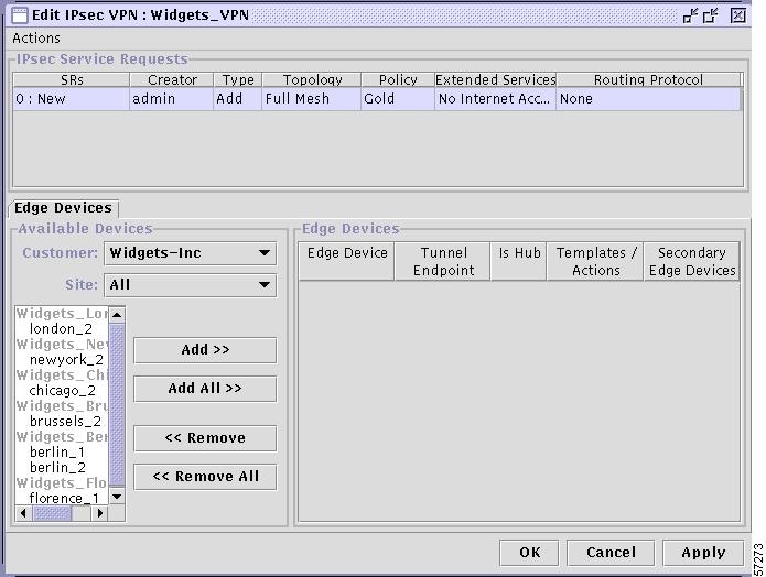
The Edit IPsec VPN dialog box appears (see Figure 5-4).
Figure 5-4 Edit IPsec VPN Dialog Box
Step 1
Figure 5-5 VPN Actions Menu

A new line is displayed in the IPsec Service Requests panel showing the default values for the new service request (see Figure 5-6).
Figure 5-6 Initial Service Request Settings

Step 2
To modify a field, double-click the field and choose the pertinent value from the list.
a.
Choose from Full Mesh or Hub & Spoke.
b.
Choose the appropriate policy name from the list to associate the correct policy with the new service request.
c.
•
This option indicates that the service request provides VPN service only (that is, only secure traffic is allowed between VPN sites). No Internet Access is the default setting.

Caution
•
This option indicates that the service request provides both VPN service and Internet service.
•
This option indicates that the service request provides both VPN service and Internet service. If you enable the Ignore option, VPN Solutions Center does not generate its own ingress ACL. Any existing access control lists on the interface are left intact. The service provider is free to associate any ingress ACL on the router's secured (egress) interface.
If there is no existing ingress ACL associated with the secured interface, the Ignore option serves the same function as the Internet Access option.
Removing devices that are part of a deployed service request does not remove the entire access list that was created by VPN Solutions Center. To remove the access lists that are left out, use the Template Manager or manually remove the left out access list from each removed device.
If there is no access list present on the secured interface before deployment and you want extended service specified as Internet Access, for better performance, specify the Ignore option instead of Internet Access. With Internet Access specified, VPN Solutions Center adds an access list or appends "
IP permit any any" to the existing access list applied to the secured interface.d.
This field provides for exchanging Customer site IP addresses across the current VPN. The default routing protocol setting is None, which indicates that Customer site IP addresses are not exchanged.
To set the Routing Protocol options, click the Routing Protocol field. The Routing Protocol Editor dialog box appears (see Figure 5-7).
Figure 5-7 Setting the Routing Protocol Options

Step 3
a.
If you disable the Generate Default Route option, VPN Solutions Center does not generate a default route for the VPN.
b.
None. If you specify the None option, VPN Solutions Center employs IPsec in Tunnel mode (for more information, see the "Transport Mode and Tunnel Mode" section).
GRE Tunnel Limitation When Using Static Routes
When a service provider uses a Generic Routing Encapsulation (GRE) tunnel provisioned with static routes between two edge device routers—and a secondary device is also configured with a parallel GRE tunnel also using static routes—a limitation in GRE tunnel technology can cause the following problem.
If the tunnel between the primary device and the peer device is down for any reason, the peer device is not notified of the tunnel failure. Its corresponding route remains in the peer devices's routing table, even though the route is no longer in service. As a result, viable traffic continues to be sent along an invalid route (the failed static route from the primary device to the peer device). It is likely that these packets will be lost. The secondary GRE tunnel is never activated.
The only remedy is to manually remove the invalid static route.
Associating the Edge Devices with the Service Request
In this procedure, you associate the edge devices (that is, the sites) with the new service request. You can filter edge devices by Customer or site.
Step 1
Figure 5-8 Defining the Edge Devices in the Service Request

Step 2
Step 3
Step 4
•
The device name is displayed in the Edge Devices panel, which shows additional information, such as the name of the secured interface, whether the device is a hub, and so on.
•
All the device names are displayed in the Edge Devices panel.
Step 5
If you have no additional information to specify, click Apply to activate the service request. Proceed to the "Deploying Service Requests" section.
The service request is now activated. In the IPsec Service Requests panel, the service request is assigned a number and its initial state (usually Requested) is displayed (see Figure 5-8).
Integrating a Template with a Service Request
VPN Solutions Center provides a way to integrate a template with VPNSC configlets. For a given router, you specify the following:
•
•
•
•
•
The template data files are tightly linked with its corresponding template. You can use a data file and its associated template to create a template configuration file. The template configuration file is merged with (either appended to or prepended to) the VPNSC configlet. VPN Solutions Center downloads the combined VPNSC configlet and template configuration file to the edge device router.
You can also download a template configuration file to a router. For details, see the "Provisioning a Template Configuration File Directly to a Router" section.
You can apply the same template to multiple edge devices, assigning the appropriate template data file for each device. Each template data file includes the specific data for a particular device (for example, the management IP address or host name of each device).
To integrate a VPN Solutions Center template with a service request, follow these steps:
Step 1
Step 2
Step 3
Step 4
The Edit IPsec VPN dialog box appears (see Figure 5-9).
Figure 5-9 Edit IPsec VPN Dialog Box

The lower right side of this dialog box is the Edge Devices area. Notice the Templates/Actions column.
Step 5
The Add/Remove Templates dialog box appears.
Selecting a Data File From the Template/Data File Chooser
Step 6
The Template/Data File Chooser dialog box appears (see Figure 5-10).
Figure 5-10 The Template/Data File Chooser Dialog Box

Step 7
The template data files are tightly associated with its corresponding template. You can use a data file and its associated template to create a template configuration file. The template configuration file is merged with (either appended to or prepended to) the VPNSC configlet. VPN Solutions Center downloads the combined configlet to the edge device router.
Step 8
You return to the Add/Remove Templates dialog box (see Figure 5-11).
Determining the Placement and Active Status of the Data File
Figure 5-11 Add/Remove Templates Dialog Box

The Action column in the Add/Remove Templates dialog box lets you specify where the template configuration file is placed in the VPNSC configlet—either prepended or appended.
The Active column lets you determine whether you want the template configuration file to be merged with the VPNSC configlet and downloaded to the target router.
Step 9
•
•
Step 10
•
•
Step 11
Step 12
You return to the Edit IPsec VPN dialog box, where the Templates/Actions field now displays the name of the assigned templates and data files for the designated edge devices (see Figure 5-12).
Figure 5-12 Template Applied to Device

Step 13
The service request is now activated. In the IPsec Service Requests panel, the service request is assigned a number and its initial state (usually Requested) is displayed. The following message is displayed:
All modified SRs successfully updated.
Assigning a Secondary Edge Device
VPN Solutions Center provides a way to assign a secondary edge device in the same site as the primary device. A secondary edge device is a device that can be brought up automatically either for loadsharing or in the event that the primary edge device goes down.
•
The Administrative Distance value for configuring load sharing for the primary device and the specified secondary device is 1.
•
The Administrative Distance value for assigning a secondary device is 10 (which the default).
To assign a secondary edge device, follow these steps:
Step 1
Step 2
Step 3
Step 4
The Edit IPsec VPN dialog box is displayed (see Figure 5-4). The Secondary Edge Devices column is on the far right in the Edge Devices area of the dialog box.
Step 5
The Secondary Devices for Primary Device dialog box appears (see Figure 5-13).
Figure 5-13 Secondary Devices for Primary Device Dialog Box

Step 6
The device is now added to list of secondary edge devices for that site (see Figure 5-14).
Figure 5-14 Secondary Edge Device Added

Step 7
The default Admin Distance is set to 10, which defines the specified device as the device to come up in the event that the primary device goes down.
a.
b.
Step 8
The specified device is now configured in the VPN Solutions Center software as the secondary edge device in that site.
Step 9
The service request is now activated. In the IPsec Service Requests panel, the service request is assigned a number and its initial state (usually Requested) is displayed. The following message is displayed:
All modified SRs successfully updated.
Deploying Service Requests
When the VPN is defined and the service requests for that VPN are activated, you can then deploy the service requests. To deploy service requests, follow these steps:
Step 1
Step 2
The VPN menu is displayed.
Step 3
The Edit IPsec VPN dialog box appears. The upper area of this dialog box is the IPsec Service Requests area (see Figure 5-15).
Figure 5-15 Selecting the Service Request You Want to Deploy
Step 4
Step 5
A dialog box appears, giving you the choice to proceed with the deployment or cancel the operation.
This deployment operation both deploys and audits the selected service request. To view the results, you can bring up the Task Logs by choosing Tools > Task Logs.
Step 6
The Schedule VPN Service dialog box appears (see Figure 5-16).
Figure 5-16 Schedule VPN Service Dialog Box

Step 7
a.
b.
c.
d.
Step 8
The service is added to the Schedule List, displayed in the upper area of the dialog box (as shown in Figure 5-16).
Step 9
You return to the VPN Console. At the bottom of the screen, the following message appears:
All selected SRs successfully scheduled for deployment.

Note
Task Log Error and Warning Messages
If you deploy an invalid service request, VPN Solutions Center generates task logs that say the task completed successfully, but it includes an error message and a warning message. In the task logs, the terms "error" and "warning" are pertinent to the system, not the user.
"Error" indicates that the current process encountered a system error and it cannot run further. Such errors include: database errors, invalid command line parameters, invalid VPN Solutions Center configuration files, disk full, and so on.
"Warning" indicates that the current process did run successfully, but the results are not the expected results.
Redeploying After Changing a Deployed Service Request
When you deploy a service request and then change a provisioning key in the csm.properties file or reconfigure the tunnels on the devices, you can make the change take effect for one or more service requests even if the current service request is already deployed. To do so, follow these steps:
Step 1
Step 2
The VPN menu is displayed.
Step 3
The Edit IPsec VPN dialog box appears. The upper area of this dialog box is the IPsec Service Requests area (see Figure 5-15).
Step 4
Step 5
A dialog box appears, giving you the choice to proceed with the deployment or cancel the operation.
This deployment operation both deploys and audits the selected service request. To view the results, you can bring up the Task Logs by choosing Tools > Task Logs.
Step 6
The Schedule VPN Service dialog box appears (see Figure 5-16).
Step 7
a.
b.
c.
d.
Step 8
The service is added to the Schedule List, displayed in the upper area of the dialog box.
Step 9
Getting Detailed Information on Service Requests
VPN Solutions Center provides a wealth of detailed information about each VPN and service request, such as:
•
•
•
•
You can also deploy a service request from the All IPsec Service Requests Report. To do so, select the pertinent service request from the list, then click the Deploy Service Request button at the bottom of the report.
To view information on a service request, follow these steps:
Step 1
The All IPsec Service Requests Report appears (see Figure 5-17).
Figure 5-17 All IPsec Service Requests Report
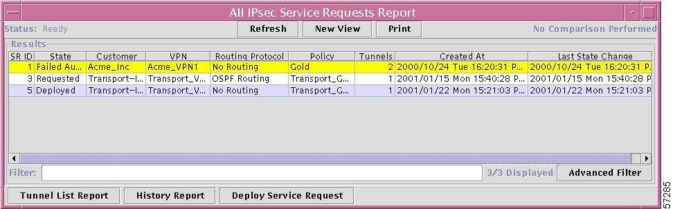
Note
Step 2
The Tunnel List Report
Step 3
Figure 5-18 Tunnel List Report

To return to the previous window, click Back.
Tunnel Details Report
Step 4
The Tunnel Detail Report provides a great deal of information on each tunnel endpoint (see Figure 5-19). If a deployment problem exists, the State is displayed in yellow.
Figure 5-19 Tunnel Details Report

The title bar for the Tunnel Detail Report displays the following information:
•
•
•
For example, Figure 5-19 shows that the tunnel is between the brussels_2 and london_2 edge device routers. The interface on brussels_2 is a FastEthernet0 interface; the interface on london_2 is loopback0 interface.
To return to the previous window, click Back.
Audit Details Report
Step 5
Figure 5-20 IPsec Tunnel Audit Details Report

The IPsec Tunnel Audit Details Report highlights in yellow problems found in the audit.
To return to the previous window, click Back.
History Report
Step 6
a.
b.
c.
The History Report for the selected service appears (see Figure 5-21).
Figure 5-21 History Report

To return to the previous window, click Back.
Closing Service Requests Manually
When you manually close a service request, VPN Solutions Center changes the state of the service to Closed in the Repository. VPNSC does not make any modifications to the router's configuration file when you close a service request. You cannot purge a service request from the Repository until it is closed.
To close a service request, follow these steps:
Step 1
Step 2
Step 3
The menu shown in Figure 5-22 appears.
Figure 5-22 VPN Menu

Step 4
The Edit IPsec VPN dialog box appears (see Figure 5-23).
Figure 5-23 Edit IPsec VPN Dialog Box
Step 5
Step 6
You receive the following confirmation prompt:
Are you sure you want to close the selected service request(s)?
Step 7
To cancel the close operation, click No.
In the IPsec Service Requests area, the request is now displayed as "Closed." VPN Solutions Center changes the state of the selected services to Closed in the Repository.
Removing Service Requests From the Repository
To save disk space and remove extraneous entries in service request reports, you may choose to remove invalid or failed service requests from the Repository. VPN Solutions Center only removes service requests that are in the Closed state.
To remove service requests from the Repository, follow these steps:
Step 1
Step 2
You receive the following confirmation prompt:
All closed service requests will be removed from the database. (There follows additional information on how to close a service request).
Do you want to purge closed service requests now?
Step 3
To cancel the operation, click No.
You receive the following message:
All Closed Requests Purged.
Step 4
The entries for the removed service requests in the Edit IPsec VPN dialog box and in service request reports are also removed.
 Feedback