Supported Line Cards
Cisco Optical Site Manager supports configuration and management of various NCS 1000 cards.
For detailed information about the supported cards, you can refer to the following topics:
The documentation set for this product strives to use bias-free language. For the purposes of this documentation set, bias-free is defined as language that does not imply discrimination based on age, disability, gender, racial identity, ethnic identity, sexual orientation, socioeconomic status, and intersectionality. Exceptions may be present in the documentation due to language that is hardcoded in the user interfaces of the product software, language used based on RFP documentation, or language that is used by a referenced third-party product. Learn more about how Cisco is using Inclusive Language.
This chapter describes the tasks related to provisioning the Cisco NCS 1000 line cards in Cisco Optical Site Manager.

Cisco Optical Site Manager supports configuration and management of various NCS 1000 cards.
For detailed information about the supported cards, you can refer to the following topics:
Use this task to open the card view.
|
Step 1 |
Click COSM Topology in the left panel.. The COSM Topology page appears. |
|
Step 2 |
Right-click the card from the Rack view and select Open Card. Alternatively, you can also double-click the card to open the Card view. |
Use this task to change the admin state of the ports on a card.
|
Step 1 |
Click the tab. |
|
Step 2 |
Click the Pluggable Port Modules section to expand it. The different ports along with their rates, reach distances, and admin states are displayed. |
|
Step 3 |
Click the Edit button. The fields in the table become editable. |
|
Step 4 |
Choose the admin state in the Admin State column from the drop-down list and click Apply. |
Cisco Optical Site Manager allows you to configure NCS 1000 line cards in various modes, including Muxponder and Slice configurations. These modes determine how the line card processes data and manages traffic, facilitating efficient client-to-trunk mapping.
Perform these steps to add a card mode for a line card:
Use this task to enter into the Card Configuration Wizard and select a card mode.

|
Step 1 |
Open the Card Configuration Wizard.
|
||||||
|
Step 2 |
Select the card mode from the drop-down list and click Add.
|
||||||
|
Step 3 |
Click Next. |
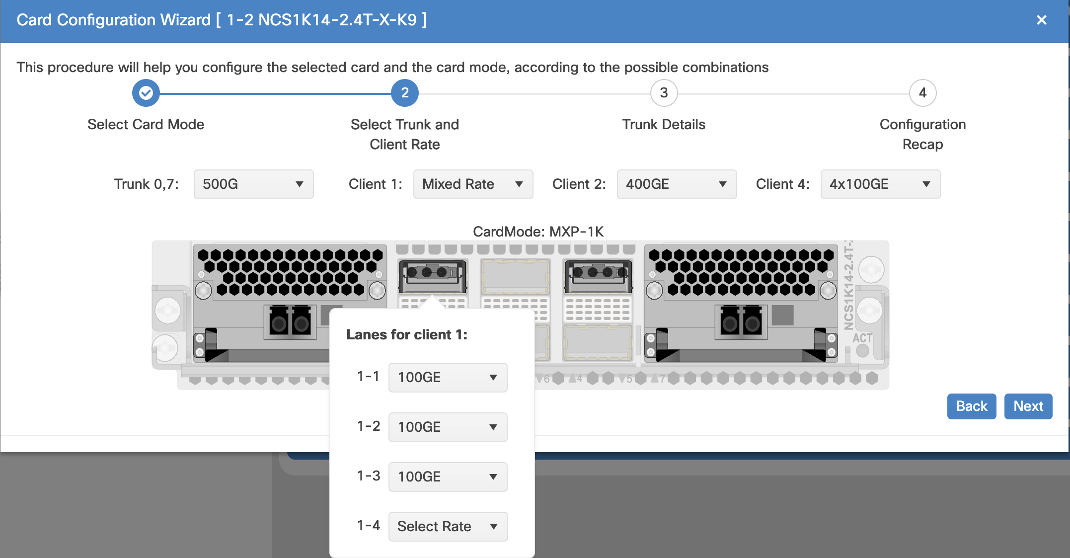
Select the Trunk and Client Data Rates.
Use this task to select the trunk and client port data rates in the Card Configuration Wizard.
|
Step 1 |
Select the trunk data rate from the Trunk drop-down list. |
||||||
|
Step 2 |
Select the client data rates.
|
||||||
|
Step 3 |
Click Next. |
If optical type is configured as txp, see Add Trunk Details.
If optical type is configured as roadm, see Add Internal Patch Cords.
Use this task to add Internal Patch Cords (IPC) in the Card Configuration Wizard.
 Note |
Adding IPC page is only available if optical type is configured as roadm. |

|
Step 1 |
Select the port from the Port drop-down list in the From section. |
||||||
|
Step 2 |
In the To section, perform these steps:
|
||||||
|
Step 3 |
Click the Add button. |
||||||
|
Step 4 |
(Optional) Do one of the following to remove internal patch cord:
|
||||||
|
Step 5 |
Click Next. |
Add the Trunk Details to configure the interfaces.
Use this task to add select the trunk details in the Card Configuration Wizard to configure the interfaces.

If optical type is configured as roadm, make sure to Add Internal Patch Cords
If optical type is configured as txp, make sure to Select Trunk and Client Data Rate
|
Step 1 |
Select the trunk port from the Select trunk for configure the interfaces drop-down list. |
|
Step 2 |
In the Optical Channel section, select the Admin State, Frequency, Baud Rate, Bits Per Symbol and Rate from their corresponding drop-down lists. |
In the Configuration Recap window, verify the selected configuration in the various windows of the Card Configuration Wizard.

|
Step 1 |
Click to expand the Trunk and Client sections to verify the configured details. |
|
Step 2 |
Click Finish to add the card mode. |
Use this task to edit the trunk and client port data rates for a card mode configured on a card.
|
Step 1 |
Open the Card Configuration Wizard using any of these options.
|
|
Step 2 |
Select the trunk and client data rates. For more details about selecting trunk and client data rates, see Select Trunk and Client Data Rate. |
This task allows you to configure the parameters for trail trace monitoring.
|
Step 1 |
Click the tab. |
|||||||||||||||||||||
|
Step 2 |
Click the Trail Trace Monitoring section to expand it. |
|||||||||||||||||||||
|
Step 3 |
From the Level drop-down list, choose Section to list all the OTU interfaces and Path to list all the ODU interfaces. |
|||||||||||||||||||||
|
Step 4 |
Modify required settings as described in the following table.
|
|||||||||||||||||||||
|
Step 5 |
Click Apply. |
|
Step 1 |
Click the tab. |
|||||||||||||||||||||||||||
|
Step 2 |
Click the ODU Interfaces section to expand it. |
|||||||||||||||||||||||||||
|
Step 3 |
Modify required settings described in the following table.
|
|||||||||||||||||||||||||||
|
Step 4 |
Click Apply. |
Use this task to modify the OTU settings of the card.
|
Step 1 |
Click the tab. |
||||||||||||||||||||||||||||||
|
Step 2 |
Click the OTU Interfaces section to expand it. |
||||||||||||||||||||||||||||||
|
Step 3 |
Modify required settings described in the following table.
|
||||||||||||||||||||||||||||||
|
Step 4 |
Click Apply. |
Use this task to provision the parameters for the Ethernet interfaces of the card.
|
Step 1 |
Click the tab. |
|
Step 2 |
Click the Ethernet Interfaces section to expand it. |
|
Step 3 |
Click the Edit button. |
|
Step 4 |
Modify any of the Ethernet settings as described in the following table. These parameters appear depends on the card mode. |
|
Step 5 |
Click Apply. |
|
Parameter |
Description |
Options |
|---|---|---|
|
Port |
(Display only) Displays the port number |
— |
|
Description |
Description of the port. |
— |
|
Speed |
Sets the expected port speed. |
— |
|
MTU |
Sets the maximum size of the Ethernet frames that are accepted by the port. The port must be in OOS/locked state. |
Numeric. Default: 1548 Range 64–9700 |
|
FEC |
Sets the FEC mode. When set to On, FEC is enabled. |
|
|
Duplex |
Sets the expected duplex capability of ports. |
|
|
Mapping |
Sets the mapping mode. |
|
|
Auto Negotiation |
Enables or disables autonegotiation on the port. |
|
|
Squelch Mode |
Sets the squelch mode. |
|
|
Squelch Hold Off Time |
Sets the period in milliseconds that the client interface waits for resolution of issues on the trunk side. The client squelching starts after this period or local fault is sent. |
|
|
Service State |
Displays the service status of the port. |
Use this task to configure the parameters for the optical channels on the card.
|
Step 1 |
Click the tab. |
|||||||||||||||||||||||||||||||||||||||||||||||||||||||
|
Step 2 |
Click the Optical Channel section to expand it. |
|||||||||||||||||||||||||||||||||||||||||||||||||||||||
|
Step 3 |
Click the Edit button and modify required parameters in the table. |
|||||||||||||||||||||||||||||||||||||||||||||||||||||||
|
Step 4 |
Click Apply. This table describes the parameters displayed in the Optical Channel section.
|
You can directly change the trunk port parameters from the Rack, Chassis, or Card view. These parameter values can then be viewed in the Optical Channel section of the Provisioning tab.
Use this task to configure the trunk port parameters, such as admin state, frequency, baud rate, and bits per symbol.
|
Step 1 |
Right-click the trunk ports in the Rack, Chassis, or Card view and click Change Trunk Details. |
|
Step 2 |
Select the Admin State to change the admin status of the trunk port to Out of Service or Automatic in Service. |
|
Step 3 |
Enter or select the frequency in the Frequency field. The Wavelength of the trunk port is automatically selected based on the frequency configured. |
|
Step 4 |
Enter or select the Baud Rate or Bits Per Symbol. For more details about these fields, see the table Table 1 |
|
Step 5 |
Click Apply. |
Use this task to set the threshold crossing alert values on the card.
|
Step 1 |
Click the tab. |
|
Step 2 |
Click the Optics Thresholds section to expand it. |
|
Step 3 |
Choose the type of threshold that you want to change, 15 Min or 24 Hour. |
|
Step 4 |
Click Add Optical Threshold button. |
|
Step 5 |
In the New Optical Threshold dialog box, add these details: |
|
Step 6 |
Click Apply. |
Use this task to provision the G.709 PM thresholds for the OTN ports.
|
Step 1 |
Click the tab. |
||||||||||||
|
Step 2 |
Click the G.709 Thresholds section to expand it. |
||||||||||||
|
Step 3 |
Choose the value for the G.709 PM thresholds, and click Apply. You can set the thresholds for Near End or Far End, for 15 minutes or 1 day intervals, or for SM (OTUk) or PM (ODUk).
|
Use this task to provision the FEC thresholds for the card.
|
Step 1 |
Click the tab. |
|
Step 2 |
Click the FEC Thresholds section to expand it. |
|
Step 3 |
Choose the value for the FEC PMs and click Apply. You can set the FEC thresholds for 15 minutes or one-day intervals. The possible PM types are:
|
Use this task to provision the RMON thresholds on the control card.
|
Step 1 |
Click the tabs. |
|
Step 2 |
Click the + button. The Create RMON Threshold dialog box appears. |
|
Step 3 |
From the Port ID drop-down list, choose the port number. |
|
Step 4 |
From the Variable drop-down list, choose a variable. |
|
Step 5 |
From the Alarm Type drop-down list, indicate whether the event is triggered by the rising threshold, falling threshold, or both thresholds. The available options are Rising Threshold, Falling Threshold, and Rising and Falling Threshold. |
|
Step 6 |
From the Sampling Type drop-down list, choose either Relative or Absolute. Relative restricts the threshold to use the number of occurrences within the user-set sample period. Absolute sets the threshold to use the total number of occurrences, regardless of the time period. |
|
Step 7 |
Enter the appropriate number of seconds in the Sampling Period field. |
|
Step 8 |
Enter the appropriate number of occurrences in the Rising Threshold field. For a rising type of alarm, the measured value must move from below the falling threshold to above the rising threshold. For example, if a network is running below a rising threshold of 1000 collisions every 15 seconds and a problem causes 1001 collisions in 15 seconds, the excess occurrences trigger an alarm. |
|
Step 9 |
Enter the appropriate number of occurrences in the Falling Threshold field. In most cases, a falling threshold is set lower than the rising threshold. |
|
Step 10 |
Click Apply. |
Use this task to provision loopback on the card.
 Caution |
This task is traffic-affecting. |
Perform the loopback configuration only in the maintenance service state. To place the trunk ports in the Locked, maintenance state, see Provision Optical Channels.
|
Step 1 |
Click the tab. |
|
Step 2 |
Click the Loopback section to expand it. |
|
Step 3 |
From the Loopback Type drop-down list, choose Terminal, Facility, Terminal-Drop, or Facility-Drop for each port required. |
|
Step 4 |
Select the admin state from the Admin State drop-down list. |
|
Step 5 |
Click Apply. |
Use this task to provision the optical safety parameters for cards.
|
Step 1 |
Click the tab. |
|||||||||||||||||||||||||||||
|
Step 2 |
Click the Live Data section to expand it. |
|||||||||||||||||||||||||||||
|
Step 3 |
Modify required settings described in the following table:
|
|||||||||||||||||||||||||||||
|
Step 4 |
Click Apply to save the changes. |
 Feedback