- Preface
- Chapter 1, Introduction
- Chapter 2, Creating and Analyzing Networks
- Chapter 3, Viewing Network Reports
- Chapter 4, Editing Projects
- Chapter 5, Modeled Network Examples
- Appendix A, GUI Information and Shortcuts
- Appendix B, Card Types
- Appendix C, System Messages
- Appendix D, Third-Party DWDM Wavelength Interface Model
- Appendix E, Configuring CTP to Run on a Server
Cisco Transport Planner DWDM Operations Guide Release 9.0
Bias-Free Language
The documentation set for this product strives to use bias-free language. For the purposes of this documentation set, bias-free is defined as language that does not imply discrimination based on age, disability, gender, racial identity, ethnic identity, sexual orientation, socioeconomic status, and intersectionality. Exceptions may be present in the documentation due to language that is hardcoded in the user interfaces of the product software, language used based on RFP documentation, or language that is used by a referenced third-party product. Learn more about how Cisco is using Inclusive Language.
- Updated:
- March 20, 2015
Chapter: Chapter 4, Editing Projects
- 4.1 Editing Project Parameters
- 4.2 Editing Network Parameters
- 4.3 Editing Site Parameters
- 4.4 Editing Service Demand Association and Traffic Subnet
- 4.5 Creating a Maintenance Center
- 4.6 Editing a Point-to-Point Demand
- 4.7 Editing a P-Ring Demand
- 4.8 Editing a ROADM Demand
- 4.9 Editing an Ethernet Aggregated Demand
- 4.10 Editing a TDM Aggregated Demand
- 4.11 Editing Fiber Span, Pair, and Fiber Parameters
- 4.12 Editing Fiber Spans, Pairs, and Fibers Using the Fibres Dialog Box
- 4.13 Rack Rules
- 4.14 Shelf Rules
- 4.15 Adjusting Site Layout
- 4.16 Arranging Sites
- 4.17 Modifying Site Structure, Functionality, and Type
- 4.18 Deleting Notes
- 4.19 Deleting Sites
- 4.20 Deleting a Traffic Demand
- 4.21 Deleting a Traffic Subnet
- 4.22 Deleting a Fiber Span
- 4.23 Deleting a Network
Editing a Project
Cisco Transport Planner allows you to edit the a project either before or after network analysis. Error messages that occur during network analysis often cannot be resolved until you edit one or more network components.
To complete the procedures in this section, you must have a project open and the network(s) loaded. See the "1.4.1 Opening a Project" section on page 1-15 and the "1.4.2 Loading and Unloading Networks" section on page 1-16.
4.1 Editing Project Parameters
Use the following procedure to edit project parameters:
Step 1 ![]() Click Project in the Project Explorer.
Click Project in the Project Explorer.
Step 2 ![]() In the Properties pane, complete the following tasks as needed:
In the Properties pane, complete the following tasks as needed:
•![]() Customer—Enter the name of the customer (128-character maximum) requiring this network design.
Customer—Enter the name of the customer (128-character maximum) requiring this network design.
•![]() Created by—Enter the user name (128-character maximum).
Created by—Enter the user name (128-character maximum).
•![]() Units—Displays the span measurement unit: Km (kilometers) or Miles.
Units—Displays the span measurement unit: Km (kilometers) or Miles.
•![]() Price List—Choose the price database from the drop-down list.
Price List—Choose the price database from the drop-down list.
•![]() Layout—Displays ANSI (the North American standard) or ETSI (the international standard) to indicate the platform type. ANSI networks do not allow you to define SDH (ETSI) service demands. ETSI networks do not allow you to define SONET (ANSI) service demands.
Layout—Displays ANSI (the North American standard) or ETSI (the international standard) to indicate the platform type. ANSI networks do not allow you to define SDH (ETSI) service demands. ETSI networks do not allow you to define SONET (ANSI) service demands.
4.2 Editing Network Parameters
Use the following procedure to edit network parameters:
Step 1 ![]() Click a network in the Project Explorer or Mgmt Tree.
Click a network in the Project Explorer or Mgmt Tree.
Step 2 ![]() In the Properties pane, complete the following tasks as needed:
In the Properties pane, complete the following tasks as needed:
•![]() Name—Enter the network name (128-character maximum).
Name—Enter the network name (128-character maximum).
•![]() Position—Enter the object location in pixels.
Position—Enter the object location in pixels.
•![]() Created by—Enter the user name (128-character maximum).
Created by—Enter the user name (128-character maximum).
•![]() Status—Displays the state of the network (Design, Design-Analyzed, Install, and so on).
Status—Displays the state of the network (Design, Design-Analyzed, Install, and so on).
•![]() Use MSM Bundles—Check to use the Multishelf Management Integrated Kit bundle when generating the BoM instead of the single items.
Use MSM Bundles—Check to use the Multishelf Management Integrated Kit bundle when generating the BoM instead of the single items.
•![]() Use Spare Parts—Check to determine the spare parts required by the network. If the network is in the Upgrade state, the parts required to support the implemented services and the newly added present services are included. To generate a spare parts report, you must associate the sites in a network with a maintenance center before network analysis.
Use Spare Parts—Check to determine the spare parts required by the network. If the network is in the Upgrade state, the parts required to support the implemented services and the newly added present services are included. To generate a spare parts report, you must associate the sites in a network with a maintenance center before network analysis.
•![]() Use Global Discount—Check to use the global discount for the entire network. The global discount is applied to all components in the BoM.
Use Global Discount—Check to use the global discount for the entire network. The global discount is applied to all components in the BoM.
•![]() Global Discount—Enter a new global discount in the form of a percentage.
Global Discount—Enter a new global discount in the form of a percentage.
•![]() Service Level—Choose the service level (contract) identifier from the drop-down list.
Service Level—Choose the service level (contract) identifier from the drop-down list.
•![]() Service Length—Choose the maintenance service level length (in years) from the drop-down list.
Service Length—Choose the maintenance service level length (in years) from the drop-down list.
•![]() Include SW Licenses—Check to include software licenses in the BoM.
Include SW Licenses—Check to include software licenses in the BoM.
•![]() Include Paper Documentation—Check to include paper documentation in the BoM.
Include Paper Documentation—Check to include paper documentation in the BoM.
•![]() Include CD Documentation—Check to include CD documentation in the BoM.
Include CD Documentation—Check to include CD documentation in the BoM.
•![]() Hide Bom/price discount—Check to hide the global discount in the Unit Price column of the BoM.
Hide Bom/price discount—Check to hide the global discount in the Unit Price column of the BoM.
•![]() Dimension—Enter the network size in pixels.
Dimension—Enter the network size in pixels.
•![]() Background color—Click to choose a color for the network background.
Background color—Click to choose a color for the network background.
•![]() Background image—Displays the JPEG or GIF filename used as a background, if any. To choose a JPEG or GIF file as a background graphic for the network, click the down arrow and navigate to the desired directory.
Background image—Displays the JPEG or GIF filename used as a background, if any. To choose a JPEG or GIF file as a background graphic for the network, click the down arrow and navigate to the desired directory.
4.3 Editing Site Parameters
Editing the site parameters allows you to make changes to the current site configuration. A site folder in the Project Explorer displays the interface node information. Each site contains an NEs folder in which network elements (NEs) are placed. The NEs are created after the network analysis.
The following configurations result in more than one NE creation:
•![]() Individual shelf with OIC site functionality: One NE for each side.
Individual shelf with OIC site functionality: One NE for each side.
•![]() Individual shelf: One NE for each shelf.
Individual shelf: One NE for each shelf.
•![]() Multishelf with line card: One NE and one NE for each line card shelf.
Multishelf with line card: One NE and one NE for each line card shelf.
Modifications in the site structure, functionality, and type also modify the number of NEs created.
Figure 4-1 shows a site in the Project Explorer before network analysis. Figure 4-2 shows a site in the Project Explorer after network analysis.
Figure 4-1 Site in the Project Explorer

Figure 4-2 Analyzed Site in the Project Explorer

A site folder for an analyzed network design also contains the following items, many of which you can edit:
•![]() A and B—For a Line or Line+ site, two interface nodes appear in the Project Explorer under the Site folder, labeled A and B. For a Terminal or Terminal+ site, only one interface node (A) appears.
A and B—For a Line or Line+ site, two interface nodes appear in the Project Explorer under the Site folder, labeled A and B. For a Terminal or Terminal+ site, only one interface node (A) appears.
•![]() Aw and Ap—For a PSM Terminal Optical Path site or a PSM Terminal Multiple Section site, two interface sides appear in the Project Explorer pane under the Site folder, labeled Aw and Ap. Aw represents the working path and Aw represents the protection path.
Aw and Ap—For a PSM Terminal Optical Path site or a PSM Terminal Multiple Section site, two interface sides appear in the Project Explorer pane under the Site folder, labeled Aw and Ap. Aw represents the working path and Aw represents the protection path.
For a PSM Terminal Optical Path site, the following options are available under the supported bands for the two interfaces. See Figure 4-3.
–![]() For Aw: Amplifiers, Add/Drop, and DWDM protection
For Aw: Amplifiers, Add/Drop, and DWDM protection
–![]() For Ap: DWDM protection
For Ap: DWDM protection
For a PSM Terminal Multiple Section site, the following options are available under the supported bands for the two interfaces. See Figure 4-4.
–![]() For Aw: Amplifiers, Add/Drop, and DWDM protection
For Aw: Amplifiers, Add/Drop, and DWDM protection
–![]() For Ap: Amplifiers and DWDM protection
For Ap: Amplifiers and DWDM protection
Figure 4-3 PSM Terminal Optical Path Site in the Project Explorer

Figure 4-4 PSM Terminal Multiple Section Site in Project Explorer

•![]() C-Band or L-Band—Displays the supported band for the sides.
C-Band or L-Band—Displays the supported band for the sides.
•![]() Amplifiers—Lists the amplifiers and all related cards for each band and for each side.
Amplifiers—Lists the amplifiers and all related cards for each band and for each side.
•![]() Add/Drop—Displays all of the add/drop and related cards for the band and side.
Add/Drop—Displays all of the add/drop and related cards for the band and side.
•![]() Site Type Parameters—When selected, shows the site functionality and type in the Properties pane.
Site Type Parameters—When selected, shows the site functionality and type in the Properties pane.
•![]() Band Parameters—When selected, shows the output power in the Properties pane.
Band Parameters—When selected, shows the output power in the Properties pane.
•![]() Client—Lists the client cards.
Client—Lists the client cards.
Use the following procedure to edit site parameters. To delete a site, see the "Deleting Sites" section.
Step 1 ![]() In the Project Explorer, right-click the network folder and choose Expand from the shortcut menu.
In the Project Explorer, right-click the network folder and choose Expand from the shortcut menu.
Step 2 ![]() Click the desired Site folder. The site parameters appear in the Properties pane.
Click the desired Site folder. The site parameters appear in the Properties pane.
Step 3 ![]() Complete the following tasks to modify the site parameters in the Properties pane, as needed:
Complete the following tasks to modify the site parameters in the Properties pane, as needed:

Note ![]() You cannot edit the site structure parameter of the PSM sites. You can only choose A/D functionality with Mux/Demux type or ROADM functionality with WSS type for the PSM sites.
You cannot edit the site structure parameter of the PSM sites. You can only choose A/D functionality with Mux/Demux type or ROADM functionality with WSS type for the PSM sites.
•![]() Name—Enter the desired site name.
Name—Enter the desired site name.
•![]() Position—Enter the desired site pixel position; for example, an entry of 0,0 positions the Site icon in the upper-left corner of the NtView Name tab.
Position—Enter the desired site pixel position; for example, an entry of 0,0 positions the Site icon in the upper-left corner of the NtView Name tab.
•![]() Structure—Choose the structure type from the drop-down list:
Structure—Choose the structure type from the drop-down list:
–![]() Line—Two pairs of fibers are terminated at the node.
Line—Two pairs of fibers are terminated at the node.
–![]() Terminal—A single pair of fibers is terminated at the node.
Terminal—A single pair of fibers is terminated at the node.
–![]() Line+—Two pairs of fibers are terminated at the node, but the number of fibers can be increased when an MMU card (topology upgrade) is installed. This node is ready to scale to become a multidegree node after MMUs are installed in this node.
Line+—Two pairs of fibers are terminated at the node, but the number of fibers can be increased when an MMU card (topology upgrade) is installed. This node is ready to scale to become a multidegree node after MMUs are installed in this node.
–![]() Terminal+—A single pair of fibers is terminated at the node, but the number of fibers can be increased if an MMU card (topology upgrade) is installed. This node is ready to scale to become a multidegree node after MMUs are installed in this node.
Terminal+—A single pair of fibers is terminated at the node, but the number of fibers can be increased if an MMU card (topology upgrade) is installed. This node is ready to scale to become a multidegree node after MMUs are installed in this node.
–![]() Multi-degree—Nodes have more than two sides and faces more than two fiber spans.
Multi-degree—Nodes have more than two sides and faces more than two fiber spans.
Note ![]() You can mark the side of a multi-degree OXC site as an omni-directional entry point by checking the Omnidir Entry Point option in the Properties page for the selected side. Traffic will not be added or dropped at the marked side and OSC units will not be allowed. A side with the Omnidir Entry Point property enabled can be connected only to a Terminal site. Traffic from the Terminal site is directed towards a side not having the omnidirectional property. You cannot create a service demand between the Terminal site connected to the OXC through the omnidirectional side. Traffic directed to the OXC site is terminated on the sides without the omnidirectional property.
You can mark the side of a multi-degree OXC site as an omni-directional entry point by checking the Omnidir Entry Point option in the Properties page for the selected side. Traffic will not be added or dropped at the marked side and OSC units will not be allowed. A side with the Omnidir Entry Point property enabled can be connected only to a Terminal site. Traffic from the Terminal site is directed towards a side not having the omnidirectional property. You cannot create a service demand between the Terminal site connected to the OXC through the omnidirectional side. Traffic directed to the OXC site is terminated on the sides without the omnidirectional property.
The following structure edits are allowed:
–![]() Line to Line+
Line to Line+
–![]() Line+ to Line
Line+ to Line
–![]() Terminal to Terminal+
Terminal to Terminal+
–![]() Terminal+ to Terminal
Terminal+ to Terminal
Note ![]() You cannot edit the structure parameter of intermediate sites, on both the working and protected sides, in a PSM Line or PSM Section network topology.
You cannot edit the structure parameter of intermediate sites, on both the working and protected sides, in a PSM Line or PSM Section network topology.
To make any other structure change (such as changing from Line to Terminal), you must delete and reinsert the site.
•![]() MTTR (hours)—Enter the mean time to repair (MTTR) for all sites in the network. This value will apply to every site in the network. If you change the MTTR value after creating sites, the new value will only apply to sites you create after the change.
MTTR (hours)—Enter the mean time to repair (MTTR) for all sites in the network. This value will apply to every site in the network. If you change the MTTR value after creating sites, the new value will only apply to sites you create after the change.
•![]() Maintenance Center—Choose the name of the maintenance center from the drop-down list. To create a maintenance center, see the "Creating a Maintenance Center" section.
Maintenance Center—Choose the name of the maintenance center from the drop-down list. To create a maintenance center, see the "Creating a Maintenance Center" section.
•![]() IP Address—Type the IP address of the node.
IP Address—Type the IP address of the node.
•![]() Shelf Config—Choose the shelf configuration type from the drop-down list:
Shelf Config—Choose the shelf configuration type from the drop-down list:
–![]() Multi Shelf Integrated Switch—All the MSTP optical cards (OADMs and amplifiers) reside in different shelves connected by a LAN. The LAN is implemented with switches connected to the MSTP shelves. For this option, Multi-Shelf Integrated Switch Cards (MS-ISC) are used to support the multishelf configuration.
Multi Shelf Integrated Switch—All the MSTP optical cards (OADMs and amplifiers) reside in different shelves connected by a LAN. The LAN is implemented with switches connected to the MSTP shelves. For this option, Multi-Shelf Integrated Switch Cards (MS-ISC) are used to support the multishelf configuration.
–![]() Multi Shelf External Switch—All the MSTP optical cards (OADMs and amplifiers) reside in different shelves connected by a LAN. The LAN is implemented with switches external to the MSTP shelves. For this option, two external Ethernet switch units are used to support the multishelf configuration.
Multi Shelf External Switch—All the MSTP optical cards (OADMs and amplifiers) reside in different shelves connected by a LAN. The LAN is implemented with switches external to the MSTP shelves. For this option, two external Ethernet switch units are used to support the multishelf configuration.
–![]() Individual Shelf—All the MSTP optical cards (OADMs and amplifiers) reside in the same shelf. For this option, multishelf management is not supported; every shelf is managed as an independent shelf.
Individual Shelf—All the MSTP optical cards (OADMs and amplifiers) reside in the same shelf. For this option, multishelf management is not supported; every shelf is managed as an independent shelf.
Note ![]() If you chose Individual Shelf as the Shelf Management type, n Network Elements (NEs) will be created where n is the number of shelves. If you chose Multishelf as the Shelf Management type, all subtended shelves will belong to a single NE. The network elements are created after network analysis.
If you chose Individual Shelf as the Shelf Management type, n Network Elements (NEs) will be created where n is the number of shelves. If you chose Multishelf as the Shelf Management type, all subtended shelves will belong to a single NE. The network elements are created after network analysis.
•![]() Node Protection—Choose the node protection type from the drop-down list: Same Shelf or Separated Shelves.
Node Protection—Choose the node protection type from the drop-down list: Same Shelf or Separated Shelves.
•![]() DCC Shelves Management—When checked, indicates that a TXP(P)_MR_2.5G card is in Slot 12 on each shelf at each site.
DCC Shelves Management—When checked, indicates that a TXP(P)_MR_2.5G card is in Slot 12 on each shelf at each site.
•![]() TXP/MXP OSMINE placement—When checked, indicates that the transponder/muxponder cards are placed in the shelves according to OSMINE placement rules.
TXP/MXP OSMINE placement—When checked, indicates that the transponder/muxponder cards are placed in the shelves according to OSMINE placement rules.
•![]() Hybrid MSTP/MSPP Node—When checked, indicates that all the nodes are configured as hybrid MSTP/MSPP nodes.
Hybrid MSTP/MSPP Node—When checked, indicates that all the nodes are configured as hybrid MSTP/MSPP nodes.
•![]() Max Number of Shelves/Bay—Choose the maximum number (from 1 to 4) of ANSI or ETSI shelves (that equip optical cards or transponder/muxponder cards) that can be placed in each rack in the site when generating the site layout.
Max Number of Shelves/Bay—Choose the maximum number (from 1 to 4) of ANSI or ETSI shelves (that equip optical cards or transponder/muxponder cards) that can be placed in each rack in the site when generating the site layout.
•![]() Functionality—Displays the site functionality. To edit this field, double-click the site in the network view. The Edit dialog box appears. Choose the site functionality from the drop-down list. Table 4-1 summarizes the site design rules. The site icon changes depending on the functionality. For a description of the site icons, see Appendix A, "GUI Information and Shortcuts."
Functionality—Displays the site functionality. To edit this field, double-click the site in the network view. The Edit dialog box appears. Choose the site functionality from the drop-down list. Table 4-1 summarizes the site design rules. The site icon changes depending on the functionality. For a description of the site icons, see Appendix A, "GUI Information and Shortcuts."
Note ![]() You can choose only the following options for the functionality parameter of intermediate sites (on both the working and protected sides) in a PSM Line or PSM Section network topology:
You can choose only the following options for the functionality parameter of intermediate sites (on both the working and protected sides) in a PSM Line or PSM Section network topology:
PSM Section: Pass Through or Line Amplifier
PSM Line: Pass Through
–![]() Auto—Allows the highest degree of flexibility in creating the network. Cisco Transport Planner generates a design for the site with the lowest possible cost given the other constraints.
Auto—Allows the highest degree of flexibility in creating the network. Cisco Transport Planner generates a design for the site with the lowest possible cost given the other constraints.
–![]() Pass Through—Indicates that no equipment will be located at this site.
Pass Through—Indicates that no equipment will be located at this site.
–![]() Line amplifier—Prevents any add/drop traffic at this site.
Line amplifier—Prevents any add/drop traffic at this site.
–![]() OSC site—Indicates that site is designated for network communication, providing the possibility to access the OSC for management of the MSTP network. By default, no amplifiers are included in this site. However, if Cisco Transport Planner determines that an amplifier is required in the network, it can automatically place it at this location. Cisco Transport Planner allows you to set (force) preamplifier and booster amplifiers for each direction on a OSC site node.
OSC site—Indicates that site is designated for network communication, providing the possibility to access the OSC for management of the MSTP network. By default, no amplifiers are included in this site. However, if Cisco Transport Planner determines that an amplifier is required in the network, it can automatically place it at this location. Cisco Transport Planner allows you to set (force) preamplifier and booster amplifiers for each direction on a OSC site node.
–![]() Add/Drop—Indicates that this site has add/drop capability. Only point-to-point and P-ring circuits can be added/dropped at this site.
Add/Drop—Indicates that this site has add/drop capability. Only point-to-point and P-ring circuits can be added/dropped at this site.
–![]() Hub—Indicates that this site is equipped with filters for adding and dropping all the channels (on both West and East sides). All express paths are open in hub configurations.
Hub—Indicates that this site is equipped with filters for adding and dropping all the channels (on both West and East sides). All express paths are open in hub configurations.
–![]() Gain equalizer—Indicates that this site uses WSS cards to control the generated tilt and extend unregenerated distances. The site is realized as an ROADM site without demultiplexer cards.
Gain equalizer—Indicates that this site uses WSS cards to control the generated tilt and extend unregenerated distances. The site is realized as an ROADM site without demultiplexer cards.
–![]() R-OADM—Indicates that this site supports Any-to-Any and also Fixed (point-to-point and P-ring) traffic types.
R-OADM—Indicates that this site supports Any-to-Any and also Fixed (point-to-point and P-ring) traffic types.
–![]() OXC—Indicates that this site uses OXC (optical cross connect) cards to control the generated tilt and extend unregenerated distances. This site is realized as an ROADM site without demultiplexer cards.
OXC—Indicates that this site uses OXC (optical cross connect) cards to control the generated tilt and extend unregenerated distances. This site is realized as an ROADM site without demultiplexer cards.
–![]() OIC—Indicates that this site uses OIC (optical inter connect) cards to control the generated tilt and extend unregenerated distances. This site is realized as an ROADM site without demultiplexer cards.
OIC—Indicates that this site uses OIC (optical inter connect) cards to control the generated tilt and extend unregenerated distances. This site is realized as an ROADM site without demultiplexer cards.
Note ![]() This functionality is available only for multi-degree sites. Also, if you choose the structure of a site as multi-degree and functionality as OXC, the Shelf Management option that you select should either be Integrated or External. Otherwise, the application displays an error message when analyzed.
This functionality is available only for multi-degree sites. Also, if you choose the structure of a site as multi-degree and functionality as OXC, the Shelf Management option that you select should either be Integrated or External. Otherwise, the application displays an error message when analyzed.
•![]() Type—Displays the site type. To edit this field, double-click the site in the network view. The Edit dialog box appears. Choose the site type from the drop-down list (see Table 4-1):
Type—Displays the site type. To edit this field, double-click the site in the network view. The Edit dialog box appears. Choose the site type from the drop-down list (see Table 4-1):
–![]() Auto—Allows the highest degree of flexibility in creating the network. Cisco Transport Planner generates a design for the site with the lowest possible cost given the other set of constraints.
Auto—Allows the highest degree of flexibility in creating the network. Cisco Transport Planner generates a design for the site with the lowest possible cost given the other set of constraints.
–![]() Glass Through—Indicates a low-priority amplification site.
Glass Through—Indicates a low-priority amplification site.
–![]() Line—Indicates a high-priority amplification site.
Line—Indicates a high-priority amplification site.
–![]() OADM—Indicates that it is a site with add/drop channels using discrete channel filters (1, 2, 4-ch 1, 4-band).
OADM—Indicates that it is a site with add/drop channels using discrete channel filters (1, 2, 4-ch 1, 4-band).
–![]() 32-WSS—Indicates that it is a site equipped with 32DMX or 32DMX-O. This option allows you to force the use of specific ROADM units.
32-WSS—Indicates that it is a site equipped with 32DMX or 32DMX-O. This option allows you to force the use of specific ROADM units.
Note ![]() 32-WSS is available as choice in system release 7.0.x and above.
32-WSS is available as choice in system release 7.0.x and above.
–![]() Mux/Demux—Indicates that this is a full multiplexer/demultiplexer (FMD) site that adds and drops all channels on both sides using the 32MUX-O and 32DMX-O cards. Optical bypass is allowed.
Mux/Demux—Indicates that this is a full multiplexer/demultiplexer (FMD) site that adds and drops all channels on both sides using the 32MUX-O and 32DMX-O cards. Optical bypass is allowed.
–![]() 40-WXC w/PP-MESH-4—(Multi-degree OXC sites only) Indicates the mesh type that is provided for sites equipped with 40-WXC cards. If this type is selected, the site will be equipped to support up to 4 degrees independently of the number of fibers connected to the site.
40-WXC w/PP-MESH-4—(Multi-degree OXC sites only) Indicates the mesh type that is provided for sites equipped with 40-WXC cards. If this type is selected, the site will be equipped to support up to 4 degrees independently of the number of fibers connected to the site.
–![]() 40-WXC w/PP-MESH-8—(Multi-degree OXC sites only) Indicates the mesh type that is provided for sites equipping 40-WXC cards units. If this type is selected, the site will be equipped support up to 8 degrees independently of the number of fibers connected to the site.
40-WXC w/PP-MESH-8—(Multi-degree OXC sites only) Indicates the mesh type that is provided for sites equipping 40-WXC cards units. If this type is selected, the site will be equipped support up to 8 degrees independently of the number of fibers connected to the site.
–![]() WSS/DMX—Multi-degree OIC sites only.
WSS/DMX—Multi-degree OIC sites only.
•![]() Anti ASE—Choose Yes to configure the site so that all the express channels on the site are optically dropped and reinserted. In addition, all the patch cords between the West and East sections are removed. Choose Auto to allow Cisco Transport Planner to decide if the site should be configured as anti-amplified spontaneous emissions (anti-ASE). See Table 4-1 for a summary of the site design rules.
Anti ASE—Choose Yes to configure the site so that all the express channels on the site are optically dropped and reinserted. In addition, all the patch cords between the West and East sections are removed. Choose Auto to allow Cisco Transport Planner to decide if the site should be configured as anti-amplified spontaneous emissions (anti-ASE). See Table 4-1 for a summary of the site design rules.
Step 4 ![]() To modify the band parameters, click C-Band or L-Band in the Project Explorer for the desired site interface. In the Properties pane, enter the desired Output power.
To modify the band parameters, click C-Band or L-Band in the Project Explorer for the desired site interface. In the Properties pane, enter the desired Output power.
Step 5 ![]() To modify amplifier parameters, click C-Band Amplifiers or L-Band Amplifiers in the Project Explorer for the desired site interface. Choosing a value other than Auto will force a setting on the unit. For more information, see the "1.1.6 Auto, Forced, and Locked Parameters" section on page 1-12.
To modify amplifier parameters, click C-Band Amplifiers or L-Band Amplifiers in the Project Explorer for the desired site interface. Choosing a value other than Auto will force a setting on the unit. For more information, see the "1.1.6 Auto, Forced, and Locked Parameters" section on page 1-12.
a. ![]() In the Properties pane From Fibre area, complete the following as needed:
In the Properties pane From Fibre area, complete the following as needed:
•![]() PRE—Choose the desired preamplifier from the drop-down list (None, Auto, OPT-PRE [C-band], OPT-AMP-C [C-band], or OPT-AMP-L [L-band]).
PRE—Choose the desired preamplifier from the drop-down list (None, Auto, OPT-PRE [C-band], OPT-AMP-C [C-band], or OPT-AMP-L [L-band]).
Note ![]() If Raman amplification is enabled, the amplifier in the From Fibre area can be OPT-AMP -C, OPT-AMP-17, OPT-BST or OPT-BST-E.
If Raman amplification is enabled, the amplifier in the From Fibre area can be OPT-AMP -C, OPT-AMP-17, OPT-BST or OPT-BST-E.
•![]() DCU 1/2—Choose the desired DCU from the drop-down lists.
DCU 1/2—Choose the desired DCU from the drop-down lists.
•![]() Attenuator—Choose the desired attenuator from the drop-down list.
Attenuator—Choose the desired attenuator from the drop-down list.
•![]() Output power—Enter the desired output power.
Output power—Enter the desired output power.
•![]() Tilt—Enter the desired tilt value.
Tilt—Enter the desired tilt value.
•![]() Attenuator—Choose the attenuator from the drop-down list.
Attenuator—Choose the attenuator from the drop-down list.
b. ![]() In the Properties pane To Fibre area, complete the following tasks as needed:
In the Properties pane To Fibre area, complete the following tasks as needed:
•![]() BST—Choose the desired booster from the drop-down list (None, Auto, OPT-BST [C-band], OPT-BST-E [C-band], OPT-AMP-L [L-band], or OPT-BST-L [L-band]).
BST—Choose the desired booster from the drop-down list (None, Auto, OPT-BST [C-band], OPT-BST-E [C-band], OPT-AMP-L [L-band], or OPT-BST-L [L-band]).
Note ![]() If Raman amplification is enabled, the amplifier in the To Fibre area can be OPT-AMP -C, OPT-BST, or OPT-BST-E.
If Raman amplification is enabled, the amplifier in the To Fibre area can be OPT-AMP -C, OPT-BST, or OPT-BST-E.
•![]() DCU 1/2—Choose the desired DCUs from the drop-down lists.
DCU 1/2—Choose the desired DCUs from the drop-down lists.
•![]() Output power—Enter the desired output power.
Output power—Enter the desired output power.
•![]() Tilt—Enter the desired tilt value.
Tilt—Enter the desired tilt value.
c. ![]() In the Properties pane General area, choose the OSC from the drop-down list (OSC-CSM or OSCM).
In the Properties pane General area, choose the OSC from the drop-down list (OSC-CSM or OSCM).
d. ![]() In the Properties pane Raman Amplification area, complete the following tasks as needed. See Figure 4-6:
In the Properties pane Raman Amplification area, complete the following tasks as needed. See Figure 4-6:
•![]() RAMAN—Choose the card from the drop-down list.
RAMAN—Choose the card from the drop-down list.
Note ![]() A Raman amplifier must not be placed on a pass through site. For example, in Figure 4-5, site 1 is a pass-through site. The algorithm treats the span between site 3 and site 1 and the span between site 1 and site 2 as one span and places the Raman amplifier on the external sites (site 2 and site 3) on the ends of the span.
A Raman amplifier must not be placed on a pass through site. For example, in Figure 4-5, site 1 is a pass-through site. The algorithm treats the span between site 3 and site 1 and the span between site 1 and site 2 as one span and places the Raman amplifier on the external sites (site 2 and site 3) on the ends of the span.
Figure 4-5 Sites with Raman Amplifier

•![]() DCU1—Choose the desired DCU from the drop-down list.
DCU1—Choose the desired DCU from the drop-down list.
•![]() DCU2—Choose the desired DCU from the drop-down list.
DCU2—Choose the desired DCU from the drop-down list.
•![]() Gain—Enter the desired gain value.
Gain—Enter the desired gain value.
•![]() Tilt—Enter the desired tilt value.
Tilt—Enter the desired tilt value.
Figure 4-6 Properties Pane

Step 6 ![]() To modify OADM parameters, click Add/Drop in the Project Explorer for the desired site interface. In the Properties pane, complete the following tasks as needed:
To modify OADM parameters, click Add/Drop in the Project Explorer for the desired site interface. In the Properties pane, complete the following tasks as needed:
•![]() In the Line/OADM area, choose the desired attenuator from the drop-down list.
In the Line/OADM area, choose the desired attenuator from the drop-down list.
•![]() In the Mux/Demux WSS area, complete the following tasks as needed:
In the Mux/Demux WSS area, complete the following tasks as needed:
–![]() Patch Panel—Choose the patch panel from this drop-down list.
Patch Panel—Choose the patch panel from this drop-down list.
–![]() Demux—Choose the demultiplexer from this drop-down list.
Demux—Choose the demultiplexer from this drop-down list.
–![]() Mux—Choose the multiplexer from this drop-down list.
Mux—Choose the multiplexer from this drop-down list.
4.4 Editing Service Demand Association and Traffic Subnet
Use this procedure to change the association of a service demand from one traffic subnet to another. You can change the association if the destination subnetwork satisfies all of the add/drop requirements of the service demand.
You can edit a traffic subnet only in the Design mode; in Install and Upgrade mode, this feature is not supported.
Step 1 ![]() In the Project Explorer Pane, right-click Traffic Subnets and choose View Demand Relationship from the shortcut menu. The Select Subnet dialog box appears (see Figure 4-7).
In the Project Explorer Pane, right-click Traffic Subnets and choose View Demand Relationship from the shortcut menu. The Select Subnet dialog box appears (see Figure 4-7).
Step 2 ![]() Expand the Traffic Subnet folder to view the service demands associated with it.
Expand the Traffic Subnet folder to view the service demands associated with it.
Step 3 ![]() Click the Move to Subnet row to see the list of destination traffic subnets where this service demand can be moved to. The list will only contain those Traffic Subnets that can satisfy the add/drop needs of this service demand.
Click the Move to Subnet row to see the list of destination traffic subnets where this service demand can be moved to. The list will only contain those Traffic Subnets that can satisfy the add/drop needs of this service demand.
Note ![]() Cisco Transport Planner will check to see if each user-forced demand can be met at the destination traffic subnet. In case the check fails, a message shall be displayed asking the user to confirm if this operation should be continued. Click Yes to continue. All the unfeasible properties within each demands will be reset to the default value.
Cisco Transport Planner will check to see if each user-forced demand can be met at the destination traffic subnet. In case the check fails, a message shall be displayed asking the user to confirm if this operation should be continued. Click Yes to continue. All the unfeasible properties within each demands will be reset to the default value.
Step 4 ![]() Select the desired destination traffic subnet and click OK.
Select the desired destination traffic subnet and click OK.
Step 5 ![]() To edit a defined traffic subnet, right-click Traffic Subnets in the Project Explorer pane and choose Edit. The Traffic Subnet Builder dialog box shown in Figure 4-7 appears.
To edit a defined traffic subnet, right-click Traffic Subnets in the Project Explorer pane and choose Edit. The Traffic Subnet Builder dialog box shown in Figure 4-7 appears.
Step 6 ![]() From the Selected Ducts area, click the ducts you want to include the new the new traffic subnet and click OK. The selected ducts are added in the Choose Ducts area.
From the Selected Ducts area, click the ducts you want to include the new the new traffic subnet and click OK. The selected ducts are added in the Choose Ducts area.
Step 7 ![]() Click OK. The properties of the original traffic subnet are updated with the selected options.
Click OK. The properties of the original traffic subnet are updated with the selected options.
Note ![]() Later, when analyzing the network, if the tool discovers that the order of the add/drop sites in the destination traffic subnet has been modified, the analyzer will mark these traffic demands as invalid and will not proceed with the analysis.
Later, when analyzing the network, if the tool discovers that the order of the add/drop sites in the destination traffic subnet has been modified, the analyzer will mark these traffic demands as invalid and will not proceed with the analysis.
Figure 4-7 Select Subnet Dialog Box

4.5 Creating a Maintenance Center
Use the following procedure to add maintenance centers that will supply your network with spare parts in the event of a failure. This feature helps your customer determine the quantity of spares that should be purchased, depending on the number of maintenance centers and their availability. Maintenance centers appear in the Maintenance Center folder under a site in the Project Explorer.
Step 1 ![]() In the Project Explorer, right-click the network folder and choose Expand from the shortcut menu.
In the Project Explorer, right-click the network folder and choose Expand from the shortcut menu.
Step 2 ![]() Scroll down the Project Explorer, right-click the Maintenance Center folder, and choose New Maintenance Center from the shortcut menu.
Scroll down the Project Explorer, right-click the Maintenance Center folder, and choose New Maintenance Center from the shortcut menu.
Step 3 ![]() Highlight the new maintenance center in the Project Explorer.
Highlight the new maintenance center in the Project Explorer.
Step 4 ![]() In the Properties pane, complete the following as needed:
In the Properties pane, complete the following as needed:
•![]() Confidence Level—Choose the percentage that represents the required confidence level for finding needed spare parts in the maintenance center: 50, 75, 95, or 99 percent.
Confidence Level—Choose the percentage that represents the required confidence level for finding needed spare parts in the maintenance center: 50, 75, 95, or 99 percent.
•![]() Restocking time (days)—Enter the time (including transportation) required to restock the part in the maintenance center.
Restocking time (days)—Enter the time (including transportation) required to restock the part in the maintenance center.
Step 5 ![]() To associate a maintenance center with a site, see the "Editing Site Parameters" section.
To associate a maintenance center with a site, see the "Editing Site Parameters" section.
4.6 Editing a Point-to-Point Demand
Use the following procedure to edit a point-to-point demand:
Step 1 ![]() In the Project Explorer pane, right-click the network folder and choose Expand from the shortcut menu.
In the Project Explorer pane, right-click the network folder and choose Expand from the shortcut menu.
In the Project Explorer pane, right-click the point-to-point demand and choose Edit from the shortcut menu. The Demand Editor appears (see Figure 4-8). The table lists the details of the demand as Demand > Service > Trail > Section.
The service can contain more than one trail based on the protection type. For more information about Cisco Transport Planner icons, see Appendix A, "GUI Information and Shortcuts."
Figure 4-8 Edit Point-to-Point Demand Dialog Box

Step 2 ![]() At the demand level, you can edit the following properties in the Properties pane:
At the demand level, you can edit the following properties in the Properties pane:
•![]() Name—Edit the name of the demand.
Name—Edit the name of the demand.
•![]() Traffic Type—Choose the desired traffic type from the drop-down list. The possible values are 10G-FICON, 10GE LAN PHY, 10GE WAN PHY, 15530 10 Gbps Aggregated, 15530 2.5 Gbps Aggregated, 15530 Data MXP, 15530 MR Transport, 1G-FICON, 2G-FICON, 2R-Any Rate, D1 Video, DV-6000, DVB ASI, ESCON, Fast Ethernet 100 Mbps, Fibre Channel, Fibre Channel 10G, Fibre Channel 2G, Fibre Channel 4G, Gigabit Ehternet, HDTV, ISC-Compat, ISC-Peer-1G, ISC-Peer-2G, ISC-Peer-2R, SDI, Sysplex CLO, Sysplex ETR. The OC-12, OC-192, OC-3, OC-48 and OC-768 traffic types are specific to ANSI networks. STM1, STM16, STM256, STM4 and STM64 traffic types are specific to ETSI networks.
Traffic Type—Choose the desired traffic type from the drop-down list. The possible values are 10G-FICON, 10GE LAN PHY, 10GE WAN PHY, 15530 10 Gbps Aggregated, 15530 2.5 Gbps Aggregated, 15530 Data MXP, 15530 MR Transport, 1G-FICON, 2G-FICON, 2R-Any Rate, D1 Video, DV-6000, DVB ASI, ESCON, Fast Ethernet 100 Mbps, Fibre Channel, Fibre Channel 10G, Fibre Channel 2G, Fibre Channel 4G, Gigabit Ehternet, HDTV, ISC-Compat, ISC-Peer-1G, ISC-Peer-2G, ISC-Peer-2R, SDI, Sysplex CLO, Sysplex ETR. The OC-12, OC-192, OC-3, OC-48 and OC-768 traffic types are specific to ANSI networks. STM1, STM16, STM256, STM4 and STM64 traffic types are specific to ETSI networks.
•![]() Protection—Choose the desired protection type from the drop-down list. The possible values are Client1+1, Fibre-Switched, Y-Cable, PSM-OCH, and Unprotected.
Protection—Choose the desired protection type from the drop-down list. The possible values are Client1+1, Fibre-Switched, Y-Cable, PSM-OCH, and Unprotected.
Step 3 ![]() At the service level, you can edit the following properties in the Properties pane:
At the service level, you can edit the following properties in the Properties pane:
•![]() Forecast—Changes a present section to a forecast section.
Forecast—Changes a present section to a forecast section.
•![]() Wavelength—Forces a particular channel wavelength.
Wavelength—Forces a particular channel wavelength.
–![]() Auto—Allows the tool to assign a wavelength to the channel with the lowest possible cost, given the other set of constraints.
Auto—Allows the tool to assign a wavelength to the channel with the lowest possible cost, given the other set of constraints.
–![]() Allowed wavelength bands—C band-32 ch.odd, L band- 32 ch.odd, C band- 40 ch., C band - 72 ch., or C band- 80 ch. Wavelengths are listed based on the selected band.
Allowed wavelength bands—C band-32 ch.odd, L band- 32 ch.odd, C band- 40 ch., C band - 72 ch., or C band- 80 ch. Wavelengths are listed based on the selected band.
Step 4 ![]() At the trail level, you can edit the following properties in the Properties pane:
At the trail level, you can edit the following properties in the Properties pane:
•![]() Wavelength—Forces a particular channel wavelength
Wavelength—Forces a particular channel wavelength
–![]() Auto—Allows the tool to assign wavelength to the channel with the lowest possible cost, given the other set of constraints.
Auto—Allows the tool to assign wavelength to the channel with the lowest possible cost, given the other set of constraints.
–![]() Allowed wavelength bands—C band-32 ch.odd, L band- 32 ch.odd, C band- 40 ch., C band - 72 ch., or C band- 80 ch. Wavelengths are listed based on the selected band.
Allowed wavelength bands—C band-32 ch.odd, L band- 32 ch.odd, C band- 40 ch., C band - 72 ch., or C band- 80 ch. Wavelengths are listed based on the selected band.
•![]() You can edit the following properties for the source and destination sites:
You can edit the following properties for the source and destination sites:
–![]() Client Type
Client Type
–![]() Card Type
Card Type
–![]() Client Interface
Client Interface
–![]() Client Interface ITU
Client Interface ITU
–![]() DWDM Trunk Type
DWDM Trunk Type
The options available are based on the service and card type selected.
Note ![]() You can force different card types for the source and destination sites.
You can force different card types for the source and destination sites.
Step 5 ![]() At the section level, you can edit the following properties in the properties pane:
At the section level, you can edit the following properties in the properties pane:
•![]() Optical Bypass—Specifies the sites from the drop-down list where the channels for the current demand will be optically dropped. Sites present between the source and destination sites along the path of this section are available as options.
Optical Bypass—Specifies the sites from the drop-down list where the channels for the current demand will be optically dropped. Sites present between the source and destination sites along the path of this section are available as options.
•![]() Wavelength—Forces a particular channel wavelength.
Wavelength—Forces a particular channel wavelength.
–![]() Auto—Allows the tool to assign wavelength to the channel with the lowest possible cost, given the other set of constraints.
Auto—Allows the tool to assign wavelength to the channel with the lowest possible cost, given the other set of constraints.
–![]() Allowed wavelength bands—C band-32 ch.odd, L band- 32 ch.odd, C band- 40 ch., C band - 72 ch., or C band- 80 ch. Wavelengths are listed based on the selected band.
Allowed wavelength bands—C band-32 ch.odd, L band- 32 ch.odd, C band- 40 ch., C band - 72 ch., or C band- 80 ch. Wavelengths are listed based on the selected band.
•![]() You can edit the following properties for the source and destination sites:
You can edit the following properties for the source and destination sites:
–![]() Client Type
Client Type
–![]() Card Type
Card Type
–![]() Client Interface
Client Interface
–![]() Client Interface ITU
Client Interface ITU
–![]() DWDM Trunk Type
DWDM Trunk Type
The options available are based on the service and card type selected.
Note ![]() You can force different card types for the source and destination sites.
You can force different card types for the source and destination sites.
Step 6 ![]() To add a new service, click the Add new service icon in the toolbar. A new row appears.
To add a new service, click the Add new service icon in the toolbar. A new row appears.
Step 7 ![]() To delete an existing channel, select the row and click the Delete service icon in the toolbar.
To delete an existing channel, select the row and click the Delete service icon in the toolbar.
Step 8 ![]() To add a regeneration site, click the Regeneration... icon in the toolbar. The Regeneration editor appears. The regeneration site can be created only at the trail level. For more information, see the "2.7.13 Creating a Regeneration Site" section on page 2-43
To add a regeneration site, click the Regeneration... icon in the toolbar. The Regeneration editor appears. The regeneration site can be created only at the trail level. For more information, see the "2.7.13 Creating a Regeneration Site" section on page 2-43
Note ![]() When siblings of the same type (service, trail, or section) are chosen, the Properties pane displays the properties that are common. The properties that are different are marked with an asterisk.
When siblings of the same type (service, trail, or section) are chosen, the Properties pane displays the properties that are common. The properties that are different are marked with an asterisk.
Step 9 ![]() Click OK to save the changes to the channels and close the Demand Editor dialog box, or Cancel to close the dialog box without saving the changes.
Click OK to save the changes to the channels and close the Demand Editor dialog box, or Cancel to close the dialog box without saving the changes.
4.7 Editing a P-Ring Demand
Use the following procedure to change the distribution of services in a P-ring service demand:
Step 1 ![]() In the Project Explorer pane, right-click the network folder and choose Expand from the shortcut menu.
In the Project Explorer pane, right-click the network folder and choose Expand from the shortcut menu.
In the Project Explorer pane, right-click the P-ring demand and choose Edit from the shortcut menu. The Demand Editor appears (see Figure 4-9). The table lists the details of the demand as Demand > Service > Trail > Section.
For more information about Cisco Transport Planner icons, see Appendix A, "GUI Information and Shortcuts."
Figure 4-9 Edit P-Ring Demand Dialog Box

Step 2 ![]() At the demand level, you can edit the following properties in the properties pane:
At the demand level, you can edit the following properties in the properties pane:
•![]() Name—Edit the name of the demand.
Name—Edit the name of the demand.
•![]() Traffic Type—Choose the desired traffic type from the drop-down list. The possible values are 10G-FICON, 10GE LAN PHY, 10GE WAN PHY, 15530 10 Gbps Aggregated, 15530 2.5 Gbps Aggregated, 15530 Data MXP, 15530 MR Transport, 1G-FICON, 2G-FICON, 2R-Any Rate, D1 Video, DV-6000, DVB ASI, ESCON, Fast Ethernet 100 Mbps, Fibre Channel, Fibre Channel 10G, Fibre Channel 2G, Fibre Channel 4G, Gigabit Ehternet, HDTV, ISC-Compat, ISC-Peer-1G, ISC-Peer-2G, ISC-Peer-2R, OC-12, OC-192, OC-3, OC-48, OC-768, SDI, Sysplex CLO, and Sysplex ETR.
Traffic Type—Choose the desired traffic type from the drop-down list. The possible values are 10G-FICON, 10GE LAN PHY, 10GE WAN PHY, 15530 10 Gbps Aggregated, 15530 2.5 Gbps Aggregated, 15530 Data MXP, 15530 MR Transport, 1G-FICON, 2G-FICON, 2R-Any Rate, D1 Video, DV-6000, DVB ASI, ESCON, Fast Ethernet 100 Mbps, Fibre Channel, Fibre Channel 10G, Fibre Channel 2G, Fibre Channel 4G, Gigabit Ehternet, HDTV, ISC-Compat, ISC-Peer-1G, ISC-Peer-2G, ISC-Peer-2R, OC-12, OC-192, OC-3, OC-48, OC-768, SDI, Sysplex CLO, and Sysplex ETR.
Step 3 ![]() At the service level, you can edit the following properties in the Properties pane:
At the service level, you can edit the following properties in the Properties pane:
•![]() Forecast—Changes a present section to a forecast section.
Forecast—Changes a present section to a forecast section.
•![]() Wavelength—Forces a particular channel wavelength.
Wavelength—Forces a particular channel wavelength.
–![]() Auto—Allows the tool to assign wavelength to the channel with the lowest possible cost, given the other set of constraints.
Auto—Allows the tool to assign wavelength to the channel with the lowest possible cost, given the other set of constraints.
–![]() Allowed wavelength bands—C band-32 ch.odd, L band- 32 ch.odd, C band- 40 ch., C band - 72 ch., or C band- 80 ch. Wavelengths are listed based on the selected band.
Allowed wavelength bands—C band-32 ch.odd, L band- 32 ch.odd, C band- 40 ch., C band - 72 ch., or C band- 80 ch. Wavelengths are listed based on the selected band.
Step 4 ![]() At the trail level, you can edit the following properties in the Properties pane:
At the trail level, you can edit the following properties in the Properties pane:
•![]() Wavelength—Forces a particular channel wavelength.
Wavelength—Forces a particular channel wavelength.
–![]() Auto—Allows the tool to assign wavelength to the channel with the lowest possible cost, given the other set of constraints.
Auto—Allows the tool to assign wavelength to the channel with the lowest possible cost, given the other set of constraints.
–![]() Allowed wavelength bands—C band-32 ch.odd, L band- 32 ch.odd, C band- 40 ch., C band - 72 ch., or C band- 80 ch. Wavelengths are listed based on the selected band.
Allowed wavelength bands—C band-32 ch.odd, L band- 32 ch.odd, C band- 40 ch., C band - 72 ch., or C band- 80 ch. Wavelengths are listed based on the selected band.
•![]() You can edit the following properties for the source and destination sites:
You can edit the following properties for the source and destination sites:
–![]() Client Type
Client Type
–![]() Card Type
Card Type
–![]() Client Interface
Client Interface
–![]() Client Interface ITU
Client Interface ITU
–![]() DWDM Trunk Type
DWDM Trunk Type
The options available are based on the service and card type selected.
Note ![]() You can force different card types for the source and destination sites.
You can force different card types for the source and destination sites.
Step 5 ![]() At the section level, you can edit the following properties in the Properties pane:
At the section level, you can edit the following properties in the Properties pane:
•![]() Optical Bypass—Specifies the sites from the drop-down list where the channels for the current demand will be optically dropped. Sites present between the source and destination sites along the path of this section are available as options.
Optical Bypass—Specifies the sites from the drop-down list where the channels for the current demand will be optically dropped. Sites present between the source and destination sites along the path of this section are available as options.
•![]() Wavelength—Forces a particular channel wavelength.
Wavelength—Forces a particular channel wavelength.
–![]() Auto—Allows the tool to assign wavelength to the channel with the lowest possible cost, given the other set of constraints.
Auto—Allows the tool to assign wavelength to the channel with the lowest possible cost, given the other set of constraints.
–![]() Allowed wavelength bands—C band-32 ch.odd, L band- 32 ch.odd, C band- 40 ch., C band - 72 ch., or C band- 80 ch. Wavelengths are listed based on the selected band.
Allowed wavelength bands—C band-32 ch.odd, L band- 32 ch.odd, C band- 40 ch., C band - 72 ch., or C band- 80 ch. Wavelengths are listed based on the selected band.
•![]() You can edit the following properties for the source and destination sites:
You can edit the following properties for the source and destination sites:
–![]() Client Type
Client Type
–![]() Card Type
Card Type
–![]() Client Interface
Client Interface
–![]() Client Interface ITU
Client Interface ITU
–![]() DWDM Trunk Type
DWDM Trunk Type
The options available are based on the service and card type selected.
Note ![]() You can force different card types for the source and destination sites.
You can force different card types for the source and destination sites.
Step 6 ![]() To add a new service, click the Add new service icon in the toolbar. A new row appears.
To add a new service, click the Add new service icon in the toolbar. A new row appears.
Step 7 ![]() To delete an existing service from the P-ring, choose the row and click the Delete service icon in the toolbar.
To delete an existing service from the P-ring, choose the row and click the Delete service icon in the toolbar.
Step 8 ![]() To add a regeneration site, click the Regeneration... icon in the toolbar. The Regeneration Editor appears. The regeneration site can be created only at the trail level. For more information, see the "2.7.13 Creating a Regeneration Site" section on page 2-43.
To add a regeneration site, click the Regeneration... icon in the toolbar. The Regeneration Editor appears. The regeneration site can be created only at the trail level. For more information, see the "2.7.13 Creating a Regeneration Site" section on page 2-43.
Note ![]() When siblings of the same type (service, trail, or section) are chosen, the Properties pane displays the properties that are common. The properties that are different are marked with an asterisk.
When siblings of the same type (service, trail, or section) are chosen, the Properties pane displays the properties that are common. The properties that are different are marked with an asterisk.
Step 9 ![]() Click OK to save the changes to the channels and close the Edit P-Ring Demand dialog box, or Cancel to close the dialog box without saving the changes.
Click OK to save the changes to the channels and close the Edit P-Ring Demand dialog box, or Cancel to close the dialog box without saving the changes.
4.8 Editing a ROADM Demand
Use the following procedure to change the distribution of services in a ROADM service demand:
Step 1 ![]() In the Project Explorer, right-click the network folder and choose Expand from the shortcut menu.
In the Project Explorer, right-click the network folder and choose Expand from the shortcut menu.
Step 2 ![]() Right-click the ROADM traffic group and choose Edit from the shortcut menu. The Edit ROADM Demand dialog box appears (Figure 4-10).
Right-click the ROADM traffic group and choose Edit from the shortcut menu. The Edit ROADM Demand dialog box appears (Figure 4-10).
Figure 4-10 Edit ROADM Demand Dialog Box

Step 3 ![]() Select a traffic pattern type (Hub or Meshed) from the drop-down list. If you select Hub, the First Site drop-down button becomes available. If you selected Meshed, go to Step 5.
Select a traffic pattern type (Hub or Meshed) from the drop-down list. If you select Hub, the First Site drop-down button becomes available. If you selected Meshed, go to Step 5.
Step 4 ![]() For Hub traffic types, select the originating site from the First Site drop-down list.
For Hub traffic types, select the originating site from the First Site drop-down list.
Step 5 ![]() Select a connectivity type from the Connectivity type drop-down list. The choices are Protected, Unprotected Minimum Hop, Unprotected Optimum Path, and Unprotected Subnet. Refer to the "1.1.5.3 ROADM Traffic Demands" section on page 1-10 for more information about the connectivity type choices.
Select a connectivity type from the Connectivity type drop-down list. The choices are Protected, Unprotected Minimum Hop, Unprotected Optimum Path, and Unprotected Subnet. Refer to the "1.1.5.3 ROADM Traffic Demands" section on page 1-10 for more information about the connectivity type choices.
Step 6 ![]() In the Service types pane, check the boxes for one or more client service types for the ROADM demand. The client interfaces that support each service type appear in the right pane.
In the Service types pane, check the boxes for one or more client service types for the ROADM demand. The client interfaces that support each service type appear in the right pane.
Step 7 ![]() To further refine the client interfaces, complete the following options for each row in the right pane. Check boxes in gray are not available for the client interface selection.
To further refine the client interfaces, complete the following options for each row in the right pane. Check boxes in gray are not available for the client interface selection.
•![]() Yes/No—Check to select this card to implement the service type.
Yes/No—Check to select this card to implement the service type.
•![]() Client Interface—Displays the card type for the selected service type.
Client Interface—Displays the card type for the selected service type.
•![]() Y-Cable—Check to select Y-cable protection if the connectivity type is Protected.
Y-Cable—Check to select Y-cable protection if the connectivity type is Protected.
•![]() 1+1 Protected—Check to select 1+1 protection if the connectivity type is Protected.
1+1 Protected—Check to select 1+1 protection if the connectivity type is Protected.
•![]() Fiber Switched—Check to select fiber-switching protection if the connectivity type is Protected.
Fiber Switched—Check to select fiber-switching protection if the connectivity type is Protected.
•![]() Supported Service—Displays the service types supported for the card.
Supported Service—Displays the service types supported for the card.
You can select more than one client interface to support the same service type. By default, Cisco Transport Planner checks the best client interface to support each service.
Step 8 ![]() Click OK to save the changes to the demand.
Click OK to save the changes to the demand.
4.9 Editing an Ethernet Aggregated Demand
Use the following procedure to edit Ethernet aggregated demands.
Step 1 ![]() In the Project Explorer pane, right-click the network folder and choose Expand from the shortcut menu.
In the Project Explorer pane, right-click the network folder and choose Expand from the shortcut menu.
Step 2 ![]() In the Project Explorer pane, right-click the Ethernet aggregated demand and choose Edit demand from the shortcut menu. The Ethernet Aggregated Demand dialog box appears (Figure 4-11).
In the Project Explorer pane, right-click the Ethernet aggregated demand and choose Edit demand from the shortcut menu. The Ethernet Aggregated Demand dialog box appears (Figure 4-11).
Figure 4-11 Ethernet Aggregated Demand Dialog Box

Step 3 ![]() If a circuit already exists, to make a copy of it, right-click the circuit and click Copy Circuit. A new circuit appears as a WDM traffic channel with the same parameters as the original circuit.
If a circuit already exists, to make a copy of it, right-click the circuit and click Copy Circuit. A new circuit appears as a WDM traffic channel with the same parameters as the original circuit.
Step 4 ![]() To delete a circuit, right-click the circuit and click Delete Circuit.
To delete a circuit, right-click the circuit and click Delete Circuit.
Step 5 ![]() To modify the parameters of an existing circuit, double-click the circuit. The Edit Request dialog box appears (see Figure 4-12).
To modify the parameters of an existing circuit, double-click the circuit. The Edit Request dialog box appears (see Figure 4-12).
Figure 4-12 Edit Request Dialog Box for an Ethernet WDM Transport Channel
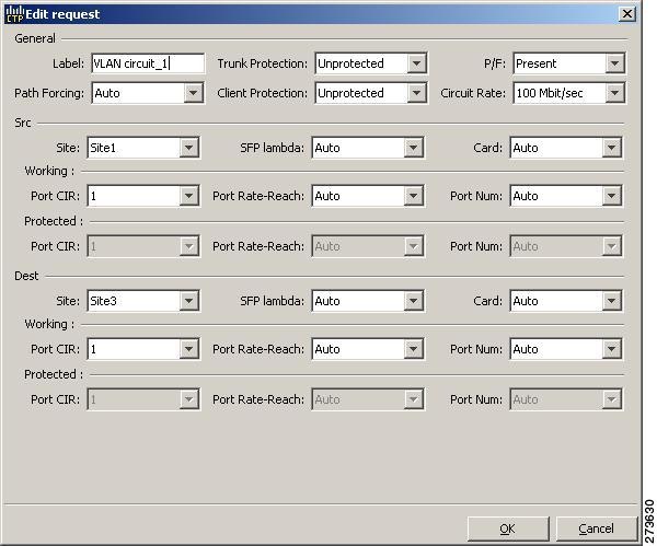
Step 6 ![]() The Edit request dialog box contains three areas of information: General, Src, and Dest.
The Edit request dialog box contains three areas of information: General, Src, and Dest.
General Area
•![]() Label—Enter the label for the circuit. By default, VLAN_Circuit_x is used.
Label—Enter the label for the circuit. By default, VLAN_Circuit_x is used.
•![]() Trunk Protection—Select the trunk protection type. Allowed values are:
Trunk Protection—Select the trunk protection type. Allowed values are:
–![]() Unprotected
Unprotected
–![]() Protected
Protected
•![]() P/F—Choose Forecast if this demand will be needed in the future. Choose Present if this demand is needed now. This parameter drives the list of pluggable port modules to be equipped on the card and affects BoM reports.
P/F—Choose Forecast if this demand will be needed in the future. Choose Present if this demand is needed now. This parameter drives the list of pluggable port modules to be equipped on the card and affects BoM reports.
•![]() Path Forcing—Allows you to force the circuit routing on the traffic subnet associated with this demand. Allowed values are:
Path Forcing—Allows you to force the circuit routing on the traffic subnet associated with this demand. Allowed values are:
–![]() Auto—(Default) Causes the tool to automatically define the trunk path.
Auto—(Default) Causes the tool to automatically define the trunk path.
–![]() Side x—Represents the label of the side on the Src site where the circuit is routed.
Side x—Represents the label of the side on the Src site where the circuit is routed.
•![]() Client Protection—Choose the client protection type. Allowed values are:
Client Protection—Choose the client protection type. Allowed values are:
–![]() Unprotected
Unprotected
–![]() Client 1+1
Client 1+1
•![]() Circuit Rate—Choose the circuit rates.
Circuit Rate—Choose the circuit rates.
Src Area
•![]() Site—Select the source site. Allowed values include the list of sites added in the WDM traffic channel.
Site—Select the source site. Allowed values include the list of sites added in the WDM traffic channel.
•![]() SFP lambda—Select the desired SFP/XFP for this port or set it to Auto to allow the tool to select an appropriate value.
SFP lambda—Select the desired SFP/XFP for this port or set it to Auto to allow the tool to select an appropriate value.
•![]() Card—Select the card. Allowed values are Auto, 10GE-XP, 10GE-EXP, GE-XP, and GE-EXP. Auto allows the tool to select an appropriate card type based on other constraints.
Card—Select the card. Allowed values are Auto, 10GE-XP, 10GE-EXP, GE-XP, and GE-EXP. Auto allows the tool to select an appropriate card type based on other constraints.
The Src area contains Working and Protected sub areas.
Working sub area
•![]() Port CIR—Select the CIR, with 1 being the highest and 0.1 being the lowest.
Port CIR—Select the CIR, with 1 being the highest and 0.1 being the lowest.
•![]() Port Rate-Reach—Select the desired PPM for this port, or set it to Auto to allow the tool to select an appropriate value.
Port Rate-Reach—Select the desired PPM for this port, or set it to Auto to allow the tool to select an appropriate value.
•![]() Port Num—Select the port number. Allowed values are Auto, 1, and 2. Auto allows the tool to select an appropriate port number based on other constraints.
Port Num—Select the port number. Allowed values are Auto, 1, and 2. Auto allows the tool to select an appropriate port number based on other constraints.
Protected sub area
These fields are enabled only if client protection is enabled in the Client Protection field.
•![]() Port CIR—Select the CIR, with 1 being the highest and 0.1 being the lowest.
Port CIR—Select the CIR, with 1 being the highest and 0.1 being the lowest.
•![]() Port Rate-Reach—Select the desired PPM for this port, or set it to Auto to allow the tool to select an appropriate value.
Port Rate-Reach—Select the desired PPM for this port, or set it to Auto to allow the tool to select an appropriate value.
•![]() Port Num—Select the port number. Allowed values are Auto, 1, and 2. Auto allows the tool to select an appropriate port number based on other constraints.
Port Num—Select the port number. Allowed values are Auto, 1, and 2. Auto allows the tool to select an appropriate port number based on other constraints.
Dest Area
•![]() Site—Select the destination site. Allowed values include the list of sites added in the WDM traffic channel.
Site—Select the destination site. Allowed values include the list of sites added in the WDM traffic channel.
•![]() SFP lambda—Select the desired SFP/XFP for this port or set it to Auto to allow the tool to select an appropriate value.
SFP lambda—Select the desired SFP/XFP for this port or set it to Auto to allow the tool to select an appropriate value.
•![]() Card—Select the card. Allowed values are Auto, 10GE-XP, 10GE-EXP, GE-XP, and GE-EXP. Auto allows the tool to select an appropriate card type based on other constraints.
Card—Select the card. Allowed values are Auto, 10GE-XP, 10GE-EXP, GE-XP, and GE-EXP. Auto allows the tool to select an appropriate card type based on other constraints.
The Dest area contains Working and Protected sub areas.
Working sub area
•![]() Port CIR—Select the CIR, with 1 being the highest and 0.1 being the lowest.
Port CIR—Select the CIR, with 1 being the highest and 0.1 being the lowest.
•![]() Port Rate-Reach—Select the desired PPM for this port, or set it to Auto to allow the tool to select an appropriate value.
Port Rate-Reach—Select the desired PPM for this port, or set it to Auto to allow the tool to select an appropriate value.
•![]() Port Num—Select the port number. Allowed values are Auto, 1 to 20. Auto allows the tool to select an appropriate port number based on other constraints.
Port Num—Select the port number. Allowed values are Auto, 1 to 20. Auto allows the tool to select an appropriate port number based on other constraints.
Protected sub area
These fields are enabled only if client protection is enabled in the Client Protection field.
•![]() Port CIR—Select the CIR, with 1 being the highest and 0.1 being the lowest.
Port CIR—Select the CIR, with 1 being the highest and 0.1 being the lowest.
•![]() Port Rate-Reach—Select the desired PPM for this port, or set it to Auto to allow the tool to select an appropriate value.
Port Rate-Reach—Select the desired PPM for this port, or set it to Auto to allow the tool to select an appropriate value.
•![]() Port Num—Select the port number. Allowed values are Auto, and 1 to 20. Auto allows the tool to select an appropriate port number based on other constraints.
Port Num—Select the port number. Allowed values are Auto, and 1 to 20. Auto allows the tool to select an appropriate port number based on other constraints.
Step 7 ![]() Click OK.
Click OK.
Step 8 ![]() Click the Check tab on the left corner of the window to generate a report showing the circuit path in the WDM traffic channel and to check any over-allocation of bandwidth (Figure 4-13). The report shows, in a row, each of the sites on the subnet, and each span in between.
Click the Check tab on the left corner of the window to generate a report showing the circuit path in the WDM traffic channel and to check any over-allocation of bandwidth (Figure 4-13). The report shows, in a row, each of the sites on the subnet, and each span in between.
Figure 4-13 Circuit Path View in an Ethernet Aggregated Demand

Step 9 ![]() To edit the demand, click the DWDM channel tab.
To edit the demand, click the DWDM channel tab.
See Figure 4-14.
The table lists the details of the demand as Demand > Service > Trail > Section.
For more information about Cisco Transport Planner icons, see Appendix A, "GUI Information and Shortcuts."
Figure 4-14 DWDM Channel View in an Ethernet Aggregated Demand

Step 10 ![]() At the service level, you can edit the following properties in the Properties pane:
At the service level, you can edit the following properties in the Properties pane:
•![]() Forecast—Changes a present section to a forecast section.
Forecast—Changes a present section to a forecast section.
•![]() Wavelength—Forces a particular channel wavelength.
Wavelength—Forces a particular channel wavelength.
–![]() Auto—Allows the tool to assign wavelength to the channel with the lowest possible cost, given the other set of constraints.
Auto—Allows the tool to assign wavelength to the channel with the lowest possible cost, given the other set of constraints.
–![]() Allowed wavelength bands—C band-32 ch.odd, L band- 32 ch.odd, C band- 40 ch., C band - 72 ch., or C band- 80 ch. Wavelengths are listed based on the selected band.
Allowed wavelength bands—C band-32 ch.odd, L band- 32 ch.odd, C band- 40 ch., C band - 72 ch., or C band- 80 ch. Wavelengths are listed based on the selected band.
Step 11 ![]() At the trail level, you can edit the following properties in the Properties pane:
At the trail level, you can edit the following properties in the Properties pane:
•![]() Wavelength—Forces a particular channel wavelength.
Wavelength—Forces a particular channel wavelength.
•![]() You can edit the following property for the source and destination sites:
You can edit the following property for the source and destination sites:
–![]() DWDM Trunk Type
DWDM Trunk Type
Step 12 ![]() At the section level, you can edit the following properties in the Properties pane:
At the section level, you can edit the following properties in the Properties pane:
•![]() Optical Bypass—Specifies the sites from the drop-down list where the channels for the current demand will be optically dropped. Sites present between the source and destination sites along the path of this section are available as options.
Optical Bypass—Specifies the sites from the drop-down list where the channels for the current demand will be optically dropped. Sites present between the source and destination sites along the path of this section are available as options.
•![]() Wavelength—Forces a particular channel wavelength.
Wavelength—Forces a particular channel wavelength.
•![]() You can edit the following property for the source and destination sites:
You can edit the following property for the source and destination sites:
–![]() DWDM Trunk Type
DWDM Trunk Type
Step 13 ![]() To add a regeneration site, click the Regeneration... icon in the toolbar of the DWDM channel tab. The Regeneration Editor appears. The regeneration site can be created only at the trail level. For more information, see the "2.7.13 Creating a Regeneration Site" section on page 2-43
To add a regeneration site, click the Regeneration... icon in the toolbar of the DWDM channel tab. The Regeneration Editor appears. The regeneration site can be created only at the trail level. For more information, see the "2.7.13 Creating a Regeneration Site" section on page 2-43
Note ![]() When siblings of the same type (service, trail, or section) are chosen, the Properties pane displays the properties that are common. The properties that are different are marked with an asterisk.
When siblings of the same type (service, trail, or section) are chosen, the Properties pane displays the properties that are common. The properties that are different are marked with an asterisk.
Step 14 ![]() Click Apply to save the changes to the channels and click Close.
Click Apply to save the changes to the channels and click Close.
4.10 Editing a TDM Aggregated Demand
Use the following procedure to edit a TDM aggregated demand:
Step 1 ![]() In the Project Explorer pane, right-click the network folder and choose Expand from the shortcut menu.
In the Project Explorer pane, right-click the network folder and choose Expand from the shortcut menu.
Step 2 ![]() In the Project Explorer pane, right-click the TDM aggregated demand and choose Edit demand from the shortcut menu. The TDM Aggregated Demand dialog box appears (Figure 2-28).
In the Project Explorer pane, right-click the TDM aggregated demand and choose Edit demand from the shortcut menu. The TDM Aggregated Demand dialog box appears (Figure 2-28).
Step 3 ![]() To make a copy of the circuit, right-click the circuit and click Copy Circuit. A new circuit appears under WDM Traffic channel with the same parameters as the original circuit.
To make a copy of the circuit, right-click the circuit and click Copy Circuit. A new circuit appears under WDM Traffic channel with the same parameters as the original circuit.
Step 4 ![]() To delete a circuit, right-click the circuit and click Delete Circuit.
To delete a circuit, right-click the circuit and click Delete Circuit.
Step 5 ![]() To modify the parameters of an existing circuit, double-click the circuit. The Edit request dialog box appears (see Figure 4-15).
To modify the parameters of an existing circuit, double-click the circuit. The Edit request dialog box appears (see Figure 4-15).
Figure 4-15 Edit Request in a TDM WDM Transport Channel

Step 6 ![]() The Edit request window contains three area of information: General, Src, and Dest.
The Edit request window contains three area of information: General, Src, and Dest.
General Area
•![]() Label—Enter the label for the circuit. By default, VLAN_Circuit_x is used.
Label—Enter the label for the circuit. By default, VLAN_Circuit_x is used.
•![]() Trunk Protection—Enter the trunk protection type. Allowed values are:
Trunk Protection—Enter the trunk protection type. Allowed values are:
–![]() Unprotected
Unprotected
–![]() UPSR
UPSR
•![]() P/F—Select Forecast if this demand will be needed in the future. Select Present if this demand is needed now. This option drives the list of pluggable port modules to be equipped on the card and affects BoM reports.
P/F—Select Forecast if this demand will be needed in the future. Select Present if this demand is needed now. This option drives the list of pluggable port modules to be equipped on the card and affects BoM reports.
•![]() Path Forcing—This option allows you to force the circuit routing on the traffic subnet associated with this demand. The following values are supported:
Path Forcing—This option allows you to force the circuit routing on the traffic subnet associated with this demand. The following values are supported:
–![]() Auto—(Default) Causes the tool to automatically define the trunk path.
Auto—(Default) Causes the tool to automatically define the trunk path.
–![]() Side x—Represents the label of the side on the Src site where the circuit is routed.
Side x—Represents the label of the side on the Src site where the circuit is routed.
•![]() Client Protection—Allowed values are:
Client Protection—Allowed values are:
–![]() Unprotected
Unprotected
–![]() 1+1 APS
1+1 APS
•![]() Circuit rate—Displays the allowed circuit rates.
Circuit rate—Displays the allowed circuit rates.
Src Area
•![]() Site—Select the source site. Allowed values include the list of sites added in the WDM traffic channel.
Site—Select the source site. Allowed values include the list of sites added in the WDM traffic channel.
•![]() SFP lambda—Select the desired SFP/XFP for this port or set it to Auto to allow the tool to select an appropriate value.
SFP lambda—Select the desired SFP/XFP for this port or set it to Auto to allow the tool to select an appropriate value.
•![]() Card—Select the card. Allowed values are Auto and ADM-x. Auto allows the tool to select an appropriate card type based on other constraints.
Card—Select the card. Allowed values are Auto and ADM-x. Auto allows the tool to select an appropriate card type based on other constraints.
The Src area contains Working and Protected sub areas.
Working sub area
•![]() Port Num—Select the port number. Allowed values are Auto and 1 to 16. Auto allows the tool to select an appropriate port number based on other constraints.
Port Num—Select the port number. Allowed values are Auto and 1 to 16. Auto allows the tool to select an appropriate port number based on other constraints.
•![]() Port Rate-Reach—Select the desired PPM for this port, or set it to Auto to allow the tool to select an appropriate value.
Port Rate-Reach—Select the desired PPM for this port, or set it to Auto to allow the tool to select an appropriate value.
Protected sub area
These fields are enabled only if client protection is enabled in the Client Protection field.
•![]() Port Num—Select the port number. Allowed values are Auto and 1 to 16. Auto allows the tool to select an appropriate port number based on other constraints.
Port Num—Select the port number. Allowed values are Auto and 1 to 16. Auto allows the tool to select an appropriate port number based on other constraints.
•![]() Port Rate-Reach—Select the desired PPM for this port, or set it to Auto to allow the tool to select an appropriate value.
Port Rate-Reach—Select the desired PPM for this port, or set it to Auto to allow the tool to select an appropriate value.
Dest Area
•![]() Site—Select the destination site. Allowed values include the list of sites added in the WDM traffic channel.
Site—Select the destination site. Allowed values include the list of sites added in the WDM traffic channel.
•![]() SFP lambda—Select the desired SFP/XFP for this port or set it to Auto to allow the tool to select an appropriate value.
SFP lambda—Select the desired SFP/XFP for this port or set it to Auto to allow the tool to select an appropriate value.
•![]() Card—Select the card. Allowed values are Auto and ADM-x. Auto allows the tool to select an appropriate card type based on other constraints.
Card—Select the card. Allowed values are Auto and ADM-x. Auto allows the tool to select an appropriate card type based on other constraints.
The Dest area contains Working and Protected sub areas.
Working sub area
•![]() Port Num—Select the port number. Allowed values are Auto and 1 to 16. Auto allows the tool to select an appropriate port number based on other constraints.
Port Num—Select the port number. Allowed values are Auto and 1 to 16. Auto allows the tool to select an appropriate port number based on other constraints.
•![]() Port Rate-Reach—Select the desired PPM for this port, or set it to Auto to allow the tool to select an appropriate value.
Port Rate-Reach—Select the desired PPM for this port, or set it to Auto to allow the tool to select an appropriate value.
Protected sub area
•![]() Port Num—Select the port number. Allowed values are Auto and 1 to 16. Auto allows the tool to select an appropriate port number based on other constraints.
Port Num—Select the port number. Allowed values are Auto and 1 to 16. Auto allows the tool to select an appropriate port number based on other constraints.
•![]() Port Rate-Reach—Select the desired PPM for this port, or set it to Auto to allow the tool to select an appropriate value.
Port Rate-Reach—Select the desired PPM for this port, or set it to Auto to allow the tool to select an appropriate value.
Step 7 ![]() Click OK.
Click OK.
Step 8 ![]() Click the Check tab in the left corner of the window to generate a report showing the circuit path in the WDM traffic channel and to check any over allocation of bandwidth (Figure 4-16). The report shows, in a row, each of the sites on the subnet, and each span in between.
Click the Check tab in the left corner of the window to generate a report showing the circuit path in the WDM traffic channel and to check any over allocation of bandwidth (Figure 4-16). The report shows, in a row, each of the sites on the subnet, and each span in between.
Figure 4-16 Circuit Path View in a TDM Aggregated Demand

Step 9 ![]() To edit the demand, click the DWDM channel tab.
To edit the demand, click the DWDM channel tab.
See Figure 4-17.
The table lists the details of the demand as Demand > Service > Trail > Section.
For more information about CTP icons, see Appendix A, "GUI Information and Shortcuts."
Figure 4-17 DWDM Channel View in a TDM Aggregated Demand

Step 10 ![]() At the service level, you can edit the following properties in the Properties pane:
At the service level, you can edit the following properties in the Properties pane:
•![]() Forecast—Changes a present section to a forecast section.
Forecast—Changes a present section to a forecast section.
•![]() Wavelength—Forces a particular channel wavelength.
Wavelength—Forces a particular channel wavelength.
–![]() Auto—Allows the tool to assign wavelength to the channel with the lowest possible cost, given the other set of constraints.
Auto—Allows the tool to assign wavelength to the channel with the lowest possible cost, given the other set of constraints.
–![]() Allowed wavelength bands—C band-32 ch.odd, L band- 32 ch.odd, C band- 40 ch., C band - 72 ch., or C band- 80 ch. Wavelengths are listed based on the selected band.
Allowed wavelength bands—C band-32 ch.odd, L band- 32 ch.odd, C band- 40 ch., C band - 72 ch., or C band- 80 ch. Wavelengths are listed based on the selected band.
Step 11 ![]() At the trail level, you can edit the following properties in the Properties pane:
At the trail level, you can edit the following properties in the Properties pane:
•![]() Wavelength—Forces a particular channel wavelength.
Wavelength—Forces a particular channel wavelength.
•![]() You can edit the following property for the source and destination sites:
You can edit the following property for the source and destination sites:
–![]() DWDM Trunk Type
DWDM Trunk Type
Step 12 ![]() At the section level, you can edit the following properties in the Properties pane:
At the section level, you can edit the following properties in the Properties pane:
•![]() Optical Bypass—Specifies the sites from the drop-down list where the channels for the current demand will be optically dropped. Sites present between the source and destination sites along the path of this section are available as options.
Optical Bypass—Specifies the sites from the drop-down list where the channels for the current demand will be optically dropped. Sites present between the source and destination sites along the path of this section are available as options.
•![]() Wavelength—Forces a particular channel wavelength.
Wavelength—Forces a particular channel wavelength.
•![]() You can edit the following property for the source and destination sites:
You can edit the following property for the source and destination sites:
–![]() DWDM Trunk Type
DWDM Trunk Type
Step 13 ![]() To add a regeneration site, click the Regeneration... icon in the toolbar of the DWDM channel tab. The Regeneration Editor appears. The regeneration site can be created only at the trail level. For more information, see the "2.7.13 Creating a Regeneration Site" section on page 2-43.
To add a regeneration site, click the Regeneration... icon in the toolbar of the DWDM channel tab. The Regeneration Editor appears. The regeneration site can be created only at the trail level. For more information, see the "2.7.13 Creating a Regeneration Site" section on page 2-43.
Note ![]() When siblings of the same type (service, trail, or section) are chosen, the Properties pane displays the properties that are common. The properties that are different are marked with an asterisk.
When siblings of the same type (service, trail, or section) are chosen, the Properties pane displays the properties that are common. The properties that are different are marked with an asterisk.
Step 14 ![]() Click Apply to save the changes to the channels and click Close.
Click Apply to save the changes to the channels and click Close.
4.11 Editing Fiber Span, Pair, and Fiber Parameters
Using the Properties pane, you can manage a fiber span, a fiber pair, and individual fibers. A fiber pair consists of two different fibers (clockwise and counter-clockwise). Table 4-2 lists the properties that you can modify for a fiber span, pair, or fiber.
Use the following procedure to edit fiber span, pair, and fiber parameters:
Step 1 ![]() In the Project Explorer, right-click the Fibers folder and choose Expand from the shortcut menu.
In the Project Explorer, right-click the Fibers folder and choose Expand from the shortcut menu.
Step 2 ![]() In the Project Explorer tree, click one of the following. The options available for editing in the Properties pane change depending on your selection.
In the Project Explorer tree, click one of the following. The options available for editing in the Properties pane change depending on your selection.
•![]() To edit a fiber span, click the duct identifier.
To edit a fiber span, click the duct identifier.
•![]() To edit a fiber pair, click the fiber pair identifier.
To edit a fiber pair, click the fiber pair identifier.
•![]() To edit an individual fiber, click the fiber identifier.
To edit an individual fiber, click the fiber identifier.
Step 3 ![]() In the Properties pane, edit the following parameters, as necessary. See Table 4-2 for the properties that you can change for a fiber span, fiber pair, or individual fiber.
In the Properties pane, edit the following parameters, as necessary. See Table 4-2 for the properties that you can change for a fiber span, fiber pair, or individual fiber.
•![]() Name—Type the desired name for the fiber span, pair, or fiber.
Name—Type the desired name for the fiber span, pair, or fiber.
•![]() Ageing loss—Type the EOL aging loss value. The EOL loss per span value is added at the end of life to each discrete fiber in the network (for example, to add an EOL margin for splicing). If you set the ageing factor, you do not need to set the ageing loss.
Ageing loss—Type the EOL aging loss value. The EOL loss per span value is added at the end of life to each discrete fiber in the network (for example, to add an EOL margin for splicing). If you set the ageing factor, you do not need to set the ageing loss.
•![]() Ageing factor—Type the number to factor fiber aging. This factor is multiplied by the SOL total span loss without connectors. If you set the ageing loss, you do not need to set the ageing factor.
Ageing factor—Type the number to factor fiber aging. This factor is multiplied by the SOL total span loss without connectors. If you set the ageing loss, you do not need to set the ageing factor.
•![]() Type—Choose the type of fiber for each span in the network.
Type—Choose the type of fiber for each span in the network.
•![]() Length—Type the span length. The displayed unit of measure is retrieved from the Span Measurements Units field.
Length—Type the span length. The displayed unit of measure is retrieved from the Span Measurements Units field.
•![]() Length Based Loss—Check to define if the fiber loss is specified as an absolute value or leave unchecked if fiber loss is derived from the span length.
Length Based Loss—Check to define if the fiber loss is specified as an absolute value or leave unchecked if fiber loss is derived from the span length.
•![]() Connector loss [Site 1]—Type the concentrated connector loss at the end of the span.
Connector loss [Site 1]—Type the concentrated connector loss at the end of the span.
•![]() Connector loss [Site 2]—Type the concentrated connector loss at the end of the span.
Connector loss [Site 2]—Type the concentrated connector loss at the end of the span.
•![]() Abs loss w/o conn [dB]—Type the start of life link fiber loss for each span, without the connector concentrated loss. The total SOL loss without connectors is equal to the loss factor multiplied by the length. In the Length Based model, this value is calculated automatically.
Abs loss w/o conn [dB]—Type the start of life link fiber loss for each span, without the connector concentrated loss. The total SOL loss without connectors is equal to the loss factor multiplied by the length. In the Length Based model, this value is calculated automatically.
•![]() CD—Type the fiber CD factor. The default value is dependent on the selected fiber type. Any value that you enter is lost whenever you change the fiber type. Chromatic dispersion is always entered in ps/nm/km. Fiber chromatic dispersion is defined for the middle of the wavelength band. C band is defined at 1545.3 nm; L band is defined at 1590.4 nm.
CD—Type the fiber CD factor. The default value is dependent on the selected fiber type. Any value that you enter is lost whenever you change the fiber type. Chromatic dispersion is always entered in ps/nm/km. Fiber chromatic dispersion is defined for the middle of the wavelength band. C band is defined at 1545.3 nm; L band is defined at 1590.4 nm.
•![]() PMD—Type the PMD factor. The default value is dependent on the selected fiber type. Any value that you enter is lost whenever you change the fiber type. PMD is always entered in ps/nm/km.
PMD—Type the PMD factor. The default value is dependent on the selected fiber type. Any value that you enter is lost whenever you change the fiber type. PMD is always entered in ps/nm/km.
•![]() Loss—Type the value of the SOL fiber loss per kilometer used to calculate the loss of each span in the network. The fiber loss factor is always entered in dB/km.
Loss—Type the value of the SOL fiber loss per kilometer used to calculate the loss of each span in the network. The fiber loss factor is always entered in dB/km.
•![]() Raman Amplified—Check this option to enable Raman amplification. It allows placement of Raman amplifiers on both end-points of the span. When this option is checked, the Raman amplification properties of the C-band amplifier are enabled.
Raman Amplified—Check this option to enable Raman amplification. It allows placement of Raman amplifiers on both end-points of the span. When this option is checked, the Raman amplification properties of the C-band amplifier are enabled.
Note ![]() You can choose adjacent spans as Raman amplified and choose a site between these spans as a pass-through site. The algorithm treats the adjacent spans as one span and places the Raman amplifier on the external sites on the ends of the span. The Raman amplified span is indicated by two red dots.
You can choose adjacent spans as Raman amplified and choose a site between these spans as a pass-through site. The algorithm treats the adjacent spans as one span and places the Raman amplifier on the external sites on the ends of the span. The Raman amplified span is indicated by two red dots.
•![]() Attenuation at Lambda One—Enter the attenuation value for the first Raman signal. The default value is Auto, which allows the tool to select an appropriate value.
Attenuation at Lambda One—Enter the attenuation value for the first Raman signal. The default value is Auto, which allows the tool to select an appropriate value.
•![]() Attenuation at Lambda Two—Enter the attenuation value for the second Raman signal. The default value is Auto, which allows the tool to select an appropriate value.
Attenuation at Lambda Two—Enter the attenuation value for the second Raman signal. The default value is Auto, which allows the tool to select an appropriate value.
Step 4 ![]() As needed, view the following totals for a fiber span, fiber pair, or individual fiber on the Properties pane:
As needed, view the following totals for a fiber span, fiber pair, or individual fiber on the Properties pane:
•![]() Loss BOL—(Display only) Displays the total loss beginning of life (BOL) calculation.
Loss BOL—(Display only) Displays the total loss beginning of life (BOL) calculation.
Note ![]() BOL is also referred to as SOL.
BOL is also referred to as SOL.
•![]() Loss EOL—(Display only) Displays the total loss EOL calculation.
Loss EOL—(Display only) Displays the total loss EOL calculation.
•![]() CD—(Display only) Displays the total chromatic dispersion.
CD—(Display only) Displays the total chromatic dispersion.
•![]() PMD—(Display only) Displays the total polarization mode dispersion.
PMD—(Display only) Displays the total polarization mode dispersion.
4.12 Editing Fiber Spans, Pairs, and Fibers Using the Fibres Dialog Box
The Fibres Dialog lists all fiber spans, pairs, and fibers in the network. Use the following procedure to view and edit fiber parameters from the Fibres Dialog box.
Step 1 ![]() In the Project Explorer tree, right-click the Fibres folder in the desired network and choose Fibres Dialog from the shortcut menu. The Fibres Dialog appears (Figure 4-18).
In the Project Explorer tree, right-click the Fibres folder in the desired network and choose Fibres Dialog from the shortcut menu. The Fibres Dialog appears (Figure 4-18).
Figure 4-18 Fibres Dialog

Table 4-3 describes the columns on the Fibres Dialog.
Step 2 ![]() To edit a fiber span, pair, or fiber, click the desired item in the Fibres Dialog. The Properties pane in the right area of the Fibres Dialog displays the properties for the selected item.
To edit a fiber span, pair, or fiber, click the desired item in the Fibres Dialog. The Properties pane in the right area of the Fibres Dialog displays the properties for the selected item.
Step 3 ![]() In the Properties pane, edit the following parameters, as necessary. See Table 4-2 for the properties that you can change for a fiber span, fiber pair, or individual fiber.
In the Properties pane, edit the following parameters, as necessary. See Table 4-2 for the properties that you can change for a fiber span, fiber pair, or individual fiber.
•![]() Name—Type the desired name for the fiber span, pair, or fiber.
Name—Type the desired name for the fiber span, pair, or fiber.
•![]() Ageing loss—Type the EOL aging loss value. The EOL loss per span value is added at the end of life to each discrete fiber in the network (for example, to add an EOL margin for splicing). If you set the ageing factor, you do not need to set the ageing loss.
Ageing loss—Type the EOL aging loss value. The EOL loss per span value is added at the end of life to each discrete fiber in the network (for example, to add an EOL margin for splicing). If you set the ageing factor, you do not need to set the ageing loss.
•![]() Ageing factor—Type the number to factor fiber aging. This factor is multiplied by the SOL total span loss without connectors. If you set the ageing loss, you do not need to set the ageing factor.
Ageing factor—Type the number to factor fiber aging. This factor is multiplied by the SOL total span loss without connectors. If you set the ageing loss, you do not need to set the ageing factor.
•![]() Type—Choose the type of fiber for each span in the network.
Type—Choose the type of fiber for each span in the network.
•![]() Length—Type the span length. The displayed unit of measure is retrieved from the Span Measurements Units field.
Length—Type the span length. The displayed unit of measure is retrieved from the Span Measurements Units field.
•![]() Length Based Loss—Check to define if the fiber loss is specified as an absolute value or leave unchecked if fiber loss is derived from the span length.
Length Based Loss—Check to define if the fiber loss is specified as an absolute value or leave unchecked if fiber loss is derived from the span length.
•![]() Connector loss [Site 1]—Type the concentrated connector loss at the end of the span.
Connector loss [Site 1]—Type the concentrated connector loss at the end of the span.
•![]() Connector loss [Site 2]—Type the concentrated connector loss at the end of the span.
Connector loss [Site 2]—Type the concentrated connector loss at the end of the span.
•![]() Abs loss w/o conn [dB]—Type the start of life link fiber loss for each span, without the connector concentrated loss. The total SOL loss without connectors is equal to the loss factor multiplied by the length. In the Length Based model, this value is calculated automatically.
Abs loss w/o conn [dB]—Type the start of life link fiber loss for each span, without the connector concentrated loss. The total SOL loss without connectors is equal to the loss factor multiplied by the length. In the Length Based model, this value is calculated automatically.
•![]() CD—Type the fiber CD factor. The default value is dependent on the selected fiber type. Any value that you enter is lost whenever you change the fiber type. Chromatic dispersion is always entered in ps/nm/km. Fiber chromatic dispersion is defined for the middle of the wavelength band. C band is defined at 1545.3 nm; L band is defined at 1590.4 nm.
CD—Type the fiber CD factor. The default value is dependent on the selected fiber type. Any value that you enter is lost whenever you change the fiber type. Chromatic dispersion is always entered in ps/nm/km. Fiber chromatic dispersion is defined for the middle of the wavelength band. C band is defined at 1545.3 nm; L band is defined at 1590.4 nm.
•![]() PMD—Type the PMD factor. The default value is dependent on the selected fiber type. Any value that you enter is lost whenever you change the fiber type. PMD is always entered in ps/nm/km.
PMD—Type the PMD factor. The default value is dependent on the selected fiber type. Any value that you enter is lost whenever you change the fiber type. PMD is always entered in ps/nm/km.
•![]() Loss—Type the value of the SOL fiber loss per kilometer used to calculate the loss of each span in the network. The fiber loss factor is always entered in dB/km.
Loss—Type the value of the SOL fiber loss per kilometer used to calculate the loss of each span in the network. The fiber loss factor is always entered in dB/km.
•![]() Raman Amplified—Check this option to enable Raman amplification. It allows placement of Raman amplifiers on both end-points of the span. When this option is checked, the Raman amplification properties of the C-band amplifier are enabled.
Raman Amplified—Check this option to enable Raman amplification. It allows placement of Raman amplifiers on both end-points of the span. When this option is checked, the Raman amplification properties of the C-band amplifier are enabled.
Note ![]() You can select adjacent spans as Raman Amplified and select a site between these spans as a pass through site. The algorithm treats the adjacent spans as one span and places the Raman amplifier on the external sites on the ends of the span.
You can select adjacent spans as Raman Amplified and select a site between these spans as a pass through site. The algorithm treats the adjacent spans as one span and places the Raman amplifier on the external sites on the ends of the span.
•![]() Attenuation at Lambda One—Enter the attenuation value for the first Raman signal. The default value is Auto, which allows the tool to select an appropriate value.
Attenuation at Lambda One—Enter the attenuation value for the first Raman signal. The default value is Auto, which allows the tool to select an appropriate value.
•![]() Attenuation at Lambda Two—Enter the attenuation value for the second Raman signal. The default value is Auto, which allows the tool to select an appropriate value.
Attenuation at Lambda Two—Enter the attenuation value for the second Raman signal. The default value is Auto, which allows the tool to select an appropriate value.
Cisco Transport Planner updates the Fibres Dialog box with the new value.
Step 4 ![]() As needed, view the following totals for a fiber span, fiber pair, or individual fiber on the Properties pane:
As needed, view the following totals for a fiber span, fiber pair, or individual fiber on the Properties pane:
•![]() Loss BOL—(Display only) Displays the total loss BOL calculation.
Loss BOL—(Display only) Displays the total loss BOL calculation.
Note ![]() BOL is also referred to as SOL.
BOL is also referred to as SOL.
•![]() Loss EOL—(Display only) Displays the total loss EOL calculation.
Loss EOL—(Display only) Displays the total loss EOL calculation.
•![]() CD—(Display only) Displays the total chromatic dispersion.
CD—(Display only) Displays the total chromatic dispersion.
•![]() PMD—(Display only) Displays the total polarization mode dispersion.
PMD—(Display only) Displays the total polarization mode dispersion.
Step 5 ![]() Click OK.
Click OK.
4.12.1 Exporting the Fiber Spans, Pairs, and Fibers in a Network
Use the following procedure to export all spans, pairs, and single fibers in a network in XLS format:
Step 1 ![]() In the Project Explorer tree, right-click the Fibres folder in the desired network and choose Fibres Dialog from the shortcut menu. The Fibres Dialog appears (Figure 4-18).
In the Project Explorer tree, right-click the Fibres folder in the desired network and choose Fibres Dialog from the shortcut menu. The Fibres Dialog appears (Figure 4-18).
Step 2 ![]() Click Export. The Fibres Export dialog box appears.
Click Export. The Fibres Export dialog box appears.
Step 3 ![]() Navigate to the desired directory, type the XLS filename, and click Save.
Navigate to the desired directory, type the XLS filename, and click Save.
4.13 Rack Rules
This section describes the following rules:
•![]() Fiber Storage Placement Rules
Fiber Storage Placement Rules
4.13.1 General Placement Rules
The following general rules apply to rack filling:
•![]() CTP fills the shelves in the rack from the top in the following order:
CTP fills the shelves in the rack from the top in the following order:
1. ![]() PDP
PDP
2. ![]() Ethernet switch shelf
Ethernet switch shelf
3. ![]() EAP shelf (fan out)
EAP shelf (fan out)
4. ![]() Y-cable shelves (Flex Layer or Y-cable FMT)
Y-cable shelves (Flex Layer or Y-cable FMT)
5. ![]() Band Combiner/Interleaver-De-Interleaver Flex Layer shelf
Band Combiner/Interleaver-De-Interleaver Flex Layer shelf
6. ![]() DCU shelves
DCU shelves
7. ![]() Patch-panel L shelves (PP-64-LC and FMT-32-Ch)
Patch-panel L shelves (PP-64-LC and FMT-32-Ch)
8. ![]() MSTP optical shelves
MSTP optical shelves
9. ![]() PATCH-PANEL shelves (for ETSI)
PATCH-PANEL shelves (for ETSI)
10. ![]() Fiber storage shelf
Fiber storage shelf
11. ![]() PP-mesh
PP-mesh
12. ![]() Transponder shelves (Present)
Transponder shelves (Present)
13. ![]() Line card shelves (Present)
Line card shelves (Present)
14. ![]() Transponder shelves (Forecast)
Transponder shelves (Forecast)
15. ![]() Line card shelves (Forecast)
Line card shelves (Forecast)
•![]() The shelves from the DCU to the fiber storage unit are related to the optical shelf and must be used for every optical shelf.
The shelves from the DCU to the fiber storage unit are related to the optical shelf and must be used for every optical shelf.
•![]() The Power Distribution Panel (PDP) is always at the top of each rack and it is assumed to be a part of the rack.
The Power Distribution Panel (PDP) is always at the top of each rack and it is assumed to be a part of the rack.
•![]() CTP places the MSTP optical shelf in the first available (layout unlocked) shelf position, starting from the first rack of the site or from the first rack of each side (for sites with site protection).
CTP places the MSTP optical shelf in the first available (layout unlocked) shelf position, starting from the first rack of the site or from the first rack of each side (for sites with site protection).
•![]() CTP places as many shelves as possible within a rack, taking into account the height of the racks and the height of each shelf as shown in the following table:
CTP places as many shelves as possible within a rack, taking into account the height of the racks and the height of each shelf as shown in the following table:
4.13.2 DCU Placement Rules
The following rules apply to DCU placement:
•![]() CTP places the DCU shelves and DCU units on top of each MSTP optical shelf connected to the entering fiber of the span (or spans) to be compensated.
CTP places the DCU shelves and DCU units on top of each MSTP optical shelf connected to the entering fiber of the span (or spans) to be compensated.
•![]() If no room is available within the recommended space (for example, during an upgrade), then CTP places the DCU shelves and units in any of the other racks, starting preferably in the same rack as the MSTP optical shelf.
If no room is available within the recommended space (for example, during an upgrade), then CTP places the DCU shelves and units in any of the other racks, starting preferably in the same rack as the MSTP optical shelf.
•![]() CTP computes the DCU patch-cord length with respect to the preamplifier position, using the same rules as the ones defined for TXP/MXP units.
CTP computes the DCU patch-cord length with respect to the preamplifier position, using the same rules as the ones defined for TXP/MXP units.
4.13.3 Fiber Storage Placement Rules
The following rules apply to fibre storage placement:
•![]() If the fiber storage option is flagged as ON/AUTO, CTP places one fiber storage shelf below each MSTP optical shelf.
If the fiber storage option is flagged as ON/AUTO, CTP places one fiber storage shelf below each MSTP optical shelf.
•![]() If MSTP optical shelves are in different racks, CTP places a fiber storage shelf in each rack with an MSTP optical shelf.
If MSTP optical shelves are in different racks, CTP places a fiber storage shelf in each rack with an MSTP optical shelf.
4.13.4 Air Ramp Placement Rules
The following rules apply to air ramp placement:
•![]() An ANSI shelf must always have another ANSI shelf, an air ramp, or an empty space at the bottom of it.
An ANSI shelf must always have another ANSI shelf, an air ramp, or an empty space at the bottom of it.
•![]() An ETSI shelf must always have one air ramp on top of it and one air ramp or an empty space at the bottom of it.
An ETSI shelf must always have one air ramp on top of it and one air ramp or an empty space at the bottom of it.
•![]() Air ramp is not required on top of the ETSI shelf if the ETSI shelf is placed directly below the PDP in the rack.
Air ramp is not required on top of the ETSI shelf if the ETSI shelf is placed directly below the PDP in the rack.
CTP automatically adjusts the air ramp placement when changes occur in the layout options.
4.13.5 Patch Panel Placement Rules
The following rules apply to patch panel placement:
•![]() If you choose 15454-PP-64-LC, 15454-PP2-64-LC, or 15454-80-LC-PP-II patch-panel, CTP deploys one patch panel for each side in the site.
If you choose 15454-PP-64-LC, 15454-PP2-64-LC, or 15454-80-LC-PP-II patch-panel, CTP deploys one patch panel for each side in the site.
For example:
–![]() For a C-band /Odd channel terminal equipped with 32-Mux/Demux units: one path panel shelf
For a C-band /Odd channel terminal equipped with 32-Mux/Demux units: one path panel shelf
–![]() For a C-band /Odd channel full-OADM: two patch-panel shelves.
For a C-band /Odd channel full-OADM: two patch-panel shelves.
CTP places the two patch-panel shelves together in the same rack when site protection is disabled and places them in two separate rack when site protection is enabled.
•![]() CTP places the patch-panel shelves together on top of the OTS main shelf (under the DCU).
CTP places the patch-panel shelves together on top of the OTS main shelf (under the DCU).
•![]() If the length of the MPO does not allow the patch-panels to be together on top of the OTS main shelf (under the DCU shelves), then CTP places the patch-panel shelves according to the following rules:
If the length of the MPO does not allow the patch-panels to be together on top of the OTS main shelf (under the DCU shelves), then CTP places the patch-panel shelves according to the following rules:
–![]() ETSI (without node protection)
ETSI (without node protection)
If the OTS units in both sides can be hosted within one shelf, then the layout is as shown in Figure 4-19.
Figure 4-19 Patch-Panel Placement for ETSI Without Node Protection
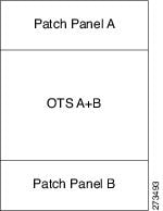
–![]() ANSI and ETSI (without node protection)
ANSI and ETSI (without node protection)
If the OTS units in both sides cannot be hosted within one shelf, then the layout is as shown in Figure 4-20.
Figure 4-20 Patch-Panel Placement for ANSI and ETSI Without Node Protection

–![]() ANSI and ETSI 3-N degree
ANSI and ETSI 3-N degree
For ANSI and ETSI 3-N degree, the layout is as shown in Figure 4-21.
Figure 4-21 Patch-Panel Placement for ANSI and ETSI 3-N Degree

–![]() Side occupying more than one shelf—ANSI
Side occupying more than one shelf—ANSI
For a side occupying more than one shelf (ANSI), the layout is as shown in Figure 4-22.
Figure 4-22 Patch-Panel Placement—Side Occupying More than One Shelf (ANSI)

–![]() Side occupying more than one shelf—ETSI
Side occupying more than one shelf—ETSI
For a side occupying more than one shelf (ETSI), the layout is as shown in Figure 4-23.
Figure 4-23 Patch-Panel Placement—Side Occupying More than One Shelf (ETSI)

•![]() If the OTS optical units cannot fit in one MSTP optical shelf, then CTP hosts the cards that are connected to the patch panel through MPO cables in the same shelf and places the patch-panel shelf on top of it.
If the OTS optical units cannot fit in one MSTP optical shelf, then CTP hosts the cards that are connected to the patch panel through MPO cables in the same shelf and places the patch-panel shelf on top of it.
4.13.6 Client Shelf Placement Rules
The following rules apply to client shelf placement:
•![]() Node protection as same shelf:
Node protection as same shelf:
CTP places the client shelves from the first rack in an optimized manner.
•![]() Node protection as separated shelves:
Node protection as separated shelves:
CTP places the client shelves, with unprotected or 1+1 protected cards, with their respective OTS racks. See Figure 4-24.
Figure 4-24 Client Shelf Placement-Node protection as Separated Shelves

•![]() CTP places the client shelves, filled with protection and aggregated demands, from the first rack in an optimized manner. CTP places these shelves after placing the unprotected or 1+1 protected shelves. CTP places the remaining client shelves, after filling the last OTS side rack, in new racks placed after the last OTS side rack. See Figure 4-25.
CTP places the client shelves, filled with protection and aggregated demands, from the first rack in an optimized manner. CTP places these shelves after placing the unprotected or 1+1 protected shelves. CTP places the remaining client shelves, after filling the last OTS side rack, in new racks placed after the last OTS side rack. See Figure 4-25.
Figure 4-25 Client Shelf Placement-Protection and Aggregated Demand

4.13.7 Y-Cable Placement Rules
The following rules apply to Y-cable placement:
•![]() CTP numbers each Y-cable protection module within the Y-cable protection shelf with progressive numbers (1 to n).
CTP numbers each Y-cable protection module within the Y-cable protection shelf with progressive numbers (1 to n).
•![]() The required number of Y-cable protection modules depends on the number of client ports (on transponders and muxponders) implementing the Y-cable protection within the racks in the site.
The required number of Y-cable protection modules depends on the number of client ports (on transponders and muxponders) implementing the Y-cable protection within the racks in the site.
•![]() Each Y-cable protection module can only connect transponders within the same rack.
Each Y-cable protection module can only connect transponders within the same rack.
•![]() The shelf containing the Y-cable protection modules can be partially full.
The shelf containing the Y-cable protection modules can be partially full.
•![]() CTP uses single-mode or multimode Y-cable protection modules depending on the client interface on the transponder implementing the Y-cable protection.
CTP uses single-mode or multimode Y-cable protection modules depending on the client interface on the transponder implementing the Y-cable protection.
•![]() If a rack cannot physically hold all the Y-cable protection modules required to manage the Y-cable protected transponders, then CTP moves one client shelf (for example, the bottom shelf) to the next rack. If the moved shelf contains Y-cable protected transponders, then CTP moves the related Y-cable protection modules together.
If a rack cannot physically hold all the Y-cable protection modules required to manage the Y-cable protected transponders, then CTP moves one client shelf (for example, the bottom shelf) to the next rack. If the moved shelf contains Y-cable protected transponders, then CTP moves the related Y-cable protection modules together.
•![]() CTP shifts the shelf if (as mentioned in the previous item) no space is available within the rack to hold the shelves and the Y-cable protection modules required to support both present and future traffic demands.
CTP shifts the shelf if (as mentioned in the previous item) no space is available within the rack to hold the shelves and the Y-cable protection modules required to support both present and future traffic demands.
•![]() A Y-cable protection FlexLayer module (supporting two different Y-cable protection groups) in a rack could be partially unused even if additional shelves equipped with transponders are deployed in a rack that follows in the site.
A Y-cable protection FlexLayer module (supporting two different Y-cable protection groups) in a rack could be partially unused even if additional shelves equipped with transponders are deployed in a rack that follows in the site.
4.14 Shelf Rules
This section includes the following rules:
•![]() General Shelf Placement Rules
General Shelf Placement Rules
•![]() FlexLayer OADM Unit Placement Rules
FlexLayer OADM Unit Placement Rules
•![]() Hybrid Site Layout Constraints
Hybrid Site Layout Constraints
4.14.1 General Shelf Placement Rules
The following subsections list the general rules for and constraints on card slot placement.
4.14.1.1 Card Slots
Each unit represented in the layout includes the slot occupancy provided in the following lists for one-slot and two-slot units.
•![]() One-slot units:
One-slot units:
–![]() Blank
Blank
–![]() AIC
AIC
–![]() TCC2P
TCC2P
–![]() OSCM, OSC-CSM
OSCM, OSC-CSM
–![]() AD-1C, AD-2C, AD-4C
AD-1C, AD-2C, AD-4C
–![]() AD-1B, AD-4B
AD-1B, AD-4B
–![]() 4MD
4MD
–![]() OPT-PRE, OPT-BST, OPT-BST-L, OPT-BST-E
OPT-PRE, OPT-BST, OPT-BST-L, OPT-BST-E
–![]() AMP-17-C
AMP-17-C
–![]() AMP-C
AMP-C
–![]() 32-DMX
32-DMX
–![]() 40-DMX-C
40-DMX-C
–![]() 40-DMX-E
40-DMX-E
–![]() 40-MUX-C
40-MUX-C
–![]() MMU
MMU
–![]() PSM
PSM
–![]() All the line cards
All the line cards
–![]() All TXP and MXP units
All TXP and MXP units
–![]() 10GE-XP
10GE-XP
–![]() OTU2-XP
OTU2-XP
–![]() MS-ISC-100T
MS-ISC-100T
•![]() Two-slot units:
Two-slot units:
–![]() 32MUX-O
32MUX-O
–![]() 32DMX-O
32DMX-O
–![]() 32-WSS
32-WSS
–![]() 40-WXC
40-WXC
–![]() 40-WSS-C
40-WSS-C
–![]() 40-WSS-E
40-WSS-E
–![]() OPT-AMP-L
OPT-AMP-L
–![]() OPT-RAMP-C
OPT-RAMP-C
–![]() ADM-10G, GE-XP
ADM-10G, GE-XP
•![]() FlexLayer module
FlexLayer module
–![]() C/L Band Combiner
C/L Band Combiner
–![]() 50/100-Ghz Interleaver/De-Interleaver
50/100-Ghz Interleaver/De-Interleaver
•![]() Y-cable FlexLayer module
Y-cable FlexLayer module
–![]() 15216 FLB-2, FLA-8, CS-4
15216 FLB-2, FLA-8, CS-4
•![]() DCU module
DCU module
–![]() A DCU module takes half of the DCU shelf space.
A DCU module takes half of the DCU shelf space.
4.14.1.2 Card Slot Constraints
•![]() CTP places TCC units in slots 7 or 11. The Generated layout always places both working and standby TCC unit on each shelf.
CTP places TCC units in slots 7 or 11. The Generated layout always places both working and standby TCC unit on each shelf.
•![]() CTP places AIC units in slot 9.
CTP places AIC units in slot 9.
•![]() CTP places OSCM units only in slots 8 or 10.
CTP places OSCM units only in slots 8 or 10.
•![]() CTP places MS-ISC-100T units in slots 6 and 12
CTP places MS-ISC-100T units in slots 6 and 12
•![]() CTP places 2.5G and 10G line cards only in slots 5, 6, 12, and 13.
CTP places 2.5G and 10G line cards only in slots 5, 6, 12, and 13.
•![]() For OSMINE compliance, the CTP does not place any card (if there is no booster placed by algorithm for that side) in slot 2 or in slot 16. CTP places a blank faceplate in slot 2 and 16. If the OTS side contains booster card, it is placed in slot 2 or slot 16.
For OSMINE compliance, the CTP does not place any card (if there is no booster placed by algorithm for that side) in slot 2 or in slot 16. CTP places a blank faceplate in slot 2 and 16. If the OTS side contains booster card, it is placed in slot 2 or slot 16.
4.14.2 Multishelf Placement Rules
•![]() Multishelf site aggregate some of shelves that do not hold XC units.
Multishelf site aggregate some of shelves that do not hold XC units.
•![]() CTP creates the layout even if the MSTP equipment (for example, OTS and TXP/MXP units, but not ITU line cards) in a site is to be deployed on more than the available number of MSTP shelves. In this case CTP generates the error message, "Generated layout exceeded the maximum number of shelves in a multishelf site".
CTP creates the layout even if the MSTP equipment (for example, OTS and TXP/MXP units, but not ITU line cards) in a site is to be deployed on more than the available number of MSTP shelves. In this case CTP generates the error message, "Generated layout exceeded the maximum number of shelves in a multishelf site".
•![]() The MSTP and MSPP (line card) shelves can be placed on the same rack even if MSPP shelves cannot be part of the multishelf management.
The MSTP and MSPP (line card) shelves can be placed on the same rack even if MSPP shelves cannot be part of the multishelf management.
•![]() By default, CTP designates the OTS optical shelf in rack number 1 as the Node Controller (NC).
By default, CTP designates the OTS optical shelf in rack number 1 as the Node Controller (NC).
•![]() The software running on the node assigns a shelf number when a subtended shelf is registered to the NC. You can assign any of the available numbers in the allowed range [1 to 8]. The numbers do not have to be consecutive.
The software running on the node assigns a shelf number when a subtended shelf is registered to the NC. You can assign any of the available numbers in the allowed range [1 to 8]. The numbers do not have to be consecutive.
•![]() The maximum number of shelves in a multishelf configuration are:
The maximum number of shelves in a multishelf configuration are:
–![]() 8 when using a multishelf integrated switch
8 when using a multishelf integrated switch
–![]() 12 when using a multishelf external switch
12 when using a multishelf external switch
4.14.2.1 Multishelf Integrated Switches
The following subsections list the placement rules for different types of multishelf configurations.
•![]() The LAN architecture of different MSTP shelves is implemented using 15454 MS-ISC-100T cards.
The LAN architecture of different MSTP shelves is implemented using 15454 MS-ISC-100T cards.
•![]() To cope with TCC redundancy and to guarantee multishelf LAN reliability, 15454 MS-ISC-100T cards are redundant (connected to both the active and standby TCC units).
To cope with TCC redundancy and to guarantee multishelf LAN reliability, 15454 MS-ISC-100T cards are redundant (connected to both the active and standby TCC units).
•![]() CTP places both 15454 MS-ISC-100T cards in Node Controller (NC) shelf.
CTP places both 15454 MS-ISC-100T cards in Node Controller (NC) shelf.
•![]() CTP places 15454 MS-ISC-100T cards in slots 6 and 12.
CTP places 15454 MS-ISC-100T cards in slots 6 and 12.
4.14.2.2 Multishelf External Switch
•![]() The LAN architecture of different MSTP shelves is implemented using Catalyst 2950G-24-EI-DC units.
The LAN architecture of different MSTP shelves is implemented using Catalyst 2950G-24-EI-DC units.
•![]() To cope with TCC redundancy and to guarantee multishelf LAN reliability, Catalyst 2950G-24-EI-DC units are redundant (connected to both the active and standby TCC units).
To cope with TCC redundancy and to guarantee multishelf LAN reliability, Catalyst 2950G-24-EI-DC units are redundant (connected to both the active and standby TCC units).
•![]() CTP places both Catalyst 2950G-24-EI-DC units on the same rack of the Node Controller (NC) shelf.
CTP places both Catalyst 2950G-24-EI-DC units on the same rack of the Node Controller (NC) shelf.
4.14.2.3 Multishelf Separate Shelves
CTP orders the racks by first placing all the units facing one side and then all the other units facing the other side.
4.14.2.4 Multishelf Separate Nodes
•![]() If the site functionality is not ROADM or OADM, CTP displays the following warning message at the end of the network analysis:
If the site functionality is not ROADM or OADM, CTP displays the following warning message at the end of the network analysis:
"Separate nodes are allowed on ROADM/OADM sites only and cannot be applied to Site 'x'"
•![]() If the site functionality is ROADM or OADM, CTP orders the rack by first placing all the units facing one side and then all the other units facing the other side.
If the site functionality is ROADM or OADM, CTP orders the rack by first placing all the units facing one side and then all the other units facing the other side.
•![]() From Release 9.0, for OIC nodes with multishelf configuration, all the sides are placed in the layout in an optimized manner (like OXC). The entire site is considered as one Network Element. Two MSISC cards or two CAT switches are used in this configuration.
From Release 9.0, for OIC nodes with multishelf configuration, all the sides are placed in the layout in an optimized manner (like OXC). The entire site is considered as one Network Element. Two MSISC cards or two CAT switches are used in this configuration.
•![]() For OIC node with individual shelf configuration, each degree is considered as one Network Element and each side is placed in separate racks and shelves. MSISC cards or CAT switches are not used in this configuration.
For OIC node with individual shelf configuration, each degree is considered as one Network Element and each side is placed in separate racks and shelves. MSISC cards or CAT switches are not used in this configuration.
4.14.3 OTS Unit Placement Rules
This section includes the following topics:
4.14.3.1 Shelf Placement Rules
The following subsections provide the placement rules for the different types of shelf configurations.
•![]() CTP places the sides in alphabetical order in the shelves. This order is broken only for the purpose of optimisation.
CTP places the sides in alphabetical order in the shelves. This order is broken only for the purpose of optimisation.
For example, if sides A and C takes exactly half the shelf and B takes more than half, then the A and B sides do not go in the same shelf. CTP places A and C in the same shelf for the purpose of optimization and places B in the next shelf.
•![]() CTP places the optical units within the OTS optical shelves by following the optical signal flow. However, for OSMINE designs, CTP places the MMU unit last to keep 32-WSS/Mux units adjacent to 32-Demux units.
CTP places the optical units within the OTS optical shelves by following the optical signal flow. However, for OSMINE designs, CTP places the MMU unit last to keep 32-WSS/Mux units adjacent to 32-Demux units.
For example: Booster or OSC-CSM->Preamplifier->WXC->WSS or Mux ->Demux or A/D filters
To optimize slot occupancy, this order can be changed (for example, Demux before WSS when a single slot is free in the left side).
•![]() If the OPT-RAMP-C unit is present, it must fill the outer slots (1 to 2 or 16 to 17).
If the OPT-RAMP-C unit is present, it must fill the outer slots (1 to 2 or 16 to 17).
Individual Shelf
•![]() All OTS optical units (except for TXP/MXP or line card) reside in one shelf.
All OTS optical units (except for TXP/MXP or line card) reside in one shelf.
•![]() CTP places TXP/MXP (or ITU line card depending on the hybrid parameter setting) units in the free slots in the OTS optical shelf.
CTP places TXP/MXP (or ITU line card depending on the hybrid parameter setting) units in the free slots in the OTS optical shelf.
•![]() If all the OTS units cannot be placed within the OTS shelf, then CTP generates the following error message:
If all the OTS units cannot be placed within the OTS shelf, then CTP generates the following error message:
"Layout not feasible for {0} Individual Shelf configuration - No room in the optical shelf to host all the OTS units".
Individual Shelf and Multishelf (Same Shelf)
•![]() CTP places the optical units facing side A on the left side of the shelf and the optical units facing side B on the right side of the shelf.
CTP places the optical units facing side A on the left side of the shelf and the optical units facing side B on the right side of the shelf.
•![]() If one side of the shelf is full but more units (for example, Add/Drop filters) need to be placed within the shelf, then CTP uses the empty slots on the other side.
If one side of the shelf is full but more units (for example, Add/Drop filters) need to be placed within the shelf, then CTP uses the empty slots on the other side.
Individual Shelf and Multishelf (Both Same Shelf and Separate Shelves)
•![]() For line sites, CTP places the OSC unit, the preamplifier, and the booster units facing side A on the left side of the shelf and places the OSC unit, the preamplifier, and the booster units facing side B on the right side of the shelf.
For line sites, CTP places the OSC unit, the preamplifier, and the booster units facing side A on the left side of the shelf and places the OSC unit, the preamplifier, and the booster units facing side B on the right side of the shelf.
The same placement applies for multidegree sites if both A and B units fit into one shelf (a half shelf for A and a half shelf for B).
•![]() If a side requires more than a half shelf, CTP places the units from left to right.
If a side requires more than a half shelf, CTP places the units from left to right.
Multishelf Same Shelf
•![]() CTP places all the OTS optical units apart from a 4MD unit in a single OTS optical shelf.
CTP places all the OTS optical units apart from a 4MD unit in a single OTS optical shelf.
•![]() CTP places the additional 4MD unit that could not be placed within the first shelf in the second shelf.
CTP places the additional 4MD unit that could not be placed within the first shelf in the second shelf.
Multishelf Separate Shelves
•![]() CTP places all MSTP units facing one side and all MSTP units facing other side in separate racks.
CTP places all MSTP units facing one side and all MSTP units facing other side in separate racks.
•![]() CTP places all optical units facing one side in a single OTS optical shelf.
CTP places all optical units facing one side in a single OTS optical shelf.
•![]() For terminal and line sites, CTP places units facing one side from left to right and the units facing the other side from right to left
For terminal and line sites, CTP places units facing one side from left to right and the units facing the other side from right to left
•![]() Shelf numbers are assigned in the following order:
Shelf numbers are assigned in the following order:
–![]() Increasing number to all OTS shelves, from the first side to the last side.
Increasing number to all OTS shelves, from the first side to the last side.
–![]() Increasing number to all client shelves, from the first side to the last side.
Increasing number to all client shelves, from the first side to the last side.
4.14.3.2 PSM Card Placement Rules
•![]() With OCH protection, CTP places PSM cards anywhere in the service slots but preferably next to the related TXP/MXP unit.
With OCH protection, CTP places PSM cards anywhere in the service slots but preferably next to the related TXP/MXP unit.
•![]() With line protection, CTP places PSM cards before any other card in the slots 1 or 17.
With line protection, CTP places PSM cards before any other card in the slots 1 or 17.
•![]() With section protection, CTP places PSM card next to the PRE.
With section protection, CTP places PSM card next to the PRE.
4.14.4 FlexLayer OADM Unit Placement Rules
CTP places 15216 FLB-2, FLA-8, and CS-4 units in flex layer shelves. There are no constraints on the placement of a single module.
4.14.5 Client Cards Placement Rules
This section consists of the following topics:
•![]() TXP/MXP and ITU Line Card Placement Rules
TXP/MXP and ITU Line Card Placement Rules
•![]() Transponder and Muxponder Card Placement Rules
Transponder and Muxponder Card Placement Rules
4.14.5.1 Node Placement Rules
The following subsections provide the placement rules for different types of node configurations.
Non-Multidegree Node
CTP places the side A card in the left half of the shelf and the side B card in the right half of the shelf.
Multidegree Node
CTP places the client cards from the available space in the left half of the shelf and then in the right half of the shelf.
Node Protection as Same Shelf
CTP places the client cards from the first available shelf in an optimized manner.
Node Protection as Separate Shelves:
CTP places the unprotected and 1+1 protected client cards in respective OTS racks. CTP places all the unprotected and 1+1 protected client cards before placing the next OTS side cards.
CTP places the protection and aggregated cards after placing all the OTS, unprotected, and 1+1 protection cards. The protection and aggregated cards do not follow any specific placement rule. So CTP places them in the available space in the OTS shelf, then in existing client shelves (unprotected and 1+1 shelves), and then in new client shelves.
4.14.5.2 Manual Regeneration Rules
The following subsection provide the placement rules for manual regeneration.
•![]() CTP places a pair of back-to-back transponders in the same shelf whenever possible. However, CTP does not add an additional shelf so that the transponder/muxponder pair of units can be in the same shelf.
CTP places a pair of back-to-back transponders in the same shelf whenever possible. However, CTP does not add an additional shelf so that the transponder/muxponder pair of units can be in the same shelf.
•![]() With node protection as separate shelves, the two cards can be placed in their respective OTS side racks, but if free space is available in the other side of the OTS rack, the cards are placed there first before a new shelf is created.
With node protection as separate shelves, the two cards can be placed in their respective OTS side racks, but if free space is available in the other side of the OTS rack, the cards are placed there first before a new shelf is created.
4.14.5.3 OTU2_XP Card Placement Rules
The following subsection provide the placement rules for OTU2_XP card.
Transponder Mode
•![]() If the card is used in transponder mode and if both trunk have the same side, then CTP places the card in the same side of the OTS rack.
If the card is used in transponder mode and if both trunk have the same side, then CTP places the card in the same side of the OTS rack.
•![]() If the trunks have two different sides, then CTP places the card in any available space in an optimized manner.
If the trunks have two different sides, then CTP places the card in any available space in an optimized manner.
Regen Mode
With separate shelves, the trunks are connected to two different sides, so they will always be placed in available space in an optimized manner.
Mixed Mode
For cards that have TXP and Regen mode in two different trunks, CTP follows the rules for the mode with the more-specific rules and places the cards in an optimized manner.
Splitter
Because this feature is the same as fiber switched, CTP follows the rules for fiber-switched cards placed in any available space in an optimized manner.
Y cable
The existing Y-cable client card placement rules are followed. The pair is placed in the same shelf.
4.14.5.4 TXP/MXP and ITU Line Card Placement Rules
The following subsection provide the placement rules for TXP/MXP and ITU line cards.
•![]() CTP places the TXP/MXP unit (or ITU line card for a hybrid site) by first filling the empty slots in the OTS optical shelves and then the slots in the following shelves.
CTP places the TXP/MXP unit (or ITU line card for a hybrid site) by first filling the empty slots in the OTS optical shelves and then the slots in the following shelves.
•![]() The site-protection option affects placement rules for both MSTP and MSPP units (line cards) even if MSPP shelves are not managed by the system in the multi-shelf site.
The site-protection option affects placement rules for both MSTP and MSPP units (line cards) even if MSPP shelves are not managed by the system in the multi-shelf site.
•![]() If an MXP unit supports both protected and unprotected channels, CTP applies the rules for protected MXP channel.
If an MXP unit supports both protected and unprotected channels, CTP applies the rules for protected MXP channel.
•![]() CTP places TXP/MXP units that implement fiber-switched protection in any rack in order to minimize the number of shelves.
CTP places TXP/MXP units that implement fiber-switched protection in any rack in order to minimize the number of shelves.
•![]() CTP places each of the transponders included in a fiber-switched protection site on either the left or right shelf side in order to fill the empty slots.
CTP places each of the transponders included in a fiber-switched protection site on either the left or right shelf side in order to fill the empty slots.
•![]() By default, CTP uses side A to place Y-cable client interfaces within shelves in the racks. If the rack using side B is filled but can host n additional shelves, and an additional side A rack hosting only Y-cable client units has been added, then if the number of these client unit shelves is <= n these shelves are moved to the side B rack.
By default, CTP uses side A to place Y-cable client interfaces within shelves in the racks. If the rack using side B is filled but can host n additional shelves, and an additional side A rack hosting only Y-cable client units has been added, then if the number of these client unit shelves is <= n these shelves are moved to the side B rack.
•![]() With multishelf node protection, all the units facing a different side are placed in different racks (even with multidegree nodes) with the exception of units (TXP/MXP) that need to be placed in the same shelf to support required functionality (for example, Y-cable protection units or 1+1 line cards).
With multishelf node protection, all the units facing a different side are placed in different racks (even with multidegree nodes) with the exception of units (TXP/MXP) that need to be placed in the same shelf to support required functionality (for example, Y-cable protection units or 1+1 line cards).
TXP/Line Card Placement (OSMINE Noncompliant)
•![]() Y-cable Protection
Y-cable Protection
TXP/MXP units that are part of a Y-cable protection sites are placed within the same shelf, but the unit facing side A is preferably placed on the left side of the shelf (slots 1to 6) the unit facing side B is preferably placed on the right side of the shelf (slots 12 to 17).
•![]() Individual Shelf and Multishelf Side A and B Same Shelf
Individual Shelf and Multishelf Side A and B Same Shelf
–![]() 1+1 Client Protection:
1+1 Client Protection:
CTP places TXP/MXP units or line cards that are part of a 1+1 client protection within the same shelf, but the unit facing side A is placed on the left side of the shelf (slots 1 to 6) and the unit facing side B is placed on the right side of the shelf (slots 12 to 17).
–![]() Unprotected Transponder or Line Card.
Unprotected Transponder or Line Card.
CTP places TXP/MXP units and line cards related to side A traffic in the left side of the shelf (slots 1 to 6) and the transponders and line cards related to side B traffic in the right side of the shelf (slots 12 to 17). If side A and side B have a different number of added or dropped channels, then CTP places the remaining client boards (transponder or line card) to fill remaining available slots even if they are not on the preferred side of the shelf.
•![]() Multishelf Side A and Side B Separate Shelves
Multishelf Side A and Side B Separate Shelves
–![]() 1+1 Client Protection:
1+1 Client Protection:
-TXP/MXP
For TXP/MXP units that are part of a 1+1 client protection site, CTP places the client unit facing side A in the shelf of the unit facing side A and the client unit facing side B in the shelf of the units facing side B.
- Line Card
For line cards that are part of a 1+1 client protection site, CTP places both units in the same shelf (the switch is done by XC). The unit facing side A is on the left side of the shelf (slots 1 to 6) the unit facing side B is on the right side of the shelf (slots 12 to 17).
–![]() Unprotected Transponder or Line Cards
Unprotected Transponder or Line Cards
CTP places TXP/MXP units and line cards facing side A in the shelf of the appropriate rack as defined in the previous bullet item, but fills all the slots of the shelf.
TXT/Line Card Placement (OSMINE Compliant)
–![]() 1+1, Y-cable Protected Transponder or Line Card
1+1, Y-cable Protected Transponder or Line Card
CTP places each transponder or line card that is involved in a Client 1+1 or Y-cable protection group in adjacent slots. In a protection group, CTP places the TXP/MXP facing side A in the left slot and the TXP/MXP facing side B in the right slot.
–![]() Unprotected Transponder or Line Card
Unprotected Transponder or Line Card
CTP places TXP/MXP units or line card facing side A in the shelf of the appropriate rack as defined in the previous bullet item, but fills all the slots of the shelf.
4.14.5.5 Transponder and Muxponder Card Placement Rules
•![]() In an ADM single-card configuration with node protection as same shelf, CTP places the card in an optimized manner. CTP looks for space in all OTS shelves, then in the existing client shelves, and then creates a new shelf if needed.
In an ADM single-card configuration with node protection as same shelf, CTP places the card in an optimized manner. CTP looks for space in all OTS shelves, then in the existing client shelves, and then creates a new shelf if needed.
•![]() In an ADM single-card configuration with node protection as separate shelves, if the trunks use same side (for example, A,A), then CTP places the card in the respective OTS side rack. If the trunks use different sides (A,B), CTP places the card in any shelf or rack in an optimized manner.
In an ADM single-card configuration with node protection as separate shelves, if the trunks use same side (for example, A,A), then CTP places the card in the respective OTS side rack. If the trunks use different sides (A,B), CTP places the card in any shelf or rack in an optimized manner.
4.14.6 Hybrid Site Layout Constraints
•![]() For a site flagged as a Hybrid node configuration, CTP does not place either the XC or SONET/SDH units and displays the following message:
For a site flagged as a Hybrid node configuration, CTP does not place either the XC or SONET/SDH units and displays the following message:
"The generated BOM does not include SONET/SDH units."
•![]() For a site with an individual shelf and flagged as a Hybrid Node configuration, when the resulting site type does not allow placing all the (OTS optical) units within the OTS shelf, then CTP displays the following error message:
For a site with an individual shelf and flagged as a Hybrid Node configuration, when the resulting site type does not allow placing all the (OTS optical) units within the OTS shelf, then CTP displays the following error message:
"Hybrid layout not feasible for <SiteX> - Resulting NE Site Type configuration xxxx (e.g. AUTO [A/D])"
•![]() CTP does not place an ADM-10G card in a shelf with a line card even when Hybrid Site configuration is enabled.
CTP does not place an ADM-10G card in a shelf with a line card even when Hybrid Site configuration is enabled.
4.14.7 DCU - Layout Constraints
•![]() For multishelf site protection configurations, each DCU shelf containing DCU modules that compensates for the chromatic dispersion of fiber entering in one side is placed in the same rack of the MSTP optical shelf as the one holding units facing on that side.
For multishelf site protection configurations, each DCU shelf containing DCU modules that compensates for the chromatic dispersion of fiber entering in one side is placed in the same rack of the MSTP optical shelf as the one holding units facing on that side.
For example, CTP places the side A DCU shelf and side A DCU units in the same rack as the one holding the MST optical shelf with units facing side A.
•![]() For configurations with an individual shelf or no site protection, the CTP places the DCU shelves in the same rack as the one holding the MSTP optical shelf.
For configurations with an individual shelf or no site protection, the CTP places the DCU shelves in the same rack as the one holding the MSTP optical shelf.
•![]() CTP places the DCU units within the shelf as follows:
CTP places the DCU units within the shelf as follows:
–![]() In general, the DCU faces side A on the left side of the DCU shelf and the DCU faces side B on the right side of the DCU shelf.
In general, the DCU faces side A on the left side of the DCU shelf and the DCU faces side B on the right side of the DCU shelf.
–![]() If two DCU units are required on one side and no DCU units are required on the other side, then CTP places both units within the same DCU shelf.
If two DCU units are required on one side and no DCU units are required on the other side, then CTP places both units within the same DCU shelf.
The following examples are for various DCU shelf configuration:
Example 1: DCU side A | DCU side B
Example 2: DCU side A | DCU side A
Example 3:
Upper shelf: DCU side A | Empty
Lower shelf: DCU side A | DCU side B
–![]() DCUs for side A are placed from top to bottom, from left to right.
DCUs for side A are placed from top to bottom, from left to right.
–![]() DCUs for side B are placed from top to bottom, from left to right.
DCUs for side B are placed from top to bottom, from left to right.
4.14.8 Multidegree Layout Rules
This section consists of the following topics:
•![]() General OTS Units Placement Rules
General OTS Units Placement Rules
4.14.8.1 General OTS Units Placement Rules
The following subsections provide placement rules for different types of unit configurations.
•![]() Each "half shelf" gets a different default side ID if side B holds a card that can be part of the side object (a card connected to the span).
Each "half shelf" gets a different default side ID if side B holds a card that can be part of the side object (a card connected to the span).
•![]() The software running on the node (the patch-cord manager) moves shelf by shelf from shelf ID = 1 to shelf ID = 8 and from slots 1 to 6 to slots 12 to17 (even on the right side of the shelf the order is always left to right). For each half shelf, each time the software finds a unit that is part of a side object, it automatically assigns a side ID to all the units within that half shelf (starting from side A and incrementing each ID).
The software running on the node (the patch-cord manager) moves shelf by shelf from shelf ID = 1 to shelf ID = 8 and from slots 1 to 6 to slots 12 to17 (even on the right side of the shelf the order is always left to right). For each half shelf, each time the software finds a unit that is part of a side object, it automatically assigns a side ID to all the units within that half shelf (starting from side A and incrementing each ID).
•![]() The side ID is not incremented if the patch-cord manager finds an empty half shelf or an half shelf that does not hold a card that can be part of the side object.
The side ID is not incremented if the patch-cord manager finds an empty half shelf or an half shelf that does not hold a card that can be part of the side object.
•![]() The side ID is not maintained when moving cards from one shelf to another.
The side ID is not maintained when moving cards from one shelf to another.
•![]() If the patch-cord manager finds a user-defined (or NE update-defined) side ID, it uses the assigned label for that side. The next side encountered is labeled as user side ID +1.
If the patch-cord manager finds a user-defined (or NE update-defined) side ID, it uses the assigned label for that side. The next side encountered is labeled as user side ID +1.
•![]() For multidegree nodes without node protection, the layout algorithm fills each half shelf with units starting from the outside to the inside of the shelf.
For multidegree nodes without node protection, the layout algorithm fills each half shelf with units starting from the outside to the inside of the shelf.
OTS unit placement (without node protection)
•![]() For each side, the layout algorithm starts placing all the OTS units of one side within the first free half-shelf. If no free half shelf is found, then a new shelf is added to the layout.
For each side, the layout algorithm starts placing all the OTS units of one side within the first free half-shelf. If no free half shelf is found, then a new shelf is added to the layout.
•![]() If the OTS unit of one side cannot be hosted within a half shelf, then the following cases are possible:
If the OTS unit of one side cannot be hosted within a half shelf, then the following cases are possible:
–![]() If the second half of the same shelf is empty, then the remaining units of current side are placed within the second half shelf.
If the second half of the same shelf is empty, then the remaining units of current side are placed within the second half shelf.
–![]() If the second half of the shelf is not available, then this half shelf is unused for holding OTS units of this side, and all the OTS units of this side are moved to a new empty shelf. Empty half shelves can be filled with remaining OTS units of first side that can be placed within an half shelf.
If the second half of the shelf is not available, then this half shelf is unused for holding OTS units of this side, and all the OTS units of this side are moved to a new empty shelf. Empty half shelves can be filled with remaining OTS units of first side that can be placed within an half shelf.
•![]() OTS units of different sides cannot be placed within the same half shelf. If half shelf is only partially filled with OTS cards, then the remaining slots are filled with client cards (transponders).
OTS units of different sides cannot be placed within the same half shelf. If half shelf is only partially filled with OTS cards, then the remaining slots are filled with client cards (transponders).
OTS unit placement (with node protection)
With node protection, a different shelf or rack must be used for each side of the unit.
Client unit placement
•![]() If an OTS shelf or half shelf has empty slots, the layout algorithm starts filling the empty slots with client cards of that side.
If an OTS shelf or half shelf has empty slots, the layout algorithm starts filling the empty slots with client cards of that side.
•![]() For a multishelf site without node protection, if no other client card of the OTS side is placed (due to some additional constraint such as OSMINE) within this shelf, then any other client card of any other side is placed in the empty slot.
For a multishelf site without node protection, if no other client card of the OTS side is placed (due to some additional constraint such as OSMINE) within this shelf, then any other client card of any other side is placed in the empty slot.
Y-cable protected unit placement (same shelf and separated shelves):
Client pairs are deployed (both in the same shelf) using the following criteria:
–![]() A and B sides (A left, B right)
A and B sides (A left, B right)
–![]() A and C sides (A left, C right)
A and C sides (A left, C right)
–![]() B and C sides (B left, C right)
B and C sides (B left, C right)
–![]() B and D sides (B left, D right)
B and D sides (B left, D right)
The goal is to optimize shelf occupancy, so available slots in existing shelves are used first, then new shelves are created if needed.
1+1 protected unit placement
•![]() Same shelf:
Same shelf:
Client pairs are deployed (both in the same shelf) using the following criteria:
–![]() A and B sides (A left, B right)
A and B sides (A left, B right)
–![]() A and C sides (A left, C right)
A and C sides (A left, C right)
–![]() B and C sides (B left, C right)
B and C sides (B left, C right)
–![]() B and D sides (B left, D right)
B and D sides (B left, D right)
The goal is to optimize shelf occupancy, so available slots in existing shelves are used first, then new shelves are created if needed.
•![]() Separate shelves:
Separate shelves:
Each client is deployed in a rack related to its own side.
The goal is to optimize shelf occupancy, so available slots in existing shelves are used first, then new shelves are created if needed.
DCU unit placement
•![]() In a multidegree node site, CTP places the DCU units for a side within the same rack that contains the OTS unit shelf for that side.
In a multidegree node site, CTP places the DCU units for a side within the same rack that contains the OTS unit shelf for that side.
•![]() In an unlocked rack layout, CTP places the DCU shelves in a rack with each one above the related OTS shelf.
In an unlocked rack layout, CTP places the DCU shelves in a rack with each one above the related OTS shelf.
•![]() In an unlocked rack layout, CTP places the DCU units to use the optimal number of DCU shelves.
In an unlocked rack layout, CTP places the DCU units to use the optimal number of DCU shelves.
•![]() CTP places the DCU units for each side starting from the first free slot in the existing DCU shelf and then adding a new DCU shelf when no space is available.
CTP places the DCU units for each side starting from the first free slot in the existing DCU shelf and then adding a new DCU shelf when no space is available.
4.14.8.2 OXC Multidegree Layout Rules
•![]() OXC multidegree sites are supported with multishelf only.
OXC multidegree sites are supported with multishelf only.
•![]() The following message appears if an OXC multidegree site with single shelf is selected: "Multi Shelf management is required for OXC MultiDegree Site site name"
The following message appears if an OXC multidegree site with single shelf is selected: "Multi Shelf management is required for OXC MultiDegree Site site name"
4.14.8.3 OIC Multidegree Layout Rules
From Release 9.0, for OIC nodes with multishelf configuration, all the sides are placed in the layout in an optimized manner (like OXC). The entire site is considered as one Network Element. Two MSISC cards or two CAT switches are used in this configuration.
For OIC node with individual shelf configuration, each degree is considered as one Network Element and each side is placed in separate racks and shelves. MSISC cards or CAT switches are not used in this configuration.
4.15 Adjusting Site Layout
Site layout adjustment is a feature that allows you to move a selected card from its current slot to another slot in the chassis. This feature helps you customize the site layout based on your requirements. You can move both present and forecast cards. Cisco Transport Planner will automatically change the card position values and cable lengths in the Traffic Matrix report, Aggregated TDM /Ethernet report, Internal Connection report, and BoM report. You can view the modified reports by reopening the report. Shelf movement is possible for the PP-Mesh, Patch Panel, and DCU shelf. DCU cards can also be moved. Shelf movement is not possible for PDP, EAP, Air Ramp, Fan Tray, Flex Shelf, and External Switch.
Site layout adjustments can only be done on a network that has been analyzed and is in any administrative state (Design, Upgrade, or Installation). Site layout adjustment can also be done on a release-upgraded network that has been analyzed.
Use the following procedure to move a card to a new position:
Step 1 ![]() Right-click the site for which you want to move the cards in the rack and choose Layout (see Figure 4-26). The Details dialog box appears (see Figure 4-27).
Right-click the site for which you want to move the cards in the rack and choose Layout (see Figure 4-26). The Details dialog box appears (see Figure 4-27).
Figure 4-26 Selecting the Layout View

Figure 4-27 Details Dialog Box

Step 2 ![]() Choose the Locked & Unlocked mode from the drop-down list for the layout.
Choose the Locked & Unlocked mode from the drop-down list for the layout.
Step 3 ![]() Choose Draw Mode and then click the card and move it to the desired slot in the shelf (see Figure 4-28).
Choose Draw Mode and then click the card and move it to the desired slot in the shelf (see Figure 4-28).
Figure 4-28 Site Layout Before Adjustment

Step 4 ![]() Click Confirm All to confirm the changes made. When you confirm all site adjustments, Cisco Transport Planner automatically unlocks both the source and destination slot positions (see Figure 4-29).
Click Confirm All to confirm the changes made. When you confirm all site adjustments, Cisco Transport Planner automatically unlocks both the source and destination slot positions (see Figure 4-29).
Figure 4-29 Site Layout After Adjustment

Note ![]() The destination slot position must be within an existing shelf on the existing rack. A destination slot can be any empty slot or any other slot containing a client/OTS card. It cannot be a slot you have already defined as the destination for another position change (in the current layout adjustment session).
The destination slot position must be within an existing shelf on the existing rack. A destination slot can be any empty slot or any other slot containing a client/OTS card. It cannot be a slot you have already defined as the destination for another position change (in the current layout adjustment session).
Table 4-4 lists the allowed site layout adjustments.
The following constraints are applicable to card layout adjustment:
•![]() When the network is moved to design mode, all the reports are deleted. When you analyze the network again, the reports are regenerated with the cards are placed in their default positions. To avoid this default placement upgrade the network, add the services, and then analyze the network so that the cards are retained in the same position. In some cases, you may need to unlock the site.
When the network is moved to design mode, all the reports are deleted. When you analyze the network again, the reports are regenerated with the cards are placed in their default positions. To avoid this default placement upgrade the network, add the services, and then analyze the network so that the cards are retained in the same position. In some cases, you may need to unlock the site.
•![]() Only OSCM cards can be moved to slots 8 or 10.
Only OSCM cards can be moved to slots 8 or 10.
•![]() MS-ISC, Blank, TCC, and AIC cards cannot be moved. Cards cannot be moved to slots 6 or 12 if MS-ISC cards are present in those slots.
MS-ISC, Blank, TCC, and AIC cards cannot be moved. Cards cannot be moved to slots 6 or 12 if MS-ISC cards are present in those slots.
•![]() In DCC shelf management, TXP-MR-2.5G or TXPP-MR-2.5G cards in slot 12 cannot be moved.
In DCC shelf management, TXP-MR-2.5G or TXPP-MR-2.5G cards in slot 12 cannot be moved.
•![]() The other constraints are included in Table 4-4.
The other constraints are included in Table 4-4.
|
|
|
|
|
|
|
|
|
|
|
|
|
|---|---|---|---|---|---|---|---|---|---|---|---|
OTS |
Yes1 |
Yes |
No |
Yes |
No |
No |
No |
No |
Yes |
Yes |
Yes |
Unprotected/Fiber- switched TXP-MXP |
Yes |
Yes |
No |
Yes for same- shelf protection; Yes for separated- shelves protection |
No |
No |
No |
No |
Yes for same- shelf protection; |
Yes |
Yes |
Unprotected/Fiber- switched LC |
No |
No |
Yes |
No |
No for different shelves; |
No |
No |
No |
No |
No |
No |
1+1 Protected TXP-MXP |
Yes |
Yes |
No |
Yes for same- shelf protection; Yes for separated- shelves protection |
No |
No |
No |
No |
Yes for same- shelf protection; |
No |
Yes for same- shelf protection; |
1+1 Protected LC |
No |
No |
Yes |
No |
Yes |
No |
No |
No |
No |
No |
No |
Y- cable Protected TXP |
Yes |
Yes |
No |
Yes for same- shelf protection; Yes for separated shelves protection |
No |
Yes |
Yes |
No |
Yes for same- shelf protection; |
No |
Yes |
Y- cable Protected MXP/ Multi-trunk |
Yes |
Yes |
No |
Yes for same- shelf protection; Yes for separated shelves protection |
No |
No |
No |
No |
Yes for same- shelf protection; Yes for separated shelves protection |
No |
Yes |
Y- Cable and 1+1 Protection on Same Card |
Yes |
Yes |
No |
Yes for same- shelf protection; |
No |
No |
No |
No |
No |
No |
No |
1+1 Protected Multi-trunk |
Yes |
Yes |
No |
Yes for same- shelf protection; |
No |
No |
No |
No |
Yes for same- shelf protection; |
No |
Yes for same- shelf protection; |
PSM Line/Section |
Yes |
Yes |
No |
No |
No |
No |
No |
No |
No |
No |
No |
PSM-OCH |
Yes |
Yes |
No |
Yes for same- shelf protection; |
No |
No |
No |
No |
Yes for same- shelf protection; |
No |
No |
1 For all site movements marked as Yes, Cisco Transport Planner creates a reverse link. For example, when a Y-cable protected TXP is moved to an OTS card, a reverse link (that is, a link between the OTS card and the Y-cable protected TXP) is created automatically. |
The following constraints are applicable to shelf layout adjustments:
•![]() You can move only Patch Panel, PP-Mesh, DCU shelves, and DCU cards.
You can move only Patch Panel, PP-Mesh, DCU shelves, and DCU cards.
•![]() You can do site adjustments in only one site before confirming the changes.
You can do site adjustments in only one site before confirming the changes.
•![]() Only one shelf movement can occur before the ConfirmAll button is clicked. If you try to do more movements with an already-committed shelf movement, Cisco Transport Planner displays an error message.
Only one shelf movement can occur before the ConfirmAll button is clicked. If you try to do more movements with an already-committed shelf movement, Cisco Transport Planner displays an error message.
•![]() You can perform multiple DCU card movements.
You can perform multiple DCU card movements.
•![]() When you click a shelf to move it to another place, the tool always places the shelf below the selected destination shelf. For example, if a DCU shelf is moved below the Patch Panel as shown in Figure 4-30, the DCU shelf is placed under the PP=80-LC-D shelf after the ConfirmAll button is clicked. The result is shown in Figure 4-31.
When you click a shelf to move it to another place, the tool always places the shelf below the selected destination shelf. For example, if a DCU shelf is moved below the Patch Panel as shown in Figure 4-30, the DCU shelf is placed under the PP=80-LC-D shelf after the ConfirmAll button is clicked. The result is shown in Figure 4-31.
Figure 4-30 Before Shelf Movement

Figure 4-31 After Shelf Movement

•![]() When you move a shelf from one rack to another and both racks are full, you need to confirm if you want to swap the shelves. You can swap shelves only if they have the same rack unit (RU).
When you move a shelf from one rack to another and both racks are full, you need to confirm if you want to swap the shelves. You can swap shelves only if they have the same rack unit (RU).
•![]() DCU cards can to move only to empty locations in another DCU shelf. You can also swap a DCU card with another DCU card in another location. You cannot create new shelves to accommodate a DCU card.
DCU cards can to move only to empty locations in another DCU shelf. You can also swap a DCU card with another DCU card in another location. You cannot create new shelves to accommodate a DCU card.
•![]() If you try to move a Patch Panel, PP-Mesh or a DCU shelf to a PDP, EAP, Flex Shelf, or External Switch, and PDP, EAP, or Flex Shelf has any of the other shelf types already present below it, Cisco Transport Planner displays an error message.
If you try to move a Patch Panel, PP-Mesh or a DCU shelf to a PDP, EAP, Flex Shelf, or External Switch, and PDP, EAP, or Flex Shelf has any of the other shelf types already present below it, Cisco Transport Planner displays an error message.
For any other kind of forced position, Cisco Transport Planner will not prevent you from forcing any destination position even if it does not match some of the layout recommended constraints (for example, OSMINE or TXP/MXP 1+1 Client protection).
You need to ensure that the following conditions are met when doing layout adjustments:
•![]() Site layout adjustments can only be done on a network that has been analyzed and is in any administrative state (Design, Upgrade, or Installation).
Site layout adjustments can only be done on a network that has been analyzed and is in any administrative state (Design, Upgrade, or Installation).
•![]() A pair of TXP/MXP cards that are part of a Y-cable protection group must stay within the same shelf.
A pair of TXP/MXP cards that are part of a Y-cable protection group must stay within the same shelf.
•![]() A pair of ADM-10G cards that are part of the same ADM peer group must stay within the same shelf.
A pair of ADM-10G cards that are part of the same ADM peer group must stay within the same shelf.
•![]() A pair of line cards that are part of a protection group must stay within the same shelf.
A pair of line cards that are part of a protection group must stay within the same shelf.
•![]() A pair of line cards in a site that are part of a P-ring circuit must stay within the same shelf.
A pair of line cards in a site that are part of a P-ring circuit must stay within the same shelf.
•![]() You should not perform more than five movements before clicking the ConfirmAll button.
You should not perform more than five movements before clicking the ConfirmAll button.
4.16 Arranging Sites
Sites can be arranged into four different configurations. Use the following procedure to arrange the sites into a configuration or to move all of the sites so that they appear in the Cisco Transport Planner window:
Step 1 ![]() Click the NtView Name tab.
Click the NtView Name tab.
Step 2 ![]() Click the Arrange Sites drop-down list, and choose one of the following:
Click the Arrange Sites drop-down list, and choose one of the following:
Note ![]() All shapes are approximations.
All shapes are approximations.
•![]() Fit to visible rectangle view—Zooms to display all sites in the NtView Name tab.
Fit to visible rectangle view—Zooms to display all sites in the NtView Name tab.
•![]() Arrange to an ellipse—Rearranges all sites in an ellipse form (Figure 4-32).
Arrange to an ellipse—Rearranges all sites in an ellipse form (Figure 4-32).
Figure 4-32 Ellipse Shape

•![]() Arrange to a square—Rearranges all sites in a square form so that the sites appear clockwise around the square (Figure 4-33). To complete a full square, this arrangement requires at least four sites.
Arrange to a square—Rearranges all sites in a square form so that the sites appear clockwise around the square (Figure 4-33). To complete a full square, this arrangement requires at least four sites.
Figure 4-33 Square Shape

•![]() Arrange to a snake—Rearranges all sites so that they cross the NtView Name tab from right to left and then left to right in a serpentine, linear format (Figure 4-34).
Arrange to a snake—Rearranges all sites so that they cross the NtView Name tab from right to left and then left to right in a serpentine, linear format (Figure 4-34).
Figure 4-34 Snake Shape

•![]() Arrange to a double ring—Rearranges the sites into a dual ring format (Figure 4-35).
Arrange to a double ring—Rearranges the sites into a dual ring format (Figure 4-35).
Figure 4-35 Double Ring Shape

•![]() Arrange to Fit to Maximum Rectangle View—Arranges sites in proportion, using all network map area (Figure 4-36).
Arrange to Fit to Maximum Rectangle View—Arranges sites in proportion, using all network map area (Figure 4-36).
Figure 4-36 Fit to Maximum Rectangle View Shape

4.17 Modifying Site Structure, Functionality, and Type
You can edit a site after you have created it using the Network Creation Wizard. To create a site, see the "2.1 Creating a Project" section on page 2-1. The following properties of a site can be modified:
•![]() Site Structure
Site Structure
•![]() Functionality
Functionality
•![]() Type
Type
To edit the properties of a site:
Step 1 ![]() In the Project Explorer tree, click the Sites folder. The list of sites included in the network appears (Figure 4-37).
In the Project Explorer tree, click the Sites folder. The list of sites included in the network appears (Figure 4-37).
Figure 4-37 Sites List

Step 2 ![]() Right-click the site you want to have the properties modified and select Edit. The Edit dialog box appears (Figure 4-38).
Right-click the site you want to have the properties modified and select Edit. The Edit dialog box appears (Figure 4-38).
Figure 4-38 Sites Edit Dialog

Step 3 ![]() Select the new Structure, C-Band rules, and L-Band rules from General, C-Band Odd, and L-Band Odd groups respectively. For details on site design rules, see Table 4-1.
Select the new Structure, C-Band rules, and L-Band rules from General, C-Band Odd, and L-Band Odd groups respectively. For details on site design rules, see Table 4-1.
Step 4 ![]() Select the lock/unlock rules on the right side of the Edit dialog. For details on site modification unlock instances/parameters, see Table 4-6.
Select the lock/unlock rules on the right side of the Edit dialog. For details on site modification unlock instances/parameters, see Table 4-6.
Step 5 ![]() Click Apply. The selected changes are applied to the site.
Click Apply. The selected changes are applied to the site.
Step 6 ![]() Click OK to save the changes and exit the Edit dialog box.
Click OK to save the changes and exit the Edit dialog box.
Note ![]() When you modify a site, Cisco Transport Planner does not allow you to decrease the number of node sites. For example, it would not be possible to change a Multi-degree site (created using the Network Creation Wizard) to a Line+ site; but, a Line site can be changed to a Multi-Degree.
When you modify a site, Cisco Transport Planner does not allow you to decrease the number of node sites. For example, it would not be possible to change a Multi-degree site (created using the Network Creation Wizard) to a Line+ site; but, a Line site can be changed to a Multi-Degree.
Table 4-5 shows the structure modifications that you can make using Cisco Transport Planner.
|
|
|
|---|---|
Terminal or Terminal+ |
Line, Line+, Multi-Degree |
Line or Line+ |
Multi-Degree |
When you modify the properties of a site, Cisco Transport Planner checks the compatibility between the original site properties and the new configurations that you make on each site. It also checks for consistency in the add/drop section and/or in the amplifier/DCU section and displays a warning message in case of inconsistency. Cisco Transport Planner then unlocks the related it instances and/or parameters for you to make modifications. If the units were forced, Cisco Transport Planner removes the forcing to perform the required modifications.
If the starting instances/parameters are consistent, even if not optimal for the ending configuration, Cisco Transport Planner will warn the user about possible sub-optimization, but the related unit/parameter will be kept Locked (with its Layout property).
Site modifications that require unlocking of some instances/parameters are provided in Table 4-6.
4.18 Deleting Notes
Use the following procedure to delete a note from any item in the Project Explorer:
Step 1 ![]() Double-click the Notes folder.
Double-click the Notes folder.
Step 2 ![]() In the Notes window, click Go in the Action column for the note that you want to delete. The item is highlighted in the Project Explorer.
In the Notes window, click Go in the Action column for the note that you want to delete. The item is highlighted in the Project Explorer.
Step 3 ![]() Right-click the item in the Project Explorer and choose Delete Note from the shortcut menu.
Right-click the item in the Project Explorer and choose Delete Note from the shortcut menu.
4.19 Deleting Sites
Use the following procedure to delete sites from a network. You can delete a site if the site is in the Unlocked state and does not have a traffic demand set up on it. You can delete sites from a network in the Design state only.
Step 1 ![]() Verify that the site is in the Unlocked state in the Project Explorer pane. For more information, see the "2.10.4 Unlocking Parameters in the Network Design" section on page 2-49.
Verify that the site is in the Unlocked state in the Project Explorer pane. For more information, see the "2.10.4 Unlocking Parameters in the Network Design" section on page 2-49.
Step 2 ![]() Delete any traffic demands. For more information, see the "Deleting a Traffic Demand" section.
Delete any traffic demands. For more information, see the "Deleting a Traffic Demand" section.
Step 3 ![]() On the NtView Name tab, click the Site icon and choose Delete from the Tasks Pane. For more information about the Cisco Transport Planner icons, see Appendix A, "GUI Information and Shortcuts." As an alternative, you can click Delete in the Tasks Pane. A confirmation message appears, asking you to confirm the deletion of the site.
On the NtView Name tab, click the Site icon and choose Delete from the Tasks Pane. For more information about the Cisco Transport Planner icons, see Appendix A, "GUI Information and Shortcuts." As an alternative, you can click Delete in the Tasks Pane. A confirmation message appears, asking you to confirm the deletion of the site.
Step 4 ![]() Click Yes to delete the site.
Click Yes to delete the site.
4.20 Deleting a Traffic Demand
A traffic demand must be in the Unlocked state before you can delete it. Use the following procedure to delete a traffic demand:
Step 1 ![]() In the Project Explorer, right-click the network folder and choose Expand from the shortcut menu.
In the Project Explorer, right-click the network folder and choose Expand from the shortcut menu.
Step 2 ![]() Verify that the demand is in the Unlocked state. For more information, see the "2.10.4 Unlocking Parameters in the Network Design" section on page 2-49.
Verify that the demand is in the Unlocked state. For more information, see the "2.10.4 Unlocking Parameters in the Network Design" section on page 2-49.
Step 3 ![]() Right-click the demand that you want to delete in the Project Explorer and choose Delete from the shortcut menu. As an alternative, you can click Delete in the Tasks Pane.
Right-click the demand that you want to delete in the Project Explorer and choose Delete from the shortcut menu. As an alternative, you can click Delete in the Tasks Pane.
4.21 Deleting a Traffic Subnet
Use the following procedure to delete a created traffic subnet. The Traffic Subnet ALL cannot be deleted.
Step 1 ![]() In the Project Explorer, click the Net > Traffic Subnets folder to expand it.
In the Project Explorer, click the Net > Traffic Subnets folder to expand it.
Step 2 ![]() Right-click the traffic subnet to be deleted and select Delete to delete the subnet.
Right-click the traffic subnet to be deleted and select Delete to delete the subnet.
Step 3 ![]() If the traffic subnet being deleted is associated with demands, a dialog box will appear listing all the demands associated with this subnet. These associations will be removed and the demands will be moved to the Traffic Subnet ALL demand. Upon confirmation, the traffic subnet will be deleted.
If the traffic subnet being deleted is associated with demands, a dialog box will appear listing all the demands associated with this subnet. These associations will be removed and the demands will be moved to the Traffic Subnet ALL demand. Upon confirmation, the traffic subnet will be deleted.
Note ![]() Demands moved under Traffic Subnet All will be marked invalid and the network will not be analyzed, until the user associates the demands with either a Ring or Linear subnet.
Demands moved under Traffic Subnet All will be marked invalid and the network will not be analyzed, until the user associates the demands with either a Ring or Linear subnet.
4.22 Deleting a Fiber Span
Use the following procedure to delete a fiber span from the network design:
Step 1 ![]() In the Project Explorer, right-click the network folder and choose Expand from the shortcut menu.
In the Project Explorer, right-click the network folder and choose Expand from the shortcut menu.
Step 2 ![]() In the Project Explorer, right-click the duct that you want to delete and choose Delete from the shortcut menu. As an alternative, you can click Delete in the Tasks Pane.
In the Project Explorer, right-click the duct that you want to delete and choose Delete from the shortcut menu. As an alternative, you can click Delete in the Tasks Pane.
Step 3 ![]() Click Yes to confirm the fiber deletion.
Click Yes to confirm the fiber deletion.
4.23 Deleting a Network
To delete a network from a project, in the Network Mgmt Tree tab click the network and choose Delete from the Tasks Pane. You cannot delete a network if it is the only network in a project.
 Feedback