Configure Optical Modules

This chapter describes how to configure the Optical Amplifier Module and Protection Switching Module (PSM).


Note


When you plan to replace a configured optical module with a different type of optical module, you must clear the configurations of the old module before you install the new module. For example, when replacing a configured EDFA module with a PSM in the same slot, clear the EDFA configurations.

In general, configurations in a card equipped in an NCS 1001 slot include:

  • Card configuration—hw-module parameters configuration related to the slot S where the card is equipped

  • OTS controller configurations

  • Optics controller configurations—only for EDFA cards

The following commands clear the configurations in the previous card.

  1. no hw-module location 0/RP0/CPU0 slot <S>

    Clear the card parameters configuration.

  2. no controller ots Rack/Slot/Instance/Port

    Clear each OTS controller configuration.

  3. no controller optics Rack/Slot/Instance/Port

    (Optional) Clear the controller optics configurations. This must be done only if the card previously equipped in slot S was an EDFA.


Optical Amplifier Module

Table 1. Feature History

Feature Name

Release Information

Feature Description

Amplifier Behaviour

Cisco IOS XR Release 7.3.1

Grid mode configuration for the optical amplifier has been extended to support 75GHz spaced channels.

You can optimize the optical spectrum and granularity using the gridless configuration. You can provision channels with arbitrary channel frequencies and channel widths. Up to 96 channels can be configured using the gridless configuration.

Commands modified:

  • hw-module

  • show controllers

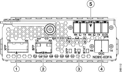
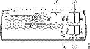
The optical amplifier module (NCS1K-EDFA) has pre-amplifier and booster amplifier.

The optical amplifier module provides the following functionality.

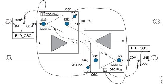
  • Preamplifier (LINE-RX to COM-TX) - Single preamplifier variant, with switchable gain ranges, according to link loss:

    • Range # 1: 0 to 24 dB gain, Tilt control: 24 to 27 gain, with tilt uncontrolled

    • Range # 2: 20 to 34 dB gain, Tilt control: 34 to 37 dB gain, with tilt uncontrolled

    • 23dBm output power @ COM-TX port

  • Booster amplifier (COM-RX to LINE-TX) - True variable gain booster amplifier

    • Gain range: 1 to 20. 20 to 25 uncontrolled tilt.

    • 23dBm output power @ LINE-TX port

  • ADD/DROP OSC channel supports both 1510nm and 1610nm +/-10nm

  • OCM assesses channel presence and Gain regulation and per channel power monitoring.

Figure 1. EDFA Front View

EDFA Front View

1

XFP for OSC and additional OTDR feature

2

SFP for OSC (Optical Service Channel)

3

Status LED

4

Service Channel input and output port [OSC - RX, TX]

5

PRE and BST amplifier inputs and output ports

[L (LINE) - RX, TX]

[C (COM) - RX, TX]

[COM - TX CHECK]

The following table describes the mapping of controllers and optical ports for the optical amplifier module.

Controller

Optical Ports

Ots 0/slot/0/0

  • COM-RX (booster input)

  • COM-TX (preamplifier output)

Ots 0/slot/0/1

  • LINE-RX (preamplifier input)

  • LINE-TX (booster output)

Ots 0/slot/0/2

  • OSC-RX

  • OSC-TX

Ots 0/slot/0/3

COM-CHECK

Amplifier Configuration

NCS 1001 supports two methods to control amplifiers.

  • Manual-All the amplifier settings are controlled by the user.

  • Automatic-All the amplifier settings are controlled by the internal amplifier power regulator.

UDC Port Configuration

There are three UDC RJ-45 ports on the faceplate of NCS 1001. Each port is statically associated with a slot (UDC1 to slot 1, UDC2 to slot 2 and UDC3 to slot3). UDC ports are one Gigabit Ethernet ports and the user can transmit any Ethernet traffic into these ports.

UDC traffic flows through the line, added and dropped by the OSC add/drop filters in the optical amplifier module (NCS1K-EDFA). UDC traffic flows through the line tagged. The tagging and untagging operations are performed by NCS 1001, based on the UDC VLAN specified in the configuration, without any limit on the transmitted traffic. The traffic can be tagged, multiple tagged, or untagged. However, 100% utilization cannot be achieved because four bytes of tag are added to each packet.

UDC Application for Remote Management

The following diagrams describe the application of UDC that can be used by EPNM to manage NCS 1000 series at the remote site.

Figure 2. UDC Application for Remote Management - Scenario One
UDC Application for Remote Management
Figure 3. UDC Application for Remote Management - Scenario Two
UDC Application for Remote Management

Configure Amplifier Module

configure

hw-module location 0/RP0/CPU0 slot slot-number ampli

node-type value

grid-mode value

udc-vlan value

commit

end

Example

The following is a sample in which the amplifier module is inserted in slot 3 and udc-vlan is set to 4000.


configure
hw-module location 0/RP0/CPU0 slot 3 ampli
   [
       grid-mode 100GHz
       udc-vlan 4000
   ]

Amplifier Module Configuration Parameters

Table 2. Amplifier Module Configuration Parameters

Parameter

Description

Range/Values

Default

grid-mode

Defines the optical spectrum on the interfaces of the amplifier module.

  • 100GHz-Configures the amplifier with 100GHz grid of channels with 48 channel spacing.

  • 50GHz-Configures the amplifier with 50GHz grid of channels with 96 channel spacing.

  • 75GHz-Configures the amplifier with 75GHz grid of channels with 64 channel spacing.

    Note


    The new optical passive multiplexer and de-multiplexer module, NCS1K-MD-64-C, introduced in R7.3.1, allows you to configure the amplifier with 75GHz grid of channels.

  • gridless-Configures the amplifier in the flex spectrum.

50GHz

node-type

Defines the type of the node in which the amplifier is set to work.

TERM, ILA

TERM

udc-vlan

Defines the VLAN associated to the selected slot and its UDC port.

2 to 4080

Configure Flex Channels on the Amplifier Module

You can optimize the optical spectrum and granularity using the gridless configuration. In gridless configuration, the fixed ITU-T grid that defines specific channel frequencies and channel widths is not taken into account. You can provision channels with arbitrary channel frequencies and channel widths. You can configure up to 96 channels using the gridless configuration.


Note


Automatic Power Control (APC) regulation in gridless configuration is based on controller ampli-channel-psd parameter.


configure

hw-module location 0/RP0/CPU0 slot slot-number ampli grid-mode gridless

hw-module location 0/RP0/CPU0 slot slot-number ampli flex-chan-id channel-id chan-central-freq frequency chan-width width

commit

end


Note


The new channel is configured only if it does not overlap with the existing channel.


Table 3. Flex Channel Configuration Parameters

Parameter

Description

Range/Values

flex-chan-id

Defines the channel identifier.

1 to 96

chan-central-freq

Defines central frequency of the channel.

191350 to 196100 in multiples of 125

chan-width

Defines the width of the channel.

500 (50.0 GHz) to 8000 (800.0 GHz) in multiples of 12.5 GHz

Example

The following is a sample in which the amplifier module is configured in flex spectrum.


configure
hw-module location 0/RP0/CPU0 slot 2 ampli grid-mode gridless
hw-module location 0/RP0/CPU0 slot 2 ampli flex-channel-id 5 
chan-central-freq 1931750 chan-width 6500
commit
end

The following sample shows the configured channel with its frequency and width.

RP/0/RP0/CPU0#show controllers ots-och 0/2/0/0/5 summary


Fri Oct  9 10:43:44.002 CEST
 Port       	Type   Status   TX Power   RX Power   
                            	  (dBm)      (dBm)    
----------------- -----   -------   ---------  ---------
Ots-Och0_2_0_0_5    Com     N/A     -8.60       -8.90      
TX psd     RX psd         Central         Channel Width
(nW/MHz)   (nW/MHz)       Frequency(GHz)    (GHz)
---------  ------------   -------------    --------------   
  0.410       0.450         193175.0         650.0
RP/0/RP0/CPU0#show controllers ots-och 0/2/0/0/5

Fri Oct  9 10:46:33.046 CEST

 Controller State: Up

 Transport Admin State: Maintenance

 Port Type: Com

 Laser State: Unknown

 Optics Status::


         Alarm Status:
         -------------
         Detected Alarms: None


         Alarm Statistics:
         -----------------
         LOW-RX-PWR = 0
         LOW-TX-PWR = 0
         RX-LOS-P = 0
         RX-LOC = 0
         AMPLI-GAIN-DEG-LOW = 0
         AMPLI-GAIN-DEG-HIGH = 0
         AUTO-LASER-SHUT = 0
         AUTO-POW-RED = 0
         AUTO-AMPLI-CTRL-DISABLED = 0
         AUTO-AMPLI-CFG-MISMATCH = 0
         SWITCH-TO-PROTECT = 0
         AUTO-AMPLI-CTRL-RUNNING = 0

         Parameter Statistics:
         ---------------------
         TX Power = -8.60 dBm
         RX Power = -8.90 dBm
         TX psd = 0.440 nW/MHz
         RX psd = 0.450 nW/MHz
         Channel Central Frequency = 193175.0 GHz
         Channel Width = 650.0 GHz

         Configured Parameters:
         ------------------------
         Rx Low Threshold = -25.0 dBm
         Tx Low Threshold = -25.0 dBm

Modify Central Frequency and Channel Width on the Amplifier Module

You can change the central frequency, channel width, or both for a configured channel ID. The channel ID cannot be arbitrarily changed before unconfiguring the channel.

Example

The following sample changes the central frequency of the channel.


hw-module location 0/RP0/CPU0 slot 1 ampli flex-channel-id 24 
chan-central-freq 1949000 chan-width 500

The following sample changes the channel width for the same channel.

hw-module location 0/RP0/CPU0 slot 1 ampli flex-channel-id 24 
chan-central-freq 1949000 chan-width 1500

The following sample changes both the central frequency and channel width of the channel.

hw-module location 0/RP0/CPU0 slot 1 ampli flex-channel-id 24 
chan-central-freq 1932625 chan-width 6125

In-Line Amplifier

The optical amplifier module (NCS1K-EDFA) can be configured in In-line amplifier (ILA) mode. ILA mode is used when it is not possible to connect to terminal nodes with a single span. ILA mode is supported only in slots 1 and 3.

ILA mode supports only the operation of preamplifier in the two directions. The booster module is switched off in ILA mode. ILA mode supports gain range 1 and 2 of the preamplifier and provides 23dBm output power pre-amplification.

In the ILA mode, the LINE-RX and COM-TX ports of the optical amplifier module are enabled whereas the LINE-TX and COM-RX ports of the optical amplifier module are disabled. OCM reports LINE-RX and COM-TX port values whereas LINE-TX and COM-RX port values are set to -40.00 dBm. In the ILA mode, the LINE-RX terminates on the LINE-RX on the optical amplifier module whereas the LINE-TX terminates on the external OSC module (15216-FLD-OSC=).

Figure 4. ILA Optical Diagram
ILA Optical Diagram

Configure Amplifier Module in ILA Manual Mode

When the amplifier is set to ILA, all the configurations are performed only on the pre-amplifier. After the node is set to ILA, the amplifier gain, RX-low threshold, and the amplifier tilt can be configured on the pre-amplifier.

configure

hw-module location 0/RP0/CPU0 slot slot-number ampli node-type value

commit

end

controller controllertype Rack/Slot/Instance/Port

ampli-control-mode {automatic | manual}

ampli-gain value

rx-low-threshold value

ampli-tilt value

commit

end

Example

The following is a sample in which the amplifier module is configured in ILA manual mode. The node type is set to ILA. This parameter switches off the booster side and activate safety between slots 1 and 3.


configure
      hw-module location 0/RP0/CPU0 slot 3 ampli node-type iLA
      commit
      end
      controller ots 0/3/0/0
      ampli-control-mode manual
      ampli-gain 200
      rx-low-threshold -300
      ampli-tilt -10
      commit
end
   

Configure Amplifier Module in ILA Automatic Mode

The configurations performed on the amplifier module in ILA automatic mode are similar to the configurations performed on the terminal node. The configurations are performed only on the pre-amplifier as the booster is switched off in ILA mode.

configure

hw-module location 0/RP0/CPU0 slot slot-number ampli

grid-mode value

node-type value

commit

end

controller controllertype Rack/Slot/Instance/Port

ampli-control-mode {automatic | manual}

ampli-channel-power value

ampli-tilt value

rx-low-threshold value

channel-power-max-delta value

ampli-gain value

ampli-gain-range {normal | extended}

commit

end

Example

The following is a sample in which the amplifier module is configured in ILA automatic mode.


configure
      hw-module location 0/RP0/CPU0 slot 3 ampli
      grid-mode 50GHz
      node-type iLA
      commit
      end
      controller ots 0/3/0/0
      ampli-control-mode automatic
      ampli-channel-power 30
      ampli-tilt -10
      rx-low-threshold -331
      ampli-gain 220
      ampli-gain-range extended
      commit
end
   

The following is a sample of show running-config command.


line console
exec-timeout 0 0
!
line default
exec-timeout 0 0
session-timeout 0
!
ntp
server 10.58.228.1
update-calendar
!
hw-module location 0/RP0/CPU0 slot 1
ampli udc-vlan 11
ampli grid-mode 50GHz
ampli node-type ILA
!
hw-module location 0/RP0/CPU0 slot 3
ampli udc-vlan 10
ampli grid-mode 50GHz
ampli node-type ILA
!
interface MgmtEth0/RP0/CPU0/0
ipv4 address 10.58.229.143 255.255.252.0
!
interface MgmtEth0/RP0/OSC1/0
shutdown
!
interface MgmtEth0/RP0/OSC2/0
shutdown
!
interface MgmtEth0/RP0/OSC3/0
shutdown
!
controller Ots0/1/0/0
ampli-tilt -12
ampli-control-mode automatic
ampli-channel-power 22
channel-power-max-delta 45
!
controller Ots0/1/0/1
rx-low-threshold -250
!
controller Ots0/3/0/0
ampli-tilt -12
ampli-control-mode automatic
ampli-channel-power 22
channel-power-max-delta 45
!
controller Ots0/3/0/1
rx-low-threshold -250
!
router static
address-family ipv4 unicast
  0.0.0.0/0 10.58.228.1
!
!
netconf-yang agent
ssh
!
ssh server v2
end

Gridless OCM Support

Overview

The Gridless OCM (Optical Channel Monitor) support feature is introduced to support transponders with channel width between 50GHz to 100GHz. In R7.1.1, the channel width can be set between 50GHz to 800GHz in multiples of 25GHz. In the gridless mode, the amplifier gain is calculated using the power spectral density parameter and not the per channel power parameter. The flex grid provides the capability to support 600G interface of NCS 1004.

Limitation

  • The setting of a channel width disables the nearest channels.

Configure the Channel Width

The channel width can be set between 1000 and 8000.

The following command configures the channel width as 100GHz. This means that the channels are spaced on eight slices at 12.5GHz each.


hw-module location 0/RP0/CPU0 slot 1 ampli flex-mode flex-spectrum
channel-id 1 channel-width 1000

The following command configures the channel width as 800GHz. This means that the channels are spaced on eight slices at 100GHz each.


hw-module location 0/RP0/CPU0 slot 1 ampli flex-mode flex-spectrum
channel-id 10 channel-width 8000

Protection Switching Module

The protection switching module (NCS1K-PSM) provides the following functionality.

  • In TX section:

    • Splits input optical channels to both working and protection lines.

    • Forces the switch in the remote site by opening one of the two line paths (by putting the related VOA in AVS).

  • In RX section:

    • Selects the signals from working or protection line. Each line is monitored through a PD.

    • Balances the two line losses by changing the VOA attenuation value at the same time of the switch change of state.

Figure 5. PSM Front View

PSM Front View

1

Protected path input and output port [P - RX, TX]

2

Working path input and output port [W - RX, TX]

3

COM input and output port [COM - RX, TX]

4

Status LED

The following table describes the mapping of controllers and optical ports for the protection switching module.

Controller

Optical Ports

Ots 0/slot/0/0

COM-TX

Ots 0/slot/0/1

Working path input and output port [W - RX, TX]

Ots 0/slot/0/2

Protected path input and output port [P - RX, TX]

Configure Protection Switching Module

The following table explains the possible configuration on Protection Switching Module:

PSM Module Configuration Parameters

Table 4. PSM Module Configuration Parameters

Parameter

Description

Range/Values

lockout-from

Excludes the selected port from protection.

Triggers a switch when the active port is specified in the lockout.

For example, configuring a lockout-from working port triggers a switch to protect when working port is the active one.

While lockout-from protected port triggers a switch to working when protected port is the active one.

Working and Protected

path-protection

Enables the PSM path protection.

section-protection

Enables the PSM section protection.

uni-dir

Enables the PSM uni directional (in switches only).

auto-threshold

Enables the PSM auto threshold setting.

Example

The following is an example of configuration of a lockout from working in which the PSM is inserted in slot 2.


conf t
#hw-module location 0/RP0/CPU0 slot 2 psm lockout-from "working"
commit

You can apply manual switching by using the following command:

hw-module slot slot number manual-switch-to working | protected

The switch by user command from the path without the ILA node in the middle is performed bi-directionally. If the ILA and terminal nodes are in section-protection, the manual and lockout switch command from the path with ILA node in the middle are performed uni-directionally.


Note


FPD upgrade on FW_PSMv1 from FW 1.43 and FW 1.44 to FW 1.45 affects the traffic.


(From R6.2.1) Section Protection

Figure 6. Section Protection Topology
Section Protection Topology

See the PSM Module Configuration Parameters section to set the section-protection parameter on both the PSMs. Ensure that the PSM in a section protection topology is inserted in slot 2. Connect the EDFA in slot 1 to the Protected port of the PSM and EDFA in slot 3 to the Working port of the PSM.


Note


To measure the correct switching time while testing the section protection topology, we recommend you to wait for 120 seconds between two subsequent switching events (or between a switching event and the restoration). This waiting period allows the EDFAs to stabilize after the first switching occurrence, thus avoiding the power at the PSM to oscillate around the threshold.


(From R6.3.2) Path Protection

Figure 7. Path Protection Topology
Path Protection Topology

See the PSM Module Configuration Parameters section to set the path-protection parameter on both the PSMs.

Protection Switching Module with Manual Threshold

The switch can operate in all conditions, if it is set in Autothreshold.

When the path protection is configured with a manual threshold, you must ensure that:

  • During the first installation, the value on the PSM RX-low Threshold should be set as 3 dB below the minimum power for a single channel. The value must ensure that the PSM is able to switch on with a single channel or when the EDFA is in APR (+8 dBm).

  • When the system is up and running with the final number of channels, the PSM RX-low Threshold must be set 3 dB below the target power.

  • After a fiber cut and restore, in order to ensure that the PSM is able to switch on, it is necessary to set the value of PSM RX-low Threshold similar to the value set during the first installation.

The PSM Auto-threshold configuration is highly recommended for a three-way topology.

In a three-way topology, when the path protection is configured with a manual threshold, you must follow the above steps. If you did not configure all the above steps properly, you may encounter the following issues:

  • Switch may not be bidirectional.

  • Double switch on PSM in path protection, when set in three-way configuration.

It is possible to configure parameters such as rx-enable, tx-enable in OTS controllers (1 or 2, i.e. working or protected port) of PSM card.

For more information on OTS controllers, see Configure OTS Controller.

Autothreshold for Protection Switching Module

When auto-threshold is not enabled, the RX-low threshold value active on PSM working and protected RX-ports can either be set by the user or the default values can be used.

The current threshold is the configured parameter if the values set are available in the show controller command output. The current value is -38dBm (default values), if the user doesn’t have configured any value for those parameters.

If auto-threshold is enabled on the PSM, the RX-low thresholds values for port 1 and 2 configured by the user are ignored (current thresholds is not the configured parameter). When the auto threshold is enabled on the PSM card:

  • If optical Power at Working-RX and Protected-RX port is stable (+/- 1 dB) for 2 minutes, related RX-Low threshold is automatically set to RX power – 3dB.

  • If power is not stable, the releated thresholds do not change.

  • W-RX and P-RX are regulated independently.

The LOS-P behavior on the auto-threshold are:

  • When a LOS-P alarm is detected on the working or protected RX-port, in case of auto-threshold is enabled, the related threshold remains the same. This behavior happens when the RX power is less than the related threshold on the RX-port working or protected.

  • When the LOS-P alarm is cleared in the first 30 seconds, the ordinary auto-threshold mechanism is applied. This behavior happens after 2 minutes of stable RX-power and when the RX-low threshold is changed to the new RX power -3 dB.

  • When the LOS-P is present after 30 seconds, the RX-low threshold is automatically moved to the values set by the user.

  • When the LOS-P is cleared, the ordinary auto-threshold mechanism is applied again. This behavior happens when the RX power is higher than the related current threshold.

Configure rx-low-threshold for PSM

You must configure the rx-low-threshold parameter before enabling auto-threshold on PSM.

PSM auto-threshold feature monitors the W-RX/P-RX ports of the PSM module for actual received power. When the received power is stable, the feature sets the rx-low-threshold value of the W-RX/P-RX ports with the current power value. The current value of the threshold is set to 3 dB lower than the received power. If there is LOS at the W-RX/P-RX ports due to fiber cut or temporary disruption of received power, the feature restores the rx-low-threshold value of the W-RX/P-RX ports to the configured value.

RP/0/RP0/CPU0:ios#show controllers ots 0/2/0/1
Parameter Statistics:
-----------------------
         RX Power = -4.00 dBm
         Rx Low Threshold Current = -7.0 dBm   <<< current value (auto-threshold)

Configured Parameters:
-----------------------
         Rx Low Threshold = -38.0 dBm <<< configured value (user configured)

We recommend to configure both the rx-low-threshold and auto-threshold values of the PSM module according to the following guidelines:

Configure PSM W/RX Threshold (Ots0_2_0_1/Working) with Amplifier Control Mode as Manual

  1. show hw-module slot 3 channel-trail-view active

    
    Channel Trail View - Active - dBm
    ===========================================
                                                                  BST: 0/COM=>1/LINE              PRE: 1/LINE=>0/COM
    Och Name       Wavelength(nm)Freq(GHz) Width(GHz)Rx pwr(dBm) Tx pwr(dBm) Rx pwr(dBm)  Tx pwr(dBm)
    ------------------------------------------------------------------------------------------------------------------------
    Ots-Och0_2_0_0_1  1528.77    196100.0    50.0     -6.10       -4.90       -2.50         6.20
    Ots-Och0_2_0_0_2  1529.16    196050.0    50.0     -5.90       -4.60       -2.20         6.50
    Ots-Och0_2_0_0_3  1529.55    196000.0    50.0     -6.00       -4.80       -2.30         6.30
    Ots-Och0_2_0_0_4  1529.94    195950.0    50.0     -6.10       -4.90       -2.40         6.20
    Ots-Och0_2_0_0_5  1530.33    195900.0    50.0     -6.30       -5.20       -2.60         6.00
    Ots-Och0_2_0_0_6  1530.72    195850.0    50.0     -6.50       -5.30       -2.80         5.90
    

    Examine the PRE: 1/LINE=>0/COM column in the command output and choose the lowest channel Tx pwr value from all the active channels.

  2. configure

  3. controller ots 0/2/0/1 rx-low-threshold 49

    Set the threshold value manually to (lowest channel Tx power – 1 dBm). In the above example, channel Ots-Och0_2_0_0_6 is at the lowest Tx power 5.90 dBm. Hence, the threshold value on PSM W/RX port will be 5.90 – 1 = 4.90 dBm.

If the system works without any grid mode configuration, the channel-trail-view command is not available because channel mapping configuration is not available.

To identify the lowest channel Tx pwr value, use the following show command.

show controllers ots0/3/0/0 spectrum-info


Tx power :
 ----------------------------------------------------------------------------------
 spectrum-slice num                        Tx-power values (dBm)
 ----------------------------------------------------------------------------------
   1 - 8               -47.20 -47.20 -47.20 -36.40     -47.20 -47.20 -47.20 -47.20
   9 - 16              -47.20 -47.20 -43.70 -43.70     -47.20 -36.60 -47.20 -43.20
  17 - 24              -47.20 -35.80 -47.20 -47.10     -41.90 -43.20 -42.20 -40.30
  25 - 32              -40.30 -47.20 -41.70 -41.70     -37.50 -47.20 -47.20 -41.90
  33 - 40              -41.90 -47.20 -45.90 -42.10     -42.10 -46.30 -41.60 -39.10
  41 - 48              -41.20 -47.20 -35.80 -45.10     -45.30 -45.30 -40.10 -40.10
  49 - 56              -45.50 -42.60 -45.30 -47.20     -47.20 -40.50 -47.20 -45.80
  57 - 64              -38.60 -40.30 -40.30 -47.20     -47.20 -39.40 -43.10 -43.10
  65 - 72              -42.20 -42.20 -47.20 -47.20     -38.80 -47.20 -47.20 -41.30
  73 - 80              -47.20 -43.00 -40.10 -40.10     -47.20 -36.10 -39.40 -45.70
  81 - 88              -47.20 -41.50 -39.00 -42.50     -47.20 -47.20 -34.30 -47.20
  89 - 96              -47.20 -47.20 -39.90 -39.70     -47.20 -47.20 -47.20 -47.20
  97 - 104             -47.20 -45.10 -39.90 -41.30     -47.20 -39.80 -37.80 -42.00

All the slice power values are expressed in PSD (Power Spectral Density) units of measure [dBm/12.5GHz]. Each slice value is converted to linear mWatt using the formula 10^(N/10). For example, -20 dBm = 10^(-20/10) = 0.01 mWatt and 0 dBm = 10^0 = 1 mWatt.

Each slice group that composes a channel will be algebraically added to obtain the integral channel power. For example, the first channel of 50GHz occupies the slice range [1-4], 2nd channel [5-8] and so on. The first channel of 75GHz occupies the slice range [1-5],[6-11] and so on. The first channel of 100 GHz occupies the slice range [1-6],[7-14] and so on.

Each channel power that falls below the rx-low-threshold value is excluded from the list of active channels. The channel that has the least value above the rx-low-threshold value is chosen.

Configure PSM P/RX Threshold (Ots0_2_0_2/Protected) with Amplifier Control Mode as Manual

  1. show hw-module slot 1 channel-trail-view active

    
    Channel Trail View - Active - dBm
    ===========================================
                                                                  BST: 0/COM=>1/LINE              PRE: 1/LINE=>0/COM
    Och Name      Wavelength(nm)Freq(GHz) Width(GHz)Rx pwr(dBm) Tx pwr(dBm)  Rx pwr(dBm)  Tx pwr(dBm)
    ------------------------------------------------------------------------------------------------------------------------
    Ots-Och0_2_0_0_1 1528.77    196100.0    50.0     -6.10       -4.90        -2.50         5.00
    Ots-Och0_2_0_0_2 1529.16    196050.0    50.0     -5.90       -4.60        -2.20         5.20
    Ots-Och0_2_0_0_3 1529.55    196000.0    50.0     -6.00       -4.80        -2.30         5.10
    Ots-Och0_2_0_0_4 1529.94    195950.0    50.0     -6.10       -4.90        -2.40         5.00
    Ots-Och0_2_0_0_5 1530.33    195900.0    50.0     -6.30       -5.20        -2.60         5.00
    Ots-Och0_2_0_0_6 1530.72    195850.0    50.0     -6.50       -5.30        -2.80         4.80
    

    Examine the PRE: 1/LINE=>0/COM column in the command output and choose the lowest channel Tx pwr value from all the active channels.

  2. configure

  3. controller ots 0/2/0/2 rx-low-threshold 38

    Set the threshold value manually to (lowest channel Tx power – 1 dBm). In the above example, channel Ots-Och0_2_0_0_6 is at the lowest Tx power 4.80 dBm. Hence, the threshold value on PSM W/RX port will be 4.80 – 1 = 3.80 dBm.

Configure PSM W/RX Threshold (Ots0_2_0_1/Working) with Amplifier Control Mode as Automatic

  1. show controllers ots 0/3/0/0

    
    Configured Parameters:
    
    -------------------------
             Ampli Channel power = 0.00 dBm
    

    Examine the ampli-channel-power Tx value in the command output.

  2. configure

  3. controller ots 0/2/0/1 rx-low-threshold -10

    Set the threshold value manually to (ampli-channel-power – 1 dBm). In the above example, ampli-channel-power Tx value is 0 dBm. Hence, the threshold value on PSM W/RX port will be 0 – 1 = -1 dBm.

Configure PSM P/RX Threshold (Ots0_2_0_2/Protected) with Amplifier Control Mode as Automatic

  1. show controllers ots 0/1/0/0

    
    Configured Parameters:
    
    -------------------------
             Ampli Channel power = 2.00 dBm
    

    Examine the ampli-channel-power Tx value in the command output.

  2. configure

  3. controller ots 0/2/0/2 rx-low-threshold 10

    Set the threshold value manually to (ampli-channel-power – 1 dBm). In the above example, ampli-channel-power Tx value is 2 dBm. Hence, the threshold value on PSM W/RX port will be 2 – 1 = 1 dBm.

Enable Autothreshold for PSM

Before You Begin

Configure rx-low-threshold for PSM

This procedure enables automatic thresholds for PSM. The configuration to set auto threshold mechanism are:

configure

hw-module location 0/RP0/CPU0 slot slot number psm auto-threshold

commit

end

slot number is the slot where the PSM is inserted.

Example

The following is a sample for enabling autothreshold on a PSM equipped in slot 1.

RP/0/RP0/CPU0:MYS-237#configure terminal 
RP/0/RP0/CPU0:MYS-237(config)#hw-module location 0/RP0/CPU0 slot 1 psm auto-threshold 
RP/0/RP0/CPU0:MYS-237(config)#commit
eRP/0/RP0/CPU0:MYS-237(config)#end

Configure Relative Switch Threshold for PSM

Relative switch threshold allows you to manually configure the delta threshold on PSM at which the working path switches to the protected path. Relative switch threshold can be configured on PSM only if auto-threshold or revertive wtr are not configured. You can configure the relative switch threshold using the following commands:

configure terminal

hw-module location 0/RP0/CPU0 slot slot number psm relative-switch-threshold value relative-switch-threshold-offset value

commit

end

For more information about these commands, see Command Reference for Cisco NCS 1001.

Example

RP/0/RP0/CPU0:MYS-237#configure terminal 
RP/0/RP0/CPU0:MYS-237(config)#hw-module location 0/RP0/CPU0 slot 1 psm relative-switch-threshold 120 relative-switch-threshold-offset -150 
RP/0/RP0/CPU0:MYS-237(config)#commit
eRP/0/RP0/CPU0:MYS-237(config)#end

Automated OTS-OCH Thresholds on Amplifier

The automated OTS-OCH thresholds can be enabled or disabled on each EDFA (Erbium Doped Fiber Amplifier) card equipped on the node itself. It applies on the EDFA OTS controllers and on all the related OTS-OCH controller ports.

When the automatic threshold function is enabled on the amplifier, the threshold value to set is determined using the following formula:

rx-low-threshold = (Remote AmplChannel - RXSpanloss )-User Threshold Offset.

Where

Remote AmplChannel is the ampli channel power set on the remote node for ots controller tx port of remote EDFA.

RXSpanloss is the RX Span Loss calculated on the local node.

User Threshold Offset is the ampli-auto-rxlow-threshold threshold-offset set on the local node for EDFA in slot 1.

Any modification to each of the parameters included in the formula does not automatically account for the calculation of the rx-low threshold value. To calculate a different rx-low-threshold value correspondingly, you must execute the following CLI command:

hw-module slot<n>ampli-auto-rxlow-threshold threshold-offset <value>

Example: hw-module slot 1ampli-auto-rxlow-threshold threshold-offset 400

Command Parameters:

  • <n> (1,2 3): This parameter designates the specific slot where the EDFA card is installed within the device.

  • <value> ( 0-800): This parameter represents the desired adjustment to the Amplifier RX-LOW threshold, specified in tenths of dBm.

Limitations

  • This feature works, only if the user has configured span loss calculation. Refer Span Loss Calculation section in the Configure Controllers chapter of the configuration guide.

Configure Automatic Thresholds

This procedure enables automatic thresholds for EDFA. The configuration to set automatic threshold mechanism are:

configure terminal

hw-module location 0/RP0/CPU0 slot slot number ampli auto-threshold

commit

end

slot number is the slot where the EDFA is inserted.

Example

The following is a sample for enabling autothreshold on an EDFA inserted in slot 1.

RP/0/RP0/CPU0:MYS-237#configure terminal 
RP/0/RP0/CPU0:MYS-237(config)#hw-module location 0/RP0/CPU0 slot 1 ampli auto-threshold 
RP/0/RP0/CPU0:MYS-237(config)#commit
eRP/0/RP0/CPU0:MYS-237(config)#end

Verification

The following is a sample for checking whether the auto-threshold is configured.

#show running hw-module location 0/RP0/CPU0 slot 1 ampli
….
 ampli span-loss
 ampli node-type TERM
 ampli remote-node local-ipv4 10.58.xxx.xxx remote-ipv4 10.58.xxx.xxx remote-slot-id 3
 ampli auto-threshold

PSM Virtual Photodiode

Protection Switching Module (PSM) Virtual diode provides an optical power reading even if photodiodes are not available. PSM does not have photodiode on COM-RX. There are two photodiodes on Working-TX and Protected-TX present after the VOA.

The value of power on Com-RX is real, if at least one value between the W-TX and the P-TX power is not equal to -40 dB (related port in AVS).

When both the power of W-TX and P-TX are equal to -40dB (both related VOA in AVS-Automatic VOA Shutdown), it is impossible to calculate the real power on Com-RX port, and the value will be shown as -40dB.

The feature does not require any configuration. There is a change only in the show controllers ots 0/<slot>/0/0 command, which shows the RX power on Com-RX port. RX low power alarm is not managed on Com-RX port.

Example for show controller

RP/0/RP0/CPU0:ios#show controllers ots 0/2/0/0


Wed Jan 24 14:33:22.898 CET

 Controller State: Up 

 Transport Admin State: In Service 

 Port Type: Com 

 Laser State: Unknown 

 Optics Status:: 


 Alarm Status:
 -------------
 Detected Alarms: None


 Alarm Statistics:
 -----------------
 LOW-RX-PWR = 0 
 LOW-TX-PWR = 0 
 RX-LOS-P = 0 
 RX-LOC = 0 
 AMPLI-GAIN-DEG-LOW = 0 
 AMPLI-GAIN-DEG-HIGH = 0 
 AUTO-LASER-SHUT = 0 
 AUTO-POW-RED = 0 
 AUTO-AMPLI-CTRL-DISABLED = 0 
 AUTO-AMPLI-CFG-MISMATCH = 0 
 SWITCH-TO-PROTECT = 0 
 AUTO-AMPLI-CTRL-RUNNING = 0 

 Parameter Statistics:
 ---------------------
 TX Power = 15.30 dBm 
 RX Power = 5.30 dBm 
 tx-enable = 1 
 rx-enable = 1 

 Configured Parameters:
 -------------
 tx-enable = 1 
 rx-enable = 1 

PSM 3-way Protection

NCS 1001 supports Protection Switching Module (PSM) 3-way protection scheme formed by combining a Section Protection scheme with a Path Protection scheme. There is no confiugration change required in PSM to implement the PSM 3- way protection scheme. The Path Protection scheme is in the middle of one of the two paths of Section Protection scheme.

For the outer section protection it is suggested to use the PSM automatic threshold configuration.

Figure 8. 3-way Protection Network Topology
Figure 9. 3-way Protection Network Topology

The 3-way Protection Scheme has the following limitations:

  • For each PSM switching the bi-directionality is not definite.

  • The manual switching used to change the active path is sometimes unsuccessful.

The lockout configuration is recommended to control the switching operation from one path to another on all the 4 PSMs of the protection scheme. The lockout configuration must be applied on both local and corresponding remote PSM to ensure the bi-directionality.

PSM Revertive Switch

When an LOS (Loss of Signal – Payload) alarm occurs on the primary path due to fiber cut, traffic moves from primary to secondary path. PSM revertive switch features allows the traffic to move to the primary path from secondary path when the fiber cut is resolved and the LOS alarm is cleared on the primary path. The traffic switch to the primary path is not immediate and depends on the following parameters.

Parameters of PSM Revertive Switch

  • WTR (Wait To Restore Time): WTR is the time delay (in seconds) introduced after LOS alarm on the primary path is cleared. When WTR timer elapses, traffic moves to the primary path.

  • Threshold hysteresis: Threshold hysteresis parameter is required to avoid transient or flipping power readings in the region near the threshold which is monitoring the primary rx port.

    Threshold hysteresis parameter, if set, works in combination with WTR timer. After the fiber cut is fixed and alarm is cleared, the system starts the WTR timer only when the power on primary rx port becomes higher than the sum of rx-low-threshold and threshold hysteresis (rx-low-threshold-delta) values. When WTR timer elapses, traffic moves to the primary path.


Note


The suggested values for WTR and threshold hysteresis parameters are 120 seconds and 1.0 dBm respectively. Both the parameter values must be properly chosen based on different conditions such as power received, type of PSM protection scheme, manual threshold values provisioned on PSM or auto-threshold enabled, and so on.


Limitations

  • PSM revertive switch feature is supported only on section protection or path protection schemes.

  • PSM revertive switch feature is not supported on PSM 3-way protection scheme.

  • PSM revertive switch feature is not supported on section protection or path protection schemes involving one or more ILA nodes.

  • PSM revertive switch feature works only in case of switch from primary to secondary path due to fiber cut and not in case of switch from primary to secondary path due to user commands such as manual-to or lock-out-from.

Configure PSM Revertive Switch

configure

hw-module location 0/RP0/CPU0 slot slot-number psm

revertive wtr wtr-value

primary-path path

commit

end

wtr-value must be an integer. The primary path is set to WORKING by default. The user can change this path from WORKING to PROTECTED but cannot delete it.

Example

The following is a sample of configuring the WTR parameter of PSM revertive switch in which the PSM module is inserted in slot 2 and primary path is set to working.


configure
hw-module location 0/RP0/CPU0 slot 2 psm
revertive wtr 120
primary-path WORKING
commit
end
   

The following is a sample of configuring the threshold hysteresis parameter of PSM revertive switch.


configure terminal
controller 0/2/0/1 rx-low-threshold-delta 10
commit
end

rx-low-threshold-delta is the threshold hysteresis. The value 10 is expressed in units of 0.1 dBm. In the above example, the value of threshold hysteresis is set as 1.0 dBm.

Example of show controller

RP/0/RP0/CPU0:ios# show controllers ots 0/2/0/1


Controller State: Up 

 Transport Admin State: In Service 

 Port Type: Working 

 Port Status: Standby 

 Laser State: Unknown 
 
 Optics Status:: 

         Alarm Status:
         -------------
         Detected Alarms: 
                 
         Alarm Statistics:
         -----------------
         LOW-RX-PWR = 0          
         LOW-TX-PWR = 0          
         RX-LOS-P = 735        
         RX-LOC = 0          
         AMPLI-GAIN-DEG-LOW = 0          
         AMPLI-GAIN-DEG-HIGH = 0          
         AUTO-LASER-SHUT = 0          
         AUTO-POW-RED = 0          
         AUTO-AMPLI-CTRL-DISABLED = 0          
         AUTO-AMPLI-CFG-MISMATCH = 0          
         SWITCH-TO-PROTECT = 4          
         AUTO-AMPLI-CTRL-RUNNING = 0          
          
         Parameter Statistics:
         ---------------------
         TX Power = -16.70 dBm 
         RX Power = -21.00 dBm 
         RX Voa Attenuation = 0.00 dB 
         TX Voa Attenuation = 0.00 dB 
         TX Enable = Enabled 
         RX Enable = Enabled 
         Rx Low Threshold Current = -38.0 dBm 
         Wait Time to Restore = 120 secs 
          
          
         Configured Parameters:
         -------------
         Rx Low Threshold = -38.0 dBm 
         RX Voa Attenuation = 0.0 dB 
         TX Voa Attenuation = 0.0 dB 
         TX Enable = Enabled 
         RX Enable = Enabled 
         Rx Low Threshold Delta = 1.0 dBm

OSC

OSC (Optical Service Channel) is an out-band channel added and dropped into the optical amplifier module. The wavelengths supported by OSC are 1510 nm and 1610 nm.

OSC provides a communication channel for the following types of traffic.

  • Traffic coming from a UDC port

  • Traffic for remote management of NCS 1001

Remote Management

Remote Management feature, introduced in R6.3.1, allows to configure the IP addresses of the local and remote nodes, to remotely manage NCS 1001.

Three OSC interfaces are configured to support remote management. The OSC interfaces are configured to provide static routes to remote nodes. Each OSC interface is statically associated with a slot (OSC1 to slot 1, OSC2 to slot 2, and OSC3 to slot3).

Configuration Steps

  1. Configure management and OSC interfaces

  2. Configure static routes

Network Topology Discovery

Network topology discovery feature based on OSPF protocol, introduced in R6.3.2, allows to discover NCS 1001 nodes connected to each other through OSC links without configuring the static routes. This feature checks for compatibility only between NCS 1001 nodes.

OSPF must be properly configured on the NCS 1001 nodes by defining the name, router ID, interfaces in the Area 0 section, and optionally, configuring the interfaces as passive. OSPF and OSPFv3 protocols are supported.

The following network topologies are supported.

  • Point to Point

  • Point to Point with ILA nodes (up to three ILA nodes)

Configuration Steps

  1. Configure management and OSC interfaces

  2. Configure OSPF routes

Configure Management and OSC Interfaces

configure

interface mgmtEth rack/slot/instance/port

ipv4 address ipv4-address subnet-mask

shutdown

exit

Example

The following are samples of configuring the management and OSC interfaces.


configure
interface MgmtEth 0/RP0/CPU0/0
ipv4 address 10.58.227.198 255.255.255.0
shutdown
exit

configure
interface MgmtEth 0/RP0/OSC1/0
ipv4 address 10.1.1.1 255.255.255.0
shutdown
exit

configure
interface MgmtEth 0/RP0/OSC2/0
ipv4 address 10.1.2.1 255.255.255.0
shutdown
exit

configure
interface MgmtEth 0/RP0/OSC3/0
ipv4 address 10.1.3.1 255.255.255.0
shutdown
exit

Configure Static Routes

This procedure configures all the static routes into the NCS 1001 node.

configure

router static address-family ipv4 unicast 0.0.0.0/0 default-gateway

exit

Example

The following sample shows the NCS 1001 node connected to three different nodes using static routes.


configure
router static address-family ipv4 unicast
0.0.0.0/0 MgmtEth 0/RP0/CPU0/0 10.58.227.1
10.1.1.0/24 MgmtEth 0/RP0/OSC1/0 10.1.1.2
10.1.2.0/24 MgmtEth 0/RP0/OSC2/0 10.1.2.2
10.1.3.0/24 MgmtEth 0/RP0/OSC3/0 10.1.3.2
exit

Configure OSPF Routes

configure

router ospf process-id

router-id ip-address

area area-id

exit

Example

The following is a sample of configuring OSPF routes.


configure
interface MgmtEth0/RP0/CPU0/0
 ipv4 address 10.1.1.2 255.255.255.0
!
interface MgmtEth0/RP0/OSC1/0
 shutdown
!
interface MgmtEth0/RP0/OSC2/0
 ipv4 address 10.1.3.2 255.255.255.0
!
interface MgmtEth0/RP0/OSC3/0
 ipv4 address 10.1.4.2 255.255.255.0
!
router ospf remote
 router-id 10.1.1.2
 area 0
  interface MgmtEth0/RP0/CPU0/0
   passive enable
  !
  interface MgmtEth0/RP0/OSC2/0
  !
  interface MgmtEth0/RP0/OSC3/0
  !
 !
!
end

Verify OSPF Routing Table

RP/0/RP0/CPU0:ios# show ospf routes


Sat Jul 29 09:54:25.937 UTC

Topology Table for ospf local with ID 10.1.4.1

Codes: O - Intra area, O IA - Inter area
       O E1 - External type 1, O E2 - External type 2
       O N1 - NSSA external type 1, O N2 - NSSA external type 2

O    10.1.1.0/24, metric 1
       10.1.1.2, directly connected, via MgmtEth0/RP0/CPU0/0
O    10.1.3.0/24, metric 1
       10.1.3.2, directly connected, via MgmtEth0/RP0/OSC2/0
O    10.1.7.0/24, metric 2
       10.1.3.1, from 10.58.227.198, via MgmtEth0/RP0/OSC2/0
O    10.58.227.0/24, metric 1
       10.1.3.1, from 10.58.227.198, via MgmtEth0/RP0/OSC2/0

Troubleshooting Network Issues

Troubleshooting must be performed by checking the status of the interfaces, subnets, static routing, and OSPF sections.

Problem

Command

Interfaces are in down state

show interfaces MgmtEth rack/slot/instance/port

Route to default gateway is not defined

show running-config

Wrong IP addresses or subnet are planned in design phase

show running-config

Wrong static routes are defined that overwrite OSPF routes

Compare the output of show ip route command with show ospf routes command

Interfaces are not added in the OSPF section configured

show running-config

Interfaces are in passive mode in the OSPF section configured

show running-config