Cisco NCS 4206 Features
The Cisco NCS 4206 has the following hardware features:
- 3-RU modular chassis designed for installation in a 23-inch EIA rack
- Dedicated slots in the
chassis that support the following:
- Up to six interface modules
- Up to two Route Switch Processors (RSP)
- Up to two DC power supply units
- One fan tray
- Network frequency, phase, and time inputs and outputs for network interfaces (SyncE and TDM), BITS, 1 PPS or 10 MHz and Timing over Packet (IEEE 1588-2008)
- Adjustable front and rear rail mounting locations
- Front panel access to power supplies, fan tray, RSPs, and interface modules
- Online insertion and removal (OIR) of RSP, interface modules, power supplies, and fan tray
- Discrete status LEDs on power supply, interface module, RSP, and fan tray units
- Four alarm dry contact inputs (either normally open or normally closed)
- Environmental monitoring and reporting functions
- LED indicators for critical, major, and minor alarms
- Side-to-side forced air cooling
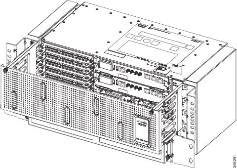
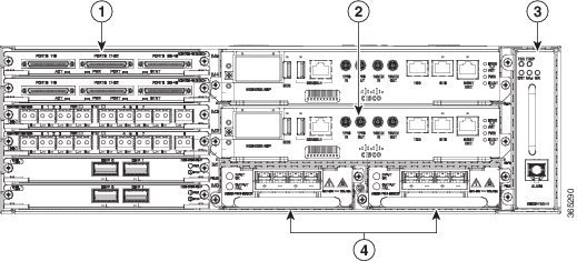
The figure below illustrates the Cisco NCS 4206 chassis design.
|
1 |
Interface modules |
|
2 |
RSP unit |
|
3 |
Fan tray |
|
4 |
Redundant power units (two DC power units are shown) |
Power Supply Features
The Cisco NCS 4206 support DC power supplies. For more information about installing the Cisco NCS 4206 power supplies, see Installing the Power Supply.
To estimate the required power supply, use the Cisco Power Calculator.
The power sections provide more information about the power supply.
Redundancy
The Cisco NCS 4206 chassis includes a slot for an optional redundant power supply. The redundant power supply option provides a second power supply to ensure that power to the chassis continues uninterrupted if one power supply fails or input power on one line fails. Redundancy is supported either with identical power supplies or a combination of DC power supply. The Cisco NCS 4206 supports current sharing between the power supplies.
If you install a redundant power supply on the Cisco NCS 4206, we recommend that you connect each power supply to a separate input power source in order to ensure that the chassis maintains power in the event of a power interruption caused by an electrical failure, a wiring fault, or a tripped circuit breaker.
Status LEDs
LEDs are also provided on each power supply to indicate the status of the input power and the health of the power supply. For more information about the LEDs on the Cisco NCS 4206, see Troubleshooting.
DC Power Specifications
The power supply contains a front panel with mounting screws, a handle for insertion and removal, and two status LEDs. No ON/OFF switch is provided. The power supply is field replaceable and hot-swappable.
The DC power supply model supported on the chassis is:
- A900-PWR900-D2—Provides 900 W output power for system. See the figure below.

The A900-PWR900-D2 DC power supply module comes with a protective front cover.
|
Part numbers |
A900-PWR900-D2 |
|
Input power specification |
48V, GND, –48V |
|
Minimum input voltage |
–40.0 V |
|
Maximum input voltage |
–72 VDC |
|
Input current specification |
22A @–48VDC 18A @–60VDC |
|
Output voltage |
+12 VDC |
|
Wire gauge for DC input power connections |
6 or 8 or 10 AWG for –48/–60 VDC |
|
Maximum power output |
900 W |
For more information on installing the power supply, see Installing DC Power Supply Unit (A900-PWR900-D2).
Fan Tray
The fan tray has the following hardware features:
- It provides side-to-side forced air cooling
- It is field replaceable
- It contains status LEDs
- It contains an alarm port with four external alarm inputs
The fan tray module supported on the chassis is:
- A903-FAN-H
For more information about air flow guidelines, see Air Flow Guidelines. For instructions on how to install the fan tray, see Installing the Fan Tray. For a summary of the LEDs on the fan tray, see LED Summary.
Fan Tray (A903-FAN-H)
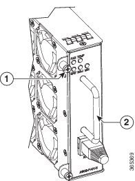
The Cisco NCS 4206 uses a modular fan tray that is separate from the power supply. The fan tray contains twelve fans and provides sufficient capacity to maintain operation indefinitely in the event of an individual fan failure.
|
1 |
Fan tray screw |
2 |
Handle |
Plenum
Plenum or air baffle assembly (see the figure below) is used to change the air flow pattern of the unit. When the chassis is installed with the plenum, the air flow pattern is changed from side-side to front-back. The air flow front-back pattern provides a rack installation bay with a cool front zone and hot rear zone. For installing the plenum, see Installing the Chassis in the Plenum.

 Note |
When the plenum and air filter are installed in the chassis, the system operating temperature is 55 degrees Celsius. |
The air filter must be removed for cleaning or for a replacement.
Air Filter Maintenance
A periodic health check of the filter, every 3 months based on the level of dust in the environment helps in avoiding over clogging of the filters and provide better life. The filter may be used as a single use or reused depending upon the local deployment needs. If reuse of the filter is prohibited, it may be replaced every six months.
If reused, this filter media may be cleaned with slightly compressed air, vacuumed, and/or rinsed with clean water. If a degreaser is required, use only a mild detergent, such as, dish washing liquid.
 Caution |
Avoid using harsh solvents or cleaning agents. |
If filter is cleaned with water, the filter should be completely dry before reinstalling. Even though this type of filter may be cleaned, replacement is recommended every two to three years to ensure media durability and eliminate residual dust build-up and subsequent air flow resistance.
RSP Modules
The Cisco NCS 4206 is designed to use up to two RSP modules to handle the data plane, network timing, and control plane functionalities for the chassis. The RSP configuration allows you to use Cisco IOS software to control chassis management, redundancy, external management, and system status indications on the chassis.
RSP features include:
- Loading software onto processor-based interface modules
- Redundant RSP management—The RSP manages detection of RSPs, exchange of health and status information, role negotiation, function for detection, health and status exchange, role negotiation
- Packet processing
- Traffic management, including buffering, queuing, and scheduling, Ethernet MAC functions
- Network clocking functions including phase and time-of-day for BITS, 1 PPS, 10 MHz, and 1588 PTP clock references
- Storage of software images, system configuration, OBFL, SysLog
- PTP packet processing including IEEE 1588-2008 for recovering network timing (frequency, phase, and time) from upstream PTP clocks, for generating PTP frequency and phase references as inputs to the SETS, and for distributing them to downstream PTP clocks
- External management interfaces (RS232 console, management ENET, USB console, USB storage) and system status LED indicators
Supported RSPs
The Cisco NCS 4206 supports the following RSP module:
-
NCS420X-RSP—Provides 8 GB DDR3 memory, 64MB flash memory, 20 Mb of TCAM memory, 400 Gbps throughput, and a USB port for mass storage on the faceplate.
-
NCS4206-RSP—Provides 4 GB double data rate type three (DDR3) memory, 128 Gbps aggregate throughput.
The RSP modules do not provide external network interfaces for user traffic. All network interfaces are provided via separate interface modules.

Supported Interface Modules
Note |
If the license feature service-offload enable command is configured, then the NCS4200-1T8LR-PS IM is not supported in the router for RSP3. |
Note |
There are certain restrictions in using the interface modules on different slots in the chassis. Contact Cisco Sales/Support for the valid combinations. |
Note |
FAN OIR is applicable every time the IM based fan speed profile is switched to NCS4200-1H-PK= and NCS4200-2Q-P interface modules. Even though the IMs remain in the Out-of-Service state, they are still considered as present in the chassis. |
|
RSP Module |
Supported Interface Modules |
Part Numbers |
Slot |
|---|---|---|---|
|
NCS420X-RSP |
8-port 10 Gigabit Ethernet Interface Module (8X10GE) |
NCS4200-8T-PS |
All |
|
1-port 100 Gigabit Ethernet Interface Module (1X100GE) |
NCS4200-1H-PK= |
4 and 5 |
|
|
2-port 40 Gigabit Ethernet QSFP Interface Module (2X40GE) |
NCS4200-2Q-P |
4 and 5 |
|
|
8/16-port 1 Gigabit Ethernet (SFP/SFP) + 1-port 10 Gigabit Ethernet (SFP+) / 2-port 1 Gigabit Ethernet (CSFP) Interface Module |
NCS4200-1T16G-PS |
0,3,4, and 5 |
|
|
1-port OC-192 Interface module or 8-port Low Rate Interface Module |
NCS4200-1T8S-10CS |
2,3,4, and 5 |
|
|
NCS 4200 1-Port OC-192 or 8-Port Low Rate CEM 20G Bandwidth Interface Module |
NCS4200-1T8S-20CS |
2,3,4, and 51 |
|
|
48-port T1/E1 CEM Interface Module |
NCS4200-48T1E1-CE |
All |
|
|
48-port T3/E3 CEM Interface Module |
NCS4200-48T3E3-CE |
All |
|
| 2-port 100 Gigabit Ethernet (QSFP) Interface Module (2X100GE)2 |
NCS4200-2H-PQ |
4,5 |
|
|
1-port OC483/ STM-16 or 4-port OC-12/OC-3 / STM-1/STM-4 + 12-port T1/E1 + 4-Port T3/E3 CEM Interface Module |
NCS4200-3GMS |
2,3,4, and 5 |
|
RSP Module |
Supported Interface Modules |
Part Numbers |
Slot |
|---|---|---|---|
|
NCS420X-RSP |
SFP Combo IM—8-port Gigabit Ethernet (8X1GE) + 1-port 10 Gigabit Ethernet Interface Module (1X10GE) |
NCS4200-1T8LR-PS |
All |
|
8-port T1/E1 CEM Interface Module |
NCS4200-8E1T1-CE |
All |
|
|
1-port OC484/ STM-16 or 4-port OC-12/OC-3 / STM-1/STM-4 + 12-port T1/E1 + 4-Port T3/E3 CEM Interface Module |
NCS4200-3GMS |
2,3,4, and 5 |
Supported RSP Features
The RSP provides the following features:
- Centralized data plane, timing, and control plane functions for the system.
- High-level control of interface modules.
- Management functionalities for the chassis.
- Control plane (host) CPU and associated memory in which IOS-XE and platform control software runs.
- Nonvolatile memory for storage of software images, configurations, and system files.
- Enabling and monitoring the health and presence of fan trays, interface modules, and power supplies.
- Field replacement and hot-swap capabilities.
RSP Redundancy
The Cisco NCS 4206 chassis includes two RSP slots to allow for redundant RSPs. When the chassis uses redundant RSPs, one RSP operates in the active mode and the other operates in the hot standby mode. Removal or failure of the active RSP results in an automatic switchover to the standby RSP.
Network Timing Interfaces
The RSP supports the following network timing interfaces:
-
BITS input/output port—RJ48 jack
-
1 PPS input and output—Mini coax connectors
-
2.048 or 10 MHz input and output—Mini coax connectors
-
Time of Day (ToD) or input/output port and 1 PPS input port—Shielded RJ45 jack
Network timing interfaces support redundancy in a redundant RSP configuration. Network timing interfaces on a redundant RSP remain in operation while the RSP is in hot standby mode.
RSP Interfaces
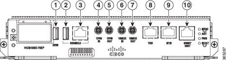
The figure below summarizes the interfaces on the RSP module.
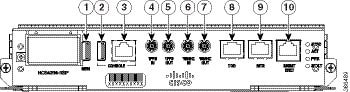
|
Label |
Interface |
|---|---|
|
1 |
USB memory port |
|
2 |
USB console port |
|
3 |
Console port |
|
4 |
1 PPS input timing port |
|
5 |
1 PPS output timing port |
|
6 |
10 MHz input timing port |
|
7 |
10 MHz output timing port |
|
8 |
Time of Day (ToD) timing port |
|
9 |
BITS timing port |
|
10 |
Ethernet management port |
The Cisco NCS420X-RSP module has the following front panel interfaces. For information on cable pinout, see Pinouts.
- 1 USB Type-A Connector for USB-flash (Label = “MEM”)
- 1 USB Type-A Connector for alternate console port (Label = “CONSOLE”)
- RJ45 Connector for Con/Aux (Label = “CONSOLE”)
- RJ48 Jack for BITS interface. (Label = “BITS”)
- RJ48 Jack for Time-of-Day interface. (Label= “TOD”)
- RJ45 Connector for Con/Aux (Label = “MGMT ENET”)
- 4 Mini-Coax connectors (Label = “1PPS IN”, “1PPS OUT”, “10MHZ IN”, “10MHZ OUT”)
For more information about installing the RSP, see RSP Installation. For more information about the RSP LEDs, see RSP LEDs.
Power Supply Features
The Cisco NCS 4206 support DC power supplies. For more information about installing the Cisco NCS 4206 power supplies, see Installing the Power Supply.
To estimate the required power supply, use the Cisco Power Calculator.
The power sections provide more information about the power supply.
Interface Modules
The Cisco NCS 4206 Router interface modules are a field-replaceable unit. In addition to the ports provided on an RSP, the Cisco NCS 4206 Router supports the following interface modules:
8-port 10 Gigabit Ethernet Interface Module (8X10GE)

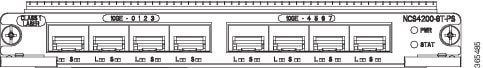
The high density 8x10 Gigabit Ethernet interface module supports eight 10 Gigabit Ethernet ports using SFP+ transceivers cages on the faceplate.
Note |
8x10 Gigabit Ethernet interface module does not support XFP transceivers on the ports. |
For more information about installing a 8X10GE module, see Interface Module Installation.
1-port 100 Gigabit Ethernet Interface Module (1X100GE)
The single port 100 Gigabit Ethernet interface module supports 100 Gigabit Ethernet port.

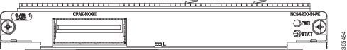
For more information about installing a 1X100GE module, see Interface Module Installation.
2-Port 100 Gigabit Ethernet Interface Module (2X100GE)
The 2-port 100 Gigabit Ethernet Interface Module (NCS4200-2H-PQ) design supports only one 100G QSFP28 optics on Port 0. Port 1 is disabled with RSP3. It currently supports only one mode of operation with 100Gbps of traffic with RSP3.

Limitations of 2X100 GE IM
After any QSFP28 100G optics is inserted, it takes approximately 10 seconds for the optics to be detected and the link to come up. We recommend this time delay for complete initialization and operation.
After inserting the cable or after unshutting the 100G interface, the 100G link may take approximately about 2 seconds to come up.
Note |
QSFP-100G-SR4-S and QSFP-100G-LR4-S are the supported optics for 2X100GE IM for the release 16.10.1. |
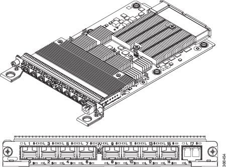
8x1 Gigabit Ethernet SFP + 1x10 Gigabit Ethernet SFP+ Combination Interface Module
The 8-port 1 Gigabit Ethernet SFP interface module with the 1-port 10 Gigabit Ethernet interface module is a high density combination interface module. This module supports 8 Gigabit Ethernet SFP ports and 1 10 Gigabit Ethernet SFP+ port.

For more information about installing the 8X1 GE SFP + 1X10 SFP Gigabit Ethernet module, seeInterface Module Installation.
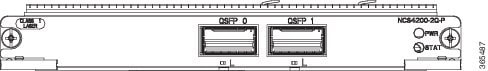
2-port 40 Gigabit Ethernet QSFP Interface Module (2X40GE)
The dual port 40 Gigabit Ethernet interface module supports the 40 Gigabit Ethernet port. The 40G interface is supported using QSFP+ optics.
For more information about installing a 2X40 GE module, see Installing an Interface Module.
1-port OC-192 or 8-port Low Rate CEM Interface Module (10G HO / 10G LO)
The OC-192 interface module with 8-port low rate CEM interface module is a high density combination interface module. This module supports 1-port OC-192 port or 8 low rate CEM or 1 Gigabit Ethernet port.

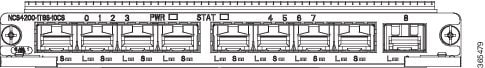
The OC-192 interface modules are supported on slots 2, 3, 4 and 5 on the chassis.
Ports on the OC-192 are numbered from 1 to 8.
- Ports 0 to 7 are multi-rate ports, that support OC-3, OC-12, OC-48, Fast Ethernet interfaces, and the 1 Gigabit Ethernet interfaces.
- Port 8 is the 10 Gigabit Ethernet port that supports the OC-192 interfaces.
Port Restrictions
- The SFP+ port configuration is supported only on OC-192 interfaces port. If this port is enabled, other SFP ports cannot be used (see the table below ).
- Each SFP port can be configured for SONET or Ethernet.
- SFP ports configuration
parameter, (see the table below ):
- Maximum of 4 x OC-48 interfaces are supported per interface module
- For each OC-48 port enabled, neighboring SFP ports cannot be configured
- OC-3 and OC-12 port configuration is supported on all ports simultaneously
- 1 Gigabit Ethernet port configuration is supported on all ports simultaneously
Note |
1 Gigabit Ethernet port configuration is not supported in Cisco IOS XE Release 3.18S. |
- Seamless migration from SONET to 1 Gigabit Ethernet interfaces is supported on all SFP ports.
Port Combinations Usage Guidelines
|
SFP+ Port |
Or |
SFP+ Port |
Or |
SFP+ Port |
Or |
SFP+ Port |
||||||||
|
SFP+ Port 8 |
OC-192 |
SFP+ Port 8 |
— |
SFP+ Port 8 |
— |
SFP+ Port 8 |
— |
|||||||
|
SPF Port |
7 |
— |
SPF Port |
7 |
OC-48 |
SPF Port |
7 |
OC-3 |
SPF Port |
7 |
1 GE |
|||
|
6 |
— |
6 |
— |
6 |
OC-12 |
6 |
1 GE |
|||||||
|
5 |
— |
5 |
OC-48 |
5 |
OC-12 |
5 |
1 GE |
|||||||
|
4 |
— |
4 |
— |
4 |
OC-3 |
4 |
1 GE |
|||||||
|
3 |
— |
3 |
OC-48 |
3 |
OC-3 |
3 |
1 GE |
|||||||
|
2 |
— |
2 |
— |
2 |
OC-12 |
2 |
1 GE |
|||||||
|
1 |
— |
1 |
OC-48 |
1 |
OC-12 |
1 |
1 GE |
|||||||
|
0 |
— |
0 |
— |
0 |
OC-3 |
0 |
1 GE |
For more information about installing the OC-192 interface module, see Interface Module Installation.
NCS 4200 1-Port OC-192 or 8-Port Low Rate CEM 20G Bandwidth Interface Module (NCS4200-1T8S-20CS)
The NCS 4200 1-Port OC-192 or 8-Port Low Rate CEM 20G Bandwidth Interface Module, iMSG is a cost-effective interface module (IM) that supports CEM and Multiservice Gateway features on the OCn interfaces.
Note |
The Multiservice Gateway features are not supported on this IM on Cisco IOS XE Release 16.12.1. |

The NCS 4200 1-Port OC-192 or 8-Port Low Rate CEM 20G Bandwidth Interface Module, iMSG IM supports eight SFP optical interfaces supporting at OC-3/OC-12/OC-48/1G rates and a single SFP+ optical interface supporting at OC-192/10G.
This IM operates in two modes:
-
20G mode; uses two XFI lanes towards the system
-
10G mode; uses single XFI lane towards the system
The benefits of this IM are:
-
Improves backplane efficiency
-
Increases system capacity
-
Increases client flexibility
The most important feature of the NCS 4200 1x10G MR + 8x20G LR CEM, iMSG IM is it provides more flexibility from the interface, which allows you to configure any interface speed on the OCn port irrespective of the IM bandwidth. The bandwidth restriction comes into effect only when the circuit is configured.
For example, you can configure the SFP+ port as an OC-192 and the other eight optical ports as OC-48 to have the total interface speed of 30G. However, if you configure only one STS-1 HO CEP on each port that will take only 9xSTS-1, which is equivalent to 500 Mbps (9 x 52Mbps x1.06) of the backplane traffic.
Restrictions
-
On the port capable of OC-192 speed, lower speed such as, OC-3, OC-12, or OC-48 are not supported.
-
No license is required to enable the Ethernet, OTN and Sonet/SDH functionalities.
-
The SFP port supports OC-3, OC-12, and OC-48. SFP+ port supports OC-192.
Support Information
|
Router |
RSP Module |
Recommended Slots |
Supported Mode |
||
|---|---|---|---|---|---|
|
NCS 4206 |
A900-RSP3-400 |
2, 3, 4, 5 |
10G or 20G |
||
|
NCS 42165 |
A900-RSP3-400 |
3, 7, 11 |
10G or 20G
|
||
|
5, 9, 13, 15 |
10G |
||||
|
NCS 4216 F2B |
A900-RSP3-400 |
0, 1, 2, 5, 6, 9, 10, 13, 14, 15 |
10G |
||
|
A900-RSP3-400 |
3, 4, 7, 8, 11, 12 |
20G |
8/16-Port 1 Gigabit Ethernet (SFP / SFP) + 1-port 10 Gigabit Ethernet (SFP+) / 2-port 1 Gigabit Ethernet (CSFP) Interface Module
-
The 8-port 1 Gigabit Ethernet ports can also be used as 16-port 1 Gigabit Ethernet ports Small Form-Factor Pluggable (SFP) .
-
The 1-port 10 Gigabit Ethernet port can also be used as 2-port 1 Gigabit Ethernet ports with Small Form-Factor Pluggable (SFP+).
-
8 x 1GigE (SFP) Fully subscribed mode (FS)
-
8 x 1GigE (SFP) + 1 x 10GigE (SFP+) Fully subscribed mode (FS)
-
16 x 1GigE (C-SFP) + 1 x 10GigE (SFP+) Fully subscribed mode (FS)
-
16 or 18 x 1GigE (C-SFP) Oversubscribed mode (OS)
-
16 x 1GigE (C-SFP) + 1 x 10GigE (SFP+) Oversubscribed mode (OS)
-
8 or 9 x 1GigE (SFP) Fully subscribed mode (FS)
-
1 x 10GigE (SFP+) Fully subscribed mode (FS)
For more information about installing a 1xSFP or CSFP and 8xSFP or CSFP, see Installing an Interface Module.
For more information on port numbering, see Configuring 8/16-port 1 Gigabit Ethernet (SFP/SFP) + 1-port 10 Gigabit Ethernet (SFP+) / 2-port 1 Gigabit Ethernet (CSFP) Interface Module chapter of the Cisco NCS 4200 Series Software Configuration Guide, Cisco IOS XE Fuji 16.7.x.
1-Port OC48/ STM-16 or 4-port OC-12/OC-3 / STM-1/STM-4 + 12-port T1/E1 + 4-Port T3/E3 CEM Interface Module
-
12xDS1/E1 + 4xDS3/E3/STS-1e interface over the high-density port.
-
1xOC48/12/3 or 1GE interface and 3xOC12/3 or 1GE interface.
Note |
If OC48 is enabled, then the remaining 3 ports are disabled. |

For more information on the supported SFP modules, see the Cisco NCS 4200 Series Network Convergence System Interface Modules Data Sheet.
48-port T1/E1 CEM Interface Module
The 48-port T1/E1 interface module provides connectivity for up to 48-port T1/E1 ports through 3 high-density connectors on the front panel (see the figure below). Each port supports 16 TX and RX ports. For information on LEDs, see Troubleshooting.

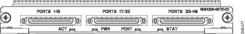
For more information about installing the 48-port T1/E1 interface module, see Interface Module Installation.
48-port T3/E3 CEM Interface Module
The 48-port T3/E3 interface module provides connectivity for up to 48-port T3/E3 ports through 3 high-density connectors on the front panel (see the figure below). Each port supports 16 TX and RX ports. For information on LEDs, see Troubleshooting.

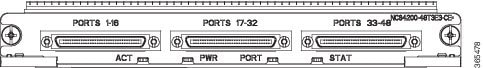
For more information about installing the 48-port T3/E3 interface module, seeInterface Module Installation.
8-port T1/E1 Interface Module (A900-IMA8D)
The 8-port T1/E1 interface module provides connectivity for up to 8 T1/E1 ports through RJ48C port connectors on the front panel. The figure below shows the interface module. For information on supported slots, see Supported RSPs.

Temperature Sensor
The Cisco NCS 4206 has a temperature sensor to detect overtemperature conditions inside the chassis.
Temperature Sensors on the RSP modules
The maximum operating temperature of NCS420X-RSP module and the interface modules is less than the maximum operating temperature of the Cisco NCS 4206.
The IOS XE software decides the appropriate temperature thresholds to generate warnings, and shuts down the system when abnormally high temperature is detected.
Patch Panels
The Cisco router has patch panels modules that provide interconnections with the interface modules.
The following table shows different types of patch panel:
|
Patch Panel |
Description |
|---|---|
|
PANEL-48-1-DIN |
48X75 ohm E1/DS1 termination, through DIN 1.0/2.3 connectors |
|
PANEL-48-1-RJ48 |
48X120 ohm E1/110 ohm DS1 termination, through RJ 48C connector |
|
PANEL-48-1-AMP64 |
48X120 ohm E1/110 ohm DS1 termination, through 4xAMP 64-pin |
|
PANEL-144-1-AMP64 |
144X120 ohm E1/110 ohm DS1 termination, through 12XAMP64-pin |
|
Patch Panel |
Description |
|---|---|
|
PANEL-48-3-DIN |
48X75 ohm E3/DS3 termination, through DIN 1.0/2.3 connectors |
|
PANEL-48-3-HDBNC |
48X75 ohm E3/DS3 termination, through HDBNC connectors |
The 48 X T1/E1 TDM interface modules and 48 X T3/E3 TDM interface modules supports a maximum of 48 TDM ports. These ports are available on the interface modules through three Very-High-Density Cable Interconnect (VHDCI) 16-port connectors. The patch panels listed above make these 48 ports available to the user via different port densities (48- or 144-port patch panels) with standard Telco connectors (DIN, RJ48, and AMP64 for T1/E1 and DIN, HDBNC for T3/E3).


|
Patch Panel |
Description |
|---|---|
|
PANEL-16-DIN |
16X75 ohm E1 termination, through DIN 1.0/2.3 connectors |
The 48 X T1/E1 TDM interface modules and the 48 X T3/E3 TDM interface modules support a maximum of 48 TDM ports. These ports are available on the interface modules through three Very-High-Density Cable Interconnect (VHDCI) 16-port connectors. The patch panels listed above make these 48 ports available to the user via different port densities (48- or 144-port patch panels) with standard Telco connectors (DIN, RJ48, and AMP64 for T1/E1 and DIN, HDBNC for T3/E3).


 Feedback