Overview of PTP Solution

Overview of PTP

Challenges

In today's fast growing network traffic, network operators are adding new nodes to ensure smooth traffic flow in data centers and networks. Addition of new nodes increases the latency of data over the networks. Network latency poses huge challenge for network operators. To avoid delays in synchronizing time signals and latency in the network, the need for precise timing synchronization is on the rise. PTP offers synchronizing timing solution across networks with high precision.

Solution

Cisco has devised the PTP solution over NCS 2000 networks to help you avoid latency and ensure timing synchronization in your networks. NCS 2000 provides the operational capacity to meet your ever-increasing network needs. PTP for the NCS 2000 networks combines the operational functionality of NCS 2000 and precise PTP synchronization to enhance the efficiency of your networks. You can implement this solution over an existing NCS 2000 optical network using NCS 5500 and NCS 540.

The NCS 5500 and NCS 540 routers provide PTP support to the NCS 2000 networks. The solution leverages the PTP signal from NCS 5500 and NCS 540 to provide a path for transparent clock synchronization over the NCS 2000 network.

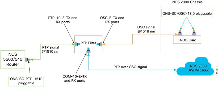
Previously, the NCS 2000 networks used an in-band channel to send PTP signal from NCS 5500 and NCS 540 through the network to synchronize timing reference. PTP signal that is sent over an in-band channel limited users from utilizing the entire NCS 2000 bandwidth. The PTP filter is introduced to propagate the PTP signal through an out-of-band OSC signal at 1518 nm. Keeping all in-band channels available for carrying traffic, this filter enables you to utilize all the channels in the NCS 2000 networks.

In the following example, the Grandmaster (GM) clock feeds the PTP signals to the NCS 5500 router (First Router) through a primary clock (TBC). The ONS-SC-PTP-1510 pluggable that is installed in the NCS 55xx router enables the router to synchronize timing signals over the NCS 2000 DWDM cloud.

Figure 1. PTP Solution for NCS 2000 DWDM Cloud Using NCS 5500 and NCS 540 Routers
This image shows the PTP solution for the NCS 2000 DWDM using NCS 5500 and NCS 540 routers.

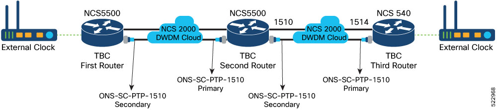
On the NCS 55xx router side, the PTP (optical clock) signal is generated using an external clock that acts as the GM clock. The GM clock synchronizes the PTP signal with Boundary Clocks (BC), both primary and secondary clocks, which are distributed over the network. Primary clocks initiate their own PTP session with downstream secondary clocks to mitigate the number of network hops and packet delays between the GM and secondary clocks. The ONS-SC-PTP-1510 and ONS-SC-PTP-1514 pluggable optics are introduced to support the NCS 55xx routers to propagate the PTP clock signals over the NCS 2000 DWDM cloud.

The PTP solution is implemented using SFP pluggable optics and a PTP filter. The PTP filter combines and splits the PTP and OSC signals in the NCS 2000 network. The pluggable optics are inserted in the NCS 5500 and NCS 540 routers to send the PTP signal. This solution requires the following pluggable optics and filter:

Table 1. Hardware Specifications

Product ID

Description

ONS-SC-PTP-1510

Multirate GE, FE pluggable optics, 1510 nm, C-temp

ONS-SC-PTP-1514

Multirate GE, FE pluggable optics, 1514 nm, C-temp

15216-OSC-PTP

Passive OSC-PTP coupler filter, 1510 nm, 1514 nm, 1518 nm

PTP Filter

PTP filter enables multiplexing and demultiplexing of the OSC and PTP signals over the NCS 2000 networks. The filter is introduced to send the PTP signal over an OOB OSC channel in the NCS 2000 networks. The filter receives the PTP signal from NCS 5500 or 540 and the OSC signal from the NCS 2000 controller cards. It combines both the signals and sends the PTP signal over a line card OSC channel in the NCS 2000 network.

An SFP in the NCS 5500 or 540 router sends the PTP signal at 1510 or 1514 nm to the filter. The controller card sends the OSC signal at 1518 nm to the filter. The filter sends the combined signal through an OSC channel of the NCS 2000 line cards. The filter is connected to the routers and cards on east and west sides for PTP transmission.

PTP Pluggable Optics

PTP pluggable optics enable transmission of the PTP signals to the NCS 2000 DWDM networks. PTP SFPs are hosted on routers such as NCS 540 or NCS 55xx that support sending and receiving PTP signals. The PTP pluggable optics come in two variants, each for 1510 and 1514 nm respectively. Both variants support DWDM transmission at 1 Gbps. The optics are designed as bidirectional to avoid the latency that arises with up and down fibers in full duplex communication.

The ONS-SC-PTP-1510 pluggable sends PTP signal at 1510-nm wavelength and can receive 1514-nm signals from the other end.

The ONS-SC-PTP-1514 pluggable sends PTP signal at 1514-nm wavelength and can receive 1510-nm signals from the other end.


Note

When using these pluggable optics for intralab connectivity, you must add an appropriate attenuator (15 or 20 dB) to the optics in the connection.


Bring Up of PTP Over OSC Link Workflow

The following workflow brings up the PTP over OSC link for the NCS 2000 networks:

  1. Install Cisco ONS 15216 OSC PTP Filter Module on NCS 2000 networks. See Installation section in the Installing the Cisco ONS 15216 DWDM and CWDM Passive Optical Modules book.

  2. Ground PTP module and clean module ports. See Ground Description section in Installing the Cisco ONS 15216 DWDM and CWDM Passive Optical Modules book.

  3. Connect cables. See PTP Module Port Connections.

  4. Configure PTP Clock Signal. See Configuration of PTP Clock Signal.

PTP Module Port Connections

The following image shows the PTP filter port connections with NCS 5500 / NCS 540 and TNCS-2O in NCS 2000.

Figure 2. PTP Filter Port Connections Block Diagram
The image shows the block diagram of PTP filter port connections with NCS 5500 / NCS 540 and NCS 2000 chassis.

The preceding image shows the PTP over OSC signal entering the NCS 2000 DWDM cloud. Many PTP filters are required in the network for free flow of the PTP over OSC signal.

The following table provides the cabling connection between the router and controller card with the PTP filter for both east and west direction.

Table 2. West and East Port Connections of the PTP Filter Module
NCS 5500 / NCS 540 Router Side NCS 2000 Controller Card Side To PTP Filter (West) From PTP Filter (East) NCS 2000 Controller Card Side NCS 5500 / NCS 540 Router Side
Pluggable Optics Controller Card Port (Pluggable) Ports Ports Controller Card Port (Pluggable) Pluggable Optics
TNSC-2O (TX) OTDR/ OSC embedded ports (ONS-SC-OSC-18.0)

OSC-W-RX

Column Left Empty Intentionally

OSC-E-RX

TNSC-2O (TX) OTDR/ OSC embedded ports (ONS-SC-OSC-18.0)
TNSC-2O (RX)

OSC-W-TX

OSC-E-TX

TNSC-2O (RX)

ONS-SC-PTP-1514 (TX)

PTP-14-W-RX

PTP-10-E-RX

ONS-SC-PTP-1510 (TX)

ONS-SC-PTP-1514 (RX)

PTP-14-W-TX

PTP-10-E-TX

ONS-SC-PTP-1510 (RX)

Configuration of PTP Clock Signal

The PTP signal can be configured only on the NCS 5500 and NCS 540 routers. PTP solution examples that are provided in this guide support only the G.8275.1 profile. For more information on the PTP signal configuration, see Configuring Precision Time Protocol.