- Preface
- Product Overview
- Configuring the Router for the First Time
- Configuring a Supervisor Engine 720
- Configuring a Route Switch Processor 720
- Configuring NSF with SSO Supervisor Engine Redundancy
- ISSU and eFSU on Cisco 7600 Series Routers
- Configuring RPR and RPR+ Supervisor Engine Redundancy
- Configuring Interfaces
- Configuring a Supervisor Engine 32
- Configuring LAN Ports for Layer 2 Switching
- Configuring Flex Links
- Configuring EtherChannels
- Configuring VTP
- Configuring VLANs
- Configuring Private VLANs
- Configuring Cisco IP Phone Support
- Configuring IEEE 802.1Q Tunneling
- Configuring Layer 2 Protocol Tunneling
- Configuring L2TPv3
- Configuring STP and MST
- Configuring Optional STP Features
- Configuring Layer 3 Interfaces
- Configuring GTP-SLB IPV6 Support
- IP Subscriber Awareness over Ethernet
- Configuring UDE and UDLR
- Configuring Multiprotocol Label Switching on the PFC
- Configuring IPv4 Multicast VPN Support
- Configuring Multicast VPN Extranet Support
- Configuring IP Unicast Layer 3 Switching
- Configuring IPv6 Multicast PFC3 and DFC3 Layer 3 Switching
- Configuring IPv4 Multicast Layer 3 Switching
- Configuring MLDv2 Snooping for IPv6 Multicast Traffic
- Configuring IGMP Snooping for IPv4 Multicast Traffic
- Configuring PIM Snooping
- Configuring Network Security
- Understanding Cisco IOS ACL Support
- Configuring VRF aware 6RD Tunnels
- Configuring VLAN ACLs
- Private Hosts (Using PACLs)
- Configuring IPv6 PACL
- IPv6 First-Hop Security Features
- Configuring Online Diagnostics
- Configuring Denial of Service Protection
- Configuring DHCP Snooping
- Configuring Dynamic ARP Inspection
- Configuring Traffic Storm Control
- Unknown Unicast Flood Blocking
- Configuring PFC QoS
- Configuring PFC QoS Statistics Data Export
- Configuring MPLS QoS on the PFC
- Configuring LSM MLDP based MVPN Support
- Configuring IEEE 802.1X Port-Based Authentication
- Configuring IEEE 802.1ad
- Configuring Port Security
- Configuring UDLD
- Configuring NetFlow and NDE
- Configuring Local SPAN, RSPAN, and ERSPAN
- Configuring SNMP IfIndex Persistence
- Power Management and Environmental Monitoring
- Configuring Web Cache Services Using WCCP
- Using the Top N Utility
- Using the Layer 2 Traceroute Utility
- Configuring Bidirectional Forwarding and Detection over Switched Virtual Interface
- Configuring Call Home
- Configuring IPv6 Policy Based Routing
- Using the Mini Protocol Analyzer
- Configuring Resilient Ethernet Protocol
- Configuring Synchronous Ethernet
- Configuring Link State Tracking
- Configuring BGP PIC Edge and Core for IP and MPLS
- Configuring VRF aware IPv6 tunnels over IPv4 transport
- ISIS IPv4 Loop Free Alternate Fast Reroute (LFA FRR)
- Multicast Service Reflection
- Y.1731 Performance Monitoring
- Online Diagnostic Tests
- Acronyms
- Cisco IOS Release 15S Software Images
- Index
Cisco 7600 Series Router Software Configuration Guide, Cisco IOS Release 15S
Bias-Free Language
The documentation set for this product strives to use bias-free language. For the purposes of this documentation set, bias-free is defined as language that does not imply discrimination based on age, disability, gender, racial identity, ethnic identity, sexual orientation, socioeconomic status, and intersectionality. Exceptions may be present in the documentation due to language that is hardcoded in the user interfaces of the product software, language used based on RFP documentation, or language that is used by a referenced third-party product. Learn more about how Cisco is using Inclusive Language.
- Updated:
- July 31, 2014
Chapter: Configuring IEEE 802.1Q Tunneling
Configuring IEEE 802.1Q Tunneling
This chapter describes how to configure IEEE 802.1Q tunneling on the Cisco 7600 series routers.

Note • For complete syntax and usage information for the commands used in this chapter, refer to the Cisco 7600 Series Routers Command References at this URL:
http://www.cisco.com/en/US/products/hw/routers/ps368/prod_command_reference_list.html
- The WS-X6548-GE-TX, WS-X6548V-GE-TX, WS-X6148-GE-TX, and WS-X6148V-GE-TX switching modules do not support IEEE 802.1Q tunneling.
Understanding How 802.1Q Tunneling Works
802.1Q tunneling enables service providers to use a single VLAN to support customers who have multiple VLANs, while preserving customer VLAN IDs and keeping traffic in different customer VLANs segregated.
A port configured to support 802.1Q tunneling is called a tunnel port. When you configure tunneling, you assign a tunnel port to a VLAN that you dedicate to tunneling, which then becomes a tunnel VLAN. To keep customer traffic segregated, each customer requires a separate tunnel VLAN, but that one tunnel VLAN supports all of the customer’s VLANs.
802.1Q tunneling is not restricted to point-to-point tunnel configurations. Any tunnel port in a tunnel VLAN is a tunnel entry and exit point. An 802.1Q tunnel can have as many tunnel ports as are needed to connect customer routers.
The customer routers are trunk connected, but with 802.1Q tunneling, the service provider routers only use one service provider VLAN to carry all the customer VLANs, instead of directly carrying all the customer VLANs.
With 802.1Q tunneling, tagged customer traffic comes from an 802.1Q trunk port on a customer device and enters the service-provider edge router through a tunnel port. The link between the 802.1Q trunk port on a customer device and the tunnel port is called an asymmetrical link because one end is configured as an 802.1Q trunk port and the other end is configured as a tunnel port. You assign the tunnel port to an access VLAN ID unique to each customer. See Figure 17-1 and Figure 17-2.
Figure 17-1 IEEE 802.1Q Tunnel Ports in a Service-Provider Network

Figure 17-2 Untagged, 802.1Q-Tagged, and Double-Tagged Ethernet Frames

When a tunnel port receives tagged customer traffic from an 802.1Q trunk port, it does not strip the received 802.1Q tag from the frame header; instead, the tunnel port leaves the 802.1Q tag intact, adds a 2-byte Ethertype field (0x8100) followed by a 2-byte field containing the priority (CoS) and the VLAN. The received customer traffic is then put into the VLAN to which the tunnel port is assigned. This Ethertype 0x8100 traffic, with the received 802.1Q tag intact, is called tunnel traffic.
A VLAN carrying tunnel traffic is an 802.1Q tunnel. The tunnel ports in the VLAN are the tunnel’s ingress and egress points.
The tunnel ports do not have to be on the same network device. The tunnel can cross other network links and other network devices before reaching the egress tunnel port. A tunnel can have as many tunnel ports as required to support the customer devices that need to communicate through the tunnel.
An egress tunnel port strips the 2-byte Ethertype field (0x8100) and the 2-byte length field and transmits the traffic with the 802.1Q tag still intact to an 802.1Q trunk port on a customer device. The 802.1Q trunk port on the customer device strips the 802.1Q tag and puts the traffic into the appropriate customer VLAN.
Note Tunnel traffic carries a second 802.1Q tag only when it is on a trunk link between service-provider network devices, with the outer tag containing the service-provider-assigned VLAN ID and the inner tag containing the customer-assigned VLAN IDs.
802.1Q Tunneling Configuration Guidelines and Restrictions
When configuring 802.1Q tunneling in your network, follow these guidelines and restrictions:
- Use asymmetrical links to put traffic into a tunnel or to remove traffic from a tunnel.
- Configure tunnel ports only to form an asymmetrical link.
- Dedicate one VLAN for each tunnel.
- Assign only tunnel ports to VLANs used for tunneling.
- Trunks require no special configuration to carry tunnel VLANs.
- Tunnel ports are not trunks. Any commands to configure trunking are inactive while the port is configured as a tunnel port.
- Tunnel ports learn customer MAC addresses.
- We recommend that you use ISL trunks to carry tunnel traffic between devices that do not have tunnel ports. Because of the 802.1Q native VLAN feature, using 802.1Q trunks requires that you be very careful when you configure tunneling: a mistake might direct tunnel traffic to a non-tunnel port.
- Ensure that the native VLAN of the 802.1Q trunk port in an asymmetrical link carries no traffic. Because traffic in the native VLAN is untagged, it cannot be tunneled correctly. Alternatively, you can enter the global vlan dot1q tag native command to tag native VLAN egress traffic and drop untagged native VLAN ingress traffic.
- Configure jumbo frame support on tunnel ports:
– See the “Configuring Jumbo Frame Support” section.
– Take note of the modules listed in the “Configuring Jumbo Frame Support” section that do not support jumbo frames.
- Jumbo frames can be tunneled as long as the jumbo frame length combined with the 802.1Q tag does not exceed the maximum frame size.
- Because tunnel traffic has the added ethertype and length field and retains the 802.1Q tag within the router, the following restrictions exist:
– The Layer 3 packet within the Layer 2 frame cannot be identified in tunnel traffic.
– Layer 3 and higher parameters cannot be identified in tunnel traffic (for example, Layer 3 destination and source addresses).
– Because the Layer 3 addresses cannot be identified within the packet, tunnel traffic cannot be routed.
– The router can provide only MAC-layer filtering for tunnel traffic (VLAN IDs and source and destination MAC addresses).
– The router can provide only MAC-layer access control and QoS for tunnel traffic.
– QoS cannot detect the received CoS value in the 802.1Q 2-byte Tag Control Information field.
- On an asymmetrical link, the Cisco Discovery Protocol (CDP) reports a native VLAN mismatch if the VLAN of the tunnel port does not match the native VLAN of the 802.1Q trunk. The 802.1Q tunnel feature does not require that the VLANs match. Ignore the messages if your configuration requires nonmatching VLANs.
- Asymmetrical links do not support the Dynamic Trunking Protocol (DTP) because only one port on the link is a trunk. Configure the 802.1Q trunk port on an asymmetrical link to trunk unconditionally.
- The 802.1Q tunneling feature cannot be configured on ports configured to support private VLANs.
- The following Layer 2 protocols work between devices connected by an asymmetrical link:
– UniDirectional Link Detection (UDLD)
– Port Aggregation Protocol (PAgP)
– Link Aggregation Control Protocol (LACP)
- PortFast BPDU filtering is enabled automatically on tunnel ports.
- CDP is automatically disabled on tunnel ports.
- VLAN Trunk Protocol (VTP) does not work between the following devices:
– Devices connected by an asymmetrical link
– Devices communicating through a tunnel
Note VTP works between tunneled devices if Layer 2 protocol tunneling is enabled. See “Configuring Layer 2 Protocol Tunneling,” for configuration details.
- To configure an EtherChannel as an asymmetrical link, all ports in the EtherChannel must have the same tunneling configuration. Because the Layer 3 packet within the Layer 2 frame cannot be identified, you must configure the EtherChannel to use MAC-address-based frame distribution.
The following configuration guidelines are required for your Layer 2 protocol tunneling configuration:
- On all the service provider edge routers, PortFast BPDU filtering must be enabled on the 802.1Q tunnel ports as follows:
Note PortFast BPDU filtering is enabled automatically on tunnel ports.
- At least one VLAN must be available for Native VLAN tagging ( vlan dot1q tag native option). If you use all the available VLANs and then try to enable the vlan dot1q tag native option, the option will not be enabled.
- On all the service provider core routers, tag native VLAN egress traffic and drop untagged native VLAN ingress traffic by entering the following command:
Note If this option is enabled on one router and disabled on another router, all traffic is dropped; all customer routers must have this option configured the same on each router.
The following configuration guidelines are optional for your Layer 2 protocol tunneling configuration:
Configuring 802.1Q Tunneling
These sections describe 802.1Q tunneling configuration:

Caution Ensure that only the appropriate tunnel ports are in any VLAN used for tunneling and that one VLAN is used for each tunnel. Incorrect assignment of tunnel ports to VLANs can forward traffic inappropriately.
Configuring 802.1Q Tunnel Ports
To configure 802.1Q tunneling on a port, perform this task:
Router(config)# interface type 1 slot/port |
||
Router# show dot1q-tunnel [{interface type interface-number}] |
This example shows how to configure tunneling on port 4/1 and verify the configuration:
Configuring the Router to Tag Native VLAN Traffic
The vlan dot1q tag native command is a global command that configures the router to tag native VLAN traffic, and admit only 802.1Q tagged frames on 802.1Q trunks, dropping any untagged traffic, including untagged traffic in the native VLAN.
Note Staring from Release 15.1(2)S, if the native VLAN tagging is enabled globally using the vlan dot1q tag native command, or locally on the port using the switchport trunk native vlan command, then the UDLD packets are sent with VLAN 1 from L2 ports.
To configure the router to tag traffic in the native VLAN, perform this task:
This example shows how to configure the router to tag native VLAN traffic and verify the configuration:
IEEE 802.1ab LLDP
The following sections describe the IEEE 802.1ab Link Layer Discovery Protocol (LLDP) function.
- Understanding LLDP
- Restrictions
- Default LLDP Configuration
- Configuring LLDP on the Cisco 7600 series router
- Troubleshooting Tips
Understanding LLDP
The Cisco Discovery Protocol (CDP) is a layer 2 device discovery protocol (the data link layer) on all Cisco-manufactured devices (routers, bridges, access servers, and switches). CDP allows network management applications to automatically discover other Cisco devices connected to the network.
For more information on CDP commands, see the Cisco IOS Configuration Fundamentals Command Reference Guide at the following location:
http://www.cisco.com/en/US/docs/ios/12_1/configfun/command/reference/frd3001b.html
CDP is mostly used for topology discovery. A non-Cisco device cannot interact with a Cisco device using CDP. To support non-Cisco devices and to allow interoperability between other devices, the IEEE 802.1AB LLDP is used.
- The protocol allows two systems (running different network layer protocols) to learn about each other.
- LLDP is an optional element of a protocol stack in the 802 LAN station.
- LLDP uses the logical link control (LLC) services to transmit and receive information to and from other LLDP agents. LLC provides a Link Service Access Point(LSAP) for access to LLDP. Each LLDP frame is transmitted as a single MAC Service request. Each incoming LLDP frame is received at the MAC Service Access Point(MSAP) by the LLC entity as a MAC service indication.
Figure 17-3 shows a high-level view of LLDP operating in a network.
Figure 17-3 LLDP Block Diagram
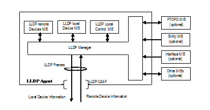
The LLDP protocol operates through the LLDP Agent. The tasks of the LLDP agent are to:
- Collect information from the LLDP local system MIB and transmit it periodically.
- Receive LLDP frames from neighbors and populate LLDP remote devices MIB and other optional MIBs.
LLDP supports a set of attributes used to find the neighbor devices. These attributes are type, length, and value descriptions of devices, and are referred to as Type Length Value (TLV). LLDP supported devices use TLVs to receive and send information to their neighbors. Details such as configuration information, device capabilities, and device identity are also advertised using this protocol.
Restrictions
The following restrictions apply to LLDP:
- The memory available on a given end network device dictates the number of neighbor entries recorded. However, under most operating conditions, end devices such as printers, IP phones, workstations and so on, are typically operated in the receive mode only.
- If objects from the Entity MIB are used for LLDP broadcast, such as to create a sender ID, these MIBs should be available before LLDP can function correctly.
Configuring LLDP on the Cisco 7600 series router
The following sections describe how to configure LLDP on the c7600 platform:
DETAILED STEPS
Configuration Examples
This is an example to enable LLDP globally.
This is an example to specify the delay time in seconds for LLDP to initialize:
This is an example to specify an interval at which the Cisco IOS software sends LLDP updates to the neighboring devices.
This is an example to enable an LLDP TLV on a supported interface:
SUMMARY STEPS
Step 2 show lldp [ entry { * | word } | errors | interface [ ethernet number ] | neighbors [ ethernet number | detail ] | traffic ]
DETAILED STEPS
Verifying the Configuration
This section provides the commands to verify the configuration of LLDP on the Cisco 7600 series router:
 Feedback