- Preface
- Product Overview
- Configuring the Router for the First Time
- Configuring a Supervisor Engine 720
- Configuring a Route Switch Processor 720
- Configuring NSF with SSO Supervisor Engine Redundancy
- ISSU and eFSU on Cisco 7600 Series Routers
- Configuring RPR and RPR+ Supervisor Engine Redundancy
- Configuring Interfaces
- Configuring a Supervisor Engine 32
- Configuring LAN Ports for Layer 2 Switching
- Configuring Flex Links
- Configuring EtherChannels
- Configuring VTP
- Configuring VLANs
- Configuring Private VLANs
- Configuring Cisco IP Phone Support
- Configuring IEEE 802.1Q Tunneling
- Configuring Layer 2 Protocol Tunneling
- Configuring L2TPv3
- Configuring STP and MST
- Configuring Optional STP Features
- Configuring Layer 3 Interfaces
- Configuring GTP-SLB IPV6 Support
- IP Subscriber Awareness over Ethernet
- Configuring UDE and UDLR
- Configuring Multiprotocol Label Switching on the PFC
- Configuring IPv4 Multicast VPN Support
- Configuring Multicast VPN Extranet Support
- Configuring IP Unicast Layer 3 Switching
- Configuring IPv6 Multicast PFC3 and DFC3 Layer 3 Switching
- Configuring IPv4 Multicast Layer 3 Switching
- Configuring MLDv2 Snooping for IPv6 Multicast Traffic
- Configuring IGMP Snooping for IPv4 Multicast Traffic
- Configuring PIM Snooping
- Configuring Network Security
- Understanding Cisco IOS ACL Support
- Configuring VRF aware 6RD Tunnels
- Configuring VLAN ACLs
- Private Hosts (Using PACLs)
- Configuring IPv6 PACL
- IPv6 First-Hop Security Features
- Configuring Online Diagnostics
- Configuring Denial of Service Protection
- Configuring DHCP Snooping
- Configuring Dynamic ARP Inspection
- Configuring Traffic Storm Control
- Unknown Unicast Flood Blocking
- Configuring PFC QoS
- Configuring PFC QoS Statistics Data Export
- Configuring MPLS QoS on the PFC
- Configuring LSM MLDP based MVPN Support
- Configuring IEEE 802.1X Port-Based Authentication
- Configuring IEEE 802.1ad
- Configuring Port Security
- Configuring UDLD
- Configuring NetFlow and NDE
- Configuring Local SPAN, RSPAN, and ERSPAN
- Configuring SNMP IfIndex Persistence
- Power Management and Environmental Monitoring
- Configuring Web Cache Services Using WCCP
- Using the Top N Utility
- Using the Layer 2 Traceroute Utility
- Configuring Bidirectional Forwarding and Detection over Switched Virtual Interface
- Configuring Call Home
- Configuring IPv6 Policy Based Routing
- Using the Mini Protocol Analyzer
- Configuring Resilient Ethernet Protocol
- Configuring Synchronous Ethernet
- Configuring Link State Tracking
- Configuring BGP PIC Edge and Core for IP and MPLS
- Configuring VRF aware IPv6 tunnels over IPv4 transport
- ISIS IPv4 Loop Free Alternate Fast Reroute (LFA FRR)
- Multicast Service Reflection
- Y.1731 Performance Monitoring
- Online Diagnostic Tests
- Acronyms
- Cisco IOS Release 15S Software Images
- Index
- Understanding How Local SPAN, RSPAN, and ERSPAN Work
- Local SPAN, RSPAN, and ERSPAN Configuration Guidelines and Restrictions
- Configuring Local SPAN, RSPAN, and ERSPAN
Configuring Local SPAN, RSPAN, and ERSPAN
This chapter describes how to configure local Switched Port Analyzer (SPAN), remote SPAN (RSPAN), and Encapsulated RSPAN (ERSPAN) on the Cisco 7600 series routers. Policy Feature Card 3 (PFC3) supports ERSPAN (see the “ERSPAN Guidelines and Restrictions” section).

Note ●![]() For complete syntax and usage information for the commands used in this chapter, refer to the Cisco 7600 Series Routers Command References at this URL:
For complete syntax and usage information for the commands used in this chapter, refer to the Cisco 7600 Series Routers Command References at this URL:
http://www.cisco.com/en/US/products/hw/routers/ps368/prod_command_reference_list.html
Understanding How Local SPAN, RSPAN, and ERSPAN Work
These sections describe how local SPAN, RSPAN, and ERSPAN work:
- Local SPAN, RSPAN, and ERSPAN Overview
- Local SPAN, RSPAN, and ERSPAN Sources
- Local SPAN, RSPAN, and ERSPAN Destinations
Local SPAN, RSPAN, and ERSPAN Overview
SPAN copies traffic from one or more ports, one or more EtherChannels, or one or more VLANs, and sends the monitored traffic to one or more destinations such as a SwitchProbe device or other remote monitoring (RMON) probe.
SPAN does not affect the switching of traffic on sources. You must dedicate the destination for SPAN use. The SPAN-generated copies of traffic compete with user traffic for router resources.
These sections provide an overview of local SPAN, RSPAN, and ERSPAN:
Local SPAN Overview
A local SPAN session is an association of source ports and source VLANs with one or more destinations. You configure a local SPAN session on a single router. Local SPAN does not have separate source and destination sessions.
Local SPAN sessions do not copy locally sourced RSPAN VLAN traffic from source trunk ports that carry RSPAN VLANs. Local SPAN sessions do not copy locally sourced RSPAN generic routing encapsulation (GRE)-encapsulated traffic from source ports.
Each local SPAN session can have either ports or VLANs as sources, but not both.
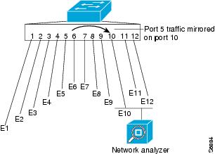
Local SPAN copies traffic from one or more source ports in any VLAN or from one or more VLANs to a destination for analysis (see Figure 57-1). For example, as shown in Figure 57-1, all traffic on Ethernet port 5 (the source port) is copied to Ethernet port 10. A network analyzer on Ethernet port 10 receives all traffic from Ethernet port 5 without being physically attached to Ethernet port 5.
Figure 57-1 Example SPAN Configuration
RSPAN Overview
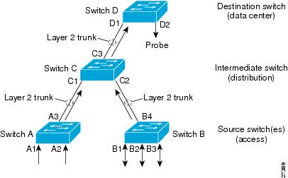
RSPAN supports source ports, source VLANs, and destinations on different routers. This provides remote monitoring of multiple routers across your network (see Figure 57-2). RSPAN uses a Layer 2 VLAN to carry SPAN traffic between routers.
RSPAN consists of an RSPAN source session, an RSPAN VLAN, and an RSPAN destination session. You separately configure RSPAN source sessions and destination sessions on different routers. To configure an RSPAN source session on one router, you associate a set of source ports or VLANs with an RSPAN VLAN. To configure an RSPAN destination session on another router, you associate the destinations with the RSPAN VLAN.
The traffic for each RSPAN session is carried as Layer 2 nonroutable traffic over a user-specified RSPAN VLAN that is dedicated for that RSPAN session in all participating routers. All participating routers must be trunk-connected at Layer 2.
RSPAN source sessions do not copy locally sourced RSPAN VLAN traffic from source trunk ports that carry RSPAN VLANs. RSPAN source sessions do not copy locally sourced RSPAN GRE-encapsulated traffic from source ports.
Each RSPAN source session can have either ports or VLANs as sources, but not both.
The RSPAN source session copies traffic from the source ports or source VLANs and switches the traffic over the RSPAN VLAN to the RSPAN destination session. The RSPAN destination session switches the traffic to the destination ports.
Figure 57-2 RSPAN Configuration
ERSPAN Overview
ERSPAN supports source ports, source VLANs, and destinations on different routers. This provides remote monitoring of multiple routers across your network (see Figure 57-3). ERSPAN uses a GRE tunnel to carry traffic between routers.
ERSPAN consists of an ERSPAN source session, routable ERSPAN GRE-encapsulated traffic, and an ERSPAN destination session. You separately configure ERSPAN source sessions and destination sessions on different routers.
To configure an ERSPAN source session on one router, you associate a set of source ports or VLANs with a destination IP address, ERSPAN ID number, and optionally with a VPN routing and forwarding (VRF) name. To configure an ERSPAN destination session on another router, you associate the destination ports with the source IP address, ERSPAN ID number, and optionally with a VRF name.
ERSPAN source sessions do not copy locally sourced RSPAN VLAN traffic from source trunk ports that carry RSPAN VLANs. ERSPAN source sessions do not copy locally sourced ERSPAN GRE-encapsulated traffic from source ports.
Each ERSPAN source session can have either ports or VLANs as sources, but not both.
The ERSPAN source session copies traffic from the source ports or source VLANs and forwards the traffic using routable GRE-encapsulated packets to the ERSPAN destination session. The ERSPAN destination session switches the traffic to the destinations.
Figure 57-3 ERSPAN Configuration

Understanding the Traffic Monitored at SPAN Sources
These sections describe the traffic that local SPAN, RSPAN, and ERSPAN sources can monitor:
Monitored Traffic Direction
You can configure local SPAN sessions, RSPAN source sessions, and ERSPAN source sessions to monitor ingress traffic (called ingress SPAN), or to monitor egress traffic (called egress SPAN), or to monitor traffic flowing in both directions.
Ingress SPAN copies traffic received by the source ports and VLANs for analysis at the destination port. Egress SPAN copies traffic transmitted from the source ports and VLANs. When you enter the both keyword, SPAN copies the traffic received and transmitted by the source ports and VLANs to the destination port.
Monitored Traffic Type
By default, local SPAN and ERSPAN monitor all traffic, including multicast and bridge protocol data unit (BPDU) frames. RSPAN does not support BPDU monitoring.
Duplicate Traffic
In some configurations, SPAN sends multiple copies of the same source traffic to the destination. For example, in a configuration with a bidirectional SPAN session (both ingress and egress) for two SPAN sources, called s1 and s2, to a SPAN destination, called d1, if a packet enters the router through s1 and is sent for egress from the switch to s2, ingress SPAN at s1 sends a copy of the packet to SPAN destination d1 and egress SPAN at s2 sends a copy of the packet to SPAN destination d1. If the packet was Layer 2 switched from s1 to s2, both SPAN packets would be the same. If the packet was Layer 3 switched from s1 to s2, the Layer 3 rewrite would alter the source and destination Layer 2 addresses, in which case the SPAN packets would be different.
Local SPAN, RSPAN, and ERSPAN Sources
These sections describe local SPAN, RSPAN, and ERSPAN sources:
Source Ports and EtherChannels
A source port or EtherChannel is a port or EtherChannel monitored for traffic analysis. You can configure both Layer 2 and Layer 3 ports as SPAN sources. SPAN can monitor one or more source ports or EtherChannels in a single SPAN session. You can configure ports or EtherChannels in any VLAN as SPAN sources. Trunk ports or EtherChannels can be configured as sources and mixed with nontrunk sources. SPAN does not copy the encapsulation from a source trunk port.
Source VLANs
A source VLAN is a VLAN monitored for traffic analysis. VLAN-based SPAN (VSPAN) uses a VLAN as the SPAN source. All the ports and EtherChannels in the source VLANs become sources of SPAN traffic.
Note![]() Layer 3 VLAN interfaces on source VLANs are not sources of SPAN traffic. Traffic that enters a VLAN through a Layer 3 VLAN interface is monitored when it is transmitted from the router through an egress port of EtherChannel that is in the source VLAN.
Layer 3 VLAN interfaces on source VLANs are not sources of SPAN traffic. Traffic that enters a VLAN through a Layer 3 VLAN interface is monitored when it is transmitted from the router through an egress port of EtherChannel that is in the source VLAN.
Local SPAN, RSPAN, and ERSPAN Destinations
A SPAN destination is a Layer 2 or Layer 3 LAN port or, with Release 12.2(33)SRC and later, an Etherchannel, to which local SPAN, RSPAN, or ERSPAN sends traffic for analysis. When you configure a port or EtherChannel as a SPAN destination, it is dedicated for use only by the SPAN feature.
Destination EtherChannels do not support the Port Aggregation Protocol (PAgP) or Link Aggregation Control Protocol (LACP) EtherChannel protocols; only the on mode is supported, with all EtherChannel protocol support disabled.
There is no requirement that the member links of a destination EtherChannel be connected to a device that supports EtherChannels. For example, you can connect the member links to separate network analyzers. See Chapter 12, “Configuring EtherChannels” for more information about EtherChannels.
Destinations, by default, cannot receive any traffic. With Release 12.2(33)SRC and later, you can configure Layer 2 destinations to receive traffic from any attached devices.
Destinations, by default, do not transmit anything except SPAN traffic. Layer 2 destinations that you have configured to receive traffic can be configured to learn the Layer 2 address of any devices attached to the destination and transmit traffic that is addressed to the devices.
You can configure trunk ports as destinations, which allows trunk destinations to transmit encapsulated traffic. You can use allowed VLAN lists to configure destination trunk VLAN filtering.
Local SPAN, RSPAN, and ERSPAN Configuration Guidelines and Restrictions
These sections describe local SPAN, RSPAN, and ERSPAN configuration guidelines and restrictions:
- Feature Incompatibilities
- Local SPAN, RSPAN, and ERSPAN Session Limits
- Local SPAN, RSPAN, and ERSPAN Guidelines and Restrictions
- VSPAN Guidelines and Restrictions
- RSPAN Guidelines and Restrictions
- ERSPAN Guidelines and Restrictions
Feature Incompatibilities
These feature incompatibilities exist with local SPAN, RSPAN, and ERSPAN:
- Unknown Unicast Flood Blocking (UUFB) ports cannot be RSPAN or Local SPAN egress-only destinations. (CSCsj27695)
- EoMPLS ports cannot be SPAN sources. (CSCed51245)
- A port-channel interface (an EtherChannel) can be a SPAN source, but you cannot configure active member ports of an EtherChannel as SPAN source ports. Inactive member ports of an EtherChannel can be configured as SPAN sources, but they are put into the suspended state and carry no traffic.
- You cannot configure active member ports of an EtherChannel as SPAN destination ports. Inactive member ports of an EtherChannel can be configured as SPAN destination ports but they are put into the suspended state and carry no traffic.
- These features are incompatible with SPAN destination ports:
–![]() IEEE 802.1X port-based authentication
IEEE 802.1X port-based authentication
–![]() Spanning Tree Protocol (STP) and related features (PortFast, PortFast BPDU Filtering, BPDU Guard, UplinkFast, BackboneFast, EtherChannel Guard, Root Guard, Loop Guard)
Spanning Tree Protocol (STP) and related features (PortFast, PortFast BPDU Filtering, BPDU Guard, UplinkFast, BackboneFast, EtherChannel Guard, Root Guard, Loop Guard)
–![]() VLAN Trunking Protocol (VTP)
VLAN Trunking Protocol (VTP)
–![]() Dynamic Trunking Protocol (DTP)
Dynamic Trunking Protocol (DTP)
Note![]() SPAN destination ports can participate in IEEE 802.3Z Flow Control.
SPAN destination ports can participate in IEEE 802.3Z Flow Control.
Local SPAN, RSPAN, and ERSPAN Session Limits
For Release 12.2(33)SRC and later, Table 57-1 shows the PFC3 local SPAN, RSPAN, and ERSPAN session limits. Table 57-2 shows the PFC3 local SPAN, RSPAN, and ERSPAN source and destination limits.
Local SPAN, RSPAN, and ERSPAN Guidelines and Restrictions
These guidelines and restrictions apply to local SPAN, RSPAN, and ERSPAN:
- ERSPAN destination IP address should be used for the sole purpose of terminating ERSPAN traffic.
- A SPAN destination that is copying traffic from a single egress SPAN source port sends only egress traffic to the network analyzer. However, if you configure more than one egress SPAN source port, the traffic that is sent to the network analyzer also includes these types of ingress traffic that were received from the egress SPAN source ports:
–![]() Any unicast traffic that is flooded on the VLAN
Any unicast traffic that is flooded on the VLAN
–![]() Broadcast and multicast traffic
Broadcast and multicast traffic
This situation occurs because an egress SPAN source port receives these types of traffic from the VLAN but then recognizes itself as the source of the traffic and drops it instead of sending it back to the source from which it was received. Before the traffic is dropped, SPAN copies the traffic and sends it to the SPAN destination. (CSCds22021)
- Entering additional monitor session commands does not clear previously configured SPAN parameters. You must enter the no monitor session command to clear configured SPAN parameters.
- Connect a network analyzer to the SPAN destination.
- Within a SPAN session, all of the SPAN destinations receive all of the traffic from all of the SPAN sources, except when source-VLAN filtering is configured on the SPAN source.
- You can configure destination trunk VLAN filtering to select which traffic is transmitted from the SPAN destination.
- MPA/SPAN replicate traffic immediately when source interface is specified, without waiting for issue of start or no shutdown command.
- When you specify a single VLAN as MPA/SPAN source, all traffic from the physical interface to which that VLAN belongs is forwarded to the supervisor. This may cause over-subscription. MPA/SPAN must be done with caution in centralized mode.
- You can configure both Layer 2 LAN ports (LAN ports configured with the switchport command) and Layer 3 LAN ports (LAN ports not configured with the switchport command) as sources or destinations.
- You cannot mix individual source ports and source VLANs within a single session.
- If you specify multiple ingress source ports, the ports can belong to different VLANs.
- Within a session, you cannot configure both VLANs as SPAN sources and do source VLAN filtering. You can configure VLANs as SPAN sources or you can do source VLAN filtering of traffic from source ports and EtherChannels, but not both in the same session.
- You cannot configure source VLAN filtering for internal VLANs.
- When enabled, local SPAN, RSPAN, and ERSPAN use any previously entered configuration.
- When you specify sources and do not specify a traffic direction (ingress, egress, or both), “both” is used by default.
- SPAN copies Layer 2 Ethernet frames, but SPAN does not copy source trunk port Inter-Switch Link Protocol (ISL) or 802.1Q tags. You can configure destinations as trunks to send locally tagged traffic to the traffic analyzer.
Note![]() A destination configured as a trunk tags traffic from a Layer 3 LAN source port with the internal VLAN used by the Layer 3 LAN port.
A destination configured as a trunk tags traffic from a Layer 3 LAN source port with the internal VLAN used by the Layer 3 LAN port.
- Local SPAN sessions, RSPAN source sessions, and ERSPAN source sessions do not copy locally sourced RSPAN VLAN traffic from source trunk ports that carry RSPAN VLANs.
- Local SPAN sessions, RSPAN source sessions, and ERSPAN source sessions do not copy locally sourced ERSPAN GRE-encapsulated traffic from source ports.
- A port or EtherChannel can be a SPAN destination for only one SPAN session. SPAN sessions cannot share destinations.
- SPAN destinations cannot be SPAN sources.
- Sub-interfaces cannot be added as source interface in SPAN sessions.
- SPAN of an interface with various sub-interfaces configured is not supported.
- Destination ports never participate in any spanning tree instance. Local SPAN includes BPDUs in the monitored traffic, so any BPDUs seen on the destination are from the source. RSPAN does not support BPDU monitoring.
- All packets sent through the router for transmission from a port configured as an egress source are copied to the destination, including packets that do not exit the router through the egress port. This is because STP has put the egress port into the blocking state or, on an egress trunk port because STP has put the VLAN into the blocking state on the trunk port.
VSPAN Guidelines and Restrictions
Note![]() Local SPAN, RSPAN, and ERSPAN all support VSPAN.
Local SPAN, RSPAN, and ERSPAN all support VSPAN.
These are VSPAN guidelines and restrictions:
- VSPAN sessions do not support VLAN filtering.
- For VSPAN sessions with both ingress and egress configured, two packets are forwarded from the destination to the analyzer if the packets get switched on the same VLAN (one as ingress traffic from the ingress port and one as egress traffic from the egress port).
- VSPAN only monitors traffic that leaves or enters Layer 2 ports in the VLAN.
–![]() If you configure a VLAN as an ingress source and traffic gets routed into the monitored VLAN, the routed traffic is not monitored because it never appears as ingress traffic entering a Layer 2 port in the VLAN.
If you configure a VLAN as an ingress source and traffic gets routed into the monitored VLAN, the routed traffic is not monitored because it never appears as ingress traffic entering a Layer 2 port in the VLAN.
–![]() If you configure a VLAN as an egress source and traffic gets routed out of the monitored VLAN, the routed traffic is not monitored because it never appears as egress traffic leaving a Layer 2 port in the VLAN.
If you configure a VLAN as an egress source and traffic gets routed out of the monitored VLAN, the routed traffic is not monitored because it never appears as egress traffic leaving a Layer 2 port in the VLAN.
RSPAN Guidelines and Restrictions
These are RSPAN guidelines and restrictions:
- All participating routers must be connected by Layer 2 trunks.
- Any network device that supports RSPAN VLANs can be an RSPAN intermediate device.
- Networks impose no limit on the number of RSPAN VLANs that the networks carry.
- Intermediate network devices might impose limits on the number of RSPAN VLANs that they can support.
- You must configure the RSPAN VLANs in all source, intermediate, and destination network devices. If enabled, the VTP can propagate configuration of VLANs numbered 1 through 1024 as RSPAN VLANs. You must manually configure VLANs numbered higher than 1024 as RSPAN VLANs on all source, intermediate, and destination network devices.
- If you enable VTP and VTP pruning, RSPAN traffic is pruned in the trunks to prevent the unwanted flooding of RSPAN traffic across the network.
- RSPAN VLANs can be used only for RSPAN traffic.
- Do not configure a VLAN used to carry management traffic as an RSPAN VLAN.
- Do not assign access ports to RSPAN VLANs. RSPAN puts access ports in an RSPAN VLAN into the suspended state.
- Do not configure any ports in an RSPAN VLAN except trunk ports selected to carry RSPAN traffic.
- MAC address learning is disabled in the RSPAN VLAN.
- You can use output access control lists (ACLs) on the RSPAN VLAN in the RSPAN source router to filter the traffic sent to an RSPAN destination.
- RSPAN does not support BPDU monitoring.
- Do not configure RSPAN VLANs as sources in VSPAN sessions.
- You can configure any VLAN as an RSPAN VLAN as long as all participating network devices support configuration of RSPAN VLANs and you use the same RSPAN VLAN for each RSPAN session in all participating network devices.
ERSPAN Guidelines and Restrictions
These are ERSPAN guidelines and restrictions:
- ERSPAN is supported on the PFC3B, PFC3BXL, PFC3C, and PFC3CXL.
- A WS-SUP720 (a Supervisor Engine 720 manufactured with a PFC3A), can only support ERSPAN if it has hardware version 3.2 or later. Enter the show module version | include WS-SUP720-BASE command to display the hardware version. For example:
- For ERSPAN packets, the “protocol type” field value in the GRE header is 0x88BE.
- The payload of a Layer 3 ERSPAN packet is a copied Layer 2 Ethernet frame, excluding any ISL or 802.1Q tags.
- ERSPAN adds a 50-byte header to each copied Layer 2 Ethernet frame and replaces the 4-byte cyclic redundancy check (CRC) trailer.
- ERSPAN supports jumbo frames that contain Layer 3 packets of up to 9,202 bytes. If the length of the copied Layer 2 Ethernet frame is greater than 9,170 (9,152-byte Layer 3 packet), ERSPAN truncates the copied Layer 2 Ethernet frame to create a 9,202-byte ERSPAN Layer 3 packet.
- Regardless of any configured MTU size, ERSPAN creates Layer 3 packets that can be as long as 9,202 bytes. ERSPAN traffic might be dropped by any interface in the network that enforces an MTU size smaller than 9,202 bytes.
- With the default MTU size (1,500 bytes), if the length of the copied Layer 2 Ethernet frame is greater than 1,468 bytes (1,450-byte Layer 3 packet), the ERSPAN traffic is dropped by any interface in the network that enforces the 1,500-byte MTU size.
Note![]() The mtu interface command and the system jumbomtu command (see the “Configuring Jumbo Frame Support” section) set the maximum Layer 3 packet size (default is 1,500 bytes, maximum is 9,216 bytes).
The mtu interface command and the system jumbomtu command (see the “Configuring Jumbo Frame Support” section) set the maximum Layer 3 packet size (default is 1,500 bytes, maximum is 9,216 bytes).
- All participating routers must be connected at Layer 3 and the network path must support the size of the ERSPAN traffic.
- ERSPAN does not support packet fragmentation. The “do not fragment” bit is set in the IP header of ERSPAN packets. ERSPAN destination sessions cannot reassemble fragmented ERSPAN packets.
- ERSPAN traffic is subject to the traffic load conditions of the network. You can set the ERSPAN packet IP precedence or Differentiated Services Code Point (DSCP) value to prioritize ERSPAN traffic for Quality of Service (QoS).
- The only supported destination for ERSPAN traffic is an ERSPAN destination session on a PFC3.
- All ERSPAN source sessions on a router must use the same origin IP address, configured with the origin ip address command (see the “Configuring ERSPAN Source Sessions” section).
- All ERSPAN destination sessions on a switch must use the same IP address on the same destination interface. You enter the destination interface IP address with the ip address command (see the “Configuring ERSPAN Destination Sessions” section).
- The ERSPAN source session’s destination IP address, which must be configured on an interface on the destination router, is the source of traffic that an ERSPAN destination session sends to the destinations. You configure the same address in both the source and destination sessions with the ip address command.
- The ERSPAN ID differentiates the ERSPAN traffic arriving at the same destination IP address from various different ERSPAN source sessions.
- ERSPAN egress is not supported on EVC ports.
Configuring Local SPAN, RSPAN, and ERSPAN
These sections describe how to configure local SPAN, RSPAN, and ERSPAN:
- Configuring a Destination as an Unconditional Trunk (Optional)
- Configuring Destination Trunk VLAN Filtering (Optional)
- Configuring Destination Port Permit Lists (Optional)
- Configuring Local SPAN
- Configuring RSPAN
- Configuring ERSPAN
- Configuring ERSPAN
- Configuring Source VLAN Filtering for Local SPAN and RSPAN
- Verifying the Configuration
- Configuration Examples
Configuring a Destination as an Unconditional Trunk (Optional)
To tag the monitored traffic as it leaves a destination, configure the destination as a trunk before you configure it as a destination.
To configure the destination as a trunk, perform this task in interface configuration mode:
This example shows how to configure a port as an unconditional IEEE 802.1Q trunk:
Note![]() Releases earlier than Release 12.2(33)SRC required you to enter the switchport nonegotiate command when you configured a destination port as an unconditional trunk. This requirement has been removed in Release 12.2(33)SRC and later.
Releases earlier than Release 12.2(33)SRC required you to enter the switchport nonegotiate command when you configured a destination port as an unconditional trunk. This requirement has been removed in Release 12.2(33)SRC and later.
Configuring Destination Trunk VLAN Filtering (Optional)
Note![]() In addition to filtering VLANs on a trunk, you can also apply the allowed VLAN list to access ports.
In addition to filtering VLANs on a trunk, you can also apply the allowed VLAN list to access ports.
Destination trunk VLAN filtering is applied at the destination. Destination trunk VLAN filtering does not reduce the amount of traffic being sent from the SPAN sources to the SPAN destinations.
When a destination is a trunk, you can use the list of VLANs allowed on the trunk to filter the traffic transmitted from the destination. (CSCeb01318)
Destination trunk VLAN filtering removes the restriction that, within a SPAN session, all destinations receive all the traffic from all the sources. Destination trunk VLAN filtering allows you to select, on a per-VLAN basis, the traffic that is transmitted from each destination trunk to the network analyzer.
To configure destination trunk VLAN filtering on a destination trunk, perform this task:
When configuring the list of VLANs allowed on a destination trunk port, note the following information:
- The vlan parameter is either a single VLAN number from 1 through 4094, or a range of VLANs described by two VLAN numbers, the lesser one first, separated by a dash. Do not enter any spaces between comma-separated vlan parameters or in dash-specified ranges.
- All VLANs are allowed by default.
- To remove all VLANs from the allowed list, enter the switchport trunk allowed vlan none command.
- To add VLANs to the allowed list, enter the switchport trunk allowed vlan add command.
- You can modify the allowed VLAN list without removing the SPAN configuration.
This example shows the configuration of a local SPAN session that has several VLANs as sources and several trunk ports as destinations, with destination trunk port VLAN filtering that filters the SPAN traffic so that each destination trunk port transmits the traffic from one VLAN:
Configuring Destination Port Permit Lists (Optional)
To prevent accidental configuration of ports as destinations, you can create a permit list of the ports that are valid for use as destinations. With a destination port permit list configured, you can only configure the ports in the permit list as destinations.
To configure a destination port permit list, perform this task:
This example shows how to configure a destination port permit list that includes Gigabit Ethernet ports 5/1 through 5/4 and 6/1:
This example shows how to verify the configuration:
Configuring Local SPAN
These sections describe how to configure local SPAN sessions:
Configuring Local SPAN (SPAN Configuration Mode)
Note![]() To tag the monitored traffic as it leaves a destination, you must configure the destination to trunk unconditionally before you configure it as a destination (see the “Configuring a Destination as an Unconditional Trunk (Optional)” section).
To tag the monitored traffic as it leaves a destination, you must configure the destination to trunk unconditionally before you configure it as a destination (see the “Configuring a Destination as an Unconditional Trunk (Optional)” section).
To configure a local SPAN session in SPAN configuration mode, perform this task:
When configuring monitor sessions, note the following information:
- session_description can be up to 240 characters and cannot contain special characters; with Release 12.2(33)SRC and later, the description can contain spaces.
Note![]() You can enter 240 characters after the description command.
You can enter 240 characters after the description command.
–![]() interface type slot/port ; type is fastethernet, gigabitethernet, or tengigabitethernet.
interface type slot/port ; type is fastethernet, gigabitethernet, or tengigabitethernet.
–![]() interface port-channel number
interface port-channel number
Note Destination port channel interfaces must be configured with the channel-group group_num mode on command and the no channel-protocol command. See the “Configuring EtherChannels” section.
Note![]() In lists, you must enter a space before and after the comma. In ranges, you must enter a space before and after the dash.
In lists, you must enter a space before and after the comma. In ranges, you must enter a space before and after the dash.
- interface_range is interface type slot/first_port - last_port.
- mixed_interface_list is, in any order, single_interface, interface_range,...
- single_vlan is the ID number of a single VLAN.
- vlan_list is single_vlan, single_vlan, single_vlan...
- vlan_range is first_vlan_ID - last_vlan_ID.
- mixed_vlan_list is, in any order, single_vlan, vlan_range,...
- Enter the ingress keyword to configure destinations to receive traffic from attached devices.
- Enter the learning keyword to enable MAC address learning from the destinations, which allows the switch to transmit traffic that is addresses to devices attached to the destinations.
When configuring destinations with the ingress and learning keywords, note the following:
–![]() Configure the destinations for Layer 2 switching. See the “Configuring LAN Interfaces for Layer 2 Switching” section.
Configure the destinations for Layer 2 switching. See the “Configuring LAN Interfaces for Layer 2 Switching” section.
–![]() If the destination is a trunk and the attached device transmits tagged traffic back to the router, you can use either ISL or 802.1Q trunking.
If the destination is a trunk and the attached device transmits tagged traffic back to the router, you can use either ISL or 802.1Q trunking.
–![]() If the destination is a trunk and the attached device transmits untagged traffic back to the router, use 802.1Q trunking with the native VLAN configured to accept the traffic from the attached device.
If the destination is a trunk and the attached device transmits untagged traffic back to the router, use 802.1Q trunking with the native VLAN configured to accept the traffic from the attached device.
–![]() Do not configure the destination with Layer 3 addresses. Use a VLAN interface to route traffic to and from devices attached to destinations.
Do not configure the destination with Layer 3 addresses. Use a VLAN interface to route traffic to and from devices attached to destinations.
–![]() Destinations are held in the down state. To route the traffic to and from attached devices, configure an additional active Layer 2 port in the VLAN to keep the VLAN interface up.
Destinations are held in the down state. To route the traffic to and from attached devices, configure an additional active Layer 2 port in the VLAN to keep the VLAN interface up.
Note![]() On ES+ line cards, if local SPAN destination is configured with ingress and learning mode the replicated traffic is not egressing on the SPAN. Effective with Cisco IOS 15.2(4) release, even if you configure the local destination with ingress and learning mode the replicated traffic will egress on the SPAN destination.
On ES+ line cards, if local SPAN destination is configured with ingress and learning mode the replicated traffic is not egressing on the SPAN. Effective with Cisco IOS 15.2(4) release, even if you configure the local destination with ingress and learning mode the replicated traffic will egress on the SPAN destination.
This example shows how to configure session 1 to monitor ingress traffic from Gigabit Ethernet port 1/1 and configure Gigabit Ethernet port 1/2 as the destination:
For additional examples, see the “Configuration Examples” section.
Configuring Local SPAN (Global Configuration Mode)
Note![]() To tag the monitored traffic as it leaves a destination, you must configure the destination to trunk unconditionally before you configure it as a destination (see the “Configuring a Destination as an Unconditional Trunk (Optional)” section).
To tag the monitored traffic as it leaves a destination, you must configure the destination to trunk unconditionally before you configure it as a destination (see the “Configuring a Destination as an Unconditional Trunk (Optional)” section).
You can configure up to two local SPAN sessions in global configuration mode.
You can use SPAN configuration mode for all SPAN configuration tasks.
You must use SPAN configuration mode to configure the supported maximum number of SPAN sessions.
Local SPAN does not use separate source and destination sessions. To configure a local SPAN session, configure local SPAN sources and destinations with the same session number. To configure a local SPAN session, perform this task:
When configuring local SPAN sessions, note the following information:
–![]() interface type slot / port ; type is fastethernet, gigabitethernet, or tengigabitethernet.
interface type slot / port ; type is fastethernet, gigabitethernet, or tengigabitethernet.
–![]() interface port-channel number
interface port-channel number
Note Destination port channel interfaces must be configured with the channel-group group_num mode on command and the no channel-protocol command. See the “Configuring EtherChannels” section.
Note![]() In lists, you must enter a space before and after the comma. In ranges, you must enter a space before and after the dash.
In lists, you must enter a space before and after the comma. In ranges, you must enter a space before and after the dash.
- interface_range is interface type slot / first_port - last_port.
- mixed_interface_list is, in any order, single_interface, interface_range,...
- single_vlan is the ID number of a single VLAN.
- vlan_list is single_vlan, single_vlan, single_vlan...
- vlan_range is first_vlan_ID - last_vlan_ID.
- mixed_vlan_list is, in any order, single_vlan, vlan_range,...
- Enter the ingress keyword to configure destinations to receive traffic from attached services.
- Enter the learning keyword to enable MAC address learning from the destinations, which allows the router to transmit traffic that is addressed to devices attached to the destinations.
When configuring destinations with the ingress and learning keywords, note the following:
–![]() Configure the destinations for Layer 2 switching. See the “Configuring LAN Interfaces for Layer 2 Switching” section on page 8-6.
Configure the destinations for Layer 2 switching. See the “Configuring LAN Interfaces for Layer 2 Switching” section on page 8-6.
–![]() If the destination is a trunk and the attached device transmits tagged traffic back to the router, you can use either ISL or 802.1Q trunking.
If the destination is a trunk and the attached device transmits tagged traffic back to the router, you can use either ISL or 802.1Q trunking.
–![]() If the destination is a trunk and the attached device transmits untagged traffic back to the router, use 802.1Q trunking with the native VLAN configured to accept the traffic from the attached device.
If the destination is a trunk and the attached device transmits untagged traffic back to the router, use 802.1Q trunking with the native VLAN configured to accept the traffic from the attached device.
–![]() Do not configure the destination with Layer 3 addresses. Use a VLAN interface to route traffic to and from devices attached to destinations.
Do not configure the destination with Layer 3 addresses. Use a VLAN interface to route traffic to and from devices attached to destinations.
–![]() Destinations are held in the down state. To route the traffic to and from attached devices, configure an additional active Layer 2 port in the VLAN to keep the VLAN interface up.
Destinations are held in the down state. To route the traffic to and from attached devices, configure an additional active Layer 2 port in the VLAN to keep the VLAN interface up.
This example shows how to configure Fast Ethernet port 5/1 as a bidirectional source for session 1:
This example shows how to configure Fast Ethernet port 5/48 as the destination for SPAN session 1:
For additional examples, see the “Configuration Examples” section.
Configuring RSPAN
RSPAN uses a source session on one router and a destination session on a different router. These sections describe how to configure RSPAN sessions:
Configuring RSPAN VLANs
To configure a VLAN as an RSPAN VLAN, perform this task:
Configuring RSPAN Sessions (SPAN Configuration Mode)
These sections describe how to configure RSPAN sessions in SPAN configuration mode:
Configuring RSPAN Source Sessions in SPAN Configuration Mode
To configure an RSPAN source session in SPAN configuration mode, perform this task:
When configuring RSPAN source sessions, note the following information:
- session_description can be up to 240 characters and cannot contain special characters; with Release 12.2(33)SRC and later, the description can contain spaces.
Note![]() You can enter 240 characters after the description command.
You can enter 240 characters after the description command.
–![]() interface type slot / port ; type is fastethernet, gigabitethernet, or tengigabitethernet.
interface type slot / port ; type is fastethernet, gigabitethernet, or tengigabitethernet.
–![]() interface port_channel number
interface port_channel number
Note![]() In lists, you must enter a space before and after the comma. In ranges, you must enter a space before and after the dash.
In lists, you must enter a space before and after the comma. In ranges, you must enter a space before and after the dash.
- interface_range is interface type slot / first_port - last_port.
- mixed_interface_list is, in any order, single_interface, interface_range,...
- single_vlan is the ID number of a single VLAN.
- vlan_list is single_vlan, single_vlan, single_vlan...
- vlan_range is first_vlan_ID - last_vlan_ID.
- mixed_vlan_list is, in any order, single_vlan, vlan_range,...
- See the “Configuring RSPAN VLANs” section for information about the RSPAN VLAN ID.
This example shows how to configure session 1 to monitor bidirectional traffic from Gigabit Ethernet port 1/1:
For additional examples, see the “Configuration Examples” section.
Configuring RSPAN Destination Sessions in SPAN Configuration Mode
Note![]() To tag the monitored traffic, you must configure the port to trunk unconditionally before you configure it as a destination (see the “Configuring a Destination as an Unconditional Trunk (Optional)” section).
To tag the monitored traffic, you must configure the port to trunk unconditionally before you configure it as a destination (see the “Configuring a Destination as an Unconditional Trunk (Optional)” section).
You can configure an RSPAN destination session on the RSPAN source session router to monitor RSPAN traffic locally.
To configure an RSPAN destination session, perform this task:
When configuring RSPAN destination sessions, note the following information:
–![]() interface type slot / port ; type is fastethernet, gigabitethernet, or tengigabitethernet.
interface type slot / port ; type is fastethernet, gigabitethernet, or tengigabitethernet.
–![]() interface port-channel number
interface port-channel number
Note Destination port channel interfaces must be configured with the channel-group group_num mode on command and the no channel-protocol command. See the “Configuring EtherChannels” section.
Note![]() In lists, you must enter a space before and after the comma. In ranges, you must enter a space before and after the dash.
In lists, you must enter a space before and after the comma. In ranges, you must enter a space before and after the dash.
- interface_range is interface type slot / first_port - last_port.
- mixed_interface_list is, in any order, single_interface , interface_range ,...
- Enter the ingress keyword to configure destinations to receive traffic from attached devices.
- Enter the learning keyword to enable MAC address learning from the destinations, which allows the switch to transmit traffic that is addressed to devices attached to the destinations.
When configuring destinations with the ingress and learning keywords, note the following:
–![]() Configure the destinations for Layer 2 switching. See the “Configuring LAN Interfaces for Layer 2 Switching” section.
Configure the destinations for Layer 2 switching. See the “Configuring LAN Interfaces for Layer 2 Switching” section.
–![]() If the destination is a trunk and the attached device transmits tagged traffic back to the switch, you can use either ISL or 802.1Q trunking.
If the destination is a trunk and the attached device transmits tagged traffic back to the switch, you can use either ISL or 802.1Q trunking.
–![]() If the destination is a trunk and the attached device transmits untagged traffic back to the switch, use 802.1Q trunking with the native VLAN configured to accept the traffic from the attached device.
If the destination is a trunk and the attached device transmits untagged traffic back to the switch, use 802.1Q trunking with the native VLAN configured to accept the traffic from the attached device.
–![]() Do not configure the destinations with Layer 3 addresses. Use a VLAN interface to route traffic to and from devices attached to destinations.
Do not configure the destinations with Layer 3 addresses. Use a VLAN interface to route traffic to and from devices attached to destinations.
–![]() Destinations are held in the down state. To route the traffic to and from attached devices, configure an additional active Layer 2 port in the VLAN to keep the VLAN interface up.
Destinations are held in the down state. To route the traffic to and from attached devices, configure an additional active Layer 2 port in the VLAN to keep the VLAN interface up.
This example shows how to configure RSPAN VLAN 2 as the source for session 1 and Gigabit Ethernet port 1/2 as the destination:
For additional examples, see the “Configuration Examples” section.
Configuring RSPAN Sessions (Global Configuration Mode)
These sections describe how to configure RSPAN sessions in global configuration mode
Configuring RSPAN Source Sessions in Global Configuration Mode
To configure an RSPAN source session in global configuration mode, perform this task:
When configuring RSPAN source sessions, note the following information:
- To configure RSPAN VLANs, see the “Configuring RSPAN VLANs” section.
- RSPAN_source_session_number can range from 1 to 66.
- single_interface is:
–![]() interface type slot/port ; type is fastethernet, gigabitethernet, or tengigabitethernet.
interface type slot/port ; type is fastethernet, gigabitethernet, or tengigabitethernet.
–![]() interface port-channel number
interface port-channel number
Note![]() In lists, you must enter a space before and after the comma. In ranges, you must enter a space before and after the dash.
In lists, you must enter a space before and after the comma. In ranges, you must enter a space before and after the dash.
- interface_range is interface type slot / first_port - last_port.
- mixed_interface_list is, in any order, single_interface, interface_range,...
- single_vlan is the ID number of a single VLAN.
- vlan_list is single_vlan, single_vlan, single_vlan...
- vlan_range is first_vlan_ID - last_vlan_ID.
- mixed_vlan_list is, in any order, single_vlan, vlan_range,...
- See the “Configuring RSPAN VLANs” section for information about the RSPAN VLAN ID.
This example shows how to configure Fast Ethernet port 5/2 as the source for session 2:
This example shows how to configure RSPAN VLAN 200 as the destination for session 2:
For additional examples, see the “Configuration Examples” section.
Configuring RSPAN Destination Sessions in Global Configuration Mode
Note![]() To tag the monitored traffic, you must configure the port to trunk unconditionally before you configure it as a destination (see the “Configuring a Destination as an Unconditional Trunk (Optional)” section).
To tag the monitored traffic, you must configure the port to trunk unconditionally before you configure it as a destination (see the “Configuring a Destination as an Unconditional Trunk (Optional)” section).
You can configure an RSPAN destination session on the RSPAN source session router to monitor RSPAN traffic locally.
To configure an RSPAN destination session in global configuration mode, perform this task:
When configuring monitor sessions, not the following information:
- RSPAN_destination_session_number can range from 1 to 66.
- See the “Configuring RSPAN VLANs” section for information about the RSPAN VLAN ID.
- single_interface is:
–![]() interface type slot / port ; type is fastethernet, gigabitethernet, or tengigabitethernet.
interface type slot / port ; type is fastethernet, gigabitethernet, or tengigabitethernet.
–![]() interface port-channel number
interface port-channel number
Note Destination port channel interfaces must be configured with the channel-group group_num mode on command and the no channel-protocol command. See the “Configuring EtherChannels” section.
Note![]() In lists, you must enter a space before and after the comma. In ranges, you must enter a space before and after the dash.
In lists, you must enter a space before and after the comma. In ranges, you must enter a space before and after the dash.
- interface_range is interface type slot / first_port - last_port.
- mixed_interface_list is, in any order, single_interface, interface_range,...
- Enter the ingress keyword to configure destinations to receive traffic from attached devices.
- Enter the learning keyword to enable MAC address learning from the destinations, which allows the switch to transmit traffic that is addresses to devices attached to the destinations.
When configuring destinations with the ingress and learning keywords, note the following:
–![]() Configure the destinations for Layer 2 switching. See the “Configuring LAN Interfaces for Layer 2 Switching” section.
Configure the destinations for Layer 2 switching. See the “Configuring LAN Interfaces for Layer 2 Switching” section.
–![]() If the destination is a trunk and the attached device transmits untagged traffic back to the switch, you can use either ISL or 802.1Q trunking.
If the destination is a trunk and the attached device transmits untagged traffic back to the switch, you can use either ISL or 802.1Q trunking.
–![]() If the destination is a trunk and the attached device transmits untagged traffic back to the switch, use 802.1Q trunking with the native VLAN configured to accept the traffic from the attached device.
If the destination is a trunk and the attached device transmits untagged traffic back to the switch, use 802.1Q trunking with the native VLAN configured to accept the traffic from the attached device.
–![]() Do not configure the destinations with Layer 3 addresses. Use a VLAN interface to route traffic to and from devices attached to destinations.
Do not configure the destinations with Layer 3 addresses. Use a VLAN interface to route traffic to and from devices attached to destinations.
–![]() Destinations are held in the down state. To route the traffic to and from attached devices, configure an additional active Layer 2 port in the VLAN to keep the VLAN interface up.
Destinations are held in the down state. To route the traffic to and from attached devices, configure an additional active Layer 2 port in the VLAN to keep the VLAN interface up.
This example shows how to configure RSPAN VLAN 200 as the source for session 3:
This example shows how to configure Fast Ethernet port 5/47 as the destination for session 3:
For additional examples, see the “Configuration Examples” section.
Configuring ERSPAN
ERSPAN uses separate source and destination sessions. You configure the source and destination sessions on different routers. These sections describe how to configure ERSPAN sessions:
Note![]() The PFC3 supports ERSPAN (see the “ERSPAN Guidelines and Restrictions” section).
The PFC3 supports ERSPAN (see the “ERSPAN Guidelines and Restrictions” section).
Configuring ERSPAN Source Sessions
To configure an ERSPAN source session, perform this task:
|
|
|
|
|---|---|---|
| Router(config)# monitor session ERSPAN_source_session_number type erspan-source |
Configures an ERSPAN source session number and enters ERSPAN source session configuration mode for the session. |
|
Router(config-mon-erspan-src)# description session_description |
||
Router(config-mon-erspan-src)# source { single_interface | interface_list | interface_range | mixed_interface_list | single_vlan | vlan_list | vlan_range | mixed_vlan_list } [ rx | tx | both ] |
Associates the ERSPAN source session number with the CPU, the source ports, or VLANs, and selects the traffic direction to be monitored. |
|
Router(config-mon-erspan-src)# filter { single_vlan | vlan_list | vlan_range | mixed_vlan_list} |
(Optional) Configures source VLAN filtering when the ERSPAN source is a trunk port. |
|
Enters ERSPAN source session destination configuration mode. |
||
Configures the ERSPAN flow destination IP address, which must also be configured on an interface on the destination router and be entered in the ERSPAN destination session configuration (see the “Configuring ERSPAN Destination Sessions” section, Step 6). |
||
Configures the ID number used by the source and destination sessions to identify the ERSPAN traffic, which must also be entered in the ERSPAN destination session configuration (see the “Configuring ERSPAN Destination Sessions” section, Step 7). |
||
Router(config-mon-erspan-src-dst)# origin ip address ip_address [ force ] |
Configures the IP address used as the source of the ERSPAN traffic. |
|
(Optional) Configures the IP time-to-live (TTL) value of the packets in the ERSPAN traffic. |
||
(Optional) Configures the IP precedence value of the packets in the ERSPAN traffic. |
||
(Optional) Configures the IP DSCP value of the packets in the ERSPAN traffic. |
||
(Optional) Configures the VRF name to use instead of the global routing table. |
||
When configuring monitor sessions, note the following information:
- session_description can be up to 240 characters and cannot contain special characters. With Release 12.2(33)SRC and later, the description can contain spaces.
Note![]() You can enter 240 characters after the description command.
You can enter 240 characters after the description command.
–![]() interface type slot / port ; type is fastethernet, gigabitethernet, or tengigabitethernet.
interface type slot / port ; type is fastethernet, gigabitethernet, or tengigabitethernet.
–![]() interface port-channel number
interface port-channel number
Note Port channel interfaces must be configured with the channel-group group_num mode on command and the no channel-protocol command. See the“Configuring EtherChannels” section.
Note![]() In lists, you must enter a space before and after the comma. In ranges, you must enter a space before and after the dash.
In lists, you must enter a space before and after the comma. In ranges, you must enter a space before and after the dash.
- interface_range is interface type slot / first_port - last_port.
- mixed_interface_list is, in any order, single_interface, interface_range,...
- single_vlan is the ID number of a single VLAN.
- vlan_list is single_vlan, single_vlan, single_vlan...
- vlan_range is first_vlan_ID - last_vlan_ID.
- mixed_vlan_list is, in any order, single_vlan, vlan_range,...
- ERSPAN_flow_id can range from 1 to 1023.
- All ERSPAN source sessions on a switch must use the same source IP address. Enter the origin ip address ip_address force command to change the origin IP address configured in all ERSPAN source sessions on the router.
- ttl_value can range from 1 to 255.
- ipp_value can range from 0 to 7.
- dscp_value can range from 0 to 63.
This example shows how to configure session 3 to monitor bidirectional traffic from Gigabit Ethernet port 4/1:
For additional examples, see the “Configuration Examples” section.
Configuring ERSPAN Destination Sessions
Note![]() You cannot monitor ERSPAN traffic locally.
You cannot monitor ERSPAN traffic locally.
To configure an ERSPAN destination session, perform this task:
|
|
|
|
|---|---|---|
| Router(config)# monitor session ERSPAN_destination_session_number type erspan-destination |
Configures an ERSPAN destination session number and enters ERSPAN destination session configuration mode for the session. |
|
Router(config-mon-erspan-dst)# description session_description |
||
Router(config-mon-erspan-dst)# destination { single_interface | interface_list | interface_range | mixed_interface_list } [ ingress [ learning ] |
Associates the ERSPAN destination session number with the destination ports. |
|
Enters ERSPAN destination session source configuration mode. |
||
Router(config-mon-erspan-dst-src)# ip address ip_address [ force ] |
Configures the ERSPAN flow destination IP address. This must be an address on a local interface and match the address that you entered in the “Configuring ERSPAN Source Sessions” section, Step 7. |
|
Configures the ID number used by the destination and destination sessions to identify the ERSPAN traffic. This must match the ID that you entered in the “Configuring ERSPAN Source Sessions” section, Step 8. |
||
(Optional) Configures the VRF name used instead of the global routing table. |
||
When configuring monitor sessions, note the following information:
–![]() interface type slot / port ; type is fastethernet, gigabitethernet, or tengigabitethernet.
interface type slot / port ; type is fastethernet, gigabitethernet, or tengigabitethernet.
–![]() interface port-channel number
interface port-channel number
Note Destination port channel interfaces must be configured with the channel-group group_num mode on command and the no channel-protocol command. See the “Configuring EtherChannels” section.
Note![]() In lists, you must enter a space before and after the comma. In ranges, you must enter a space before and after the dash.
In lists, you must enter a space before and after the comma. In ranges, you must enter a space before and after the dash.
- interface_range is interface type slot / first_port - last_port.
- mixed_interface_list is, in any order, single_interface, interface_range,...
- All ERSPAN destination sessions on a switch must use the same IP address on the same destination interface. Enter the ip address ip_address force command to change the IP address configured in all ERSPAN destination sessions on the router.
Note![]() You must also change all ERSPAN source session destination IP addresses (see the “Configuring ERSPAN Source Sessions” section, Step 7).
You must also change all ERSPAN source session destination IP addresses (see the “Configuring ERSPAN Source Sessions” section, Step 7).
- ERSPAN_flow_id can range from 1 to 1023.
- Enter the ingress keyword to configure destinations to receive traffic from attached devices.
- Enter the learning keyword to enable MAC address learning from the destinations, which allows the router to transmit traffic that is addressed to devices attached to the destinations.
When configuring destinations with the ingress and learning keywords, note the following:
–![]() Configure the destinations for Layer 2 switching. See the “Configuring LAN Interfaces for Layer 2 Switching” section.
Configure the destinations for Layer 2 switching. See the “Configuring LAN Interfaces for Layer 2 Switching” section.
–![]() If the destination is a trunk and the attached device transmits traffic back to the router, you can use either ISL or 802.1Q trunking.
If the destination is a trunk and the attached device transmits traffic back to the router, you can use either ISL or 802.1Q trunking.
–![]() If the destination is a trunk and the attached device transmits untagged traffic back to the router, use 802.1Q trunking with native VLAN configured to accept the traffic from the attached device.
If the destination is a trunk and the attached device transmits untagged traffic back to the router, use 802.1Q trunking with native VLAN configured to accept the traffic from the attached device.
–![]() Do not configure the destinations with Layer 3 addresses. Use a VLAN interface to route traffic to and from devices attached to destinations.
Do not configure the destinations with Layer 3 addresses. Use a VLAN interface to route traffic to and from devices attached to destinations.
–![]() Destinations are held in the down state. To route the traffic to and from attached devices, configure an additional active Layer 2 port in the VLAN to keep the VLAN interface up.
Destinations are held in the down state. To route the traffic to and from attached devices, configure an additional active Layer 2 port in the VLAN to keep the VLAN interface up.
This example shows how to configure an ERSPAN destination session to send ERSPAN ID 101 traffic arriving at IP address 10.1.1.1 to Gigabit Ethernet port 2/1:
For additional examples, see the “Configuration Examples” section.
Information About ERSPAN on EVC
Cisco 7600 routers support the Encapsulated Remote Switched Port Analyzer (ERSPAN) feature on a per service instance basis. It is the Ethernet Virtual Circuits (EVC) infrastructure that supports remote monitoring and troubleshooting on a per service instance basis. ERSPAN on EVC is supported on ES+ line cards.
Interception of traffic on EVC can be configured in the following ways:
- ERSPAN on Port: The configuration includes traffic on EVCs, switchports and routed traffic on the port.
- ERSPAN on VLAN: The configuration includes traffic on all EVC BDs in the box (on port or port channel) with the same VLAN for a SPAN session along with other switch ports on the same VLAN.
- ERSPAN on EVC: The configuration includes traffic on a given EFP or a set of EFPs (on port or port channel) for a SPAN session.
SPAN, sometimes called port mirroring or port monitoring, allows network traffic to be analyzed by a network analyzer such as a Cisco Switch Probe or other Remote Monitoring (RMON) probes. SPAN lets you monitor traffic on one or more ports, or one or more VLANs, and send the monitored traffic to one or more destination ports where the network analyzer is attached.
ERSPAN monitors traffic on multiple network devices across an IP network, and sends that traffic in an encapsulated envelope to destination analyzers. ERSPAN can be used to monitor traffic remotely.
ERSPAN monitors ingress, egress, or both kinds of network traffic. Encapsulated ERSPAN packets are routed from a host through the routed network to the destination device where they are decapsulated and forwarded to the attached network analyzer. The destination may also be on the same Layer 2 or Layer 3 network as the source.
ERSPAN consists of an ERSPAN source session, routable ERSPAN GRE encapsulated traffic, and an ERSPAN destination session.
EVCs define a Layer 2 bridging architecture that supports Ethernet services. EVC supports service convergence over Ethernet. An EVC is a conceptual service pipe within a service provider network. Metro-Ethernet Forum (MEF) defines EVC as an association between two or more user network interfaces that identifies a point-to-point or multipoint-to-multipoint path within the service provider network.
EVC is the device local object (container) for network-wide service parameters and provides one-to-many mapping from EVC to Service Instance. Its support extends to a mix of Layer 2 and Layer 3 services on the same physical port.
EVC allows routers to reach multiple intranet and extranet locations from a single physical port. Routers see subinterfaces through which they access other routers.
Bridge Domain (BD) is the Ethernet Broadcast Domain local to a device. It exists separately from VLANs. BD provides a one-to-many mapping from BD to service instances.
An Ethernet service instance is a transport-agnostic abstraction of an Ethernet service on an interface. A service instance classifies frames belonging to a particular Ethernet service. It applies features selectively to service frames, and defines forwarding actions and behavior.
Restrictions for ERSPAN on EVC Configuration
- EVC ERSPAN is effective only if the EVC is on an ES+ line card.
- EVC is not supported as ERSPAN destination.
- Egress ERSPAN packets do not undergo QoS processing.
- For egress SPAN configurations with a VLAN as the source, where the VLAN is also part of BD and switchport for the router, all traffic that goes on the VLAN is replicated and spanned.
- Many service instances having the same BD results in a mix of BDs. In such situations, for egress SPAN configurations with VLAN as source, there is random selection and spanning. All EVCs are not spanned; single EVCs are randomly selected and spanned.
- Existing implementations restrict the configuring of SPAN source as both interface and VLANs. The same restriction applies to EFP configurations. If the SPAN source is VLAN, then the interface or EFP cannot be the source.
- Encapsulation requires a dedicated tunnel. When egress monitored traffic moves out of the tunnel interface to the remote router it allows no other traffic on the router.
Configuring the Source Session for ERSPAN on EVC
DETAILED STEPS
Configuration Examples for ERSPAN on EVC Source Session
Note![]() If the configurations exclude TX or RX, ERSPAN monitors both ingress and egress traffic.
If the configurations exclude TX or RX, ERSPAN monitors both ingress and egress traffic.
The configuration examples for ERSPAN source session for ingress and egress traffic are as follows:
The following examples show ERSPAN on port channel configurations:
Configuring the Destination Session for ERSPAN on EVC
DETAILED STEPS
ERSPAN on EVC: Destination Session Configuration Example
Verification of ERSPAN on EVC Configuration
Use the following command to verify the ERSPAN on EVC configurations:
Verification Example for ERSPAN on EVC
Configuring Source VLAN Filtering for Local SPAN and RSPAN
Source VLAN filtering monitors specific VLANs when the source is a trunk port.
Note![]() To configure source VLAN filtering for ERSPAN, see the “Configuring ERSPAN” section.
To configure source VLAN filtering for ERSPAN, see the “Configuring ERSPAN” section.
To configure source VLAN filtering when the local SPAN or RSPAN source is a trunk port, perform this task:
When configuring source VLAN filtering, note the following information:
- single_vlan is the ID number of a single VLAN.
- vlan_list is single_vlan, single_vlan, single_vlan...
- vlan_range is first_vlan_ID - last_vlan_ID.
- mixed_vlan_list is, in any order, single_vlan, vlan_range,...
This example shows how to monitor VLANs 1 through 5 and VLAN 9 when the source is a trunk port:
Verifying the Configuration
To verify the configuration, enter the show monitor session command.
This example shows how to verify the configuration of session 2:
This example shows how to display the full details of session 2:
Configuration Examples
This example shows the configuration of RSPAN source session 2:
This example shows how to clear the configuration for sessions 1 and 2:
This example shows the configuration of an RSPAN source session with multiple sources:
This example shows how to remove sources for a session:
This example shows how to remove options for sources for a session:
This example shows how to remove VLAN filtering for a session:
This example shows the configuration of RSPAN destination session 8:
This example shows the configuration of ERSPAN source session 12:
This example shows the configuration of ERSPAN destination session 12:
This example shows the configuration of ERSPAN source session 13:
This example shows the configuration of ERSPAN destination session 13:
Configuring SPAN on EVC
Currently, traffic mirroring, lawful intercept, or Switched Port Analyzer (SPAN) on a per service instance is unavailable.
The existing command line interface supports configuring interface and VLAN as the local SPAN source. The same command line interface is enhanced to accept service instance IDs along with the interface. Since an EVC is support only for the local session SPAN, service instance options for the SPAN source are added in the local SPAN configuration submode.
You configure SPAN to intercept traffic in three ways:
- SPAN on Port: The traffic on all EVCs on the port or port channel is included for a SPAN session along with routed traffic on that port.
- SPAN on VLAN: The traffic on all EVC bridge-domains with the same VLAN is included for a SPAN session along with other switchports on the same VLAN.
- SPAN on EVC: The traffic on a given EFP or a set of EFPs is included for a SPAN session.
Restrictions and Usage Guidelines
Follow these restrictions and usage guidelines while configuring SPAN on EVC, follow these restrictions and usage guidelines:
- Only Local SPAN is supported.
- EVC SPAN is effective only if the EVC is on the ES+ line card.
- EVC as a SPAN destination is not supported.
- Egress SPAN packet does not undergo QoS processing.
- If a combination of switchports and EVC bridge-domain exists, then for flood case packet on both is spanned. VLAN and SPAN are configured in the transmit direction on the source port.
- If a combination of different EVC bridge-domain exists, then for flood case packet on all the EVCs is spanned. VLAN and SPAN are configured in the transmit direction on the source port.
- EVC SPAN does not work with multiple destination ports.
- For EVCs configured as a part of more than one SPAN session (EVC, VLAN, or port), traffic is monitored on only one session.
- EFPs and VLAN cannot be configured as source in the same monitor session.
- For a 10G port, the aggregate of ingress traffic and SPAN traffic cannot exceed 10G.
- For a 10G port with port-shaper, the aggregate of port traffic and SPAN traffic cannot exceed the port-shaper.
- For a 1G port, the total SPAN traffic can be as high as 10G, but due to network processor limitations and fabric bottleneck, the net traffic can be reduced.
Configuring SPAN on EVC
SUMMARY STEPS
3.![]() interface port-channel number
interface port-channel number
5.![]() [no] service instance id Ethernet [service-name]
[no] service instance id Ethernet [service-name]
6.![]() encapsulation {default|untagged|dot1q vlan-id [second-dot1q vlan-id]}
encapsulation {default|untagged|dot1q vlan-id [second-dot1q vlan-id]}
7.![]() rewrite ingress tag {push {dot1q vlan-id | dot1q vlan-id second-dot1q vlan-id | dot1ad vlan-id dot1q vlan-id} | pop {1 | 2} | translate {1-to-1 {dot1q vlan-id | dot1ad vlan-id}| 2-to-1 dot1q vlan-id | dot1ad vlan-id}| 1-to-2 {dot1q vlan-id second-dot1q vlan-id | dot1ad vlan-id dot1q vlan-id} | 2-to-2 {dot1q vlan-id second-dot1q vlan-id | dot1ad vlan-id dot1q vlan-id}} symmetric
rewrite ingress tag {push {dot1q vlan-id | dot1q vlan-id second-dot1q vlan-id | dot1ad vlan-id dot1q vlan-id} | pop {1 | 2} | translate {1-to-1 {dot1q vlan-id | dot1ad vlan-id}| 2-to-1 dot1q vlan-id | dot1ad vlan-id}| 1-to-2 {dot1q vlan-id second-dot1q vlan-id | dot1ad vlan-id dot1q vlan-id} | 2-to-2 {dot1q vlan-id second-dot1q vlan-id | dot1ad vlan-id dot1q vlan-id}} symmetric
9.![]() monitor session local_span_session_number type [local | local-tx]
monitor session local_span_session_number type [local | local-tx]
10.![]() source {interface | service instance | vlan}{GigabitEthernet |Port-channel | TenGigabitEthernet} [ rx | tx | both ]
source {interface | service instance | vlan}{GigabitEthernet |Port-channel | TenGigabitEthernet} [ rx | tx | both ]
11.![]() destination interface {GigabitEthernet |Port-channel | TenGigabitEthernet}
destination interface {GigabitEthernet |Port-channel | TenGigabitEthernet}
DETAILED STEPS
Sample Configuration
This is an example for configuring SPAN on EVC.
Verifying SPAN on EVC
This section provides the commands to verify the SPAN configuration.
Troubleshooting
For specific troubleshooting information, contact Cisco Technical Assistance Center (TAC) at this location:
http://www.cisco.com/en/US/support/tsd_cisco_worldwide_contacts.html
Distributed Egress SPAN
In Centralized Egress SPAN, every packet that needs replication has to go through the supervisor engine. This reduces the performance of the router. In Distributed Egress SPAN (DES), the Transmit (Tx) SPAN replicates locally on the line card instead of relying on the supervisor engine.
Effective with Release 15.2(2)S, DES is supported on the Cisco 7600 routers.
Restrictions for the DES Feature
Following restrictions apply for DES:
- Hyperion ASIC revision levels 5.0 and higher, and all versions of the Metropolis ASIC support DES mode for ERSPAN sources.
- Switching modules with Hyperion ASIC revision levels lower than 5.0 do not support DES mode for ERSPAN sources.
- For Local SPAN and RSPAN sessions, the presence of DES incapable cards revert the system to Centralized Egress mode.
- The non-DFC line cards and the line cards that do not have Titan, Hyperion, or Metropolis are DES incapable cards.
- The DES should be configured using the sub-mode command, and not using the legacy global configuration command.
Configuring Distributed Egress SPAN
This section describes how to configure the Egress Replication mode:
SUMMARY STEPS
DETAILED STEPS
Configuration Examples
This example shows how to enable Egress Replication mode:
This example shows how to disable Egress Replication mode:
Verifying the Configuration
These examples show how to display the Egress Replication mode:
Troubleshooting
For specific troubleshooting information, contact Cisco Technical Assistance Center (TAC) at this location:
http://www.cisco.com/en/US/support/tsd_cisco_worldwide_contacts.html
 Feedback