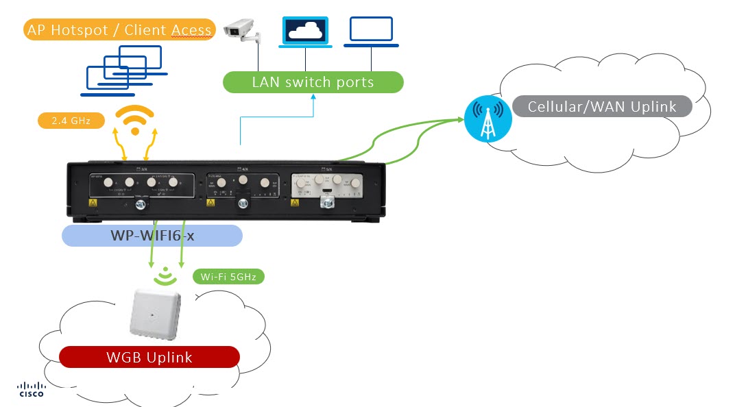
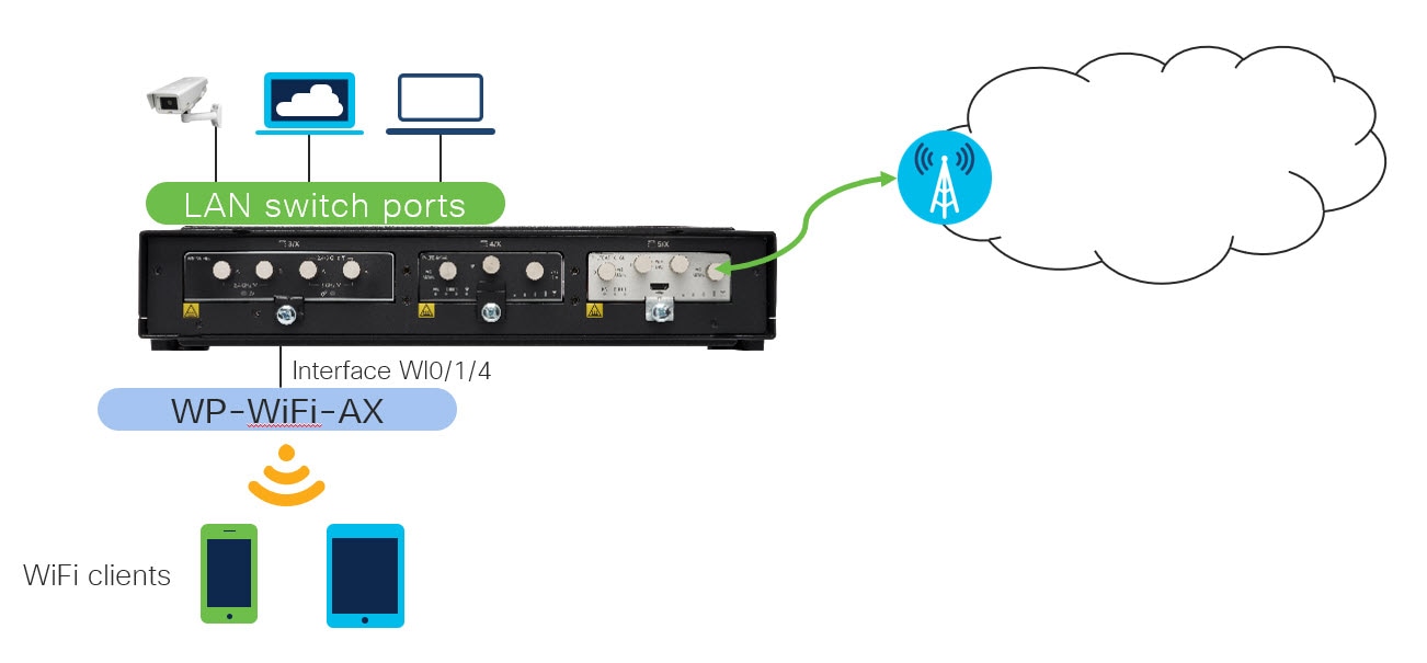
Typical Deployment Modes on the WIM

This chapter contains the following sections:

Typical Deployment Scenarios

Some of the typical scenarios that the WIM can be deployed in are described in this section.

The Wireless Interface Module closely resembles the Cisco Catalyst Series 9105AXI Access Point in functionality.

As a wireless insert module of the host router, it can support provision the WIM module work as a wireless access point (CAPWAP AP mode), then the router can serve the Wi-Fi wireless clients get the network access and at the same time the AP function can be managed by a central wireless controller. In case you do not want to deploy a central wireless controller to manage the AP functions, you can deploy the WIM with EWC mode. Then the host router can still serve the wireless clients network access and at the same time manage the AP function by the local EWC controller.

If you provision the WIM to work in WGB mode, then can configure the host router to use the Wi-Fi wireless connection as a candidate backhaul link. With the 17.11.1 UIW software enhancement, it will give the host router capability to use one radio to serve WGB backhaul, and another radio serve the wireless clients access.

Control And Provisioning of Wireless Access Points (CAPWAP)

The access point uses standard Control and Provisioning of Wireless Access Points Protocol (CAPWAP) to communicate between the controller and other wireless access points on the network. While WP-WIFI6 module working as an access point, it connected directly to a wired LAN provides a connection point for wireless users.

The image used for CAPWAP mode is ap1g8-k9w8.

Prerequisites for Configuring CAPWAP Access Point Configuration on the IR1800

Access points must be discovered by a controller before they can become an active part of the network. CAPWAP does not support Layer 2. The access point must get an IP address and discover the controller using Layer 3, DHCP, DNS, or IP subnet broadcast.

The following section shows the basic configuration of DHCP server and SVI interface on the router for WIM CAPWAP AP to communicate with controller. For modifying additional NAT, DNS and other routing configuration please refer to the IR1800 configuration guide.


Note


If the AP is already in CAPWAP mode, the AP does not reboot. If the AP is in EWC or WGB mode, the AP reboots after which the mode is changed to CAPWAP.

Configuring CAPWAP Access Point Configuration on the IR1800 Procedure

Use the following steps:

Step

Command or Action

Purpose

Step 1

ip dhcp pool name

network ip address subnet mask

default-router ip address

dns-server ip address

option 43 hex <value>

Example:

Router(config)#ip dhcp pool wireless
Router(dhcp-config)#network 10.10.10.0 255.255.255.0
Router(dhcp-config)#default-router 10.10.10.1
Router(dhcp-config)#dns-server 192.0.2.1
Router(dhcp-config)#option 43 hex f108c0a80a05c0a80a14

Create a DHCP server address pool which IP address will be used for Switched Virtual Interface (SVI) Refer Step 4.

Assign default gateway and DNS server address for the pool.

Step 2

interface GigabitEthernet slot/subslot/port

ip address dhcp

ip nat outside

Example:

Router(config)#interface GigabitEthernet 0/0/0
Router(config-if)#ip address dhcp
Router(config-if)#ip nat outside

Configure router Uplink WAN port IP address and use NAT command to connect the interface with the outside network.

Step 3

interface Wlan-GigabitEthernet slot/subslot/port

switchport mode trunk

switchport trunk native vlan number

Example:

Router(config)#interface Wlan-GigabitEthernet 0/1/4
Router(config-if)#switchport mode trunk
Router(config-if)#switchport trunk native vlan 10

Configure switchport mode and native VLAN of WIM internal switch interface. Native VLAN should be AP management VLAN.

Step 4

interface vlan number

description <name>

ip address ip-address subnet_mask

ip nat inside

Example:

Router(config)#interface vlan 10
Router(config-if)#description Wireless
Router(config-if)#ip address 10.10.10.1 255.255.255.0
Router(config)#ip nat inside

Create a Switched Virtual Interface (SVI), assigned IP address from DHCP pool and connect the interface to the inside network.

Step 5

ip route 10.10.10.10 10.10.10.10 default gateway ip-address

Example:

Router(config)#ip route 10.10.10.10 10.10.10.10 192.0.2.1

Direct all the traffic to the default gateway of the router

Step 6

ip nat inside source list number interface GigabitEthernet slot/subslot/port overload

ip access-list standard number

number permit ip address wildcard mask

Example:

Router(config)#ip nat inside source list 10 interface GigabitEthernet 0/0/0 overload
Router(config)#ip access-list standard 10
Router(config)#10 permit 10.10.10.0 0.0.0.255

Establish dynamic source translation, specifying the access list.

Create ACL to permit or deny traffic.

Configuring and Deploying the Access Point

When the Wireless Interface Module is running in CAPWAP mode, once an IP address is set on the module, it communicates and is managed through its WLC, such as a Cisco 9800 series. The configuration process takes place on the controller.

Further information on CAPWAP and Cisco Wireless LAN can be found in the following sources:

Workgroup Bridge (WGB)

The Workgroup Bridge (WGB) scenario offers:

  • Low Cost High-Speed Wi-Fi Uplink

  • Only one radio is allowed to operate in uWGB or WGB mode

  • WGB supports up to 20 wired clients

  • uWGB supports a single client MAC address, for example, VLAN10 interface in a configuration where Wl0/1/4 is a routed interface for Wi-Fi as backhaul link


Important


WGB mode on the IR1800 is only recommended for stationary deployments.

Workgroup Bridge mode is a special mode used for Data Offloading Over Infrastructure Wi-Fi. The WIM running in this mode works like a wireless station. It is normally used to bridge wired clients (connected to it via its Gigabit port) to a wireless infrastructure.

An example usage scenario is to provide Wi-Fi backhaul for cameras and other devices which may be connected to a wired Ethernet port on the IR1800. Note that WGB mode assumes that the wireless infrastructure is from Cisco.

From Cisco IOS-XE Release 17.8.1, the Universal WGB mode is supported for WIM.

Universal WGB (uWGB) is a complementary mode of WGB feature that acts as a wireless bridge between the wired client connected to uWGB and wireless infrastructure including Cisco and non-Cisco wireless network.

For more information on WGB and uWGB configuration, see the following:

Cisco Wave 2 Access Points as Workgroup Bridges

Cisco Industrial Wireless Workgroup Bridge and Universal WGB Deployment Guide

Prerequisites for WGB configuration on the IR1800

The following section shows the basic configuration of the IR1800 to bridge wired client with Infrastructure Wi-Fi traffic. For NAT, ACL and other specific configuration, please refer to the IR1800 configuration guide.

Step

Command or Action

Purpose

Step 1

vlan number-number

Example:

Router(config)#vlan 2001-2002

Create specific VLAN for different wired client traffic VLAN.

VLAN 2001 for wired client Printer.

VLAN 2002 for video camera.

Step 2

interface Wlan-GigabitEthernet slot/subslot/port

switchport mode trunk

switchport trunk allowed vlan number

Example:

Router(config)#interface Wlan-GigabitEthernet 0/1/4
Router(config-if)#switchport mode trunk
Router(config-if)#switchport trunk allowed vlan 2001-2002

Use the Wlan-GigabitEthernet command to connect the Wi-Fi card of the internal switch interface. Configure switchport mode and allowed wired client traffic VLAN passthrough.

Step 3

interface GigabitEthernet slot/subslot/port

description name

switchport mode trunk

switchport trunk native vlan number

interface GigabitEthernet slot/subslot/port

description name

switchport mode access

switchport access vlan number

Example:

Router(config)#interface GigabitEthernet 0/1/0
Router(config-if)#description Printer
Router(config-if)#switchport mode trunk
Router(config-if)#switchport trunk native vlan 2001
Router(config)#interface GigabitEthernet 0/1/1
Router(config-if)#description Camera
Router(config-if)#switchport mode access
Router(config-if)#switchport access vlan 2002

Configure switchport mode and VLAN for each wired client connected port.

Configuring and Deploying WGB

The following section shows the minimum WGB CLI configuration needed on the WP-WIFI6 module. Please follow the guidance in Converting Between Modes to bootup WP-WIFI6 module as WGB first. For further WGB configuration please refer to Cisco Industrial Wireless Workgroup Bridge and Universal WGB Deployment Guide.

Procedure


Step 1

Configure an SSID profile.

Example:

WIM-WGB# configure ssid-profile Test ssid Free authentication psk cisco12345 key-management wpa2

Step 2

Configure radio interface to WGB mode and map the SSID profile. Select authentication as dictated by the wireless infrastructure.

Example:

WIM-WGB# configure dot11Radio 1 mode wgb ssid-profile Test
WIM-WGB# configure dot11Radio 1 encryption mode ciphers aes-ccm
WIM-WGB# configure dot11Radio 1 enable

Step 3

Configure unused radio as root-AP and off. At the time of this writing, single radio is used by WGB.

Example:

WIM-WGB# configure dot11Radio 0 mode root-ap
WIM-WGB# configure dot11Radio 0 disable
WIM-WGB# configure wgb antenna band mode single

Step 4

Check WGB basic configuration by using the show configuration on the WIM.

Example:

WIM-WGB# show configuration
AP Name : WIM-WGB
AP Mode : WorkGroupBridge
SSH State : Enabled
AP Username : Cisco1
Syslog Host : 0.0.0.0

Radio and WLAN-Profile mapping:-
====================================
Radio ID Radio Mode SSID-Profile SSID Authentication
----------------------------------------------------------------------------------------------------------
1 WGB Test Free PSK

Radio configurations:-
===============================
Radio Id : 0
Admin state : DISABLED
Mode : RootAP
Radio Id : 1
Admin state : ENABLED
Mode : WGB

WGB specific configuration:-
====================================
WGB Radio Id : 1
Mode State : Enable
SSID Profile : Test

Antenna Band Mode : Single

Step 5

Check WGB association Uplink State and RSSI using the show wgb dot11 associations command on the WIM.

Example:

WIM-WGB# show wgb dot11 associations

Uplink Radio ID : 1
Uplink Radio MAC : BC:E7:12:0C:FF:6F
SSID Name : Free
Connected Duration : 0 hours, 0 minutes, 5 seconds
Parent AP Name : AP60E6.F0D4.4E34
Parent AP MAC : 60:E6:F0:D4:4A:6A
Uplink State : CONNECTED
Auth Type : PSK
Key management Type : WPA2
Dot11 type : 11ax
Channel : 124
Bandwidth : 40 MHz
Current Datarate : 6 Mbps
Max Datarate : 573 Mbps
RSSI : 40
IP : 192.168.56.107/24
Default Gateway : 192.168.56.1
DNS Server1 : 192.168.71.2
Domain : iottest.local
IPV6 : ::/128
Assoc timeout : 5000 Msec
Auth timeout : 5000 Msec
Dhcp timeout : 60 Sec
Country-code : US

Step 6

Check WGB wired client mac, IP, and vlan id in the bridge table by using the show wgb bridge command on the WIM.

Example:

WIM-WGB# show wgb bridge
***Client ip table entries***
mac vap port vlan_id seen_ip confirm_ago fast_brg
60:E6:F0:D4:4A:6A 0 wbridge1 0 0.0.0.0 24.082000 true
E4:62:C4:49:96:F4 0 wired0 2256 192.168.56.108 6.668000 true

Configuring and Deploying uWGB

The following section shows the minimum uWGB configuration needed on the WP-WIFI6 module. Please follow the procedure listed in Converting Between Modes to bootup WP-WIFI6 module as WGB first. For further uWGB configuration please refer to Cisco Industrial Wireless Workgroup Bridge and Universal WGB Deployment Guide.

Check the show configuration once opening session to 0/3. Review the following:

  • 2.4GHz radio (dot11 radio 0) is turned off

  • The 5GHz radio (dot11 radio 1) is set-up to attach to a 3rd party AP


Note


Either 2.4 GHz or 5 GHz can be configured to uWGB mode.

The following are the high level steps to configure uWGB to connect to a 3rd party app.

Procedure


Step 1

Configure an SSID profile.

Example:

configure ssid-profile Test ssid Free authentication psk cisco12345 key-management wpa2

Step 2

Configure the radio interface to uWGB mode and map the SSID profile. Select authentication as dictated by the wireless infrastructure. In the following example, c44d.849b.0a8c is the uWGB wired client device mac address which gets its address from the infra.

Example:

configure dot11radio 1 mode uwgb c44d.849b.0a8c ssid-profile Test 
configure dot11radio 1 encryption mode ciphers aes-ccm 
configure dot11radio 1 enable

Step 3

Configure the unused radio as root-AP and off. At the time of this writing, single radio is used by uWGB.

Example:

configure dot11radio 0 mode root-ap
configure dot11radio 0 disable

uWGB Configuration Examples

The following are examples of a uWGB configuration.

APBCE7.120C.DAA8#show config
AP Name             : APBCE7.120C.DAA8
AP Mode             : WorkGroupBridge
CDP State           : Enabled 
Watchdog monitoring : Enabled 
SSH State           : Disabled
AP Username         : Cisco
Session Timeout     : 300

Radio and WLAN-Profile mapping:
====================================
Radio ID   Radio Mode   SSID-Profile   SSID   Authentication
1          UWGB         Test           Free   PSK

Radio Configuration:
Radio Id           : 0
  Admin state      : DISABLED
  Mode             : RootAP
  Beacon Period    : 100 mSec 
Radio Id           : 1
  Admin state      : ENABLED
  Mode             : UWGB
  Uclient mac      : C44D.849B.0A8C
  Current state    : WGB 
  UClient timeout  : 0 Sec
  Dot11 type       : 11ax 
  Encryption mode  : AES128

WGB specific configuration:
====================================
WGB Radio Id         : NA
  Mode State         : NA
  SSID Profile       : NA
UWGB Radio Id        : 1
  Mode Enable        : Enable
  SSID Profile       : Test
  Uclient MAC Address: C44D.849B.0A8C

Check attached wired device on the IR1800:

#show wgb bridge
***Client ip table entries***
mac vap                 port  vlan_id   seen_ip       confirm_ago  fast_brg
10:DD:B1:CE:B2:E6       0     wired0    192.168.10.25 0.016000      true

Check the association. In the following example, the Client must be attached to see uWGB status. If there is no traffic from wired client or vice-versa, it falls back to WGB.

#show wgb dot11 associations
Uplink Radio ID       : 1
Uplink Radio MAC      : BC:E7:12:0C:F1:CF
SSID Name             : Free
Parent AP MAC         : 08:02:8E:8D:52:9A
Uplink State          : CONNECTED
Auth Type             : PSK
Key management Type   : WPA2
Uclient mac           : C4:4D:84:9B:0A:8C
Current state         : UWGB
Uclient timeout       : 60 Sec
Dot11 type            : 11ac
Channel               : 36
Bandwidth             : 80 MHz
Current Datarate      : 433 Mbps
Max Datarate          : 1200 Mbps
RSSI                  : 53
IP                    : 0.0.0.0
IPV6                  : ::/128
Assoc timeout         : 5000 Msec
Auth timeout          : 5000 Msec
Dhcp timeout          : 60 Sec

Concurrent Radio Support with uWGB or WGB Uplink and Root AP Modes

Cisco IOS XE 17.11.1 introduced concurrent radio support with WGB uplink and Root AP mode feature in the new Unified Industrial Wireless image(ap1g8t-k9c1). It allows configuring one radio as WGB uplink (2.4G or 5G) and the second radio as WGB Root AP mode for local wireless client serving (also known as hotspot Wi-Fi) independently, or both radios could be configured as Root AP mode.

From 17.14.1 onwards, the WiFi module supports concurrent radio operation, with one radio functioning as an uplink backhaul in uWGB mode and the other as a Root AP radio.

This feature enables to bridge the wireless client traffic with different WLAN-VLAN mapping to internal ethernet port. IR1800 router will route and forward these wireless client traffic to different uplink depends on the use case and configuration.

See the following figure for a typical use case:

Traffic flow for the wireless clients connected to root ap radio (second radio):

  • Client serving radio traffic is not bridged directly to wireless backhaul

  • Wireless client traffic is bridged to the integrated router via internal gig0

  • Wireless clients get their ip address through DHCP from Router’s internal DHCP server

  • Router can then be configured with NAT/ip route to route the packets from wireless clients to infrastructure network and then forward the traffic accordingly (based on the use-case)

Concurrent radio supported scenarios and maximum wireless client limit:

The wireless clients associated and authenticated at the Wi-Fi module client serving radio shall not be updated to infra-Root AP as these are locally serving clients.

  1. First Scenario

    • Radio 0 — WGB mode configured; Status: Disabled (uplink radio Disabled).

    • Radio 1 — Root AP mode; Max 100 wireless clients could be connected.

  2. Second Scenario

    • Radio 0 — WGB mode configured; Status: Enabled (uplink enabled).

    • Radio 1 — Root AP mode; 100 wireless clients supported.

  3. Third Scenario

    • Radio 0 — Root AP mode; 100 wireless clients supported.

    • Radio 1 — Root AP mode; 100 wireless clients supported.


Note


In the above scenarios, the root ap radio and wgb uplink radio can be configured as either Radio 0 or Radio 1 based on the requirement.

Prerequisite Router Configurations for Concurrent Radio Support

This section provides command examples to show the necessary configuration.

Uplink VLAN Configuration on the IR1800:

Unique mac config on Uplink VLAN is a mandatory configuration on the IR1800 for the efficient packet traversing to WP-WIFI6 and vice-versa. The following is an example:


interface Vlan119             ->This is the interface that can carry the data from local network to the infrastructure n/w.
 mac-address c014.fe60.ef8d   ->unique mac address configuration
 ip address dhcp              ->Uplink VLAN gets ip from infra via DHCP
 ip nat outside               ->This config should be done to NAT the downlink/wireless client traffic from vlan 4094 to vlan 119

Note


The unique mac-address derived from Gig0/0/0 mac address + 4

In case of uWGB as uplink, the unique mac address needs to be provided as wired client mac while executing the uWGB configuration CLI.

configure dot11radio <0/1> mode uwgb <c014.fe60.ef8d> ssid-profile <ssid profile name>


In order to obtain the mac address, use the show int GigabitEthernet0/0/0 command:

Router#show int GigabitEthernet0/0/0
GigabitEthernet0/0/0 is administratively down, line protocol is down
  Hardware is IR1821-1x1GE, address is c014.fe60.ef80 (bia c014.fe60.ef80)
  MTU 1500 bytes, BW 1000000 Kbit/sec, DLY 10 usec,
     reliability 255/255, txload 1/255, rxload 1/255
  Encapsulation ARPA, loopback not set
  Keepalive not supported
  Full Duplex, 1000Mbps, link type is auto, media type is Auto Select
  output flow-control is unsupported, input flow-control is unsupported
  ARP type: ARPA, ARP Timeout 04:00:00
  Last input never, output never, output hang never
  Last clearing of "show interface" counters never
  Input queue: 0/375/0/0 (size/max/drops/flushes); Total output drops: 0
  Queueing strategy: fifo
  Output queue: 0/40 (size/max)
  5 minute input rate 0 bits/sec, 0 packets/sec
  5 minute output rate 0 bits/sec, 0 packets/sec
     0 packets input, 0 bytes, 0 no buffer
     Received 0 broadcasts (0 IP multicasts)
     0 runts, 0 giants, 0 throttles
     0 input errors, 0 CRC, 0 frame, 0 overrun, 0 ignored
     0 watchdog, 0 multicast, 0 pause input
     0 packets output, 0 bytes, 0 underruns
     Output 0 broadcasts (0 IP multicasts)
     0 output errors, 0 collisions, 0 interface resets
     0 unknown protocol drops
     0 babbles, 0 late collision, 0 deferred
     0 lost carrier, 0 no carrier, 0 pause output
     0 output buffer failures, 0 output buffers swapped out
Router#

The following is sample wgb bridge table output:

AP84EB.EF55.1438#sh wgb bridge
    ***Client ip table entries*** 
mac vap            port  vlan_id     seen_ip              confirm_ago     fast_brg 
A0:E7:0B:D5:99:95  12    apr0v12     4094  192.168.94.13   158.708000     true 
76:68:82:01:86:C9  13    apr0v13     4094  192.168.94.2    0.000000       true 
C0:14:FE:60:EF:8D  0     wired0      0     10.119.119.229  1.814000       true 

Note


In the bridge table entry only the SVI/ Wired client based on Uplink VLAN(119) and the wireless client based on downlink VLAN will be learnt. The SVI address based on downlink VLAN(4094), will not be learnt here. The uplink VLAN(VLAN 119) configured on IR1800 will be learnt by vlan id '0' since it is the native VLAN.

Downlink VLAN Configuration on the IR1800:

See the following example:


interface Vlan4094           ->Downlink VLAN for wireless client traffic
  ip address 192.168.94.1 255.255.255.0
  ip nat inside              ->Should be provided in the local network VLAN to communicate with infrastructure VLAN

DHCP Pool Configuration for the Downlink VLAN Interfaces:

See the following example:

ip dhcp pool vlan4094  -> Downlink VLAN’s are the used for wireless client(Root ap: WLAN-VLAN mapping)
  network 192.168.94.0 255.255.255.0
  default-router 192.168.94.1
  dns-server 8.8.8.8

Wl0/1/4 Port Configuration:

The following is an example of the Wl0/1/4 port configuration. The internal-Gig0 port to which the AP is connected to the router.

interface Wlan-GigabitEthernet0/1/4 
  switchport trunk native vlan 119
  switchport trunk allowed vlan 119,4094
  switchport mode trunk

Note


The vlan 119 is the wgb uplink vlan and vlan 4094 is the Downlink VLAN used for the traffic of wireless clients.

NAT ACL Configuration:

The following example shows a configuration to create NAT ACL rules.

ip access-list extended NAT_ACL
  10 permit ip 192.168.94.0 0.0.0.255 any
//subnet of Downlink VLAN 4094 interface
   route-map RM_WGB_ACL permit 10   ->Used for Routing table mapping
   match ip address NAT_ACL         ->NAT list used for translation
   match interface Vlan119          ->NAT interface (infrastructure VLAN)

Route Map to Communicate with the Outside Network:

ip nat inside source route-map RM_WGB_ACL interface Vlan119 overload

Note


For additional router topology scenarios, refer to the Cisco Connected Mass Transit System Implementation Guide (Cisco Validated Design).

Configuring Radio Interface as WGB/uWGB and Root AP Mode

The wireless client support requires administrative configurations for various items. To support this feature, the following CLIs are used.

Configure the Unified WGB Mode from CAPWAP Mode

Use the following command:

configure boot mode wgb

Configure the SSID on WGB Uplink or Root AP in Radio Interface

Use the following command:

configure ssid-profile <profile-name> ssid <ssid-name> 
authentication <auth-type> key-management <key-mgmt>

Configure the Radio as WGB Mode

Use the following commands:

configure dot11Radio <0|1> mode wgb ssid-profile <ssid profile name>
configure dot11Radio <0|1> enable

Configure the Radio as uWGB Mode

Use the following commands:

configure dot11Radio<0|1>mode uwgb <client mac> ssid-profile<ssid profile name>

Note


<client mac> - In case of uWGB as uplink, the unique mac address of Router SVI or PC wired client mac can be provided as <wired client mac> while executing the uWGB configuration CLI.

For concurrent root ap radio mode to work if the uplink backhaul is in uWGB mode, provide the unique MAC address of the Router Switched Virtual Interface (SVI) as the 'wired client mac' in the CLI. This step allows the Router SVI to obtain an IP address while the Wi-Fi module is configured in uWGB mode. The Router SVI will be the uplink VLAN, enabling it to forward packets from the downlink VLAN,such as wireless clients, once IP routing or NAT configurations are applied.

For more information, see Prerequisite Router Configurations for Concurrent Radio Support


Configure the Radio as Root-AP Mode

Use the following command:

configure dot11Radio <0|1> mode root-ap

Map the SSID to Root-AP Mode Radio Interface along with VLAN-ID

Use the following commands:

configure dot11Radio <0|1> wlan add <profile-name> <wlan id> vlan <vlan-id>

Note


In the above command, the VLAN creation in client serving radio will be bridged to wired0, so that the traffic from the wireless client will be forwarded directly to the Router. The Wlan id Range is from 2 -16 (Max support 15 wlans).

The root ap related configurations will be saved/taken effect only after toggling the root ap radio.

If Broadcast tagging in wgb is enabled, then the Root AP cannot support wireless client connection. Broadcast tagging configuration will be disabled by default.


configure dot11Radio <0|1> wlan delete <profile-name>

Configure the Radio Channel to Broadcast the SSID for Root-AP Radio Interface

Use the following command:

configure dot11Radio <0|1> channel <channel number> <width>

Note


If radar is detected on a configured channel, then the channel will be changed automatically and will not return to the configured channel.

Configure the Antenna for Radio Interface

Use the following command:

configure dot11Radio <0|1> antenna <dot11 antenna a/ab>

Configure QoS Profile and Attach it to SSID Profile (Optional)

Use the following command:

configure qos profile <qos-prof-name> <bronze|gold|platinum|silver> configure ssid-profile
<profile-name> ssid <ssid> qos profile <qos-prof-name>

Enable or Disable Types of 802.11

Use the following commands:

configure dot11radio <slot-id> 802.11ax <enable/disable>
configure dot11radio <slot-id> 802.11n <enable/disable>
configure dot11radio <slot-id> 802.11ac <enable/disable>

Configure Power Constraint and Channel sw-count

Use the following command:

configure dot11radio <slot-id> 802.11h power-constraint <value> channel-switch-count <value>

Configure tx-power in the Radio Interface

Use the following command:

configure dot11Radio <0|1> tx-power <1-8>

Web Authentication on WGB Root AP

Web Authentication Overview

Web authentication serves as a Layer 3 security feature for setting up guest-access networks. It authenticates through a web browser on a wireless client and allows you to connect to an open SSID without creating a user profile.

From Cisco IOS XE Release 17.15.1, you can configure and customize web authentication on the WGB Root AP. Configuring web authentication activates a captive portal on the WGB Root AP for WP-WIFI6. Agree the terms and conditions on the web portal to gain internet access.

You can configure web authentication to use either a default or a customized web page.

The following figure represents the default captive portal page.

Figure 1. Default Captive Portal Page

Also, you can customize the web authentication to:

  • Redirect the URL of your choice after accepting the captive portal web page.

  • Copy the customized consent web page to WIM and use it for web authentication of WGB Root AP.

  • Allocate a custom virtual interface IP address for the captive portal web page.

  • Add preauthentication Access Control List (ACL) rules to access specific internet destinations before they accept the terms and conditions in a captive portal web page.

    For instance, displaying advertisements from an external website on the current captive portal web page.


Note


Web authentication supports Android, iOS, macOS, and Windows wireless clients.


Web Authentication Process

  1. Connect to Wi-Fi: Select the hotspot SSID and connect to the public Wi-Fi network to establish the connection on your device.

  2. Detect Captive Portal: The device automatically detects the associated captive portal after connecting to the SSID.

  3. Activate Web Authentication: The device activates a web browser, displaying a specific consent web page.

  4. Complete the Authentication: Read and understand the instructions on the web authentication page, then click the Agree & Connect button on the consent web page to accept the terms of service.

  5. Access the Internet: After completing the steps required by the Captive Portal Assistant, you gain internet access through the network.


Note


Client Cache: The device bypasses the consent page upon reconnection within a 5 minutes window after completing web authentication.


Prerequisites of Web Authentication Configuration

Perform the following steps to configure the WiFi module and router.

Procedure

Step 1

Configure radio interface to WGB and root AP mode, see Configuring Radio Interface as WGB/uWGB and Root AP Mode.

Step 2

Configure the router for concurrent radio support, see Prerequisite Router Configurations for Concurrent Radio Support.

Step 3

Configure the router IP Service Level Agreements (SLA) to ping WGB static IP address.

Device(config)#ip sla number 
Example:
Router(config)#ip sla 10
Router(config-ip-sla)#icmp-echo 192.0.2.1 source-interface Vlan4094
Router(config-ip-sl-echoa)#frequency 5
Router(config)#ip sla schedule 10 start-time now

Note

 
  • 192.0.2.1 is the WGB's static IP address and Vlan4094 is the downlink VLAN to communicate between router and WGB.

  • The router's IP SLA pings the WGB's static IP address.

  • If the WGB root AP has a static IP address, you need to activate the WGB's static IP address after a reload by pinging it or initiating a ping from the WGB. Otherwise, the web authentication page will not pop out successfully.

  • The router's IP SLA configuration activates the WGB's static IP address and allows the web authentication page to pop up without manual ping.


Limitations of Web Authentication

Web authentication is designed to support only IPv4 addresses and IP addresses for preauthentication Access Control Lists (ACLs). It does not support Fully Qualified Domain Name (FQDN) ACLs.

Configure a redirect URL is mandatory for Android clients.

Configure Web Authentication Settings

Enable Web Authentication

In the AP, perform these steps to configure the web authentication.

Procedure

Step 1

Run the command to enable the HTTPd service.

Device#configure ap http enable

Note


By default, HTTPd service is enabled. Run the configure ap http disable command to disable the HTTPd service.

Step 2

Run the command to enable web authentication.

Device#configure webauth enable

Note


Run the configure webauth disable command to disable web authentication.

Step 3

Run the command to configure web authentication in Root-AP WLAN.

Device#configure dot11Radio { 0| 1} wlan add < profile-name> < wlan id> vlan < vlan id> webauth { default_webpage/ customized_webpage}

Note


The default web page is webauthpassthrough.html. If required, you can use a custom web page.

If a custom web page is not uploaded to WGB, the AP prints a warning and uses the default web page.

Example:

The following are the examples of default and custom web page configuration:

  • Default web page:

    Device#configure dot11Radio 1 wlan add WebAuth 4 vlan 4094 webauth default_webpage
  • Custom web page:

    Device#configure dot11Radio 1 wlan add WebAuth-customize 5 vlan 4094 webauth customized_webpage
    

Customize Web Authentication Settings

In the AP, perform these steps to customize the web authentication settings:

Procedure

Step 1

Copy the customize web page from the server to WIM storage.

Device#copy webpage {tftp|sftp}://<server-ip>[/dir][/filename]

Device#copy webpage scp://username@<server-ip>[:port]:/dir[/filename]

Note


You can copy a .tar file or an HTML file. The .tar file size should not exceed 10 MB.

Example:
Device#copy webpage scp://root@100.10.10.3:/tftpboot/userid/WebAuth/wp_wifi6_web.tar
copy "scp://root@100.10.10.3:/tftpboot/userid/WebAuth/wp_wifi6_web.tar" to "/storage/webauth/customized_webpage" (Y/N)Y
root@100.10.10.3's password:
wp_wifi6_web.tar                             100%   30KB   6.4MB/s   00:00
[*04/24/2024 08:27:34.1830] wp_wifi6_web/
[*04/24/2024 08:27:34.1830] wp_wifi6_web/logo.jpg
[*04/24/2024 08:27:34.1830] wp_wifi6_web/webauth.css
[*04/24/2024 08:27:34.1830] wp_wifi6_web/reg_customized_webpage.html
[*04/24/2024 08:27:34.1840] % Customized webpage will use wp_wifi6_web/reg_customized_webpage.html as index.html

Save the files to the storage path: /storage/webauth/customized_webpage/. Extract the tar package into this directory and rename the HTML page to index.html.

Step 2

Configure a redirect URL.

Device#configure webauth redirect-url { customized|default} RedirectURL

Example:
Device#configure webauth redirect-url customized https://www.example.com/

Note


To remove the custom redirect URL, use the configure webauth redirect-url default command.

Step 3

Configure a virtual interface in web authentication interface.

Device#configure interface webauth address ipv4 static< interface_ip> < netmask>
Example:
Device#configure interface webauth address ipv4 static 10.10.10.10 255.255.255.255

Note


By default, the web authentication interface uses the IP address 1.1.1.1, which is a virtual interface IP (consent page website IP address).

Step 4

Configure preauthentication ACL.

Device#configure webauthpreauth-acl add < aclrules>
Example:
Device#configure webauth preauth-acl add "allow true and dst 192.168.93.1 mask 255.255.255.0 and ip proto 6”

Sample ACL rules formats are.

  • {allow/deny} {icmp/tcp/udp}

  • {allow/deny} {icmp/tcp/udp} {src/dst} <> [mask] <>

  • {allow/deny} true {and/or} {src/dst} <> [mask] <>

  • {allow/deny} true {and/or} {src/dst} <> [mask] <> {and/or} {ip proto <>}

  • {allow/deny} true

  • {allow/deny} all

  • {allow/deny} true {and/or} {tcp/udp} {src/dst} port <>

Note

 
  • The preauthentication ACL is activated when the client enters the WEBAUTH_REQD state.

  • The maximum length for an ACL rule is 255 characters. There is no limit on the number of ACL entries.

  • To delete the preauthentication ACL, run the configure webauth pre-authentication acl delete command.

  • Deleting a preauthentication ACL clears all preauthentication ACL entries.


Importing and Exporting WGB Configuration

When you want to create a configuration similar to an existing, you can upload the working configuration of an existing WGB to a server, and then download it to the new deployed WGBs.

To upload the configuration to a server, use the following command:

Device#copy configuration upload {sftp:|tftp:|scp:}// ip-address [directory] [file-name]

To download a sample configuration to all WGBs in the deployment, use the following command:

Device#copy configuration download {sftp:|tftp:|scp:}// ip-address [directory] [file-name]

The access point will reboot after the copy configuration download command is executed. The imported configuration will take effect after the rebooting.

Verify Web Authentication

Web Authentication

To verify the web authentication configuration, use the show webauth as shown in the example here.

Device#show webauth

WEBAUTH Configuration are:
====================================
HTTP Status: enabled
Webauth Status: enabled
Webauth Redirect-URL: https://www.example.com/
Webauth Preauth-ACL: allow true and dst 198.51.100.1 mask 255.255.255.0 and ip proto 6, allow icmp dst 198.51.100.1 mask 255.255.255.0,  allow icmp src 198.51.100.1 mask 255.255.255.0
Customized Webpage Exists: Yes
Customized Webpage MD5 HASH: 05ff0f8944e5466e484c342cba6fc403
Web Authentication Current Status

To view the root AP WLAN status, use the show controller dot11radio {0|1} wlan as shown in the example here.

Device#show controllers dot11Radio 1 wlan

apr1v0    Link encap:Ethernet  HWaddr 68:79:09:B8:03:8F
          UP BROADCAST RUNNING MULTICAST  MTU:1500  Metric:1
          RX packets:0 errors:0 dropped:0 overruns:0 frame:60425858
          TX packets:0 errors:0 dropped:0 overruns:0 carrier:0
          collisions:0 txqueuelen:1000
          RX bytes:0 (0.0 B)  TX bytes:0 (0.0 B)
          Interrupt:38

radio vap id               mac               ssid state ml_enabled               mld webauth
    1      3 68:79:09:B8:03:8C            WebAuth    UP         No 00:00:00:00:00:00     Yes
    1      4 68:79:09:B8:03:8B  WebAuth-customize    UP         No 00:00:00:00:00:00     Yes

NON_ML
  intf TxData TxUC TxMBC TxBytes TxFail TxDcrd RxData RxUC RxMBC RxBytes RxErr stats_ago
apr1v3   3051 2976    75 2376573    919      0   2902 2556   346  575037     0  4.196000
apr1v4    427  402    25  289034     31      0    460  344   116   70123     0  4.196000
ML
  intf TxData TxUC TxMBC TxBytes TxFail TxDcrd RxData RxUC RxMBC RxBytes RxErr stats_ago
apr1v3      0    0     0       0      0      0      0    0     0       0     0  4.196000
apr1v4      0    0     0       0      0      0      0    0     0       0     0  4.196000

Vlan BSSID Pri/U/M EncryPolicy Key0 Key1 Key2 Key3 iGTK                 SSIDs MFP
2290   38C   3 3 3       NONE                       DIS               WebAuth   0
2290   38B   3 3 3       NONE                       DIS     WebAuth-customize   0

VAP-ID                  SSID  Bridging Type
     3               WebAuth Local-Switched
     4     WebAuth-customize Local-Switched
Web Authentication Client Status

To verify the client web authentication status, use the show controller dot11radio {0|1} client as shown in the example here.

Device#show controllers dot11Radio 1 client

              mac radio vap aid        state encr  Maxrate Assoc Cap is_wgb_wired      wgb_mac_addr is_mld_sta is_webauth webauth_cached
BC:6E:E2:67:CD:9D     1   3   2 WEBAUTH_REQD OPEN MCS112SS    HE  HE        false 00:00:00:00:00:00         No        Yes             No
00:50:54:27:A2:9F     1   3   1          FWD OPEN MCS112SS    HE  HE        false 00:00:00:00:00:00         No        Yes            Yes

APAP6879.0974.FD08#show client summary

Radio Driver client Summary:
==============================
apr1v3
-------
STA BC:6E:E2:67:CD:9D
	 chanspec 153 (0xd099)
	 state: AUTHENTICATED ASSOCIATED AUTHORIZED
	 per antenna rssi of last rx data frame: -34 -34 0 0
	 per antenna average rssi of rx data frames: -34 -33 0 0
	 per antenna noise floor: -82 -84 0 0
smoothed rssi: -33
tx nrate
he mcs 9 Nss 2 Tx Exp 0 bw20 ldpc 2xLTF GI 1.6us auto
rx nrate
he mcs 9 Nss 2 Tx Exp 0 bw20 ldpc 4xLTF GI 3.2us auto

apr1v4
-------

WCP client Summary:
=====================

              mac radio vap aid        state encr  Maxrate Assoc Cap is_wgb_wired      wgb_mac_addr is_mld_sta is_webauth webauth_cached
BC:6E:E2:67:CD:9D     1   3   2 WEBAUTH_REQD OPEN MCS112SS    HE  HE        false 00:00:00:00:00:00         No        Yes             No

Assoc time:
=============
              mac      assoc_time
BC:6E:E2:67:CD:9D 00d:00h:04m:08s

Note


Before you accept the consent page, the client state is WEBAUTH_REQD, and after the web authentication is complete, the client state changes to FWD (forward).


Preauthentication ACL

To view the client's current preauthentication ACL, use the show client access-lists pre-auth all client mac-address as shown in the example here.

Device#show client access-lists pre-auth all BC:6E:E2:67:CD:9D
Pre-Auth URL ACLs for Client: BC:6E:E2:67:CD:9D
IPv4 ACL: PREAUTH
IPv6 ACL:
ACTION    URL-LIST
Resolved IPs for Client: BC:6E:E2:67:CD:9D
HIT-COUNT      URL        ACTION    IP-LIST
PREAUTH
    rule 0: allow true and dst 198.51.100.1 mask 255.255.255.0 and ip proto 6
    rule 1: allow icmp dst 198.51.100.1 mask 255.255.255.0
    rule 2: allow icmp src 198.51.100.1 mask 255.255.255.0

No IPv6 ACL found
Redirect URL for client: BC:6E:E2:67:CD:9D

Acl name Quota Bytes left In bytes Out bytes In pkts Out pkts Drops-in Drops-out
 PREAUTH     0          0        0       148       0        2       21       201
CLIENT STATE: WEBAUTH_REQD
WEBAUTH_REQUIRED: TRUE
DNS POST AUTH:  FALSE
PREAUTH ENABLED: TRUE
POSTAUTH ENABLED: FALSE

Cisco Embedded Wireless Controller (EWC)

The Embedded Wireless Controller (EWC) scenario offers:

  • Self-Management

  • Traffic Local-Switching

  • May manage cascaded AP, aligned on C9105 + IR1800 performances

  • WebUI management

  • Cisco Catalyst Wireless Mobile Application (iPhone/Android)

EWC mode is typically used for Mass Transit/Transportation Remote & Mobile Assets.

When the Wireless Interface Module is running in EWC mode, it acts as a wireless controller and an Access Point (usually called internal AP). EWC manages other APs in a similar way as dedicated wireless controller (like C9800 series).

In a Cisco EWC network, an Access Point (AP) running the wireless controller function is designated as the active AP. The other access points, which are managed by this active AP, are referred to as subordinate APs.

The image used for EWC mode is C9800-AP-iosxe-wlc.bin.

The active EWC has two roles:

  • Functions and operates as a Wireless LAN Controller (WLC) to manage and control the subordinate APs. The subordinate APs operate as lightweight access points to serve clients.

  • Operates as an access point to serve clients.

For Wi-Fi landing page feature (Web-based authentication) support, see the Web-Based Authentication chapter in the Cisco Embedded Wireless Controller on Catalyst Access Points Configuration Guide.

Further information on the Cisco Embedded Wireless Controller can be found in the following:

Cisco Embedded Wireless Controller on Catalyst Access Points FAQ

Cisco Embedded Wireless Controller on Catalyst Access Points (EWC) White Paper

Prerequisites for Configuring EWC Access Point on the IR1800

Before configuring the EWC Access Point on the router, ensure the following prerequisites are met:

  • It is recommended not to have any other Cisco Wireless LAN Controllers; neither appliance nor virtual in the same network during set up or during daily operation of a Cisco Embedded Wireless Controller (EWC) network.

  • A DHCP server must be available on the network so that Access Points and clients can obtain an IP Address.

  • To configure the EWC and AP integrated into IR1800 series router, you must configure a DHCP server, SVI interface, and NAT on the router. For more information on configuring the AP, see the Prerequisites for Configuring CAPWAP Access Point Configuration on the IR1800 section.

  • On an Embedded Wireless Controller (EWC), management traffic is untagged and should be configured as native VLAN on the switch port. If the WIM and WLANs are all on different VLANs, the WIM connected port on the router need to be configured as trunk and traffic for individual WLANs will be switched locally on individual VLANs. Shown below is a router configuration with WIM and WLANs on different VLANs:

    Command

    Purpose

    interface Wlan-GigabitEthernet slot/subslot/port

    switchport mode trunk

    switchport trunk native vlan number

    switchport trunk allowed vlan numbers

    Configure switchport mode and native VLAN of WIM internal switch interface. Native VLAN 10 should be AP management VLAN. VLAN 20 and 30 used for WLAN traffic.

See the following example:

Router(config)#interface Wlan-GigabitEthernet 0/1/4
Router(config-if)#switchport mode trunk
Router(config-if)#switchport trunk native vlan 10
Router(config-if)#switchport trunk native vlan 10,20,30

Configuring EWC Using Day 0 Provisioning

There are three ways to configure the AP using day 0 provisioning:

  1. To connect the SSID to CiscoAirProvision-XXXX, follow the steps in Deploying the EWC.

  2. You can also scan the QR Code by using the Catalyst Wireless Application on a mobile phone. Follow the steps in the User Guide for Cisco Catalyst Wireless Mobile Application.

  3. You can manually configure the AP using CLI by following the steps in Configuring the Controller Using Day 0 Wizard (CLI), or performing the basic configuration manually by following the steps in Option 1. Initial CLI Configuration in the Convert Catalyst 9100 Access Points to Embedded Wireless Controller.

Other items to consider are:

  • For day 0 configuration done through the WebUI or Cisco Wireless Mobility application, it is recommended to reload the Wi-Fi module making sure it obtains an IP address from configured VLAN pool, for example, VLAN10.

  • For WebUI day 0, it may not work if using an IP address different from the default IP address:192.168.0.1, which also collides with day0 IP address of the IR1800 IOS-XE.

Connecting Cisco Embedded Wireless Controller (EWC) Capable Access Point to the Network

Depending on the deployment, Embedded Wireless Controller (EWC) Capable Access Point connected to the router port can be configured as an Access port or a Trunk port.

If Access Points and WLANs are all on the same network, Embedded Wireless Controller (EWC) capable Access Points can connect to router by access mode as shown in the following example.

interface Wlan-GigabitEthernet 0/1/4 
switchport access vlan 10
switchport mode access

On an Embedded Wireless Controller (EWC), management traffic is untagged. If Access Points and WLANs are all on different VLANs, the Embedded Wireless Controller (EWC) capable Access Points will connect to a trunk port on the switch and traffic for individual WLANs will be switched locally on individual VLANs. Shown in the example below is a deployment with Access Points and WLANs on different VLANs.

interface Wlan-GigabitEthernet 0/1/4 
switchport trunk native vlan 10
switchport trunk allowed vlan 10,20,30
switchport mode trunk

EWC Mode WebUI Management

This section provides steps for configuring the WIM in EWC mode through the WebUI.

Day 0 Provisioning Using the Over-The-Air WebUI Setup Wizard

When the AP has rebooted in the Embedded Wireless Controller (EWC) mode, it broadcasts a provisioning SSID ending with the last digits of the MAC address. You can connect to provisioning SSID using the PSK password.

You can then open a browser and be redirected to mywifi.cisco.com, which takes you to the AP web UI. Enter the username as webui and password as cisco. Seeing further day0 configuration steps in following link: https://www.cisco.com/c/en/us/products/collateral/wireless/embedded-wireless-controller-catalyst-access-points/white-paper-c11-743398.html#DeployingtheEWC


Note


The web redirection to the Embedded Wireless Controller (EWC) configuration portal only works if you are connected to the provisioning SSID. It does not work if your laptop is connected to another Wi-Fi network or on the wired network. You cannot configure the AP from the wired network even if you enter the EWC IP address when it is in day0 wizard provisioning mode.

Logging in to the EWC WebUI

To log in to the EWC, perform the following steps:

Procedure

Step 1

Open the WebUI from a browser. Use the IP address allocated from DHCP.

Step 2

The WebUI dashboard appears.

Step 3

Once connected to the Wireless LAN Controller (WLC), configuration is performed as any other access point. Refer to the following resources for additional information:

Overview of Cisco Embedded Wireless Controller on Catalyst Access Points

Cisco Embedded Wireless Controller on Catalyst Access Points Configuration Guide, IOS XE