Installing the External Power Supply Chassis
Available Languages
Table Of Contents
Installing the Cisco External Power Supply Chassis
Setting the Cisco External Power Supply on a Desktop
Rack-Mounting the Cisco External Power Supply
Planning Your Rack-Mount Installation
Identifying Rack-Mount Brackets
Mounting the Chassis in a Rack
Connecting the Power Grounding Lug
Installing the Cisco External Power Supply Chassis
You can set the Cisco external power supply chassis on a desktop or install it in a rack.

Warning
Only trained and qualified personnel should be allowed to install or replace this equipment. To see translations of the warnings that appear in this publication, refer to the Regulatory Compliance and Safety Information document that accompanied your equipment.
Warning
Warning
Warning
Warning
Warning
•
•
The Cisco external power supply location is extremely important for proper operation. Equipment placed too close together, inadequate ventilation, and inaccessible panels can cause malfunctions and shutdowns and can make maintenance difficult. The following information will help you to plan the location of the chassis.
•
•
Use the procedure that best meets your needs:
•
•
Setting the Cisco External Power Supply on a Desktop
Warning
Warning
Follow these steps to install your chassis on a desktop:
Step 1
Step 2
Step 3
Step 4
Step 5

Note
Rack-Mounting the Cisco External Power Supply
This sections explains how to rack-mount the Cisco external power supply in 19-, 23-, 24-inch, or telco equipment racks. Read the following information before rack-mounting your chassis.
Planning Your Rack-Mount Installation
Warning
•
•
•
To see translations of the warnings that appear in this publication, refer to the Regulatory Compliance and Safety Information document that accompanied your equipment.
The following information will help you plan your equipment rack installation:
•
•
•
•
•
Tools and Equipment Required
You need the following tools and equipment to rack-mount the Cisco external power supply:
•
•
•
–
–
–
Identifying Rack-Mount Brackets
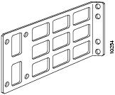
Figure 2-1 shows the 19-, 23-, and 24-inch brackets and Figure 2-2 shows the telco bracket.
Figure 2-1 19-, 23-, and 24-inch Rack-Mount Brackets
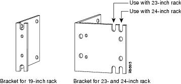
Figure 2-2 Telco Bracket
Attaching Brackets
To install the Cisco external power supply in a rack, attach the brackets in one of the following ways:
•
•
•
Note
Figure 2-3 Bracket Installation—External Power Supply Front Panel Forward

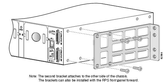
Figure 2-4 Bracket Installation—External Power Supply Rear Panel Forward
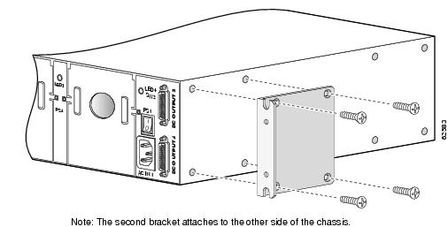
Figure 2-5 Telco Bracket Installation—External Power Supply Rear Panel Forward
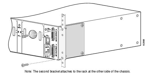
Mounting the Chassis in a Rack
After the brackets are secured to the chassis, use your own screws to attach the chassis to the rack, as shown in Figure 2-6.
Install the AC power cords. If you are just using power modules in slots 1 or 2, plug in just the AC1 cable. If you are just using power modules in slots 3 or 4, plug in just the AC2 cable.
Figure 2-6 Attaching the Chassis to a Rack—Rear Panel Forward
Connecting the Power Grounding Lug
To attach the grounding lug to your chassis, complete the following tasks:
Step 1
Step 2
Step 3
Figure 2-7 Crimping the Lug Around the Wire

Step 4
Step 5
Figure 2-8 Grounding Lug Fastened to External Power Chassis


Caution
This equipment is suitable for connection to intrabuilding or nonexposed wiring or cabling only. This cabling must be shielded.
Step 6
 Feedback