External Power Supply Overview
Available Languages
Table Of Contents
Cisco External Power Supply Overview
Front and Rear Panel Descriptions
Cisco External Power Supply Overview
The Cisco external power supply provides -48V power for inline IP telephony support for the Cisco Ethernet switch network modules. The system includes two AC power inputs and four DC output power modules for connection to external devices. The Cisco external power supply supports redundant configurations.
This chapter provides an overview of the Cisco external power supply features in the following sections:
•
"Power Configurations" section
•
•
Features
The following features are standard:
•
•
•
•
•
–
–
–
Power Configurations
The Cisco external power supply can supply power to the Cisco Ethernet switch network module in three ways:
The AC power sources support the DC power supplies shown in Table 1-1.
Each power supply module can provide up to 360W, which is enough power for up to 36 IP phones at 10W each.
One-to-One Connection
In a one-to-one configuration, one of the DC outputs from the Cisco external power supply connects to one Cisco Ethernet switch network module, as shown in Figure 1-1.
Figure 1-1 One-to-One Configuration
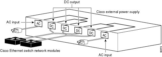
One-to-Two Connection
In a one-to-two configuration, one of the DC outputs from the Cisco external power supply connects to two 16-port Cisco Ethernet switch network modules, as shown in Figure 1-2.
Each power supply module can provide up to 360W, which is enough power for up to 36 10W IP phones. If using the 16-port Cisco Ethernet switch network module, then two network modules can be powered by one power supply module.You can use a one-to-two cable (ordered separately) to connect the power module to two Ethernet power supply modules.

Note
The connectors at one end of the Y-shaped cable connect to two Cisco Ethernet switch network modules; the single connector on the other end of the cable connects to one Cisco external power supply DC output power module.
Figure 1-2 One-to-Two Configuration

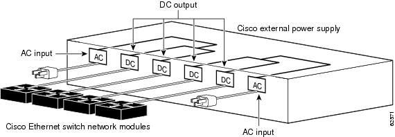
Redundant Connection
The Cisco external power supply can provide a fully redundant power source for two of the supported Cisco Ethernet switch network modules. You can use a two-to-one cable (ordered separately) to connect an Ethenet switch network module to two DC output power modules, as shown in Figure 1-3. The two-to-one cable is a Y-shaped cable with two connectors at one end and one connector at the other end.
In this configuration, the connectors at one end of the Y-shaped cable connect to two DC ouputs on the Cisco external power supply; the single connector on the other end of the cable connects to one Cisco Ethernet switch network module. The power source is fully redundant because there are two AC inputs and two DC output power modules connected to each external device. If any power module fails due to AC input failure or DC module failure, there is a full backup.
Figure 1-3 Fully Redundant Configuration
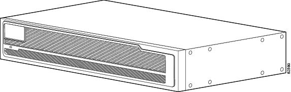
Front and Rear Panel Descriptions
The LEDs on the Cisco external power supply front panel show the Cisco external power supply operational status. Figure 1-4 illustrates the front panel of the Cisco external power supply.
Figure 1-4 Cisco External Power Supply Front Panel
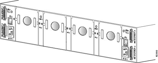
The Cisco external power supply rear panel has two AC power connectors, each with an on/off switch, and four DC connectors for connecting to devices.There is an LED for each module slot. Figure 1-5 shows the rear panel. Refer to "Connecting the Cisco External Power Supply to the Cisco Ethernet Switch Network Modules," for information about required cables and connectors.
Figure 1-5 Cisco External Power Supply Rear Panel
LEDs
The Cisco external power supply has an LED on the front of the chassis and on each external power supply module slot. The LEDs on the front panel of the Cisco external power supply display the current operating condition of the Cisco external power supply. The LEDs on the individual module slots display the status of that module. When the Cisco external power supply is working properly, all LEDs on its front panel and each individual module slot that has a module installed are solid green.
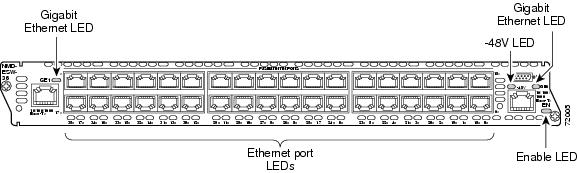
Figure 1-6 shows the external power supply front panel LED, Figure 1-7shows the rear panel LEDs, and Figure 1-8 and Figure 1-9 show the 16- and 36-port Cisco Ethernet switch network module LEDs. Table 1-2 explains the meaning of the LED colors for the front and rear panels of the external power supply chassis and Table 1-3 explains the meaning of the LED colors for the rear chassis LEDs and Cisco Ethernet switch network module.
When checking for potential problems with the power delivery, perform the following steps before checking the LEDs:
Step 1
Step 2
Step 3
Step 4
Step 5
Figure 1-6 Cisco External Power Supply Front Panel LED
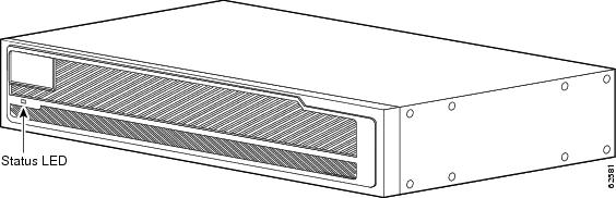
Figure 1-7 Cisco External Power Supply Rear Panel LEDs
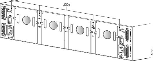
Figure 1-8 16-Port Cisco Ethernet Switch Network Module LEDs
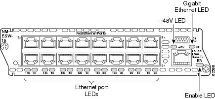
Figure 1-9 36-Port Cisco Ethernet Switch Network Module LEDs
Safety Recommendations
Follow these guidelines to guarantee general safety:
•
•
•
•
•
Safety Warnings
Safety warnings appear throughout this guide in procedures that, if performed incorrectly, might harm you. A warning symbol precedes each warning statement.
Safety with Electricity

Warning
Warning
Warning
Warning
Warning
Warning
Warning
Follow these guidelines when working on equipment powered by electricity:
•
•
•
–
–
–
–
 Feedback