Connecting the External Power Supply to the Ethernet Switch Network Module
Available Languages
Table Of Contents
Connecting the
Cisco External Power Supply to the Cisco Ethernet Switch Network ModulesConnecting the Cisco External Power Supply to the Network Module
Connecting a One-to-One Configuration
Connecting a One-to-Two Configuration
Connecting a Redundant Two-to-One Configuration
Connecting the
Cisco External Power Supply to the Cisco Ethernet Switch Network Modules
This chapter describes the equipment required to connect the Cisco external power supply to the Cisco Ethernet switch network modules installed in Cisco 2600 series, Cisco 3600 series, and Cisco 3700 series routers. The Cisco external power supply includes four DC output power modules for inline power for IP telephony.
This chapter contains the following sections:
•
"Tools and Equipment Required" section
•
Tools and Equipment Required
You might need to order the following equipment:
•
•
•
Cabling Options
The external power supply can supply power to the Cisco Ethernet switch network module in three ways:
•
•
•
These connection types are described in the "Power Configurations" section.
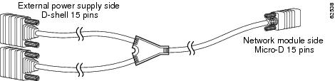
Figure 5-1, Figure 5-2, and Figure 5-3 show the cables you can order. For ordering information, contact 800 553-6387, 408 526-7208, or cs-rep@cisco.com. See also the "Obtaining Technical Assistance" section.
Figure 5-1 One-to-One Cable
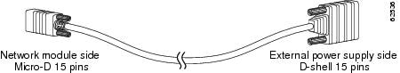
Figure 5-2 One-to-Two Y-Shaped Cable
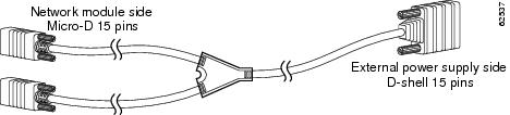
Figure 5-3 Two-to-One Y-Shaped Cable
Connecting the Cisco External Power Supply to the Network Module
This section explains how to connect the Cisco external power supply to the Cisco Ethernet switch network module. The power module is connected to a Cisco external power supply using a power connection cable. Your procedure will depend on the type of connection you are performing, as follows:
•
•
•
Connecting a One-to-One Configuration
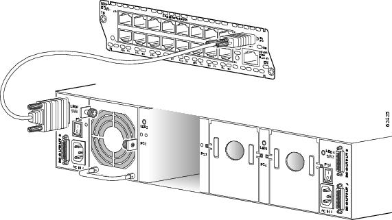
Perform the following steps to connect the Cisco external power supply to the Cisco Ethernet switch network module:
Step 1
Step 2

Caution
Step 3
Figure 5-4 Connecting the Cisco External Power Supply to the Cisco Ethernet Switch Network Module
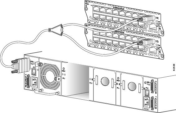
Connecting a One-to-Two Configuration
Perform the following steps to connect the Cisco external power supply to two Cisco Ethernet switch network modules:
Step 1
Step 2
Step 3
Caution

Note
Step 4
Figure 5-5 Connecting the Cisco External Power Supply to Two Cisco Ethernet Switch Network Modules
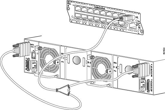
Connecting a Redundant Two-to-One Configuration
Perform the following steps to connect the Cisco external power supply to the Cisco Ethernet switch network module:
Step 1
Step 2
Caution
Step 3
AC input 1
DC module 1
DC module 2
AC input 2
DC module 3
DC module 4
Caution
Step 4
Figure 5-6 Connecting Redundant Cisco External Power Supplies to the Cisco Ethernet Switch Network Module
 Feedback