Replacing Power Supply Modules
Available Languages
Table Of Contents
Replacing Power Supply Modules
Removing the Power Supply Module
Installing the Power Supply Module
Replacing Power Supply Modules
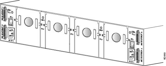
The Cisco external power supply accommodates four DC hot-swappable power supply modules. Each module provides -48V of power, and a single installed power supply module meets the inline telephony requirements. Additional installed power supply modules provide redundancy, load sharing, and increased system availability. When no cables are connected, DC power supply modules can be removed or inserted without affecting system operation.
Figure 3-1 shows the DC power supply modules for the external power supply, Figure 3-2 shows the location of the power supply module in the external power supply chassis.
Figure 3-1 Power Supply Modules
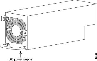
Figure 3-2 Rear View of the Cisco External Power Supply Chassis
Tools and Equipment Required
You need the following tools and equipment to remove and install power supplies in an external power supply chassis:
•
Number 2 Phillips screwdriver
•
•
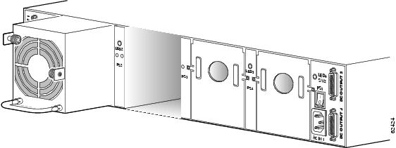
Removing the Power Supply Module
Use the following procedure to remove a power supply module:
Step 1
Step 2
Step 3
Step 4
Figure 3-3 Removing a Power Supply
Installing the Power Supply Module
Use the following procedure to install a power supply:
Step 1
Step 2
Step 3
Step 4
 Feedback