Hardware Features of the Cisco ASR 1001-X Router
The Cisco ASR 1001-X Router supports:
- Up to 16 GB (8 GB in the base configuration) of DDR3 error-correcting code-protected field- replaceable memory, with single-bit error correction and multi-bit error detection.
- A nonmodular and fixed Embedded Services Processor (ESP) with a default throughput of 2.5 Gbps that is upgradable with a software-activated performance license of 5 Gbps, 10 Gbps, or 20 Gbps.
- Up to 8 Gbps security and crypto processing through a dedicated security processor.
- RJ-45 console ports and auxiliary ports, and a mini USB console port.
- One copper Ethernet 10/100/1000 Mbps network management port.
- An embedded USB (eUSB) flash module that supports 8 GB of nonvolatile Flash storage.
- Two USB 2.0 ports for USB flash sticks or USB secure tokens (secure key distribution).
- Stratum 3E network clocking per GR-1244-CORE, using 1588, 10 GE, GE, SPA, or Network Interface Module (NIM) interfaces as timing sources.
- Six built-in 1 GE SFP-only interfaces (do not support SFP+), and two built-in 10 GE SFP+ interfaces (support only 10-GE rate) that support SyncE.
- One half-height SPA bay.
- Software redundancy using Dual IOS, similar to all the other nonhardware redundant routers from the Cisco ASR 1000 Series Aggregation Services Router family.
- LED indicators for Ethernet and console status, as well as visual system state indications.
- Command-line interface (CLI), alarm, network management, logging, statistics aggregation, and on-board failure logging (OBFL).
- Environmental chassis management.
- 10 MB ternary content-addressable memory (TCAM).
- Up to 20 Gbps sustained forwarding data traffic through the chassis.
- One Network Interface Module (NIM) bay.
 Note |
The NIM bay supports the T1/E1 NIMs and the Solid State Device (SSD) NIM assembly and drive. |
- Field-replaceable units (FRU) with online insertion and removal (OIR).
Cisco ASR 1001-X Overall Chassis Front View
The following figure shows the front of the Cisco ASR 1001-X Router.

|
1 |
NIM slots |
7 |
Shared port adapter slot |
|
2 |
CON—One mini eUSB por |
8 |
USB port 0 |
|
3 |
PWR—Power LED |
9 |
USB port 1 |
|
4 |
Six built-in 1 GE SFP-only interfaces (do not support SFP+), and two built-in 10 GE SFP+ interfaces (support only 10-GE rate) |
10 |
CON—One RJ-45/RS-232 compatible console port |
|
5 |
AUX—One RJ-45/RS-232 compatible auxiliary port |
11 |
CRIT LED—Critical alarm indicator MAJ LED—Major alarm indicator MIN LED—Minor alarm indicator |
|
6 |
MGMT—One RJ-45 10/100/1000 management Ethernet port. The management port has two LEDs, L and S. L green indicates Link operations. S blinks the negotiated Ethernet speed (1 blink equals 10 Mbps, 2 blinks equals 100 Mbps, 3 blinks equals 1 000 Mbps). |
12 |
STAT—Status LED |
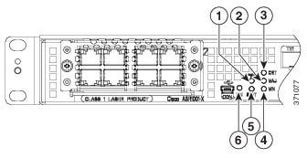
Cisco ASR 1001-X Router LEDs
The following figure shows the front panel of the Cisco ASR 1001-X Router.

|
No. |
LED Label |
LED |
Color |
Behavior in the Power-Up State |
|---|---|---|---|---|
|
1 |
PWR |
Power |
Green |
All the power supplies are within operational limits. |
|
2 |
MAJ |
MAJOR |
Red |
Major alarm indicator. |
|
3 |
CRIT |
CRITICAL |
Red |
Critical alarm indicator. Will be off when the router is initially powered up and all the configured components are available. |
|
4 |
MIN |
MINOR |
Amber |
Minor alarm indicator |
|
5 |
STAT |
STATUS |
Green |
Cisco IOS has successfully booted. |
|
Yellow |
The system is at ROMMON. |
|||
|
Red |
System failure. Will be off when the router is powered up. |
|||
|
6 |
EN |
USB Console Enable |
Green |
Indicates that the mini eUSB connector is used as the console. |
|
Off |
Indicates that the RJ-45 connector is being used as the console. |
Cisco ASR 1001-X Management Storage Connections
The following figure shows the Cisco ASR1001-X Router’s management storage connections.

|
1 |
AUX—One RJ-45/RS-232 compatible auxiliary port. |
4 |
USB port 1 |
|
2 |
MGMT —one RJ-45 10/100/1000 management Ethernet port. The Management Port has two LEDs, L and S. L green indicates Link operations. S blinks the negotiated Ethernet speed (1 blink 10 Mbps, 2 blinks 100 Mbps, 3 blinks, 1 000 Mbps). |
5 |
CON—One RJ-45/RS-232 compatible console port |
|
3 |
USB port 0 |
— |
Cisco ASR 1001-X Chassis Rear View
The following figure shows the rear of the Cisco ASR 1001-X Router with four fans and two AC or DC power supplies.

Four internal fans draw cooling air into the chassis and across internal components to maintain an acceptable operating temperature. The fans are located in the center of the chassis. The fans are numbered from 0 to 3, right to left.
Two power supplies, either two AC power supplies or two DC power supplies are accessed from the rear of the router and are hot-swappable.
 Note |
The Cisco ASR 1001-X Router can support two AC or two DC power supplies. Do not install mixed AC and DC power supply units in the same chassis. |
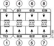
Cisco ASR 1001-X SPA GE and TE Ports
The 10 GE SFP+ ports are indicated in the front bezel with orange highlights, and the GE SFP ports are indicated with yellow highlights. The following figure shows the port numbering for the 10 GE SFP+ and GE SFP ports.

|
1 |
10 GE SFP+ Port 0/0/0 |
5 |
GE SFP Port 0/0/2 |
|
2 |
10 GE SFP+ Port 0/0/1 |
6 |
GE SFP Port 0/0/3 |
|
3 |
GE SFP Port 0/0/0 |
7 |
GE SFP Port 0/0/4 |
|
4 |
GE SFP Port 0/0/1 |
8 |
GE SFP Port 0/0/5 |


 Feedback