Verifying Hardware Installation

After installing the Cisco ASR 1000 Series Aggregation Services Router or replacing any of its hardware components that are field-replaceable units (FRUs), verify the installation.

This chapter includes the following sections:

Checking the LEDs

Check the LEDs on the faceplates of the following FRUs:

Cisco ASR 1000 Series Route Processors

Route processor LEDs vary according to the chassis model, as described in the following sections.

Cisco ASR 1013 Router

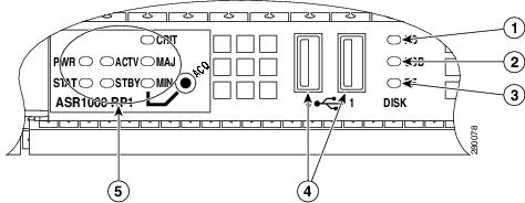
Table 1-1 shows the color or state of the LEDs in the Cisco ASR 1000 Series Route Processor-2 (RP-2) that indicate a successful installation. Figure 1-1 shows a view of the LEDs on the faceplate.


Note Only Route Processor-2 (RP-2) and ESP-40 (Embedded Service Processor) are supported for installation on the Cisco ASR 1013 Router.


Table 1-1 RP-2 Faceplate LEDs Indicating a Successful Installation (Cisco ASR 1013 Router)

LED Label
Color—State
Description

PWR

Solid green

All power requirements are within specification


Off

Off indicates that the router is in standby mode.

STAT

Solid green

Cisco IOS has successfully booted.


Yellow

BOOT ROM has successfully loaded.


Red

System failure.

ACTV

Green

Lit when this is the active ASR 1000 Series route processor (Cisco ASR1000-RP1 or Cisco ASR1000-RP2).

STBY

Yellow

Lit when this is the standby ASR 1000 Series route processor.

CRIT

Solid red

Critical alarm indicator. This is on at power up, turned off by software.

MAJ

Solid red

Major alarm indicator.

MIN

Amber

Minor alarm indicator.

DISK HD

Flashing green

Active indicator.

Off

No activity.

DISK USB

Flashing green

Active indicator.

Off

No activity.

DISK BF

Flashing green

Active indicator.

Off

No activity.

Figure 1-1 RP-2 Faceplate LEDs for an Active RP (Cisco ASR 1013 Router)


Cisco ASR 1001 Router

The Cisco ASR 1001 Router faceplate has common components for each type of ASR 1001 Router configuration. Figure 1-2 shows the Cisco ASR1000 front panel LEDs of the Cisco ASR 1001 Router. Table 1-2 shows the color or state of the LEDs in the Cisco ASR 1001 Series Router.

Figure 1-2 Common LEDs for Cisco ASR 1001 Router
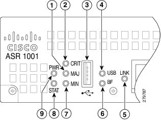
 

Table 1-2 Cisco ASR 1001 LED Color or State Details

LED Label
Color—State
Description

PWR

Solid green

Power requirements are within specification.

STAT

Solid green

Cisco IOS booted successfully.

MIN

Off

No minor alarms.

MAJ

Off

No major alarms.

CRIT

Off

No critical alarms.

BF

Green

Indicates activity of the EUSB device

Link

Green

Solid Green indicates Link, Flashing green indicates MGMT Ethernet port activity.

USB

Green

USB is green and flashes when accessed.

Cisco ASR 1004 Router, Cisco ASR 1006 Router

Table 1-3 shows the color or state of the LEDs in the Cisco ASR 1000 Series Route Processor (RP) that indicate a successful installation. Figure 1-3 shows a view of the LEDs on the faceplate.

Table 1-3 RP LEDs Indicating a Successful Installation (Cisco ASR 1004 Router, Cisco ASR 1006 Router)

LED Label
Color—State
Description

PWR

Solid green

Power requirements are within specification.

STAT

Solid green

Cisco IOS booted successfully.

ACTV

Green

Active RP.

STBY

Yellow

Standby RP.

CRIT

Off

No critical alarms.

MAJ

Off

No major alarms.

MIN

Off

No minor alarms.

Figure 1-3 RP Faceplate LEDs for an Active RP (Cisco ASR 1004 Router, Cisco ASR 1006 Router)


Cisco ASR 1002 Router

Table 1-4 shows the color or state of the LEDs in the Cisco ASR 1000 Series Route Processor (RP) that indicate a successful installation. Figure 1-4 shows a view of the LEDs on the faceplate.

Table 1-4 RP LEDs Indicating a Successful Installation (Cisco ASR 1002 Router)

LED Label
Color—State
Description

pwr

Solid green

Power requirements are within specification.

stat

Solid green

Cisco IOS booted successfully.

min

Off

No minor alarms.

maj

Off

No major alarms.

crit

Off

No critical alarms.

Figure 1-4 RP Faceplate LEDs for an Active RP (Cisco ASR 1002 Router)


Cisco ASR 1000 Series Embedded Services Processors

Table 1-5 shows the color or state of the LEDs in the Cisco ASR 1000 Series Embedded Services Processor (ESP) that indicate a successful installation. Figure 1-5 shows a view of the LEDs on the faceplate.

Table 1-5 ESP LEDs Indicating a Successful Installation

LED Label
Color—State
Description

PWR

Solid green

Power requirements are within specification.

STAT

Solid green

Cisco IOS booted successfully.

ACTV

Green

Active ESP.

STBY

Yellow

Standby ESP.

Figure 1-5 ESP Faceplate LEDs for an Active ESP


Cisco ASR 1013 Router

Table 1-6 shows the color or state of the LEDs in the Cisco ASR 1000 Series SPA Interface Processors (SIP) that indicate a successful installation. Figure 1-6 shows a view of the LEDs on the faceplate.

Table 1-6 SIP LEDs Indicating a Successful Installation (Cisco ASR 1013 Router)

LED Label
Color—State
Description

PWR

Solid green

SIP is powered on.

STATUS

Solid green

SIP is online.

In the Cisco ASR 1013 Router, each Cisco ASR1000- SIP40 supports:

  • Up to 6 ASR1000-SIP40G SIPs.
  • Each SIP-40G supports:

Four half-height (¼ Rate or full rate or combination) SPAs with up to 24 ports per SPA

Two full-height (¼ Rate or full rate or combination) SPAs with up to 48 ports per SPA

Two half-height and 1 full-height combination that does not exceed 96 ports


Note If ASR-SIP10 is inserted in slot 0 to 5 of a Cisco ASR 1013 Router then you need to upgrade CPLD and ROMMON. If ASR-SIP40 is inserted in slot 4 or 5, it behaves like the ASR-SIP10.


Figure 1-6 SIP Faceplate LEDs (Cisco ASR 1013 Router)


Cisco ASR 1004 Router, Cisco ASR 1006 Router

Table 1-7 shows the color or state of the LEDs in the Cisco ASR 1000 Series SPA Interface Processors (SIP) that indicate a successful installation. Figure 1-7 shows a view of the LEDs on the faceplate.

Table 1-7 SIP LEDs Indicating a Successful Installation (Cisco ASR 1004 Router, Cisco ASR 1006 Router)

LED Label
Color—State
Description

PWR

Solid green

SIP is powered on.

STATUS

Solid green

SIP is online.

Figure 1-7 SIP Faceplate LEDs (Cisco ASR 1004 Router, Cisco ASR 1006 Router)


Cisco ASR 1002 Router

Table 1-8 shows the color or state of the LEDs in the Cisco ASR 1000 Series SPA Interface Processors (SIP) that indicate a successful installation. Figure 1-8 shows a view of the LEDs on the faceplate.

Table 1-8 SIP LEDs Indicating a Successful Installation (Cisco ASR 1002 Router)

LED Label
Color—State
Description

PWR

Solid green

SIP is powered on.

STAT

Solid green

SIP is online.

Figure 1-8 SIP Faceplate LEDs (Cisco ASR 1002 Router)


Shared Port Adapters

Table 1-9 shows the color or state of the LED the shared port adapter (SPA) that indicates a successful installation. Figure 1-9 shows a view of the LED on the faceplate.

Table 1-9 SPA LED Indicating a Successful Installation

LED Label
Color—State
Description

STATUS

Solid green

SPA is powered on and is operational.

Figure 1-9 SPA Faceplate LED


Cisco ASR 1001 Built-in Gigabit Ethernet SPA LEDs

The Cisco ASR 1001 Router has a Built-in Gigabit Ethernet SPA, which is installed. Table 1-10 shows the Built-in SPA LEDs details.

Table 1-10 Cisco ASR 1001 Router Built-in Gigabit Ethernet SPA Successful Installation


LED Label
Color—State
Description

GE SFP STATUS

Amber or Green

Off indicates port is not enabled by software.

Amber indicates the port is enabled by software, but Ethernet Link is not yet established.

Green indicates the port is enabled by software and that an Ethernet Link has been established.

AC and DC Power Supplies

Table 1-11 shows the color or state of the LEDs that indicate a successful installation. Figure 1-10 shows a view of the LEDs on the faceplate.

Table 1-11 AC and DC Power Supply LEDs Indicating a Successful Installation

LED Label
Color—State
Description

INPUT OK

Green

Input voltage is within normal operating range.

FAN OK

Green

All fans are operational.

OUTPUT FAIL

Off

Output voltage is within normal operating range.

Figure 1-10 AC and DC Power Supply Faceplate LEDs


Checking Status Using show Commands

Use the show platform and show environment all commands to check the online and environmental status of each FRU after installation.

The show platform command displays the online status information for router FRUs. The State column in show platform command output should display “ok” for SIPs, SPAs, power supplies, and fans. For RPs (shown as R0, R1) and ESPs (shown as F0, F1), the State column should display “ok, active” or “ok, standby.”


Note There is only one LED for each Power Supply on Cisco ASR 1001 Router and it is green when powered-up.


Router# show platform
Chassis type: ASR1001
 
Slot Type State Insert time (ago)
--------- ------------------- --------------------- -----------------
0 ASR1001 ok 23:28:16
0/0 4XGE-BUILT-IN ok 23:27:23
0/1 SPA-2XOC12-POS ok 23:27:21
0/2 ASR1001-IDC-4XGE ok 23:27:23
R0 ASR1001 ok 23:28:16
R0/0 ok, active 23:28:16
F0 ASR1001 ok, active 23:28:16
P0 Unknown ps, fail never
P1 ASR1001-PWR-AC ok 23:27:50
P2 ASR1001-FANTRAY ok 23:27:51
 
Slot CPLD Version Firmware Version
--------- ------------------- ---------------------------------------
0 0902010A 12.2(20090526:143323) [gschnorr-mcp_...
R0 09020110 12.2(20090526:143323) [gschnorr-mcp_...
F0 0902010A 12.2(20090526:143323) [gschnorr-mcp_...

Router# show platform
Chassis type: ASR1013
Slot Type State Insert time (ago)
--------- ------------------- --------------------- -----------------
0 ASR1000-SIP10 ok 1w0d
1 ASR1000-SIP40 ok 1w0d
1/1 SPA-5X1GE-V2 ok 1w0d
2 ASR1000-SIP40 ok 1w0d
2/1 SPA-1X10GE-L-V2 ok 1w0d
2/3 SPA-1X10GE-L-V2 ok 1w0d
3 ASR1000-SIP40 ok 1w0d
3/3 SPA-4XT3/E3 ok 1w0d
4 ASR1000-SIP40 ok 1w0d
4/2 SPA-5X1GE-V2 ok 1w0d
4/3 SPA-4XCT3/DS0 ok 1w0d
5 ASR1000-SIP40 ok 1w0d
R0 ASR1000-RP2 ok, active 1w0d
R1 ASR1000-RP2 ok, standby 1w0d
F0 ASR1000-ESP40 ok, active 1w0d
F1 ASR1000-ESP40 ok, standby 1w0d
P0 ASR1013-PWR-AC ok 1w0d
P1 ASR1013-PWR-AC ps, fail 1w0d
P2 ASR1013-PWR-AC ok 1w0d
P3 ASR1013-PWR-AC ps, fail 1w0d
Slot CPLD Version Firmware Version
--------- ------------------- ---------------------------------------
0 00200800 15.0(1r)S
1 00200800 15.0(1r)S
2 00200800 15.0(1r)S
3 00200800 15.0(1r)S
4 00200800 15.0(1r)S
5 00200800 15.0(1r)S
R0 10021901 15.0(1r)S
R1 10021901 15.0(1r)S
F0 1001270D 15.0(1r)S
F1 1001271D 15.0(1r)S
 
Router# show platform
Chassis type: ASR1006
 
Slot Type State Insert time (ago)
--------- ------------------- --------------------- -----------------
0 ASR1000-SIP10 ok 18:23:58
0/0 SPA-5X1GE-V2 ok 18:22:38
0/1 SPA-8X1FE-TX-V2 ok 18:22:33
0/2 SPA-2XCT3/DS0 ok 18:22:38
1 ASR1000-SIP10 ok 18:23:58
1/0 SPA-2XOC3-POS ok 18:22:38
1/1 SPA-8XCHT1/E1 ok 18:22:38
1/2 SPA-2XT3/E3 ok 18:22:38
R0 ASR1000-RP1 ok, active 18:23:58
F0 ASR1000-ESP10 ok, active 18:23:58
P0 ASR1006-PWR-AC ok 18:23:09
P1 ASR1006-FAN ok 18:23:09
 
Slot CPLD Version Firmware Version
--------- ------------------- ---------------------------------------
0 06120701 12.2(33r)XN2
1 06120701 12.2(33r)XN2
R0 07082312 12.2(33r)XN2
F0 07051680 12.2(33r)XN2
 

The show environment all command displays system temperature, voltage, fan, and power supply conditions. (It does not display environmental information for SPAs.) The State column in show environment all output should show “Normal,” except for fans where it indicates fan speed. A fan speed of 65% is normal.


Router# show environment all
Sensor List: Environmental Monitoring
Sensor Location State Reading
V1: VMA F0 Normal 1801 mV
V1: VMB F0 Normal 1206 mV
V1: VMC F0 Normal 1206 mV
V1: VMD F0 Normal 1103 mV
V1: VME F0 Normal 1005 mV
V1: 12v F0 Normal 11967 mV
V1: VDD F0 Normal 3295 mV
V1: GP1 F0 Normal 905 mV
V2: VMA F0 Normal 3295 mV
V2: VMB F0 Normal 2495 mV
V2: VMC F0 Normal 1499 mV
V2: VMD F0 Normal 1098 mV
V2: VME F0 Normal 1000 mV
V2: VMF F0 Normal 1000 mV
V2: 12v F0 Normal 11923 mV
V2: VDD F0 Normal 3295 mV
V2: GP1 F0 Normal 751 mV
Temp: Inlet F0 Normal 27 Celsius
Temp: Asic1 F0 Normal 44 Celsius
Temp: Exhaust1 F0 Normal 36 Celsius
Temp: Exhaust2 F0 Normal 34 Celsius
Temp: Asic2 F0 Normal 40 Celsius
V1: VMA 0 Normal 1103 mV
V1: VMB 0 Normal 1201 mV
V1: VMC 0 Normal 1503 mV
V1: VMD 0 Normal 1801 mV
V1: VME 0 Normal 2495 mV
V1: VMF 0 Normal 3295 mV
V1: 12v 0 Normal 11967 mV
V1: VDD 0 Normal 3295 mV
V1: GP1 0 Normal 751 mV
V1: GP2 0 Normal 903 mV
V2: VMB 0 Normal 1201 mV
V2: 12v 0 Normal 11967 mV
V2: VDD 0 Normal 3291 mV
V2: GP2 0 Normal 903 mV
Temp: Left 0 Normal 28 Celsius
Temp: Center 0 Normal 29 Celsius
Temp: Asic1 0 Normal 42 Celsius
Temp: Right 0 Normal 27 Celsius
V1: VMA 1 Normal 1103 mV
V1: VMB 1 Normal 1201 mV
V1: VMC 1 Normal 1503 mV
V1: VMD 1 Normal 1801 mV
V1: VME 1 Normal 2495 mV
V1: VMF 1 Normal 3295 mV
V1: 12v 1 Normal 11953 mV
V1: VDD 1 Normal 3291 mV
V1: GP1 1 Normal 754 mV
V1: GP2 1 Normal 903 mV
V2: VMB 1 Normal 1206 mV
V2: 12v 1 Normal 11967 mV
V2: VDD 1 Normal 3291 mV
V2: GP2 1 Normal 905 mV
Temp: Left 1 Normal 28 Celsius
Temp: Center 1 Normal 30 Celsius
Temp: Asic1 1 Normal 44 Celsius
Temp: Right 1 Normal 28 Celsius
PEM Iout P0 Normal 37 A
PEM Vout P0 Normal 12 V AC
PEM Vin P0 Normal 116 V AC
Temp: PEM P0 Normal 28 Celsius
Temp: FC P0 Fan Speed 65% 25 Celsius
Temp: FM P1 Normal 1 Celsius
Temp: FC P1 Fan Speed 65% 25 Celsius
V1: VMA R0 Normal 1118 mV
V1: VMB R0 Normal 3315 mV
V1: VMC R0 Normal 2519 mV
V1: VMD R0 Normal 1811 mV
V1: VME R0 Normal 1513 mV
V1: VMF R0 Normal 1220 mV
V1: 12v R0 Normal 12011 mV
V1: VDD R0 Normal 3300 mV
V1: GP1 R0 Normal 913 mV
V1: GP2 R0 Normal 1247 mV
Temp: CPU R0 Normal 29 Celsius
Temp: Outlet R0 Normal 30 Celsius
Temp: Inlet R0 Normal 25 Celsius
Temp: Asic1 R0 Normal 30 Celsius
 

The show environment all command output shows an example of one power supply in the Cisco ASR 1001 Router:

Router# show environment all
Sensor List: Environmental Monitoring
Sensor Location State Reading
PEM Iout P1 Normal 13 A
PEM Vout P1 Normal 12 V AC
PEM Vin P1 Normal 231 V AC
Temp: Inlet P1 Normal 27 Celsius
Temp: Internal P1 Normal 35 Celsius
V1: VMA R0 Normal 3295 mV
V1: VMB R0 Normal 1000 mV
V1: VMC R0 Normal 2495 mV
V1: VMD R0 Normal 2460 mV
V1: VME R0 Normal 1201 mV
V1: VMF R0 Normal 1796 mV
V1: 12v R0 Normal 11967 mV
V1: VDD R0 Normal 4970 mV
V1: GP1 R0 Normal 1201 mV
V1: GP2 R0 Normal 903 mV
V2: VMA R0 Normal 1098 mV
V2: VMB R0 Normal 1000 mV
V2: VMC R0 Normal 1499 mV
V2: VMD R0 5% high 1206 mV
V2: VME R0 Normal 1098 mV
V2: VMF R0 Normal 1054 mV
V2: 12v R0 Normal 11953 mV
V2: VDD R0 Normal 4985 mV
V2: GP1 R0 5% high 812 mV
V2: GP2 R0 20% low 2497 mV
Temp: Middle R0 Normal 54 Celsius
Temp: CPU Die R0 Normal 46 Celsius
Temp: Top Left R0 Normal 44 Celsius
Temp: Asic1 R0 Normal 67 Celsius
Temp: Inlet R0 Normal 35 Celsius
Temp: Asic3 R0 Normal 65 Celsius
Temp: Rear R0 Minor 60 Celsius
Temp: Asic2 R0 Normal 60 Celsius
Temp: Mid Frnt R0 Normal 50 Celsius
Temp: MCH Die R0 Normal 70 Celsius
Temp: FC R0 Fan Speed 65% 35 Celsius
 

To display the Field Programmable Devices (FPD) on Cisco ASR 1001 Router, use the show hw-module all fpd command:


Router# show hw-module all fpd
 
==== ====================== ====== =============================================
H/W Field Programmable Current Min. Required
Slot Card Type Ver. Device: "ID-Name" Version Version
==== ====================== ====== ================== =========== ==============
0/0 4XGE-BUILT-IN 1.0 1-GE I/O FPGA 1.10 1.10
---- ---------------------- ------ ------------------ ----------- --------------
0/1 SPA-2XOC12-POS 1.0 1-I/O FPGA 1.1 1.1
---- ---------------------- ------ ------------------ ----------- --------------
0/2 ASR1001-IDC-4XGE 1.1 1-GE I/O FPGA 1.10 1.10
==== ====================== ====== =============================================
 

To display the Field Programmable Devices (FPD) on Cisco ASR 1013 Router, use the show hw-module all fpd command:

Router# show hw-module all fpd
 
==== ====================== ====== =============================================
H/W Field Programmable Current Min. Required
Slot Card Type Ver. Device: "ID-Name" Version Version
==== ====================== ====== ================== =========== ==============
4/2 SPA-2CHT3-CE-ATM 1.0 3-SPAMON 1.4 1.4
6-IOFPGA 2.25 2.25
9-UFE 1.10 1.10
---- ---------------------- ------ ------------------ ----------- --------------
5/0 SPA-5X1GE-V2 1.2 1-GE I/O FPGA 1.10 1.10
---- ---------------------- ------ ------------------ ----------- --------------
5/1 SPA-8X1GE-V2 1.1 1-GE I/O FPGA 1.10 1.10
---- ---------------------- ------ ------------------ ----------- --------------
5/2 SPA-4XT3/E3 1.1 1-ROMMON 2.12 2.12
2-I/O FPGA 1.1 1.1
3-E3 FPGA 1.4 1.4
4-T3 FPGA 1.4 1.4
==== ====================== ====== =============================================

When Installation Is Not Successful

This section discusses the following items to check or troubleshoot when installation is not successful:

Physical Connections

Rule out an easily-fixed physical connection problem by verifying that:

  • Power supplies are plugged in and switched on.
  • Cables are connected.
  • All FRUs are seated correctly.

Mechanical Damage

Examples of mechanical damage are a bent flange on a power supply or bent pins on a connector. If you detect mechanical damage:

  • Do not attempt to straighten pins or repair mechanical damage.
  • If you can see damaged pins, do not attempt to insert an assembly (SPA, SIP, ESP, or RP) into any slot. Doing so can damage the assembly or the chassis.
  • Return the damaged equipment.

Alarm LED Is Illuminated

If the CRIT, MAJ, or MIN alarm LED is illuminated, determine the cause of the alarm by doing one of the following:

  • Review the alarm message. The logging alarm command must be enabled for the system to send alarm messages to the console. The following is an example of an alarm message that was generated when a SPA was removed without a graceful deactivation of the SPA:

*Aug 22 13:27:33.774: %ASR1000_OIR-6-REMSPA: SPA removed from subslot 1/1, interfaces disabled

*Aug 22 13:27:33.775: %SPA_OIR-6-OFFLINECARD: SPA (SPA-4XT-SERIAL) offline in subslot 1/1

  • Enter the show facility-alarm status command. The following example shows a critical alarm that is generated when a SPA is removed fr om the system:
Router# show facility-alarm status
System Totals Critical: 1 Major: 0 Minor: 0
 
Source Severity Description [Index]
------ -------- -------------------
subslot 1/1 CRITICAL Active Card Removed OIR Alarm [0]

Note A critical alarm "Active Card Removed OIR Alarm" is generated even if a SPA is removed after performing graceful deactivation.


Status LED Remains Amber

As Cisco IOS boots on a FRU, the status LED is amber or yellow. When Cisco IOS has successfully booted, the status LED becomes solid green.

If the status LED remains amber or yellow, check the console for alarm messages. The logging alarm command must be enabled for the system to send alarm messages to the console.

If there is no information on the console, some setting or error is not allowing Cisco IOS to boot. Contact Cisco Support; it is possible you might need to replace the FRU.

LEDS Are Not Illuminated on a Power Supply

DC Power Supply

If LEDs are not illuminated on the DC power supply, many times the problem is reversed polarity. Check the DC input power supply to see if the positive and negative lead wires are swapped.

AC Power Supply

If LEDs are not illuminated on the AC power supply, there is no input power or the power cord is not fully seated. If the power cord is fully seated, check the input power.

For More Information

For more information about the topics discussed in this chapter, see the following documents:

Topic
Document

Command descriptions

Cisco IOS Master Command List, All Releases

Command Lookup Tool (Requires Cisco.com user ID and password)OL-17665-04

Graceful Deactivation of a SIP or SPA: Online insertion and removal (OIR)

“Installing and Removing a SIP” chapter in the
Cisco ASR 1000 Series Aggregation Services Routers SIP and SPA Hardware Installation Guide

LEDs for the RP, ESP, SIP, and AC and DC power supplies

“Cisco ASR 1000 Series Routers Components Overview” chapter in the Cisco ASR 1000 Series Router Hardware Installation Guide

LEDs for the SIP and SPA

Cisco ASR 1000 Series Aggregation Services Routers SIP and SPA Hardware Installation Guide

Cisco ASR 1001 Router Quick-Start

Cisco ASR 1001 Router Quick Start Guide

Overview, Installation, and Detailed information of Cisco ASR 1001 Router

Cisco ASR 1000 Series Router Hardware Installation Guide

Cisco ASR 1013 Router Quick-Start

Cisco ASR 1013 Router Quick Start Guide