Installing ISM (Integrated Service Module) Line Cards in the Cisco ASR 9000 Series Router
This guide contains instructions for installing ISM (Integrated Service Module) line cards in the Cisco ASR 9000 Series Aggregation Services Router.
Pre-Installation Information
This section contains information about the following topics:
- ISM (Integrated Service Module) Line Card Product Numbers
- Router Hardware Installation
- Supported Platforms
- Cisco IOS XR Software Release and Hardware Revision Requirements
- Related Documentation
ISM (Integrated Service Module) Line Card Product Numbers
Table 1-1 lists the Cisco product numbers to which this publication applies.
Router Hardware Installation
For hardware installation and configuration information for the Cisco ASR 9000 Series Router, refer to the Cisco ASR 9000 Series Aggregation Services Router Installation Guide. The guide includes information on how to install, maintain, and replace router subsystems, such as cooling fans, power supplies, chassis backplanes, and so on. In addition, the installation guide describes the router switch fabric and how it affects operation of the line card, as well as line card slot locations, slot width, and other requirements.
Supported Platforms
Table 1-2 lists the supported router platforms for line cards.
Cisco IOS XR Software Release and Hardware Revision Requirements
The line cards have certain Cisco IOS XR software requirements. Also, to ensure compatibility with the software, your line card s should have a specific hardware revision number. The number is printed on a label affixed to the component side of the card and is displayed by the show diag command.
Table 1-3 lists the hardware and software requirements for line cards.
The show diag slot_number and show version commands display the current hardware configuration of the router, including the system software version that is currently loaded and running. For complete descriptions of show commands, refer to the command reference or configuration guide for the installed Cisco IOS XR release.
If the command displays indicate that the Cisco IOS XR software is a version earlier than you need, check the contents of flash memory to determine if the required images are available on your system. The dir devicename command displays a list of all files stored in flash memory. If you do not have the correct software version, contact Cisco customer service.
For software configuration information, refer to the Cisco IOS XR software configuration and command reference publications for the installed Cisco IOS XR release. Also refer to the Cisco IOS XR software release notes for additional information.
Related Documentation
This publication describes the basic installation and initial configuration of line cards. For complete configuration information, refer to the following publications:
- Cisco ASR 9000 Series Aggregation Services Router Installation and Configuration Guide
- Cisco ASR 9000 Series Aggregation Services Router Getting Started Guide
- Cisco ASR 9000 Series Aggregation Services Router Regulatory Compliance and Safety Guide
See the “Obtaining Documentation and Submitting a Service Request” for information on how to obtain these publications.
ISM (Integrated Service Module) Line Card Product Overview
The following sections provide information about the ISM (Integrated Service Module) line card product:
- ISM (Integrated Service Module) Line Card Description
- SAM (Service Acceleration Module) Description
- Preparing for Installation
ISM (Integrated Service Module) Line Card Description
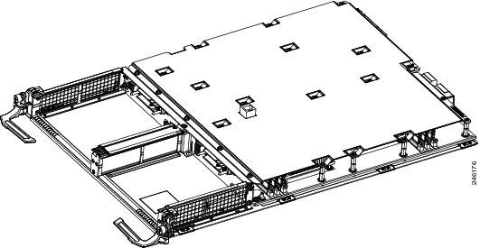
The ISM (Integrated Service Module) line card provides two bays for installation of SAM modules.
Each SAM module has four LEDs visible on their front panels. These four LED indicates the status of the associated SAM, as described in Table 1-4 through Table 1-7.
An example of the ISM (Integrated Service Module) line card is shown in Figure 1-1Figure 1-1.
Figure 1-1 ISM (Integrated Service Module) Line Card
SAM (Service Acceleration Module) Description
The Flash Service Acceleration Module (SAM) provides a solid-state based solution for the video cache requirements of the ISM video solution. Each Flash Module provides two terabytes (2 TB) of memory. From this two terabytes, 1.6 terabytes are available as video caching capacity. The remainder is used for wear level of the flash drives. There is a maximum of two SAMs per ISM, thus, the maximum amount of ISM video cache is 3.2 TB cache per ISM slot.

Note The Flash Service Acceleration Module (SAM) is not needed for the ISM (Integrated Service Module)-based CGv6 applications.
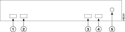
There are four LEDs on each Flash Service Acceleration Module (SAM). 2 to the right and 2 to the left. The SAM Status LED and the SAM Attention LED are to the right side of the SAM. The SAM Status LED is to the rightmost and one before that is the SAM Attention LED. The other two LEDs are located to the Left side of SAM. The leftmost is the Flash Module Fault LED and one next to it is Flash Module Active LED. Refer to Figure 1-3.
The display states and display meanings of the SAM Status LED are described in Table 1-4.
The display states and display meanings of the SAM Attention LED are described in Table 1-5.
The display states and display meanings of the SAM Flash Module Fault LED are described in Table 1-6.
The display states and display meanings of the SAM Flash Module Active LED are described in Table 1-7.
An example of the SAM (Service Acceleration Module) line card is shown in Figure 1-1Figure 1-2.
Figure 1-2 Flashback Service Acceleration Module (SAM) Line Card

Figure 1-3 Flashback Service Acceleration Module (SAM) Line Card Faceplate
SAM LEDs
The SAM Status LED is a dual color LED, displaying either Green or Amber while the SAM is powered up.
The SAM Attention LED is a single red LED.
The SAM Flash Module Fault LED is a a single red LED.
Indicates that the SAM is powered off or that no flash module fault is present. |
|
Indicates that the SAM has one or more flash module faults present. |
The SAM Flash Module Active LED is a single green LED.
SAM Shutdown Button
The Shutdown Button is recessed to avoid being pressed inadvertently.
When the Shutdown Button is pressed the following processes occur:
Step 1![]() The SAM shutdown process starts.The Status LED changes from green to amber.
The SAM shutdown process starts.The Status LED changes from green to amber.
Step 2![]() The software begins removing drivers from the system. The Status LED remains amber.
The software begins removing drivers from the system. The Status LED remains amber.
Step 3![]() Once the software removes the drivers from the system, the SAM will be powered off.
Once the software removes the drivers from the system, the SAM will be powered off.
Step 4![]() When the Status LED changes from amber to off, indicating that the SAM is fully powered off, the SAM can be safely removed.
When the Status LED changes from amber to off, indicating that the SAM is fully powered off, the SAM can be safely removed.
Note It is mandatory to shut down the SAMs before each SAM is removed physically. If not, the ISM line card must be reloaded to recover from any errors that are seen.
Step 5![]() If the ISM line card must be reloaded to recover from any errors, complete Steps 6 and 7 before physically removing each SAM from the ISM.
If the ISM line card must be reloaded to recover from any errors, complete Steps 6 and 7 before physically removing each SAM from the ISM.
Step 6![]() To reload the ISM, either remove and then physically reinsert it or, if you haven’t removed the ISM, execute the
hw-module location 0/1/CPU0 service stop
command in admin mode to stop service on ISM LC's before a soft reload or shutdown or power disable or manual online inservice removal of linecard is performed. This command is supported only for ISM linecards.
To reload the ISM, either remove and then physically reinsert it or, if you haven’t removed the ISM, execute the
hw-module location 0/1/CPU0 service stop
command in admin mode to stop service on ISM LC's before a soft reload or shutdown or power disable or manual online inservice removal of linecard is performed. This command is supported only for ISM linecards.
Executing the hw-module location 0/1/CPU0 service stop command in admin mode ensures that services are taken offline gracefully before the card can be reloaded/removed.
Note This command needs to be used after graceful migration of traffic. Executing the hw-module location 0/1/CPU0 service stop command in admin mode does not ensure graceful migration of traffic. Please refer application specific manual for graceful migration of traffic.
Step 7![]() Execute the
hw-module location 0/1/CPU0 service stop
command in admin mode to take any active services offline gracefully before the ISM card is reloaded/removed.
Execute the
hw-module location 0/1/CPU0 service stop
command in admin mode to take any active services offline gracefully before the ISM card is reloaded/removed.
Step 8![]() To reload the ISM, either remove and then physically reinsert it or, if you haven’t removed the ISM, execute the
hw-module location reload
command in admin mode to perform a soft reinsert.
To reload the ISM, either remove and then physically reinsert it or, if you haven’t removed the ISM, execute the
hw-module location reload
command in admin mode to perform a soft reinsert.
The syntax is hw-module location 0/ x /CPU0 reload or hw-module location 0/ x /CPU1 reload , where x is the slot number.
Here is the example output from executing the hw-module location 0/1/CPU0 reload command:
Step 9![]() Once the ISM has reloaded, you can reload the SAM.
Once the ISM has reloaded, you can reload the SAM.
Step 10![]() To reload the SAM, either physically reinsert it or, if you haven’t removed the SAM, execute the
hw-module location reload
command in admin mode to perform a soft reinsert.
To reload the SAM, either physically reinsert it or, if you haven’t removed the SAM, execute the
hw-module location reload
command in admin mode to perform a soft reinsert.
The syntax is hw-module location 0/ x /SAM0 reload or hw-module location 0/ x /SAM1 reload , where x is the slot number.
Preparing for Installation
The following sections provide information about preparing to install line cards:
Safety Guidelines
Before you perform any procedure in this publication, review the safety guidelines in this section to avoid injuring yourself or damaging the equipment.
The following guidelines are for your safety and to protect equipment. The guidelines do not include all hazards. Be alert.
Note Before installing, configuring, or maintaining a line card, review the safety warnings listed in the Cisco ASR 9000 Series Aggregation Services Router Regulatory Compliance and Safety Information publication that accompanied your router.
- Keep the work area clear and dust free during and after installation. Do not allow dirt or debris to enter into any laser-based components.
- Do not wear loose clothing, jewelry, or other items that could get caught in the router while working with line cards.
- Cisco equipment operates safely when it is used in accordance with its specifications and product usage instructions.

Preventing Electrostatic Discharge
Electrostatic discharge (ESD) damage, which can occur when electronic cards or components are improperly handled, results in complete or intermittent failures. Electromagnetic interference (EMI) shielding is an integral component of the line card. Cisco recommends using an ESD-preventive strap whenever you are handling network equipment or one of its components.
The following are guidelines for preventing ESD damage:
- Always use an ESD-preventive wrist or ankle strap and ensure that it makes good skin contact. Connect the equipment end of the connection cord to an ESD connection socket on the router or to bare metal on the chassis.
- Avoid touching card circuit boards or connector pins. When sliding cards in or out of slots, you should handle them only by the faceplate or metal card carrier.
- When carrying a card, carry it only by the metal card carrier or inside a static shielding bag.
- Place removed line cards component-side-up on an antistatic surface or in a static shielding bag. If you plan to return the component to the factory, immediately place it in a static shielding bag.
- Avoid contact between the line cards and clothing. The wrist strap only protects the board from ESD voltages on the body; ESD voltages on clothing can still cause damage.
Required Tools and Equipment
You need the following tools and parts to remove and install line cards:
- Flat-blade or Phillips screwdriver
- ESD-preventive wrist or ankle strap and instructions
- Interface cables to connect the line card with another router or switch
- Any SFP/XFP modules you need to install (and are not already installed)
Note If you need additional equipment, see Cisco.com or your service representative for ordering information.
Refer to the individual line card descriptions in the “ISM (Integrated Service Module) Line Card Product Overview” section for more information. Table 1-3 summarized the hardware version requirements for each line card.
Removing and Installing a Line Card
The following sections provide procedures for removing or installing a line card:
Note See the “Guidelines for Line Card Removal and Installation” section before removing a line card while power to the router is on.
Guidelines for Line Card Removal and Installation
Guidelines for line card removal and installation include the following:
- Online insertion and removal (OIR) is supported, enabling you to remove and install line cards while the router is operating. OIR is seamless to users on the network, maintains all routing information, and ensures session preservation.
After removing and inserting a line card into the same slot, allow at least 60 seconds before removing or inserting another line card.
- Line cards have two ejector levers to release the card from its backplane connector. Use the levers when you are removing the line card and to seat the line card firmly in its backplane connector when you are installing the line card. The ejector levers align and seat the card connectors in the backplane.
When you install a line card, always use the ejector levers to ensure that the card is correctly aligned with the backplane connector; the connector pins should make contact with the backplane in the correct order, indicating that the card is fully seated in the backplane. If a card is only partially seated in the backplane, the router will hang and subsequently crash.
For line card configuration information, see the “Verifying and Troubleshooting ISM Line Card and SAM Installation” section.
Removing a Line Card
If you are replacing a failed line card, remove the existing line card first, then install the new line card in the same slot. To remove a line card, use Figure 1-4 or Figure 1-5 as a reference and follow these steps:
Step 1![]() Attach an ESD-preventive wrist or ankle strap and follow its instructions for use.
Attach an ESD-preventive wrist or ankle strap and follow its instructions for use.
Step 2![]() Disconnect and remove all interface cables from the ports; note the current connections of the cables to the ports on the line card.
Disconnect and remove all interface cables from the ports; note the current connections of the cables to the ports on the line card.
Step 3![]() Detach the line card cable-management bracket from the line card.
Detach the line card cable-management bracket from the line card.
Step 4![]() Use a screwdriver to loosen the captive screw at each end of the line card faceplate (see Figure 1-4a or Figure 1-5a).
Use a screwdriver to loosen the captive screw at each end of the line card faceplate (see Figure 1-4a or Figure 1-5a).
Figure 1-4 Line Card Removal and Installation for the Cisco ASR 9010 Router
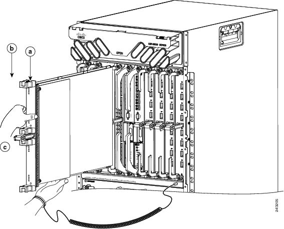
Figure 1-5 Line Card Removal and Installation for the Cisco ASR 9006 Router
Step 5![]() Simultaneously pivot the ejector levers away from each other to release the line card from the backplane connector (see Figure 1-4b or Figure 1-5b).
Simultaneously pivot the ejector levers away from each other to release the line card from the backplane connector (see Figure 1-4b or Figure 1-5b).
Step 6![]() Grasp the ejector levers and pull the line card halfway out of the slot.
Grasp the ejector levers and pull the line card halfway out of the slot.
Step 7![]() Grasp the line card and gently pull it straight out of the slot, keeping your other hand under the line card to guide it (see Figure 1-4c or Figure 1-5c). Avoid touching the line card printed circuit board, components, or any connector pins.
Grasp the line card and gently pull it straight out of the slot, keeping your other hand under the line card to guide it (see Figure 1-4c or Figure 1-5c). Avoid touching the line card printed circuit board, components, or any connector pins.
Step 8![]() Place the removed line card on an antistatic mat, or immediately place it in an antistatic bag if you plan to return it to the factory.
Place the removed line card on an antistatic mat, or immediately place it in an antistatic bag if you plan to return it to the factory.
Step 9![]() If the line card slot is to remain empty, install a line card blank (Product Number A9K-LC-FILR) to keep dust out of the chassis and to maintain proper airflow through the line card compartment. Secure the line card blank to the chassis by tightening its captive screws.
If the line card slot is to remain empty, install a line card blank (Product Number A9K-LC-FILR) to keep dust out of the chassis and to maintain proper airflow through the line card compartment. Secure the line card blank to the chassis by tightening its captive screws.
Note Always insert a dust plug in an optical port opening for each port that is not in use.
Installing a Line Card
A line card slides into almost any available line card slot and connects directly to the backplane. If you install a new line card, you must first remove the line card blank from the available slot.
Note Refer to the installation and configuration guide for your router for information on line card slot types, slot width, and slot location.
To install a line card, follow these steps:
Step 1![]() Attach an ESD-preventive wrist or ankle strap and follow its instructions for use.
Attach an ESD-preventive wrist or ankle strap and follow its instructions for use.
Step 2![]() Choose an available line card slot for the line card, and verify that the line card interface cable is long enough for you to connect the line card with any external equipment.
Choose an available line card slot for the line card, and verify that the line card interface cable is long enough for you to connect the line card with any external equipment.
Step 3![]() Grasp the faceplate of the line card with one hand and place your other hand under the metal card carrier to support the weight of the card (see Figure 1-4 or Figure 1-5). Position the card for insertion into the card cage slot. Avoid touching the line card printed circuit board, components, or any connector pins.
Grasp the faceplate of the line card with one hand and place your other hand under the metal card carrier to support the weight of the card (see Figure 1-4 or Figure 1-5). Position the card for insertion into the card cage slot. Avoid touching the line card printed circuit board, components, or any connector pins.
Step 4![]() Carefully slide the line card into the slot until the ejector levers make contact with the edges of the card cage, then
stop
when the ejector lever hooks catch the lip of the card cage. If they do not catch, try reinserting the line card until the ejector levers are fully latched.
Carefully slide the line card into the slot until the ejector levers make contact with the edges of the card cage, then
stop
when the ejector lever hooks catch the lip of the card cage. If they do not catch, try reinserting the line card until the ejector levers are fully latched.
Step 5![]() Simultaneously pivot both ejector levers toward each other until they are perpendicular to the line card faceplate. This action firmly seats the card in the backplane.
Simultaneously pivot both ejector levers toward each other until they are perpendicular to the line card faceplate. This action firmly seats the card in the backplane.
Step 6![]() Tighten the captive screw on each end of the line card faceplate to ensure proper EMI shielding and to prevent the line card from becoming partially dislodged from the backplane. Tighten the captive screws to a torque of 10 +/–1 in-lb.
Tighten the captive screw on each end of the line card faceplate to ensure proper EMI shielding and to prevent the line card from becoming partially dislodged from the backplane. Tighten the captive screws to a torque of 10 +/–1 in-lb.
For information on verifying and troubleshooting the hardware installation, see the “Verifying and Troubleshooting ISM Line Card and SAM Installation” section.
ISM (Integrated Service Module) Line Cards
This section describes how to install or remove ISM (Integrated Service Module) line cards on
Cisco ASR 9000 Series Aggregation Services Routers. This chapter contains the following sections:
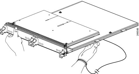
Handling ISM (Integrated Service Module) Line Cards
Each ISM (Integrated Service Module) line card circuit board is mounted to a metal carrier and is sensitive to electrostatic discharge (ESD) damage. Before you begin installation, read “Preparing to Install a SAM (Service Acceleration Module) or an ISM (Integrated Service Module) Line Card” for a list of parts and tools required for installation.
When a slot is not in use, a blank must fill the empty slot to allow the router to conform to electromagnetic interference (EMI) emissions requirements and to allow proper airflow across the installed modules. If you plan to install an ISM (Integrated Service Module) line card in a slot that is not in use, you must first remove the blank.
Figure 1-6 Handling an ISM (Integrated Service Module) Line Card
Removing and Installing an ISM (Integrated Service Module) Line Card
The following sections describe the procedures for removing and installing ISM (Integrated Service Module) line cards:
- Guidelines for ISM (Integrated Service Module) Line Card Removal and Installation
- Removing a Line Card
- Installing an ISM (Integrated Service Module) Line Card
Note Some of the procedures in the following sections use illustrations of a 10-slot Cisco ASR 9000 Series Router to support the descriptions of removing and installing ISM (Integrated Service Module) line cards. Although the card cages of Cisco ASR-9000 Series Routers differ (vertical slot orientation for the 10-slot Cisco ASR 9000 Series Router, horizontal slot orientation for the 6-slot Cisco ASR 9000 Series Router), the designated use of slots and the process of installing and removing an ISM (Integrated Service Module) line card are basically the same. Therefore, separate procedures and illustrations are not included in this publication.
Guidelines for ISM (Integrated Service Module) Line Card Removal and Installation
Guidelines for ISM (Integrated Service Module) line card removal and installation include the following:
- Online insertion and removal (OIR) is supported, enabling you to remove and install ISM (Integrated Service Module) line cards while the router is operating.
Note With OIR, notifying the software or resetting the power is not required. However, you have the option of using the hw-module loc rack/slot/CPU0 maint command before removing an ISM (Integrated Service Module) line card.
Note To avoid solid state disk failures, it is mandatory to shutdown the ISM (Integrated Service Module) line card before OIR.
- After you reinstall an ISM (Integrated Service Module) line card, the router automatically downloads the necessary software from the Route Switch Processor (RSP).
- ISM (Integrated Service Module) line cards have two ejector levers to release the card from its backplane connector. Use the levers when you are removing the ISM (Integrated Service Module) line card and to seat the ISM (Integrated Service Module) line card firmly in its backplane connector when you are installing the ISM (Integrated Service Module) line card. The ejector levers align and seat the card connectors in the backplane.
When you install an ISM (Integrated Service Module) line card, always use the ejector levers to ensure that the card is correctly aligned with the backplane connector; the connector pins should make contact with the backplane in the correct order, indicating that the card is fully seated in the backplane. A card that is only partially seated in the backplane will cause the router to hang and subsequently crash.
Removing an ISM (Integrated Service Module) Line Card
If you are replacing a failed ISM (Integrated Service Module) line card, remove the existing ISM (Integrated Service Module) line card first, then install the new ISM (Integrated Service Module) line card in the same slot. To remove an ISM (Integrated Service Module) line card, use Figure 1-4 as a reference and follow these steps:
Step 1![]() Attach an ESD-preventive wrist strap and follow its instructions for use.
Attach an ESD-preventive wrist strap and follow its instructions for use.
Step 2![]() Use a screwdriver to loosen the captive screw at each end of the ISM (Integrated Service Module) line card faceplate. (See Figure 1-8.)
Use a screwdriver to loosen the captive screw at each end of the ISM (Integrated Service Module) line card faceplate. (See Figure 1-8.)
Figure 1-7 ISM (Integrated Service Module) Line Card Removal and Installation
Step 3![]() Simultaneously pivot the ejector levers away from each other to release the ISM (Integrated Service Module) line card from the backplane connector. (See Figure 1-8.)
Simultaneously pivot the ejector levers away from each other to release the ISM (Integrated Service Module) line card from the backplane connector. (See Figure 1-8.)
Step 4![]() Grasp the ejector levers and pull the ISM (Integrated Service Module) line card halfway out of the slot.
Grasp the ejector levers and pull the ISM (Integrated Service Module) line card halfway out of the slot.
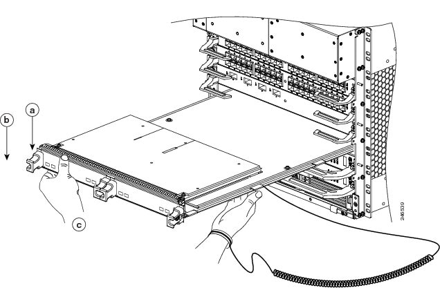
Step 5![]() Grasp the ISM (Integrated Service Module) line card and gently pull it straight out of the slot, keeping your other hand under the ISM (Integrated Service Module) line card to guide it. (See Figure 1-7.) Avoid touching the ISM (Integrated Service Module) line card printed circuit board, components, or any connector pins.
Grasp the ISM (Integrated Service Module) line card and gently pull it straight out of the slot, keeping your other hand under the ISM (Integrated Service Module) line card to guide it. (See Figure 1-7.) Avoid touching the ISM (Integrated Service Module) line card printed circuit board, components, or any connector pins.
Step 6![]() Place the removed ISM (Integrated Service Module) line card on an antistatic mat, or immediately place it in an antistatic bag if you plan to return it to the factory.
Place the removed ISM (Integrated Service Module) line card on an antistatic mat, or immediately place it in an antistatic bag if you plan to return it to the factory.
Step 7![]() If the ISM (Integrated Service Module) line card slot is to remain empty, install a line card blank to keep dust out of the chassis and to maintain proper airflow through the ISM (Integrated Service Module) line card compartment. Secure the line card blank to the chassis by tightening its captive screws.
If the ISM (Integrated Service Module) line card slot is to remain empty, install a line card blank to keep dust out of the chassis and to maintain proper airflow through the ISM (Integrated Service Module) line card compartment. Secure the line card blank to the chassis by tightening its captive screws.
Installing an ISM (Integrated Service Module) Line Card
An ISM (Integrated Service Module) line card slides into any available line card slot and connects directly to the backplane. If you install a new ISM (Integrated Service Module) line card, you must first remove the line card blank from the available slot.
Note Refer to Figure 2-6 Cisco ASR 9010 Router Components and Slot Numbering and Figure 2-7 Cisco ASR 9006 Router Components and Slot Numbering in the Unpacking and Installing the Chassis chapter of the Cisco ASR 9000 Series Aggregation Services Router Hardware Installation Guide for information on line card slot types in order to determine an appropriate slot in which to install the ISM (Integrated Service Module) line card.
To install an ISM (Integrated Service Module) line card, follow these steps:
Step 1![]() Attach an ESD-preventive wrist or ankle strap and follow its instructions for use.
Attach an ESD-preventive wrist or ankle strap and follow its instructions for use.
Step 2![]() Choose an available ISM (Integrated Service Module) line card slot for the ISM (Integrated Service Module) line card.
Choose an available ISM (Integrated Service Module) line card slot for the ISM (Integrated Service Module) line card.
Step 3![]() Grasp the handle of the ISM (Integrated Service Module) line card with one hand and place your other hand under the card carrier to support the weight of the card; position the card for insertion into the card cage slot. Avoid touching the ISM (Integrated Service Module) line card printed circuit board, components, or any connector pins.
Grasp the handle of the ISM (Integrated Service Module) line card with one hand and place your other hand under the card carrier to support the weight of the card; position the card for insertion into the card cage slot. Avoid touching the ISM (Integrated Service Module) line card printed circuit board, components, or any connector pins.
Step 4![]() Carefully slide the ISM (Integrated Service Module) line card into the slot until the ejector levers make contact with the edges of the card cage, then
stop
when the ejector lever hooks catch the lip of the card cage. If they do not catch, try reinserting the ISM (Integrated Service Module) line card until the ejector lever hooks are fully latched. (See Figure 1-8.)
Carefully slide the ISM (Integrated Service Module) line card into the slot until the ejector levers make contact with the edges of the card cage, then
stop
when the ejector lever hooks catch the lip of the card cage. If they do not catch, try reinserting the ISM (Integrated Service Module) line card until the ejector lever hooks are fully latched. (See Figure 1-8.)
Figure 1-8 ISM (Integrated Service Module) Card Ejector Lever Positions During Installation

|
Note: Vertical red lines in Figure 1-8 indicate a line fully parallel to the ISM (Integrated Service Module) card front panel. |
|||||
Slightly loose position of ejector levers when the ISM (Integrated Service Module) card is fully seated in the backplane, but the captive installation screws are not fully tightened |
Fully parallel position of ejector levers when the ISM (Integrated Service Module) card is fully seated in the backplane and captive installation screws are fully tightened |
Slight gap that may be present when the ISM (Integrated Service Module) card is fully seated in the backplane and captive installation screws are fully tightened |
|||
Step 5![]() Simultaneously pivot both ejector levers toward each other until they are perpendicular to the ISM (Integrated Service Module) line card faceplate. This action firmly seats the card in the backplane.
Simultaneously pivot both ejector levers toward each other until they are perpendicular to the ISM (Integrated Service Module) line card faceplate. This action firmly seats the card in the backplane.
Step 6![]() Use a 3/16-inch flat-blade screwdriver to tighten the captive screw on each end of the ISM (Integrated Service Module) line card faceplate to ensure proper EMI shielding and to prevent the ISM (Integrated Service Module) line card from becoming partially dislodged from the backplane. Tighten the locking thumbscrews on both sides of the ISM (Integrated Service Module) line card to a torque of between 8.3 and 11 inch-pounds (94 to 124 N-cm). Do not overtighten.
Use a 3/16-inch flat-blade screwdriver to tighten the captive screw on each end of the ISM (Integrated Service Module) line card faceplate to ensure proper EMI shielding and to prevent the ISM (Integrated Service Module) line card from becoming partially dislodged from the backplane. Tighten the locking thumbscrews on both sides of the ISM (Integrated Service Module) line card to a torque of between 8.3 and 11 inch-pounds (94 to 124 N-cm). Do not overtighten.
Step 7![]() Install the SAMs (Service Acceleration Modules) into each newly installed ISM (Integrated Service Module) line card.
Install the SAMs (Service Acceleration Modules) into each newly installed ISM (Integrated Service Module) line card.
Note The Flash Service Acceleration Module (SAM) is not needed for the ISM (Integrated Service Module)-based CGv6 applications. If you are running ISM (Integrated Service Module)-based CGv6 applications, go to the “Checking the Installation” section below.
SAMs (Service Acceleration Modules)
This section describes how to install or remove SAMs (Service Acceleration Modules) on the Cisco ASR-9000 Series Router. This section contains the following procedures:
- Handling SAMs (Service Acceleration Modules)
- Online Insertion and Removal
- SAM (Service Acceleration Module) Installation and Removal
- Checking the Installation
Note The Flash Service Acceleration Module (SAM) is not needed for the ISM (Integrated Service Module)-based CGv6 applications. If you are running ISM (Integrated Service Module)-based CGv6 applications, go to the “Checking the Installation” below.
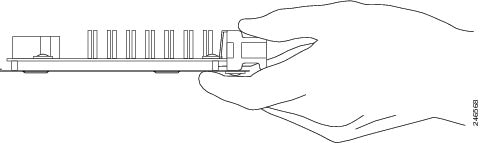
Handling SAMs (Service Acceleration Modules)
Each SAM (Service Acceleration Module) circuit board is mounted to a metal carrier and is sensitive to electrostatic discharge (ESD) damage. Before you begin installation, read “Preparing to Install a SAM (Service Acceleration Module) or an ISM (Integrated Service Module) Line Card” for a list of parts and tools required for installation.
When a bay is not in use, a blank must fill the empty bay to allow the router or switch to conform to electromagnetic interference (EMI) emissions requirements and to allow proper airflow across the installed modules. If you plan to install a SAM (Service Acceleration Module) in a bay that is not in use, you must first remove the blank.
Figure 1-9 Handling a SAM (Service Acceleration Module)
Online Insertion and Removal
Cisco ASR 9000 Series Router ISM (Integrated Service Module) line cards and SAMs (Service Acceleration Modules) support online insertion and removal (OIR). SAMs (Service Acceleration Modules) can be inserted or removed independently from the ISM (Integrated Service Module) line card. OIR of a ISM (Integrated Service Module) line card with installed SAMs (Service Acceleration Modules) is also supported.
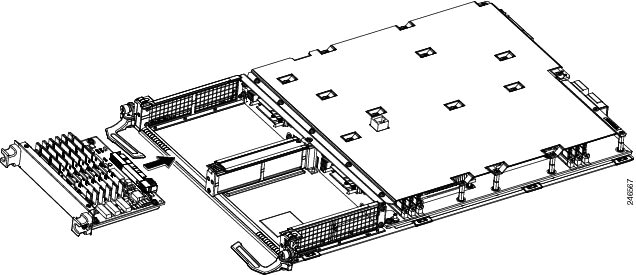
SAM (Service Acceleration Module) Installation and Removal
This section provides step-by-step instructions for removing and installing a SAM (Service Acceleration Module) in an ISM (Integrated Service Module) line card.
To remove and install a SAM (Service Acceleration Module) in an ISM (Integrated Service Module) line card, refer to Figure 1-10 and do the following:
Step 1![]() To insert the SAM (Service Acceleration Module) in the ISM (Integrated Service Module) line card, locate the guide rails inside the ISM (Integrated Service Module) line card that hold the SAM (Service Acceleration Module) in place. They are at the top and bottom of the SAM (Service Acceleration Module) slot and are recessed about an inch, as shown in C of Figure 1-10.
To insert the SAM (Service Acceleration Module) in the ISM (Integrated Service Module) line card, locate the guide rails inside the ISM (Integrated Service Module) line card that hold the SAM (Service Acceleration Module) in place. They are at the top and bottom of the SAM (Service Acceleration Module) slot and are recessed about an inch, as shown in C of Figure 1-10.
Step 2![]() Carefully slide the SAM (Service Acceleration Module) all the way in the ISM (Integrated Service Module) line card until the SAM (Service Acceleration Module) is firmly seated in the SAM (Service Acceleration Module) interface connector. When fully seated, the SAM (Service Acceleration Module) might be slightly behind the ISM (Integrated Service Module) line card faceplate.
Carefully slide the SAM (Service Acceleration Module) all the way in the ISM (Integrated Service Module) line card until the SAM (Service Acceleration Module) is firmly seated in the SAM (Service Acceleration Module) interface connector. When fully seated, the SAM (Service Acceleration Module) might be slightly behind the ISM (Integrated Service Module) line card faceplate.
Note The SAM (Service Acceleration Module) will slide easily into the slot if it is properly aligned on the tracks. If the SAM (Service Acceleration Module) does not slide easily, do NOT force it. Remove the SAM (Service Acceleration Module) and reposition it, paying close attention to engaging it on the tracks.
Step 3![]() To remove the SAM (Service Acceleration Module) from the ISM (Integrated Service Module) line card, first press the recessed Shutdown Button, then wait for the LEDs to go off (normally 10 seconds but up to 2 minutes).
To remove the SAM (Service Acceleration Module) from the ISM (Integrated Service Module) line card, first press the recessed Shutdown Button, then wait for the LEDs to go off (normally 10 seconds but up to 2 minutes).
Step 4![]() Grasp the SAM (Service Acceleration Module) and pull the SAM (Service Acceleration Module) from the ISM (Integrated Service Module) line card.
Grasp the SAM (Service Acceleration Module) and pull the SAM (Service Acceleration Module) from the ISM (Integrated Service Module) line card.
Figure 1-10 SAM (Service Acceleration Module) Installation and Removal
Checking the Installation
This section describes the procedures you can use to verify the ISM (Integrated Service Module) line card and SAM (Service Acceleration Module) installation, and includes information on the following topics:
- Verifying the Installation
- Using show Commands to Verify ISM (Integrated Service Module) Line Card and SAM (Service Acceleration Module) Status
- Using show Commands to Display SAM (Service Acceleration Module) Information
Verifying the Installation
This section describes how to verify the ISM (Integrated Service Module) line card and SAM (Service Acceleration Module) installation by observing the SAM (Service Acceleration Module) LED states.
When the system has re initialized, the ISM (Integrated Service Module) line card status is confirmed through observation of the four SAM (Service Acceleration Module) LEDs. The SAM Status LED should be green (on). The SAM Attention LED should be off. A red SAM Attention LED indicates that there is a SAM error and that the SAM needs attention. If the SAM Attention LED is flashing red, that indicates that someone has pressed the Shutdown Button.If the SAM Flash Module Fault LED is red, that indicates that the SAM has one or more flash module faults present. The SAM Flash Module Active LED on the Service Acceleration Modules (SAMs) front panel should be green. No light indicates that the SAM is powered off or that there are no activities on flash module and ASIC. If the SAM Flash Module Active LED is flashing green, that indicates that the SAM is in the process of powering up and/or that activity is occuring on the SAM flash module and ASIC. The SAM Flash Module Active LED should eventually transition from flashing green to solid green, indicating that the SAM is powered up and that the SAM flash module and ASIC are active.
Use the following procedure to verify that a ISM (Integrated Service Module) line card and SAM (Service Acceleration Module) are installed correctly:
Step 1![]() Observe the console display messages and verify that the system discovers the ISM (Integrated Service Module) line card, while the system re initializes, as follows:
Observe the console display messages and verify that the system discovers the ISM (Integrated Service Module) line card, while the system re initializes, as follows:
- As an ISM (Integrated Service Module) line card and the Service Acceleration Modules (SAMs) are initialized, the SAM Status LED will first be amber, indicating that power is on, but the ISM (Integrated Service Module) line card and the Service Acceleration Modules (SAMs) are both being configured. When the ISM (Integrated Service Module) line card and the Service Acceleration Modules (SAMs) are both active, the SAM Status LED will illuminate green.
- SAMs (Service Acceleration Modules) will follow the same sequence after the ISM (Integrated Service Module) line card has completed its initialization. The SAM (Service Acceleration Module) STATUS LEDs will illuminate amber, turning to green when the SAMs (Service Acceleration Modules) become active.
Step 2![]() If the ISM (Integrated Service Module) line cards and SAMs (Service Acceleration Modules) have not become active within three minutes, refer to the system console messages. If there is no indication that a field-programmable device (FPD) upgrade is underway, see Chapter2, “Verifying and Troubleshooting the Line Card Installation”
If the ISM (Integrated Service Module) line cards and SAMs (Service Acceleration Modules) have not become active within three minutes, refer to the system console messages. If there is no indication that a field-programmable device (FPD) upgrade is underway, see Chapter2, “Verifying and Troubleshooting the Line Card Installation”
Using show Commands to Verify ISM (Integrated Service Module) Line Card and SAM (Service Acceleration Module) Status
The following procedure uses show commands to verify that the new SAMs (Service Acceleration Modules) are installed correctly and operating correctly.
Step 1![]() Use the
show running-config
command to display the system
Use the
show running-config
command to display the system![]() configuration.
configuration.
Step 2![]() Display information about the installed ISM (Integrated Service Module) line cards using the
show diag
command.
Display information about the installed ISM (Integrated Service Module) line cards using the
show diag
command.
Step 3![]() Use the
show hw-module fpd
location
<rack/slot/subslot>
command to verify the FPD version information of the SAMs (Service Acceleration Modules) installed in the system
Use the
show hw-module fpd
location
<rack/slot/subslot>
command to verify the FPD version information of the SAMs (Service Acceleration Modules) installed in the system![]() . The
hw-module fpd
location
<rack/slot/subslot>
command can be used for upgrading the FPD version on the installed ISM (Integrated Service Module) line cards and/or the SAMs (Service Acceleration Modules).
. The
hw-module fpd
location
<rack/slot/subslot>
command can be used for upgrading the FPD version on the installed ISM (Integrated Service Module) line cards and/or the SAMs (Service Acceleration Modules).
Note If a SAM (Service Acceleration Module) does not meet the minimum version required, the FPD may need to be updated. Refer to Cisco ASR 9000 Series Aggregation Services Router System Management Configuration Guide for instructions. If the update fails, the failing module is powered down and an error message displays on the system console.
Step 4![]() Use the
show platform
command to check the state of all the boards in the chassis, including the ISM (Integrated Service Module) line card and the SAMs (Service Acceleration Modules).
Use the
show platform
command to check the state of all the boards in the chassis, including the ISM (Integrated Service Module) line card and the SAMs (Service Acceleration Modules).
The SAM (Service Acceleration Module) state should be “OK” and the ISM (Integrated Service Module) line card state should be “IOS XR RUN” in the show platform command output. The CPU1 status should be “SEOS-READY”.
Step 5![]() Finally, you can use the
show version
command to obtain software version information for the installed ISM (Integrated Service Module) line cards. The
show platform summary location 0/1/CPU0
command provides the application software version that is running on this board.
Finally, you can use the
show version
command to obtain software version information for the installed ISM (Integrated Service Module) line cards. The
show platform summary location 0/1/CPU0
command provides the application software version that is running on this board.
Using show Commands to Display SAM (Service Acceleration Module) Information
Table 1-8 describes the show commands you can use to display SAM (Service Acceleration Module) information.
SAM (Service Acceleration Module) type in that slot, hardware revision, part number, and EEPROM contents. |
||
The following sample display shows the events logged by the system as you insert a new ISM (Integrated Service Module) line card in module slot 0.
Use the following procedure to verify that the ISM (Integrated Service Module) line card is installed correctly:
Step 1![]() Observe the console display messages and verify that the system discovers the ISM (Integrated Service Module) line card.
Observe the console display messages and verify that the system discovers the ISM (Integrated Service Module) line card.
Step 2![]() Verify that the STATUS LED on the SAM (Service Acceleration Module) goes on (is green) and remains on after the reinstallation is complete. If the STATUS LED remains on, proceed to Step 5. If the STATUS LED does not remain on, proceed to Step 3.
Verify that the STATUS LED on the SAM (Service Acceleration Module) goes on (is green) and remains on after the reinstallation is complete. If the STATUS LED remains on, proceed to Step 5. If the STATUS LED does not remain on, proceed to Step 3.
Step 3![]() If the STATUS LED on a SAM (Service Acceleration Module) fails to go on, the SAM (Service Acceleration Module) or the ISM (Integrated Service Module) line card might not be fully seated.
If the STATUS LED on a SAM (Service Acceleration Module) fails to go on, the SAM (Service Acceleration Module) or the ISM (Integrated Service Module) line card might not be fully seated.
- Remove the SAM (Service Acceleration Module) from the ISM (Integrated Service Module) line card.
- Inspect the SAM (Service Acceleration Module). Verify there are no bent pins or parts and that there is nothing lodged in the two devices that could prevent a good connection.
- Insert the SAM (Service Acceleration Module) in the ISM (Integrated Service Module) line card by sliding the SAM (Service Acceleration Module) all the way in the ISM (Integrated Service Module) line card until the SAM (Service Acceleration Module) is firmly seated in the SAM (Service Acceleration Module) interface connector. When fully seated in the ISM (Integrated Service Module) line card, the SAM (Service Acceleration Module) might be slightly behind the ISM (Integrated Service Module) line card faceplate.
Note The SAM (Service Acceleration Module) will slide easily into the slot if it is properly aligned on the tracks. If the SAM (Service Acceleration Module) does not slide easily, do NOT force it. Remove the SAM (Service Acceleration Module) and reposition it, paying close attention to engaging it on the tracks.
- After the system re initialization, the STATUS LED on the SAM (Service Acceleration Module) should go on and remain on. If the STATUS LED remains on, proceed to Step 5. If it does not, try reseating the SAM (Service Acceleration Module) in a different subslot within the ISM (Integrated Service Module) line card.
- If the STATUS LED on a SAM (Service Acceleration Module) fails to go on after reseating the SAM (Service Acceleration Module) in a different subslot within the ISM (Integrated Service Module) line card, proceed to Step 4.
Step 4![]() If the STATUS LED on a SAM (Service Acceleration Module) still fails to go on, remove the SAM (Service Acceleration Module) from the ISM (Integrated Service Module) line card, then remove the ISM (Integrated Service Module) line card and install it in another available slot on the router. Wait for the STATUS LED on the ISM (Integrated Service Module) line card to turn green.
If the STATUS LED on a SAM (Service Acceleration Module) still fails to go on, remove the SAM (Service Acceleration Module) from the ISM (Integrated Service Module) line card, then remove the ISM (Integrated Service Module) line card and install it in another available slot on the router. Wait for the STATUS LED on the ISM (Integrated Service Module) line card to turn green.
- If the STATUS LED goes on, suspect a failed backplane port in the original slot.
- If the STATUS LED fails to go on, remove the ISM (Integrated Service Module) line card and ensure the SAM (Service Acceleration Module) is firmly seated in its slot. Remove and reinstall it accordingly.
- If the STATUS LED still fails to go on, but other LEDs on the SAM (Service Acceleration Module) go on to indicate activity, proceed to Step 5 to resume the installation checkout; suspect that the STATUS LED on the SAM (Service Acceleration Module) or the SAM (Service Acceleration Module) bay has failed. Contact a service representative to report the problem and obtain further instructions.
- If no LEDs on the SAM (Service Acceleration Module) go on:
–![]() Verify that the SAM (Service Acceleration Module) is supported on the ISM (Integrated Service Module) line card and that it has the required hardware revision. If the SAM (Service Acceleration Module) is not supported or has an old hardware revision, the show diag command indicates that the ISM (Integrated Service Module) line card is deactivated.
Verify that the SAM (Service Acceleration Module) is supported on the ISM (Integrated Service Module) line card and that it has the required hardware revision. If the SAM (Service Acceleration Module) is not supported or has an old hardware revision, the show diag command indicates that the ISM (Integrated Service Module) line card is deactivated.
–![]() If there is another ISM (Integrated Service Module) line card available in the router, to test your SAM (Service Acceleration Module) move the SAM (Service Acceleration Module) to the other ISM (Integrated Service Module) line card.
If there is another ISM (Integrated Service Module) line card available in the router, to test your SAM (Service Acceleration Module) move the SAM (Service Acceleration Module) to the other ISM (Integrated Service Module) line card.
–![]() Suspect a faulty ISM (Integrated Service Module) line card. Contact a service representative to report the problem and obtain further instructions.
Suspect a faulty ISM (Integrated Service Module) line card. Contact a service representative to report the problem and obtain further instructions.
Note If you move the SAM (Service Acceleration Module) to a different subslot in the ISM (Integrated Service Module) line card and it works, there are probably issues with the subslot in the ISM (Integrated Service Module) line card. Contact a service representative re: the broken subslot. If you test the SAM (Service Acceleration Module) in another ISM (Integrated Service Module) line card and it works, the original ISM (Integrated Service Module) line card probably has some issues and needs troubleshooting. Contact a service representative to report the problem and obtain further instructions.
Step 5![]() If the SAM (Service Acceleration Module) is new and is not a replacement, configure the new SAM (Service Acceleration Module) using the instructions in
Cisco IOS XR Getting Started Guide for the Cisco ASR 9000 Series Router
and
Cisco ASR 9000 Series Aggregation Services Router Interface and Hardware Component Configuration Guide
.
If the SAM (Service Acceleration Module) is new and is not a replacement, configure the new SAM (Service Acceleration Module) using the instructions in
Cisco IOS XR Getting Started Guide for the Cisco ASR 9000 Series Router
and
Cisco ASR 9000 Series Aggregation Services Router Interface and Hardware Component Configuration Guide
.
Step 6![]() If the ISM (Integrated Service Module) line card is a replacement, use the
show platform
command to verify the status of the SAMs (Service Acceleration Modules). (See the “Using show Commands to Verify ISM (Integrated Service Module) Line Card and SAM (Service Acceleration Module) Status” section.)
If the ISM (Integrated Service Module) line card is a replacement, use the
show platform
command to verify the status of the SAMs (Service Acceleration Modules). (See the “Using show Commands to Verify ISM (Integrated Service Module) Line Card and SAM (Service Acceleration Module) Status” section.)
Step 7![]() Repeat Step 1 through Step 6 to verify that any additional ISM (Integrated Service Module) line cards are properly installed.
Repeat Step 1 through Step 6 to verify that any additional ISM (Integrated Service Module) line cards are properly installed.
If you experience other problems that you are unable to solve, contact TAC (see the “Obtaining Documentation and Submitting a Service Request” section in the Preface) or a service representative for assistance.
To configure the new interface, use Cisco ASR 9000 Series Aggregation Services Router Interface and Hardware Component Configuration Guide .
Note ACL-based-routing on Service-engine interfaces connecting to an ISM (Integrated Service Module) line card is not supported.
Note VRF on Service-engine interfaces connecting to an ISM (Integrated Service Module) line card is not supported.
 Feedback