Subscriber Management

This chapter provides information about various types of subscriber sessions, namely IPoE and PPPoE, and IP addressing by DHCP. Also, on how the point-point frames are tunnelled across the network using the Layer 2 Tunneling Protocol.

Subscriber Session Overview

To enable subscribers to access the network resources, the network has to establish a session with the subscriber. A subscriber session represents the logical connection between the customer premise equipment (CPE) and the network resource. Each session establishment comprises the following phases:

  • Establishing a connection—in this phase CPE finds the cnBNG with which to communicate.

  • Authenticating and authorizing the subscriber—in this phase, cnBNG authenticates the subscribers and authorizes them to use the network. This phase is performed with the help of the RADIUS server.

  • Giving the subscriber an identity—in this phase, the subscriber is assigned an identity, the IP address.

  • Monitoring the session—in this phase, cnBNG ascertains that the session is up and running.

The subscriber sessions are established over the subscriber interfaces, which are virtual interfaces. It's possible to create only one interface for each subscriber session. A port can contain multiple VLANs, each of which can support multiple subscribers. cnBNG creates subscriber interfaces for each kind of session. These interfaces are named based on the parent interface, such as bundle-ether 2.100.pppoe312. The subscribers on bundle interfaces (or bundle-VLANs) allow redundancy and are managed on the cnBNG route processor (RP).

There are two mechanisms to establish a subscriber session, namely, IPoE and PPPoE.
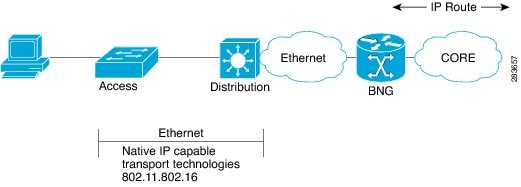
IPoE Session

In an Internet over Ethernet (IPoE) subscriber session, subscribers run IPv4 or IPv6 on the CPE device and connect to the cnBNG through a Layer-2 aggregation. IP subscriber sessions that connect through a Layer-2 aggregation network are called L2-connected. IPoE subscriber sessions are always terminated on cnBNG and then routed into the service provider network. IPoE relies on DHCP to assign the IP address.

Figure 1. IPoE Session


cnBNG supports both DHCP v4 and DHCP v6 subscriber sessions.

Limitations

The following are the limitations:

  • L3 routed subscribers are not supported.

  • Geo redundancy or subscriber redundancy is not supported.

  • Line card or physical port termination-based subscribers are not supported.

Configuration Example

Router#configure
Router(config)#interface Bundle-Ether1.1
Router(config-subif)#ipv4 point-to-point
Router(config-subif)#ipv4 unnumbered Loopback1
Router(config-subif)#ipv6 enable
Router(config-subif)#encapsulation dot1q 1
Router(config-subif)#ipsubscriber
Router(config-cnbng-nal-ipsub)#ipv4 l2-connected
Router(config-cnbng-nal-ipsub-l2conn)#initiator dhcp
Router(config-cnbng-nal-ipsub-l2conn)#exit
Router(config-cnbng-nal-ipsub)#ipv6 l2-connected
Router(config-cnbng-nal-ipsub-ipv6-l2conn)#initiator dhcp
Router(config-cnbng-nal-ipsub-ipv6-l2conn)#commit

Running Configuration


Router#show running-config interface be1.1
interface Bundle-Ether1.1
 ipv4 point-to-point
 ipv4 unnumbered Loopback1
 ipv6 enable
 encapsulation dot1q 1
 ipsubscriber
  ipv4 l2-connected
   initiator dhcp
  !
  ipv6 l2-connected
   initiator dhcp
  !
 !

PPP over Ethernet (PPPoE)

The Point-to-Point Protocol (PPP) is used for communications between two nodes, like a client and a server. The PPP provides a standard method for transporting multiprotocol datagrams over point-to-point links. It defines an encapsulation scheme, a link layer control protocol (LCP), and a set of network control protocols (NCPs) for different network protocols that can be transmitted over the PPP link.

One of the methods to establish PPP connection is by the use of PPPoE. In a PPPoE session, the PPP protocol runs between the CPE and cnBNG. The Home Gateway (which is part of the CPE) adds a PPP header (encapsulation) that is terminated at the cnBNG.

PPPoE Discovery

The PPPoE discovery-stage protocol consists of basic packet exchange between the subscriber and server (cnBNG). The following is the list of the various PPPoE Active Discovery (PAD) messages:

  • PPPoE Active Discovery Initiation (PADI)—The CPE broadcasts to initiate the process to discover cnBNG.

  • PPPoE Active Discovery Offer (PADO)—The cnBNG responds with an offer.

  • PPPoE Active Discovery Request (PADR)—The CPE requests to establish a connection.

  • PPPoE Active Discovery Session confirmation (PADS)—cnBNG accepts the request and responds by assigning a session identifier (Session-ID).

  • PPPoE Active Discovery Termination (PADT)—Either CPE or cnBNG terminates the session.

PPoE Sessions

The PPPoE sessions are of the following types:

  • PPPoE PPP Terminated sessions Terminated (PTA)

  • PPPoE L2TP Access Concentrator Sessions (LAC)

  • L2TP Network Server Sessions (LNS)

Majority of the digital subscriber line (DSL) broadband deployments use Point-to-Point Protocol over Ethernet (PPPoE) sessions to provide subscriber services. These sessions terminate the Point-to-Point Protocol (PPP) link and provide all the features, service, and billing on the same node. These sessions are called PPP Terminated (PTA) sessions. See PPPoE PPP Terminated and Aggregation Sessions (PPPoE-PTA).

There are some wireline subscriber deployments in the wholesale retail model where ISPs work with others to provide the access and core services separately. In such cases, the subscribers are tunneled between wholesale and retail ISPs using the Layer 2 Tunneling Protocol (L2TP), a client-server protocol. See L2TP Access Concentrator Sessions (LAC) and L2TP Network Server Sessions (LNS).


Note


For the functioning of PPP PTA and PPP LAC session, the RADIUS server must be set up to authenticate and forward sessions as necessary. There's no local authentication available on cnBNG.


PPPoE PPP Terminated and Aggregation Sessions (PPPoE-PTA)

In a PPPoE-PPP Termination and Aggregation (PTA) session, the PPP encapsulation is terminated on cnBNG. After it’s terminated, cNBNG routes the traffic to the service provider using IP routing. A typical PTA session is depicted in this figure.

Figure 2. PPPoE-PTA Session


PPPoE session configuration information is contained in PPPoE profiles. After a profile is defined, it’s assigned to an access interface. Multiple PPPoE profiles can be created and assigned to multiple interfaces. A global PPPoE profile can also be created; the global profile serves as the default profile for any interface that has not been assigned a specific PPPoE profile.

The PPP PTA session is typically used in the Network Service Provider (retail) model where the same service operator provides the broadband connection to the subscriber and also manages the network services.

Limitations

The following are the limitations:

  • L3 routed subscribers are not supported.

  • Geo redundancy or subscriber redundancy is not supported.

  • Line card or physical port termination-based subscribers aren’t supported.

Configure PPPoE-PTA Session

The following section describes the steps to configure PPPoE-PTA sessions:

  • Configure the access-interface

  • Enable PPPoE

Configuration Example

Router#configure
Router(config)#interface Bundle-Ether1.1
Router(config-subif)#ipv4 point-to-point
Router(config-subif)#ipv4 unnumbered Loopback1
Router(config-subif)#ipv6 enable
Router(config-subif)#encapsulation dot1q 1

/* Enable PPPoE */
Router(config-subif)#pppoe enable
Router(config-subif)#commit

Running Configuration


Router#show running-config interface be1.1
interface Bundle-Ether1.1
 ipv4 point-to-point
 ipv4 unnumbered Loopback1
 ipv6 enable
 encapsulation dot1q 1

 pppoe enable
! 

L2TP Access Concentrator Sessions (LAC)

Table 1. Feature History Table

Feature Name

Release Information

Feature Description

Enable LAC on Cloud Native BNG

Release 7.4.2

This feature enables the cloud native BNG user plane to become an L2TP access concentrator (LAC), allowing you to tunnel point-to-point frames between the remote system or LAC client and an LNS located at a wholesaler. This functionality provides highly flexible deployments options to suit different customer use-cases and needs.

To enable this feature, use the l2tp enable command.

L2TP encapsulates and tunnels the PPP Layer 2 frames through a Layer 3 network. With L2TP, you can have a layer 2 connection to an access concentrator. The concentrator then tunnels individual PPP frames to the Network Access Server (NAS). This allows the processing of PPP packets on different devices. L2TP can be used to make all multilink channels terminate at a single NAS. Thus-allowing multilink operation even when the calls are spread across distinct physical NASs.

In cnBNG, L2TP uses the following two components to perform the hand-off task of the subscriber traffic to the Internet service provider (ISP).

  • L2TP Access Concentrator (LAC)—The L2TP enables subscribers to dial into the LAC, which extends the PPP session to the LNS. cnBNG provides LAC.

  • L2TP Network Server (LNS)—The L2TP extends PPP sessions over an arbitrary network to a remote network server that is, the LNS. The ISP provides LNS.

The following image depicts the overall topology of LAC and LNS:

Figure 3. Topology of LAC and LNS

The remote user initiates a PPP connection across the cloud to a LAC. The LAC acts as a client and then tunnels the PPP connection across the Internet to an LNS that acts as a server.

L2TP utilizes two types of messages, control messages and data messages. Control messages are used in the establishment, maintenance, and clearing of tunnels and calls. Data messages are used to encapsulate PPP frames over the tunnel.


   +-------------------+
   | PPP Frames        |
   +-------------------+    +-----------------------+
   | L2TP Data Messages|    | L2TP Control Messages |
   +-------------------+    +-----------------------+
   | L2TP Data Channel |    | L2TP Control Channel  |
   | (unreliable)      |    | (reliable)            |
   +------------------------------------------------+
   |      Packet Transport (UDP, FR, ATM)     |
   +------------------------------------------------+

PPP frames are passed over an unreliable data channel that is encapsulated first by an L2TP header. Then a Packet Transport such as UDP. Control messages are sent over a reliable L2TP Control Channel, which transmits packets in-band over the same Packet Transport.

During a PPP LAC session, the PPPoE encapsulation terminates on cnBNG; however, the PPP packets travel beyond cnBNG to LNS through the L2TP tunnel. A typical LAC session is depicted in the following figure.

Figure 4. LAC Session

Both LAC and LNS sessions use L2TP protocol for negotiation and creation of L2TP sessions.

For more information on the LAC high-level work flow, see the L2TP Subscriber Management chapter in the Cloud Native BNG Control Plane Configuration Guide.

The PPP LAC session is used in the wholesaler model, where the network service provider is a separate entity from the local access network provider. In this kind of setup, the access network provider owns the LAC and the network service provider owns the LNS.

  • Network service provider performs access authentication, manage and provide IP addresses to subscribers, and are responsible for overall service.

  • The access network prover is responsible for providing the last-mile digital connectivity to the customer, and for passing on the subscriber traffic to the service provider.

Limitations for LAC Sessions

The following are the limitations for the LAC sessions:

  • Tunnel specific statistics are not supported.

  • LAC and LNS cannot coexist on the same node.

  • IPv6 L2TP tunnel is not supported.

  • L2TP tunnel keep alive or hello packet offload is not supported.

  • Setting of type of service is not supported.

  • Multicast group is not supported.

  • L2TP packet segmentation or reassemble is not supported.

  • The following features aren’t supported:

    • Access Control List (ACL)

    • Quality of Service (QoS)

    • Policy-based Routing (PBR)

    • Unicast Reverse Path Forwarding (uRPF)

    • ICMP unreachable

Configure LAC Sessions

This section describes how to configure the LAC session on the cnBNG user plane.

  • Enable L2TP

  • Establish PPPoE connection

Configuration Example

Enable L2TP:


Router#configure
Router(config)#cnbng-nal location 0/1/CPU0                                                                                             
Router(config-cnbng-nal-local)#hostidentifier RTR1                                                                                                    
Router(config-cnbng-nal-local)#up-server ipv4 192.0.2.1 gtp-port 15002 pfcp-port 15003 
vrf default                                                   
Router(config-cnbng-nal-local)#cp-server primary ipv4 198.51.100.1                                                                                    
Router(config-cnbng-nal-local)#enable-test-server                                                                                                     
Router(config-cnbng-nal-local)#disconnect-history file-logging-enable                                                                                 
Router(config-cnbng-nal-local)#cp-association retry-count 5                                                                                           
Router(config-cnbng-nal-local)#l2tp enable                                                                                                            
Router(config-cnbng-nal-local)#l2tp-tcp-mss-adjust 1400

Establish PPPoE connection:


Router(config-cnbng-nal-local)#interface Bundle-Ether1.1                                                                                         
Router(config-subif)#ipv4 address 192.11.1.1 255.255.255.0                                                                               
Router(config-subif)#ipv6 enable                                                                                                      
Router(config-subif)#encapsulation dot1q 1                                                                                            
Router(config-subif)#ppoe enable 
Router(config-subif)#commit
Router(config-subif)#exit
Router(config)#exit

Running Configuration


Router#show running-config

cnbng-nal location preconfigure 0/1/CPU0
 l2tp-tcp-mss-adjust 1400
 hostidentifier RTR1
 up-server ipv4 192.0.2.1 gtp-port 15002 pfcp-port 15003 vrf default
 cp-server primary ipv4 198.51.100.1
 disconnect-history file-logging-enable
 cp-association retry-count 5
 l2tp enable
 enable-test-server
!
interface Bundle-Ether1
!
interface Bundle-Ether1.1
 ipv4 address 192.11.1.1 255.255.255.0
 ipv6 enable
 encapsulation dot1q 1
 pppoe enable
!

L2TP Network Server Sessions (LNS)

Table 2. Feature History Table

Feature Name

Release Information

Feature Description

Enable LNS on Cloud Native BNG

Release 7.4.2

This feature enables cloud native BNG (cnBNG) to act as an L2TP Network Server (LNS) located at the wholesaler and allows you to terminate the tunnel or the subscriber sessions initiated by the LAC client.

The cnBNG LNS solution offers control and user plane separation (CUPS) and cloud-native advantages for next-generation subscriber services in operator networks where subscribers connect directly to a retailer.

To enable this feature, use the lns enable command.

L2TP Network Server (LNS ) resides at one end of an L2TP tunnel and acts as a peer to the LAC. An LNS acts like an L2TP server that terminates the incoming tunnel from the L2TP LAC. An LNS is the logical termination point of the PPP session that is being tunneled from the client by the LAC.

LNS sessions are similar to PTA sessions in the overall functionality. Instead of the PPPoE protocol, here the First-Sign-Of-Life (FSOL) packets are the L2TP Incoming-Call-Request (ICRQ) messages.

For more information on the LNS high-level workflow, see the L2TP Subscriber Management chapter in the Cloud Native BNG Control Plane Configuration Guide.

Limitations for LNS Sessions

The following are the limitations for the LNS sessions:

  • IPv6 L2TP tunnel is not supported.

  • L2TP tunnel keep alive or hello packet offload is not supported.

  • Tunnel statistics are not supported.

  • Termination on non bundle-ether is not supported (for example, PWHE, physical interface).

  • Termination of the VLAN interface is not supported.

  • Supports parent interface only and not subinterface.

  • L2TP packet segmentation or reassemble is not supported.

  • Parent interface SVLAN policy must be different for other interfaces on the chassis.

  • The following features are not supported:

    • Unicast Reverse Path Forwarding (uRPF)

    • Lawful Intercept (LI)

Configure LNS Sessions

This section describes how to configure the LNS session on the cnBNG user plane.

Configuration Example

To enable L2TP:


Router#configure
Router(config)#cnbng-nal location 0/0/CPU0
Router(config-cnbng-nal-local)#hostidentifier RTR1
Router(config-cnbng-nal-local)#up-server ipv4 192.0.2.1 gtp-port 15002 pfcp-port 15003 
vrf default 
Router(config-cnbng-nal-local)#cp-server primary ipv4 198.51.100.1
Router(config-cnbng-nal-local)#enable-test-server 
Router(config-cnbng-nal-local)#disconnect-history file-logging-enable 
Router(config-cnbng-nal-local)#cp-association retry-count 5
Router(config-cnbng-nal-local)#l2tp enable << Enble L2TP
Router(config-cnbng-nal-local)#commit
Router(config-cnbng-nal-local)#exit
Router(config)#

To establish the LNS session:

Router(config)#interface bundle-ether 1.1
Router(config-subif)#service-policy output SVLAN subscriber-parent subscriber-group 
resourceid 4 << To allow maximum capacicty on the linecard
Router(config-subif)#ipv4 address 192.5.1.1 255.255.255.0
Router(config-subif)#ipv6 enable 
Router(config-subif)#lns enable << Establish LNS session
Router(config-subif)#commit
Router(config-subif)#exit

Note


To allow maximum capacity on the linecard, we recommend you to use the service-policy output SVLAN subscriber-parent subscriber-group resourceid command in the main interface.


Running Configuration


Router#show running-config

cnbng-nal location preconfigure 0/0/CPU0
 hostidentifier RTR1
 up-server ipv4 192.0.2.1 gtp-port 15002 pfcp-port 15003 vrf default
 cp-server primary ipv4 198.51.100.1
 disconnect-history file-logging-enable
 cp-association retry-count 5
 l2tp enable
 enable-test-server
!
interface Bundle-Ether1.1
 service-policy output SVLAN subscriber-parent subscriber-group resourceid 4
 ipv4 address 192.11.1.1 255.255.255.0
 ipv6 enable
 lns enable
!

Enable SLAAC for PPPoE Subscriber Sessions

Table 3. Feature History Table

Feature Name

Release Information

Feature Description

Enable SLAAC for PPPoE Subscriber Sessions

Release 24.4.1

You can achieve seamless connectivity for Customer Premise Equipment (CPEs) using Stateless Address Auto-Configuration (SLAAC) with PPPoE for IPv6 address assignment.

This method enables CPEs to automatically configure IPv6 addresses without relying on a DHCP server.

By leveraging SLAAC, devices can self-assign addresses based on the IPv6 prefix from the router, simplifying address configuration and reducing administrative overhead.

Previously, PPPoE only supported DHCPv6 for IPv6 address assignment.

The feature introduces these changes:

CLI:

  • slaac

YANG Data Models:

The PPPoE support for SLAAC is a network protocol functionality that

  • enables the use of the Point-to-Point Protocol over Ethernet (PPPoE) to establish network connections,

  • facilitates Stateless Address Autoconfiguration (SLAAC) for IPv6 addresses,

  • allows seamless integration of IPv6 address configuration in PPPoE environments, and

  • allows networks to function without requiring a DHCPv6 server, as periodic Router Advertisements (RA) inform hosts of the active prefixes on a link.

Key Concepts

  • Point-to-Point Protocol over Ethernet (PPPoE): The PPPoE is a network protocol that encapsulates PPP frames inside Ethernet frames, enables multiple hosts on an Ethernet LAN to share a common internet connection while supporting IPv6 address configuration methods like DHCPv6 and SLAAC, and is often used by ISPs for authentication, session management, and scalable user connections. For more information on PPPoE, see PPP over Ethernet (PPPoE).

  • Stateless Address Autoconfiguration (SLAAC): The SLAAC is an IPv6 stateless autoconfiguration mechanism that enables hosts to configure addresses autonomously without requiring manual intervention or additional servers, allows routers to broadcast prefixes that identify subnets, and permits hosts to create unique interface identifiers to form their addresses when combined with these prefixes.

SLAAC versus DHCPv6

SLAAC and DHCPv6 are two methods for assigning IPv6 IANA addresses to devices on a network. Although DHCPv6 support has been available for PPPoE, starting with Cisco IOS XR Release 24.4.1, we have now extended PPPoE support to include SLAAC.

Attributes

SLAAC (Stateless Address Autoconfiguration)

DHCPv6

Definition

Devices generate their own IPv6 addresses using a combination of locally available information and information advertised by routers. Routers send Router Advertisements (RAs) containing network prefix information.

A DHCPv6 server assigns IPv6 addresses and provides configuration information to devices on the network. It can also handle Prefix Delegation (PD) for distributing network prefixes.

Key Attributes

  • No need for a dedicated server.

  • Minimal configuration required.

  • Requires a dedicated DHCPv6 server.

  • Provides centralized control over IP address assignment.

Where used

  • Small to medium-sized networks where ease of configuration is a priority.

  • Environments where manual IP address management is impractical.

  • Networks without a need for centralized control over IP address assignment.

  • Large networks where centralized management of IP addresses is necessary.

  • Environments requiring detailed control over the assignment and configuration of network parameters.

  • Networks that need to use prefix delegation for hierarchical address distribution.

Understanding IPv6 address assignment using SLAAC through a supermarket analogy

Imagine PPPoE with SLAAC as a membership-based supermarket with a smart self-checkout system.

When you enter the supermarket, you first need to swipe your membership card (initiate the PPPoE connection) to gain access. This membership card verifies your identity and grants you entry (PPPoE Auth PAP/ CHAP).

Once inside the store (network), you can then select general items (get local WAN addresses) using the information provided by the store’s system (routers).

This membership-based supermarket with a smart self-checkout system (PPPoE with SLAAC) ensures that only authorized shoppers can enter and makes shopping (network configuration) quick, easy, and efficient. It allows you to get what you need without unnecessary delays or dependencies while ensuring that only verified members can access the store.

Configure SLAAC for PPPoE Subscriber Sessions

Configure SLAAC as the IPv6 address protocol with PPPoE to allow routers to generate their IPv6 addresses autonomously.

Procedure


Step 1

Enable SLAAC for PPPoE subscriber sessions on the access interface.

Example:

Router#configure
Router(config)#interface Bundle-Ether1.1
Router(config-subif)# service-policy output spd subscriber-parent resource-id 0
Router(config-subif)#ipv4 point-to-point
Router(config-subif)#ipv4 unnumbered Loopback1
Router(config-subif)#ipv6 enable
Router(config-subif)#encapsulation dot1q 1
Router(config-subif)# cnbng-nal ipv6 nd
Router(config-cnbng-nal)# ra-initial 0 16
Router(config-cnbng-nal-ra)# slaac
Router(config-cnbng-nal-ra)#exit

Step 2

Enable PPPoE on the access interface.

Example:

Router#configure
Router(config)#interface Bundle-Ether1.1
Router(config-subif)#pppoe enable
Router(config-subif)#commit

Step 3

Verify the configuration using the show run configuration.

Example:

Router#show run inter be1.1
interface Bundle-Ether1.1
 service-policy output spd subscriber-parent resource-id 0
 ipv4 point-to-point
 ipv4 unnumbered Loopback101
 ipv6 enable
 encapsulation dot1q 1
 cnbng-nal ipv6 nd
  ra-initial 0 16
  slaac
 !
 pppoe enable
!

Step 4

Once the subscribers are up, verify the IPv6 SLAAC prefix:

Example:

Router#show cnbng-nal subscriber all detail internal 

=====================
Location: 0/RSP0/CPU0
=====================
Interface:                 Bundle-Ether1.1.pppoe2147483744
UPID:                      0x80000060
CPID:                      0x02239afc
Type:                      PPPoE
PPPOE Session Id:          00047194
PPP Params Info:
  Retry-count:             7
  Local-magic-number:      0xb6adb742
  peer-magic-number:       0xeac13140
  keep-alive-interval:     60
  MTU:                     0x000005dc
  Is-encap-string-ready:   TRUE
  Total KA Req Sent:       1550
  Total KA Resp Recv:      1550
  Total KA Req Recv:       0
  Total KA Resp Sent:      0
  PPP-flags:               0x00000000
IPv4 Address:              206.0.1.23
IPv4 Framed Route:        
IPv6 IANA Address:         ::
IPv6 IAPD Prefix:          ::/0
IPv6 Slaac Prefix:         901:0:0:xxxx::/64
CPE link local Address:    ::
IPv6 Framed Route:        
IPv4 State:                UP, Tue Oct 20 11:48:14 2024
IPv6 State:                UP, Tue Oct 20 11:48:14 2024
 
:
:
:
Attribute List: 0x55a6dfd0bc90
1:  ipv6-enable     len=  4  value= 1(1)
2:  nd-ra-initial   len=  3  value= 0.16
3:  nd-cnbng-ra-info len= 19  value= 901:0:0:xxxx::/64.1
4:  ip-vrf          len= 33  value= RJIL-VRF-OLT-MGMT
5:  inacl           len= 14  value= iACL_BNG_IPv4
6:  outacl          len= 14  value= iACL_BNG_IPv4
7:  ipv6_inacl      len= 14  value= iACL_BNG_IPv6
8:  ipv6_outacl     len= 14  value= iACL_BNG_IPv6
9:  strict-rpf      len=  4  value= 1(1)
10:  ipv6-strict-rpf len=  4  value= 1(1)
11:  ipv4-icmp-unreachable len=  4  value= 1(1)
12:  ipv6-unreachable len=  4  value= 1(1)
13:  ipv4-mtu        len=  4  value= 1492(5d4)
14:  ipv6-mtu        len=  4  value= 1492(5d4)
15:  ipv4-unnumbered len=  9  value= Loopback1
16:  sub-ipv4-gateway len= 12  value= 206.0.0.1/32
Last Transaction Result: SUCCESS
Session Accounting:        enabled