Implementing MPLS Traffic Engineering

This module describes how to implement MPLS Traffic Engineering on Cisco ASR 9000 Series Router.

Multiprotocol Label Switching (MPLS) is a standards-based solution driven by the Internet Engineering Task Force (IETF) that was devised to convert the Internet and IP backbones from best-effort networks into business-class transport mediums.

MPLS, with its label switching capabilities, eliminates the need for an IP route look-up and creates a virtual circuit (VC) switching function, allowing enterprises the same performance on their IP-based network services as with those delivered over traditional networks such as Frame Relay or Asynchronous Transfer Mode (ATM).

MPLS traffic engineering (MPLS-TE) software enables an MPLS backbone to replicate and expand upon the TE capabilities of Layer 2 ATM and Frame Relay networks. MPLS is an integration of Layer 2 and Layer 3 technologies. By making traditional Layer 2 features available to Layer 3, MPLS enables traffic engineering. Thus, you can offer in a one-tier network what now can be achieved only by overlaying a Layer 3 network on a Layer 2 network.


Note


The LMP and GMPLS-NNI features are not supported on PRP hardware.


Feature History for Implementing MPLS-TE

Release

Modification

Release 3.7.2

This feature was introduced.

Release 3.9.0

The MPLS Traffic Engineering (TE): Path Protection feature was added.

Release 3.9.1

The MPLS-TE automatic bandwidth feature is supported.

Release 4.1.0

Support was added for the following features:

  • Ignore Intermediate System-to-Intermediate System Overload Bit Setting in MPLS-TE

  • Point-to-Multipoint Traffic-Engineering

Release 4.1.1

The Auto-Tunnel Mesh feature was added.

Release 4.2.0

Support was added for the following features:

  • Soft-Preemption

  • Path Option Attributes

Release 4.2.1

The Auto-Tunnel Attribute-set feature was added for auto-backup tunnels.

Release 4.2.3

Support was added for the following features:

  • End-to-End TE Path Protection Enhancements — Explicit Path Protection and Co-existence of Path Protection with Fast Reroute

  • P2MP-TE Inter-area Enhancements

Support was added for the following features:

  • P2MP-TE Auto-tunnels

  • Set DF Bit

Release 5.2.2

Make-Before-Break feature was added.

Release 5.3.2

Policy-Based Tunnel Selection for IPv6 feature was added.

Release 5.3.2

Stateful PCE Enhancements were made.

Release 6.0

Introduced Service Path Preference

Release 6.0.1

Point-to-Multipoint Implicit Null feature was added.

Release 6.1.2

Named Tunnel feature was added.

Release 6.4.1

Enabling Forward Class Zero in PBTS feature was added.

Release 7.1.1

IS-IS autoroute announce function was enhanced. Traffic from MPLS-TE tunnel traffic source IP address prefixes can be steered towards matching IP addresses assigned on tunnel destination interfaces.

Release 7.3.2

In case of an LSP error on a head-end router, this feature introduces the flexibility to either set a timer for the router to retry sending traffic, or resend traffic across a different LSP without a waiting period.

Prerequisites for Implementing Cisco MPLS Traffic Engineering

These prerequisites are required to implement MPLS TE:

  • You must be in a user group associated with a task group that includes the proper task IDs. The command reference guides include the task IDs required for each command. If you suspect user group assignment is preventing you from using a command, contact your AAA administrator for assistance.

  • Router that runs Cisco IOS XR software .

  • Installed composite mini-image and the MPLS package, or a full composite image.

  • IGP activated.

Information About Implementing MPLS Traffic Engineering

To implement MPLS-TE, you should understand these concepts:

Overview of MPLS Traffic Engineering

MPLS-TE software enables an MPLS backbone to replicate and expand upon the traffic engineering capabilities of Layer 2 ATM and Frame Relay networks. MPLS is an integration of Layer 2 and Layer 3 technologies. By making traditional Layer 2 features available to Layer 3, MPLS enables traffic engineering. Thus, you can offer in a one-tier network what now can be achieved only by overlaying a Layer 3 network on a Layer 2 network.

MPLS-TE is essential for service provider and Internet service provider (ISP) backbones. Such backbones must support a high use of transmission capacity, and the networks must be very resilient so that they can withstand link or node failures. MPLS-TE provides an integrated approach to traffic engineering. With MPLS, traffic engineering capabilities are integrated into Layer 3, which optimizes the routing of IP traffic, given the constraints imposed by backbone capacity and topology.


Note


MPLS-TE Nonstop Routing (NSR) is enabled by default without any user configuration and cannot be disabled.

MPLS-TE NSR means the application is in hot-standby mode and standby MPLS-TE instance is ready to take over from the active instance quickly on RP failover.

Note that the MPLS-TE does not do routing. If there is standby card available then the MPLS-TE instance is in a hot-standby position.

The following output shows the status of MPLS-TE NSR:

Router#show mpls traffic-eng nsr status

TE Process Role        : V1 Active
Current Status      : Ready
    Ready since        : Tue Nov 01 10:42:34 UTC 2022 (1w3d ago)
   IDT started         : Tue Nov 01 03:28:48 UTC 2022 (1w3d ago)
    IDT ended          : Tue Nov 01 03:28:48 UTC 2022 (1w3d ago)
Previous Status        : Not ready
    Not ready reason   : Collaborator disconnected
    Not ready since    : Tue Nov 01 10:42:34 UTC 2022 (1w3d ago)

During any issues with the MPLS-TE, the NSR on the router gets affected which is displayed in the show redundancy output as follows:

Router#show mpls traffic-eng nsr status details
.
.
.

Current active rmf state: 4 (I_READY)
All standby not-ready bits clear - standby should be ready
 
Current active rmf state for NSR: Not ready
<jid> <node> <name> Reason for standby not NSR-ready
1082 0/RP0/CPU0 te_control TE NSR session not synchronized
Not ready set Wed Nov 19 17:28:14 2022: 5 hours, 23 minutes ago
1082 0/RP1/CPU0 te_control Standby not connected
Not ready set Wed Nov 19 17:29:11 2022: 5 hours, 22 minutes ago

Benefits of MPLS Traffic Engineering

MPLS-TE enables ISPs to route network traffic to offer the best service to their users in terms of throughput and delay. By making the service provider more efficient, traffic engineering reduces the cost of the network.

Currently, some ISPs base their services on an overlay model. In the overlay model, transmission facilities are managed by Layer 2 switching. The routers see only a fully meshed virtual topology, making most destinations appear one hop away. If you use the explicit Layer 2 transit layer, you can precisely control how traffic uses available bandwidth. However, the overlay model has numerous disadvantages. MPLS-TE achieves the TE benefits of the overlay model without running a separate network and without a non-scalable, full mesh of router interconnects.

How MPLS-TE Works

MPLS-TE automatically establishes and maintains label switched paths (LSPs) across the backbone by using RSVP. The path that an LSP uses is determined by the LSP resource requirements and network resources, such as bandwidth. Available resources are flooded by means of extensions to a link-state-based Interior Gateway Protocol (IGP).

MPLS-TE tunnels are calculated at the LSP headend router, based on a fit between the required and available resources (constraint-based routing). The IGP automatically routes the traffic to these LSPs.

Typically, a packet crossing the MPLS-TE backbone travels on a single LSP that connects the ingress point to the egress point. MPLS-TE is built on these mechanisms:
Tunnel interfaces

From a Layer 2 standpoint, an MPLS tunnel interface represents the headend of an LSP. It is configured with a set of resource requirements, such as bandwidth and media requirements, and priority. From a Layer 3 standpoint, an LSP tunnel interface is the headend of a unidirectional virtual link to the tunnel destination.

MPLS-TE path calculation module

This calculation module operates at the LSP headend. The module determines a path to use for an LSP. The path calculation uses a link-state database containing flooded topology and resource information.

RSVP with TE extensions

RSVP operates at each LSP hop and is used to signal and maintain LSPs based on the calculated path.

MPLS-TE link management module

This module operates at each LSP hop, performs link call admission on the RSVP signaling messages, and performs bookkeeping on topology and resource information to be flooded.

Link-state IGP (Intermediate System-to-Intermediate System [IS-IS] or Open Shortest Path First [OSPF]—each with traffic engineering extensions)

These IGPs are used to globally flood topology and resource information from the link management module.

Enhancements to the shortest path first (SPF) calculation used by the link-state IGP (IS-IS or OSPF)

The IGP automatically routes traffic to the appropriate LSP tunnel, based on tunnel destination. Static routes can also be used to direct traffic to LSP tunnels.

Label switching forwarding

This forwarding mechanism provides routers with a Layer 2-like ability to direct traffic across multiple hops of the LSP established by RSVP signaling.

One approach to engineering a backbone is to define a mesh of tunnels from every ingress device to every egress device. The MPLS-TE path calculation and signaling modules determine the path taken by the LSPs for these tunnels, subject to resource availability and the dynamic state of the network.

The IGP (operating at an ingress device) determines which traffic should go to which egress device, and steers that traffic into the tunnel from ingress to egress. A flow from an ingress device to an egress device might be so large that it cannot fit over a single link, so it cannot be carried by a single tunnel. In this case, multiple tunnels between a given ingress and egress can be configured, and the flow is distributed using load sharing among the tunnels.


Note


GRE over MPLS-TE tunnel is not supported. Hence, you cannot carry GRE traffic over an LSP established for MPLS-TE tunnel using RSVP-TE. This restriction also applies to SR-TE tunnels.

MPLS Traffic Engineering

Multiprotocol Label Switching (MPLS) is an Internet Engineering Task Force (IETF)-specified framework that provides efficient designation, routing, forwarding, and switching of traffic flows through the network.

TE is the process of adjusting bandwidth allocations to ensure that enough bandwidth is available for high-priority traffic.

In MPLS TE, the upstream router creates a network tunnel for a particular traffic stream and sets the bandwidth available for that tunnel.

Backup AutoTunnels

The MPLS Traffic Engineering AutoTunnel Backup feature enables a router to dynamically build backup tunnels on the interfaces that are configured with MPLS TE tunnels. This feature enables a router to dynamically build backup tunnels when they are needed. This prevents you from having to build MPLS TE tunnels statically .

The MPLS Traffic Engineering (TE)—AutoTunnel Backup feature has these benefits:

  • Backup tunnels are built automatically, eliminating the need for users to preconfigure each backup tunnel and then assign the backup tunnel to the protected interface.

  • Protection is expanded—FRR does not protect IP traffic that is not using the TE tunnel or Label Distribution Protocol (LDP) labels that are not using the TE tunnel.

This feature protects against these failures:

  • P2P Tunnel NHOP protection —Protects against link failure for the associated P2P protected tunnel

  • P2P Tunnel NNHOP protection —Protects against node failure for the associated P2P protected tunnel

  • P2MP Tunnel NHOP protection —Protects against link failure for the associated P2MP protected tunnel

AutoTunnel Attribute-set

This feature supports auto-tunnels configuration using attribute templates, known as attribute-set. The TE attribute-set template that specifies a set of TE tunnel attributes, is locally configured at the head-end of auto-tunnels. The control plane triggers the automatic provisioning of a corresponding TE tunnel, whose characteristics are specified in the respective attribute-set.

Currently, auto-tunnel backups are created with the default values of all tunnel attributes. To support configurable attributes for auto-tunnel backup, it is required to configure attribute-set and assign it to the backup tunnels. The attribute-set consists of a set of tunnel attributes such as priority, affinity, signaled bandwidth, logging, policy-class, record-route and so on.

The following rules (consistent across all auto-tunnels) apply while configuring the attribute-set:

  • If no attribute-set template is defined, the auto-tunnels is created using default attribute values.

  • If an attribute-set is defined and the attribute-set template is already configured, the auto-tunnel is created using the attributes specified in the associated attribute-set.

  • If an attribute-set is assigned, but it is not defined or configured, auto-tunnel is not created.

  • Any number of attribute-sets can be configured with same attribute settings.

  • Empty tunnel attribute implies all parameters have default values.

  • When specific attribute is not specified in the attribute-set, a default value for that attribute is used.

Link Protection

The backup tunnels that bypass only a single link of the LSP path provide link protection. They protect LSPs, if a link along their path fails, by rerouting the LSP traffic to the next hop, thereby bypassing the failed link. These are referred to as NHOP backup tunnels because they terminate at the LSP's next hop beyond the point of failure.

This figure illustrates link protection.

Figure 1. Link Protection
Link Protection
Node Protection

The backup tunnels that bypass next-hop nodes along LSP paths are called NNHOP backup tunnels because they terminate at the node following the next-hop node of the LSPs, thereby bypassing the next-hop node. They protect LSPs by enabling the node upstream of a link or node failure to reroute the LSPs and their traffic around a node failure to the next-hop node. NNHOP backup tunnels also provide protection from link failures because they bypass the failed link and the node.

This figure illustrates node protection.

Figure 2. Node Protection
Node Protection
Backup AutoTunnel Assignment

At the head or mid points of a tunnel, the backup assignment finds an appropriate backup to protect a given primary tunnel for FRR protection.

The backup assignment logic is performed differently based on the type of backup configured on the output interface used by the primary tunnel. Configured backup types are:

  • Static Backup

  • AutoTunnel Backup

  • No Backup (In this case no backup assignment is performed and the tunnels is unprotected.)


    Note


    Static backup and Backup AutoTunnel cannot exist together on the same interface or link.


    Note


    Node protection is always preferred over link protection in the Backup AutoTunnel assignment.


In order that the Backup AutoTunnel feature operates successfully, the following configuration must be applied at global configuration level:

ipv4 unnumbered mpls traffic-eng Loopback 0

Note


The Loopback 0 is used as router ID.


Explicit Paths

Explicit paths are used to create backup autotunnels as follows:

For NHOP Backup Autotunnels:

  • NHOP excludes the protected link's local IP address.

  • NHOP excludes the protected link’s remote IP address.

  • The explicit-path name is _autob_nhop_tunnelxxx, where xxx matches the dynamically created backup tunnel ID.

For NNHOP Backup Autotunnels:

  • NNHOP excludes the protected link’s local IP address.

  • NNHOP excludes the protected link’s remote IP address (link address on next hop).

  • NNHOP excludes the NHOP router ID of the protected primary tunnel next hop.

  • The explicit-path name is _autob_nnhop_tunnelxxx, where xxx matches the dynamically created backup tunnel ID.

Periodic Backup Promotion

The periodic backup promotion attempts to find and assign a better backup for primary tunnels that are already protected.

With AutoTunnel Backup, the only scenario where two backups can protect the same primary tunnel is when both an NHOP and NNHOP AutoTunnel Backups get created. The backup assignment takes place as soon as the NHOP and NNHOP backup tunnels come up. So, there is no need to wait for the periodic promotion.

Although there is no exception for AutoTunnel Backups, periodic backup promotion has no impact on primary tunnels protected by AutoTunnel Backup.

One exception is when a manual promotion is triggered by the user using the mpls traffic-eng fast-reroute timers promotion command, where backup assignment or promotion is triggered on all FRR protected primary tunnels--even unprotected ones. This may trigger the immediate creation of some AutoTunnel Backup, if the command is entered within the time window when a required AutoTunnel Backup has not been yet created.

You can configure the periodic promotion timer using the global configuration mpls traffic-eng fast-reroute timers promotion sec command. The range is 0 to 604800 seconds.


Note


A value of 0 for the periodic promotion timer disables the periodic promotion.


Protocol-Based CLI

Cisco IOS XR software provides a protocol-based command line interface. The CLI provides commands that can be used with the multiple IGP protocols supported by MPLS-TE.

Differentiated Services Traffic Engineering

MPLS Differentiated Services (Diff-Serv) Aware Traffic Engineering (DS-TE) is an extension of the regular MPLS-TE feature. Regular traffic engineering does not provide bandwidth guarantees to different traffic classes. A single bandwidth constraint is used in regular TE that is shared by all traffic. To support various classes of service (CoS), users can configure multiple bandwidth constraints. These bandwidth constraints can be treated differently based on the requirement for the traffic class using that constraint.

MPLS DS-TE provides the ability to configure multiple bandwidth constraints on an MPLS-enabled interface. Available bandwidths from all configured bandwidth constraints are advertised using IGP. TE tunnel is configured with bandwidth value and class-type requirements. Path calculation and admission control take the bandwidth and class-type into consideration. RSVP is used to signal the TE tunnel with bandwidth and class-type requirements.

MPLS DS-TE is deployed with either Russian Doll Model (RDM) or Maximum Allocation Model (MAM) for bandwidth calculations.

Cisco IOS XR software supports two DS-TE modes: Prestandard and IETF.

Prestandard DS-TE Mode

Prestandard DS-TE uses the Cisco proprietary mechanisms for RSVP signaling and IGP advertisements. This DS-TE mode does not interoperate with third-party vendor equipment. Note that prestandard DS-TE is enabled only after configuring the sub-pool bandwidth values on MPLS-enabled interfaces.

Prestandard Diff-Serve TE mode supports a single bandwidth constraint model a Russian Doll Model (RDM) with two bandwidth pools: global-pool and sub-pool.

TE class map is not used with Prestandard DS-TE mode.

IETF DS-TE Mode

IETF DS-TE mode uses IETF-defined extensions for RSVP and IGP. This mode interoperates with third-party vendor equipment.

IETF mode supports multiple bandwidth constraint models, including RDM and MAM, both with two bandwidth pools. In an IETF DS-TE network, identical bandwidth constraint models must be configured on all nodes.

TE class map is used with IETF DS-TE mode and must be configured the same way on all nodes in the network.

Bandwidth Constraint Models

IETF DS-TE mode provides support for the RDM and MAM bandwidth constraints models. Both models support up to two bandwidth pools.

Cisco IOS XR software provides global configuration for the switching between bandwidth constraint models. Both models can be configured on a single interface to preconfigure the bandwidth constraints before swapping to an alternate bandwidth constraint model.


Note


NSF is not guaranteed when you change the bandwidth constraint model or configuration information.


By default, RDM is the default bandwidth constraint model used in both pre-standard and IETF mode.

Maximum Allocation Bandwidth Constraint Model

The MAM constraint model has the following characteristics:

  • Easy to use and intuitive.

  • Isolation across class types.

  • Simultaneously achieves isolation, bandwidth efficiency, and protection against QoS degradation.

Russian Doll Bandwidth Constraint Model

The RDM constraint model has these characteristics:

  • Allows greater sharing of bandwidth among different class types.

  • Ensures bandwidth efficiency simultaneously and protection against QoS degradation of all class types.

  • Specifies that it is used in conjunction with preemption to simultaneously achieve isolation across class-types such that each class-type is guaranteed its share of bandwidth, bandwidth efficiency, and protection against QoS degradation of all class types.


Note


We recommend that RDM not be used in DS-TE environments in which the use of preemption is precluded. Although RDM ensures bandwidth efficiency and protection against QoS degradation of class types, it does guarantee isolation across class types.


TE Class Mapping

Each of the eight available bandwidth values advertised in the IGP corresponds to a TE class. Because the IGP advertises only eight bandwidth values, there can be a maximum of only eight TE classes supported in an IETF DS-TE network.

TE class mapping must be exactly the same on all routers in a DS-TE domain. It is the responsibility of the operator configure these settings properly as there is no way to automatically check or enforce consistency.

The operator must configure TE tunnel class types and priority levels to form a valid TE class. When the TE class map configuration is changed, tunnels already up are brought down. Tunnels in the down state, can be set up if a valid TE class map is found.

The default TE class and attributes are listed. The default mapping includes four class types.

Table 1. TE Classes and Priority

TE Class

Class Type

Priority

0

0

7

1

1

7

2

Unused

3

Unused

4

0

0

5

1

0

6

Unused

7

Unused

Flooding

Available bandwidth in all configured bandwidth pools is flooded on the network to calculate accurate constraint paths when a new TE tunnel is configured. Flooding uses IGP protocol extensions and mechanisms to determine when to flood the network with bandwidth.

Flooding Triggers

TE Link Management (TE-Link) notifies IGP for both global pool and sub-pool available bandwidth and maximum bandwidth to flood the network in these events:

  • Periodic timer expires (this does not depend on bandwidth pool type).

  • Tunnel origination node has out-of-date information for either available global pool or sub-pool bandwidth, causing tunnel admission failure at the midpoint.

  • Consumed bandwidth crosses user-configured thresholds. The same threshold is used for both global pool and sub-pool. If one bandwidth crosses the threshold, both bandwidths are flooded.

Flooding Thresholds

Flooding frequently can burden a network because all routers must send out and process these updates. Infrequent flooding causes tunnel heads (tunnel-originating nodes) to have out-of-date information, causing tunnel admission to fail at the midpoints.

You can control the frequency of flooding by configuring a set of thresholds. When locked bandwidth (at one or more priority levels) crosses one of these thresholds, flooding is triggered.

Thresholds apply to a percentage of the maximum available bandwidth (the global pool), which is locked, and the percentage of maximum available guaranteed bandwidth (the sub-pool), which is locked. If, for one or more priority levels, either of these percentages crosses a threshold, flooding is triggered.


Note


Setting up a global pool TE tunnel can cause the locked bandwidth allocated to sub-pool tunnels to be reduced (and hence to cross a threshold). A sub-pool TE tunnel setup can similarly cause the locked bandwidth for global pool TE tunnels to cross a threshold. Thus, sub-pool TE and global pool TE tunnels can affect each other when flooding is triggered by thresholds.


Fast Reroute

Fast Reroute (FRR) provides link protection to LSPs enabling the traffic carried by LSPs that encounter a failed link to be rerouted around the failure. The reroute decision is controlled locally by the router connected to the failed link. The headend router on the tunnel is notified of the link failure through IGP or through RSVP. When it is notified of a link failure, the headend router attempts to establish a new LSP that bypasses the failure. This provides a path to reestablish links that fail, providing protection to data transfer.

FRR (link or node) is supported over sub-pool tunnels the same way as for regular TE tunnels. In particular, when link protection is activated for a given link, TE tunnels eligible for FRR are redirected into the protection LSP, regardless of whether they are sub-pool or global pool tunnels.


Note


The ability to configure FRR on a per-LSP basis makes it possible to provide different levels of fast restoration to tunnels from different bandwidth pools.


You should be aware of these requirements for the backup tunnel path:

  • Backup tunnel must not pass through the element it protects.

  • Primary tunnel and a backup tunnel should intersect at least at two points (nodes) on the path: point of local repair (PLR) and merge point (MP). PLR is the headend of the backup tunnel, and MP is the tailend of the backup tunnel.


Note


When you configure TE tunnel with multiple protection on its path and merge point is the same node for more than one protection, you must configure record-route for that tunnel.


Note


If FRR is greater than 50ms, it might lead to a loss of traffic.


MPLS-TE and Fast Reroute over Link Bundles

MPLS Traffic Engineering (TE) and Fast Reroute (FRR) are supported over bundle interfaces and virtual local area network (VLAN) interfaces. Bidirectional forwarding detection (BFD) over VLAN is used as an FRR trigger to obtain less than 50 milliseconds of switchover time.

These link bundle types are supported for MPLS-TE/FRR:

  • Over Ethernet link bundles.

  • Over VLANs over Ethernet link bundles.

  • Number of links are limited to 100 for MPLS-TE and FRR.

  • VLANs go over any Ethernet interface (for example, GigabitEthernet and TenGigE).

FRR is supported over bundle interfaces in the following ways:

  • Uses minimum links as a threshold to trigger FRR over a bundle interface.

  • Uses the minimum total available bandwidth as a threshold to trigger FRR.

Ignore Intermediate System-to-Intermediate System Overload Bit Setting in MPLS-TE

The Ignore Intermediate System-to-Intermediate System (IS-IS) overload bit avoidance feature allows network administrators to prevent RSVP-TE label switched paths (LSPs) from being disabled, when a router in that path has its Intermediate System-to-Intermediate System (IS-IS) overload bit set.

The IS-IS overload bit avoidance feature is activated using this command:

mpls traffic-eng path-selection ignore overload

The IS-IS overload bit avoidance feature is deactivated using the no form of this command:

no mpls traffic-eng path-selection ignore overload

When the IS-IS overload bit avoidance feature is activated, all nodes, including head nodes, mid nodes, and tail nodes, with the overload bit set, are ignored. This means that they are still available for use with RSVP-TE label switched paths (LSPs). This feature enables you to include an overloaded node in CSPF.

Enhancement Options of IS-IS OLA

You can restrict configuring IS-IS overload bit avoidance with the following enhancement options:

  • path-selection ignore overload head

    The tunnels stay up if set-overload-bit is set by IS-IS on the head router. Ignores overload during CSPF for LSPs originating from an overloaded node. In all other cases (mid, tail, or both), the tunnel stays down.

  • path-selection ignore overload mid

    The tunnels stay up if set-overload-bit is set by IS-IS on the mid router. Ignores overload during CSPF for LSPs transiting from an overloaded node. In all other cases (head, tail, or both), the tunnel stays down.

  • path-selection ignore overload tail

    The tunnels stay up if set-overload-bit is set by IS-IS on the tail router. Ignores overload during CSPF for LSPs terminating at an overloaded node. In all other cases (head, mid, or both), the tunnel stays down.

  • path-selection ignore overload

    The tunnels stay up irrespective of on which router the set-overload-bit is set by IS-IS.


    Note


    When you do not select any of the options, including head nodes, mid nodes, and tail nodes, you get a behavior that is applicable to all nodes. This behavior is backward compatible in nature.


For more information related to IS-IS overload avoidance related commands, see MPLS Command Reference for Cisco ASR 9000 Series Routers.

Flexible Name-based Tunnel Constraints

MPLS-TE Flexible Name-based Tunnel Constraints provides a simplified and more flexible means of configuring link attributes and path affinities to compute paths for MPLS-TE tunnels.

In the traditional TE scheme, links are configured with attribute-flags that are flooded with TE link-state parameters using Interior Gateway Protocols (IGPs), such as Open Shortest Path First (OSPF).

MPLS-TE Flexible Name-based Tunnel Constraints lets you assign, or map, up to 32 color names for affinity and attribute-flag attributes instead of 32-bit hexadecimal numbers. After mappings are defined, the attributes can be referred to by the corresponding color name in the command-line interface (CLI). Furthermore, you can define constraints using include , include-strict , exclude , and exclude-all arguments, where each statement can contain up to 10 colors, and define include constraints in both loose and strict sense.


Note


You can configure affinity constraints using attribute flags or the Flexible Name Based Tunnel Constraints scheme; however, when configurations for both schemes exist, only the configuration pertaining to the new scheme is applied.


MPLS Traffic Engineering Interarea Tunneling

These topics describe the following new extensions of MPLS-TE:

Interarea Support

The MPLS-TE interarea tunneling feature allows you to establish P2P and P2MP TE tunnels spanning multiple Interior Gateway Protocol (IGP) areas and levels, thereby eliminating the requirement that headend and tailend routers reside in a single area.

Interarea support allows the configuration of a TE LSP that spans multiple areas, where its headend and tailend label switched routers (LSRs) reside in different IGP areas.

Multiarea and Interarea TE are required by the customers running multiple IGP area backbones (primarily for scalability reasons). This lets you limit the amount of flooded information, reduces the SPF duration, and lessens the impact of a link or node failure within an area, particularly with large WAN backbones split in multiple areas.

Figure 3. Interarea (OSPF) TE Network Diagram. This figure shows a typical interarea TE network.


Note


Interarea MPLS-TE tunnels per-area path computation based on ERO expansion on the head-end LSR and on ABRs have the following options while selecting ABR:

  • Static configuration of ABRs as loose hops at the head-end LSR.

  • Dynamic ABR selection.

When a static configuration is used, a loosely routed explicit path must be defined for the tunnel LSP that identifies each ABR the LSP should traverse. The head-end router and the ABRs along the specified explicit path must expand automatically the loose hops, each one computing the strict path segment to the next ABR or tunnel destination.


Restrictions

MPLS-TE Interarea tunnels cannot use next-address strict to the ABRs.

Multiarea Support

Multiarea support allows an area border router (ABR) LSR to support MPLS-TE in more than one IGP area. A TE LSP is still confined to a single area.

Multiarea and Interarea TE are required when you run multiple IGP area backbones. The Multiarea and Interarea TE allows you to:

  • Limit the volume of flooded information.

  • Reduce the SPF duration.

  • Decrease the impact of a link or node failure within an area.

Figure 4. Interlevel (IS-IS) TE Network


As shown in the figure, R2, R3, R7, and R4 maintain two databases for routing and TE information. For example, R3 has TE topology information related to R2, flooded through Level-1 IS-IS LSPs plus the TE topology information related to R4, R9, and R7, flooded as Level 2 IS-IS Link State PDUs (LSPs) (plus, its own IS-IS LSP).


Note


You can configure multiple areas within an IS-IS Level 1. This is transparent to TE. TE has topology information about the IS-IS level, but not the area ID.


Loose Hop Expansion

Loose hop optimization allows the reoptimization of tunnels spanning multiple areas and solves the problem which occurs when an MPLS-TE LSP traverses hops that are not in the LSP's headend's OSPF area and IS-IS level.

Interarea MPLS-TE allows you to configure an interarea traffic engineering (TE) label switched path (LSP) by specifying a loose source route of ABRs along the path. It is the then the responsibility of the ABR (having a complete view of both areas) to find a path obeying the TE LSP constraints within the next area to reach the next hop ABR (as specified on the headend). The same operation is performed by the last ABR connected to the tailend area to reach the tailend LSR.

For P2MP-TE tunnels, ABRs support loose hop ERO expansion to find path to the next ABR until it reaches to the tail-end LSR, without introducing remerge.

You must be aware of these considerations when using loose hop optimization:

  • You must specify the router ID of the ABR node (as opposed to a link address on the ABR).

  • When multiarea is deployed in a network that contains subareas, you must enable MPLS-TE in the subarea for TE to find a path when loose hop is specified.

  • You must specify the reachable explicit path for the interarea tunnel.

Loose Hop Reoptimization

Loose hop reoptimization allows the reoptimization of the tunnels spanning multiple areas and solves the problem which occurs when an MPLS-TE headend does not have visibility into other IGP areas.

Whenever the headend attempts to reoptimize a tunnel, it tries to find a better path to the ABR in the headend area. If a better path is found then the headend initiates the setup of a new LSP. In case a suitable path is not found in the headend area, the headend initiates a querying message. The purpose of this message is to query the ABRs in the areas other than the headend area to check if there exist any better paths in those areas. The purpose of this message is to query the ABRs in the areas other than the headend area, to check if a better path exists. If a better path does not exist, ABR forwards the query to the next router downstream. Alternatively, if better path is found, ABR responds with a special Path Error to the headend to indicate the existence of a better path outside the headend area. Upon receiving the Path Error that indicates the existence of a better path, the headend router initiates the reoptimization.

ABR Node Protection

Because one IGP area does not have visibility into another IGP area, it is not possible to assign backup to protect ABR node. To overcome this problem, node ID sub-object is added into the record route object of the primary tunnel so that at a PLR node, backup destination address can be checked against primary tunnel record-route object and assign a backup tunnel.

Fast Reroute Node Protection

If a link failure occurs within an area, the upstream router directly connected to the failed link generates an RSVP path error message to the headend. As a response to the message, the headend sends an RSVP path tear message and the corresponding path option is marked as invalid for a specified period and the next path-option (if any) is evaluated.

To retry the ABR immediately, a second path option (identical to the first one) should be configured. Alternatively, the retry period (path-option hold-down, 2 minutes by default) can be tuned to achieve a faster retry.

Make-Before-Break

The MPLS TE Make-Before-Break (MBB) explicit path and path option feature allows tunnels whose explicit paths or path options are modified to be reoptimized without losing any data. An explicit path or a path option modification is entirely configuration driven. Any change to an in-use path option or an in-use explicit path of a tunnel triggers the MBB procedure.

MBB lets the LSP hold on to the existing resources until the new path is successfully established and traffic has been directed over to the new LSP before the original LSP is torn down. This ensures that no data packets are lost during the transition to the new LSP.

With this feature the flapping of tunnels whose explicit paths or path options are modified, is avoided. This feature is enabled by default.

MPLS-TE Forwarding Adjacency

The MPLS-TE Forwarding Adjacency feature allows a network administrator to handle a traffic engineering, label-switched path (LSP) tunnel as a link in an Interior Gateway Protocol (IGP) network based on the Shortest Path First (SPF) algorithm. A forwarding adjacency can be created between routers regardless of their location in the network.

MPLS-TE Forwarding Adjacency Restrictions

The MPLS-TE Forwarding Adjacency feature has these restrictions:

  • Using the MPLS-TE Forwarding Adjacency increases the size of the IGP database by advertising a TE tunnel as a link.

  • The MPLS-TE Forwarding Adjacency is supported by Intermediate System-to-Intermediate System (IS-IS).

  • When the MPLS-TE Forwarding Adjacency is enabled on a TE tunnel, the link is advertised in the IGP network as a Type-Length-Value (TLV) 22 without any TE sub-TLV.

  • MPLS-TE forwarding adjacency tunnels must be configured bidirectionally.

  • Multicast intact is not supported with MPLS-TE Forwarding Adjacency.

MPLS-TE Forwarding Adjacency Prerequisites

Your network must support the following features before enabling the MPLS -TE Forwarding Adjacency feature:

  • MPLS

  • IP Cisco Express Forwarding

  • Intermediate System-to-Intermediate System (IS-IS)

  • OSPF

Path Computation Element

Path Computation Element (PCE) solves the specific issue of inter-domain path computation for MPLS-TE label switched path (LSPs), when the head-end router does not possess full network topology information (for example, when the head-end and tail-end routers of an LSP reside in different IGP areas).

PCE uses area border routers (ABRs) to compute a TE LSP spanning multiple IGP areas as well as computation of Inter-AS TE LSP.

PCE is usually used to define an overall architecture, which is made of several components, as follows:
Path Computation Element (PCE)

Represents a software module (which can be a component or application) that enables the router to compute paths applying a set of constraints between any pair of nodes within the router’s TE topology database. PCEs are discovered through IGP.

Path Computation Client (PCC)

Represents a software module running on a router that is capable of sending and receiving path computation requests and responses to and from PCEs. The PCC is typically an LSR (Label Switching Router).

PCC-PCE communication protocol (PCEP)

Specifies that PCEP is a TCP-based protocol defined by the IETF PCE WG, and defines a set of messages and objects used to manage PCEP sessions and to request and send paths for multi-domain TE LSPs. PCEP is used for communication between PCC and PCE (as well as between two PCEs) and employs IGP extensions to dynamically discover PCE.

Figure 5. Path Computation Element Network Diagram. This figure shows a typical PCE implementation.


Path computation elements provides support for the following message types and objects:

  • Message types: Open, PCReq, PCRep, PCErr, Close

  • Objects: OPEN, CLOSE, RP, END-POINT, LSPA, BANDWIDTH, METRIC, and NO-PATH

Policy-Based Tunnel Selection

These topics provide information about policy-based tunnel selection (PBTS):

Policy-Based Tunnel Selection

Policy-Based Tunnel Selection (PBTS) provides a mechanism that lets you direct traffic into specific TE tunnels based on different criteria. PBTS will benefit Internet service providers (ISPs) who carry voice and data traffic through their MPLS and MPLS/VPN networks, who want to route this traffic to provide optimized voice service.

PBTS works by selecting tunnels based on the classification criteria of the incoming packets, which are based on the IP precedence, experimental (EXP), differentiated services code point (DSCP), or type of service (ToS) field in the packet. Default-class configured for paths is always zero (0). If there is no TE for a given forward-class, then the default-class (0) will be tried. If there is no default-class, then the packet is dropped.PBTS supports up to seven (exp 1 - 7) EXP values associated with a single TE tunnel.

Figure 6. Policy-Based Tunnel Selection Implementation. This figure illustrates a PBTS implementation.


Policy-Based Tunnel Selection Functions

The following PBTS functions are supported on the Cisco ASR 9000 series router:

  • Classify the IPv4 packets based on 5-Tuple values (source IP, destination IP, source port, destination port, and protocol) specified via ACL.

  • Classify the IPv4 packets based on DSCP/ToS/IPP value carried in the packet, configured via ACL.

  • Classify the MPLS packets based on EXP bit value carried in the packet.

  • Classify the MPLS packets based on remarked EXP value (i.e., the value after taking QoS marking action).

  • Ability to associate the class-map with forwarding group.

  • Ability to define the forward-class for TE interface. Only one forward-class can be associated with a TE at any time. The forward-class provides ability to map multiple/any EXP or multiple classes of packets to the same forward-class.

  • Support for default forward-class (0). If the TE interface is not explicitly associated with a forward-class, it is by default associated with default forward-class (0).

  • PBTS is turned on the ingress interface by applying the service-policy at the targeted input interface(s).

  • PBTS can be enabled on any of the L3 interfaces—physical, sub-interface, and bundle interface.

  • PBTS allows in-place modification of the configuration (both class-map and forward-group to TE association).

PBTS Forward Class

In PBTS, a class-map is defined for various types of packet, and associating this class-map with a forward-class. The class-map defines the matching criteria for classifying a particular type of traffic, while the forward-class defines the forwarding path these packets should take. Once a class-map is associated with a forwarding-class in the policy map, all the packets that match the class-map are forwarded as defined in the policy-map. The egress traffic engineering (TE) tunnel interfaces that the packets should take for each forwarding-class is specified by associating the TE interface explicitly, or implicitly in the case of default value, with the forward-group. When the TE interfaces are associated with the forward-class, they can be exported to the routing protocol module using the auto-route command, which will then associate the route in the FIB database with these tunnels. If the TE interface is not explicitly associated with a forward-class, it gets associated with a default-class (0). All non-TE interfaces through the destination route was learned will be pushed down by routing protocol to the forwarding plane with forwarding class set to default-class.

When PBR is configured, TE tunnel interfaces are selected to forward traffic based on matching class-types in policy-map. When a forward-class value for a TE tunnel is configured, that TE process pass to LSD process as part of the label rewrite for the tunnel head. The TE allows one 32-bit value for a forward-class per tunnel that is opaque to TE and TE will use it to program the tunnel in forwarding.

PBTS supports a maximum of eight forward-class and eight TE tunnels with in each forward-class. A maximum of 32 TE tunnels can be associated with the destination route.

Forward-class configuration is supported for auto-mesh tunnels and forward-class can be configured in the attribute-set used by the auto-mesh tunnels. Changing the forward-class configuration does not affect the tunnel state. TE updates the forwarding with the new forward-class value. For TE path protection, both primary and standby LSPs use the same forward-class value for the tunnel. Unequal load-sharing of traffic is supported for the ECMP TE tunnels across forward-classes.

Forward-class configuration does not apply to the FRR backup tunnels and will be ignored. The forward-class configuration is not supported for the auto-backup tunnels and P2MP-TE (MTE) tunnels.

PBTS Restrictions

When implementing PBTS, the following restrictions are listed:

  • When QoS EXP remarking on an interface is enabled, the EXP value is used to determine the egress tunnel interface, not the incoming EXP value.

  • Egress-side remarking does not affect PBTS tunnel selection.

  • When no default tunnel is available for forwarding, traffic is dropped.

  • PBTS does not support selecting a TE tunnel for the route driven from Access Based Forwarding (ABF) lookup result.

  • PBTS does not support generic routing encapsulation over traffic engineering (GREoTE).

  • PBTS is supported only on L3 interfaces.

  • Configuring PBTS using policy-map command is not supported. Instead, you should use forward-class configuration.

  • PBTS tunnel selection is not supported on the tunnels with L2VPN configuration.

  • PBTS does not support VidMon feature.

  • PBTS does not support slow path, instead, default forward class is used.

  • PBTS does not support subscriber sessions.

  • Forward-class configuration does not apply to the FRR backup tunnels and will be ignored.

  • Note that forward-class configuration will not be supported for the auto-backup tunnels.

  • Forward-class configuration is not supported for P2MP-TE (MTE) tunnels.

  • The policy-class configuration does not co-exist with forward-class configuration.

  • DSCP, precedence, or ToS based classification has to be configured through ACL.

  • PBTS supports multi-pass implementation only for IPv4 packets.

PBTS Default Class Enhancement

Policy Based Tunnel Selection (PBTS) provides a mechanism that directs traffic into TE tunnels based on incoming packets TOS/EXP bits. The PBTS default class enhancement can be explained as follows:

  • Add a new class called default so that you can configure a tunnel of class (1-7 or default). You can configure more than one default tunnels. By default, tunnels of class 0 no longer serves as default tunnel.

  • The control plane can pick up to 8 default tunnels to carry default traffic.

  • The forwarding plane applies the same load-balancing logic on the default tunnels such that default traffic load is shared over them.

  • Default tunnels are not used to forward traffic if each class of traffic is served by at least one tunnel of the respective class.

  • A tunnel is implicitly assigned to class 0 if the tunnel is not configured with a specific class.

  • If no default tunnel is available for forwarding, the traffic is dropped.

  • Both LDP and IGP paths are assigned to a new default class. LDP and IGP no longer statically associate to class 0 in the platforms, which support this new default class enhancement.

PBTS Default Class Enhancement Restrictions

The class 0 tunnel is not the default tunnel. The default class that does not associate with any of existing classes starting from 1 to 7. For a class of traffic that does not have a respective class tunnel to serve it, the forwarding plane uses the available default tunnels and IGP and LDP paths to carry that class of traffic.

The new behavior becomes effective only when the control plan resolves a prefix to use at least one default tunnel to forward the traffic. When a prefix is resolved to not use any default tunnel to forward traffic, it will fall back to the existing behavior. The lowest class tunnels are used to serve as default tunnels. The class 0 tunnels are used as default tunnels, if no default tunnel is configured, supporting the backward compatibility to support the existing configurations.

Enabling Forward Class Zero in PBTS

This PBTS feature enhancement allows you to configure forward class zero or the default class as a PBTS forwarding class effective with Cisco IOS-XR release 6.4.1. Earlier, only values from one to seven were configurable as PBTS forwarding classes.

Set DF Bit

The Set DF Bit feature enables to apply 'set df (do not fragment)' policy to an interface. Any packet that matches with the set df policy will either clear the bit or set the bit.

The set df bit policy can be enabled to clear the df bit before forwarding the packet in IPv4 traffic.

For more information on Set DF Bit, see the Implementing MPLS Traffic Engineering chapter in the MPLS Configuration Guide for Cisco ASR 9000 Series Routers. For more information on Set DF Bit commands, see the MPLS Traffic Engineering Commands chapter in the MPLS Command Reference for Cisco ASR 9000 Series Routers.

Policy-Based Tunnel Selection for IPv6

Policy-Based Tunnel Selection (PBTS) for IPv6 (Internet Protocol version 6) feature allows a user to manually configure the manner received packets should be routed into specific TE tunnels for IPv6. PBTS allows the user to identify packets using several attributes and to specify the TE tunnel to which a packet should be sent. For example, one selection criterion is TE tunnel selection based on differentiated services code point (DSCP) values. This is accomplished by mapping multiple DCSPs to a single forwarding class. Other criteria for selecting tunnels are based on the IP precedence, experimental (EXP), or type of service (ToS) field in the packet.

The PBTS for IPv6 feature lets the IPv6 traffic acknowledge the PBTS configuration.

Policies can be based on IPv6 address, port numbers, protocols, or packet size. For a simple policy, you use any one of the descriptors; for a complex policy, you use all descriptors.

Enabling PBTS for IPv6 on an Interface

To enable the PBTS for IPv6 feature, a prerequisite is to enable IPv6 on the core interfaces, so that the tunnel can handle IPv6 traffic. The IPv6 forwarding adjacency (FA) configuration should be made to send IPv6 traffic over IPv6 tunnels.

IPv6 PBTS allows users to override normal destination IPv6 address-based routing and forwarding results. Virtual Private Network (VPN) Routing and Forwarding (VRF) allows multiple routing instances in the Cisco IOS XR Software. The PBTS feature is VRF-aware; this means it works under multiple routing instances, beyond the default or global routing table.

Service Path Preference for MPLS VPN Sessions

Service Path Preference feature (SPP) helps control transport path for L3VPN services in traffic engineering (TE) tunnels. SPP feature provides a way for services to influence path selection while forwarding in Multiprotocol Label Switching (MPLS) or Segment Routing networks. SPP is achieved by associating a control plane policy with a forward-class based on attributes like community, next hop, or vrf (virtual routing and forwarding).

This is helpful to the service provider in situations where instead of assigning a tunnel for a specific data type like VOIP or Data, the service provider can use a BGP-attribute for a customer and traffic for this customer can be directed towards a specific TE tunnel. This helps the service provider maintain the service level agreements (SLA) for data and voice value-added services.

For more information on this feature, see the Implementing Service Path Preference chapter in the Cisco ASR 9000 Aggregation Services Router MPLS Configuration Guide.

For complete command reference of this feature specific commands, see theMPLS Traffic Engineering Commands chapter in the Cisco ASR 9000 Series Aggregation Services Router MPLS Command Reference.

Features of Service Path Preference

Service Path Preference (SPP) includes the following features:

  • SPP and BGP Flow Spec are mutually exclusive

  • SPP is service agnostic and can be applied to L3VPN services on an MPLS or Segment Routing core network

  • SPP provides the facility to separate L3VPN services in dedicated LSPs or tunnels within the core transport network based on SLA. Therefore service delivery on PE devices is simplified.

  • If you configure SPP in a setup where PBTS is already configured, the PBTS configuration is given preference. If a packet matches the PBTS lookup, the specified forwarding class is used and SPP configuration is ignored.

  • SPP extends the concept PBTS by associating a control plane policy with a forwarding class. The route policy is configured to use a forward-class when specific conditions are met

  • SPP is supported for interface paths such as Traffic-Engineering Tunnels, RSVP-TE, and Segment Routing Tunnels (SR-TE).

Understanding How Service Path Preference Works

SPP allows services to select a path based on policies configured in the control plane or based on the preferences set in the egress PE node.

Consider a scenario where you have two Provider Edge (PE) routers in a setup. PE1 functions as ingress node and PE2 functions as egress node.

Figure 7. Sample Service Path Preference scenario


The egress PE (PE2) receives the routes from the customers and assigns the routes with prefixes such as BGP community, next hop attribute or vrf attribute. The local policies determine the attribute to be assigned to the customer.

PE1 associates a forward-class to the prefix based on the local policies that are created based on a combination of vrf, address-family, next-hop, and community, to match a forward-class. The pre-configured tunnel with matching forward-class is selected for forwarding the traffic.

Configuring Service Path Preference

Perform this task to configure Service Path Preference:

SUMMARY STEPS

  1. configure
  2. route-policy name
  3. set forward-class range
  4. end policy

DETAILED STEPS


Step 1

configure

Enters global configuration mode.

Example:
 RP/0/RSP0/CPU0:router(config)#configure

Step 2

route-policy name

Defines a route policy and enters the route-policy configuration mode.
Example:
 RP/0/RSP0/CPU0:router(config)#route-policy SPP_POLICY

Step 3

set forward-class range

If the community value matches the specified condition, forward class 1 is set.

Note


This task uses community attribute as an example to explain how to configure SPP. In the same manner, you can use vrf, address family, or next hop to configure route policies for SPP.

For details on configuring route policies, see Cisco ASR 9000 Series Aggregation Services Router Routing Configuration guide.

Example:
 RP/0/RSP0/CPU0:router(config-dynamic-template)#type ipsubscriber ipoe_ipv6

Step 4

end policy

(Optional) Ends the definition of a route policy and exits route policy configuration mode.


Sample Routing Policies to Configure Service Path Preference

The following samples explain how to configure route policies for service path preference:

Configuring a Route Policy to Select a Forward Class that Matches a Specific Community Attribute
route-policy  C1
  if community matches-any (6500:1) then 
      set forward-class 1
  end-if
end-policy
!
router bgp 55
 bgp router-id 20.0.0.1
 address-family ipv4 unicast
   table-policy C1
  !
!
 
interface tunnel-te1
   forward-class 1
!

In this example, BGP on the receiving PE is configured with a table policy.

The policy logic matches against specific community value (signaled by egress PE) and sets forward-class 1. From the available TE paths, the tunnel with forward-class 1 is selected for forwarding.

Configuring a Route Policy to Select a Forward Class that Matches a Specific VRF

The following example explains how to configure route policies with a VRF attribute and set a forward class.

route-policy  C1
      set forward-class 1
end-policy
!
route-policy C2
      set forward-class 2
 end-policy
!

router bgp 55
 bgp router-id 20.0.0.1
 address-family vpnv4 unicast
 !
 vrf one
  rd 1:1
  address-family ipv4 unicast
   table-policy C1
  !
 !
 vrf two
  rd 2:2
  address-family ipv4 unicast
   table-policy C2
  !
 !
!
 
interface tunnel-te1
   forward-class 1
!
interface tunnel-te2
   forward-class 2
!

In this example, BGP on receiving PE is configured with a table-policy (C1) and (C2) for two different VRFs.

The policy (C1) sets forward-class 1. From the available TE paths, tunnel-te1 with forward-class 1 is selected for forwarding. Similarly for VRF two, traffic tunnel-te2 associated with forward-class 2 is selected for forwarding.

Configuring a Route Policy to Select a Forward Class that Matches an Address Family

The following example explains how to configure route policies with an address family and set a forward class.

route-policy  C1
      set forward-class 1
end-policy
!
route-policy C2
     set forward-class 2
!

router bgp 55
 bgp router-id 20.0.0.1
 address-family vpnv4 unicast
    vrf all 
       table-policy  C1
   !
 !
 vrf one
  rd 1:1
  address-family ipv4 unicast
  !
 !
 vrf two
  rd 2:2
  address-family ipv4 unicast
  !
 !
!
 
interface tunnel-te1
   forward-class 1
!
interface tunnel-te2
   forward-class 2
!

In this example, BGP on receiving PE is configured with a table-policy (C1) for vpnv4 address family routes. The policy (C1) sets forward-class 1. The vpnv4 prefixes are imported into VRFs and downloaded into RIB/FIB with this forward-class info.

From the available TE paths, forward-class 1 is selected for forwarding.

Configuring a Route Policy to Select a Forward Class that Matches a Next Hop

The following example explains how you can configure route policies with next hop and set a forward class.

prefix-set   nh-set-1
  10.10.0.1
end-set

route-policy  C1
  if  next-hop in nh-set-1 then 
      set forward-class 1
  end-if
end-policy
!
  
router bgp 55
 bgp router-id 20.0.0.1
 address-family ipv4 unicast
   table-policy C1
  ! 

!
interface tunnel-te1
   forward-class 1

!

In this example, BGP on receiving PE is configured with a table-policy (C1) on ipv4 unicast address family (AF). The policy (C1) sets forward-class. From the available TE paths, tunnel-te1 with forward-class 1 is selected for forwarding.

Path Protection

Path protection provides an end-to-end failure recovery mechanism (that is, a full path protection) for MPLS-TE tunnels. A secondary Label Switched Path (LSP) is established, in advance, to provide failure protection for the protected LSP that is carrying a tunnel's TE traffic. When there is a failure on the protected LSP, the source router immediately enables the secondary LSP to temporarily carry the tunnel's traffic. If there is a failure on the secondary LSP, the tunnel no longer has path protection until the failure along the secondary path is cleared. Path protection can be used within a single area (OSPF or IS-IS), external BGP [eBGP], and static routes.

The failure detection mechanisms triggers a switchover to a secondary tunnel by:

  • Path error or resv-tear from Resource Reservation Protocol (RSVP) signaling

  • Notification from the Bidirectional Forwarding Detection (BFD) protocol that a neighbor is lost

  • Notification from the Interior Gateway Protocol (IGP) that the adjacency is down

  • Local teardown of the protected tunnel's LSP due to preemption in order to signal higher priority LSPs, a Packet over SONET (POS) alarm, online insertion and removal (OIR), and so on

An alternate recovery mechanism is Fast Reroute (FRR), which protects MPLS-TE LSPs only from link and node failures, by locally repairing the LSPs at the point of failure.

Although not as fast as link or node protection, presignaling a secondary LSP is faster than configuring a secondary primary path option, or allowing the tunnel's source router to dynamically recalculate a path. The actual recovery time is topology-dependent, and affected by delay factors such as propagation delay or switch fabric latency.

Pre-requisites for Path Protection

These are the pre-requisites for enabling path protection:

  • Ensure that your network supports MPLS-TE, Cisco Express Forwarding, and Intermediate System-to-Intermediate System (IS-IS) or Open Shortest Path First (OSPF).

  • Enable MPLS.

  • Configure TE on the routers.

  • Configure a TE tunnel with a dynamic path option by using the path-option command with the dynamic keyword.

Restrictions for Path Protection

  • Only Point-to-Point (P2P) tunnels are supported.

  • Point-to-Multipoint (P2MP) TE tunnels are not supported.

  • A maximum of one standby LSP is supported.

  • There can be only one secondary path for each dynamic path option.

  • Explicit path option can be configured for the path protected TE with the secondary path option as dynamic.

  • A maximum number of path protected tunnel TE heads is 2000.

  • A maximum number of TE tunnel heads is equal to 4000.

  • When path protection is enabled for a tunnel, and the primary label switched path (LSP) is not assigned a backup tunnel, but the standby LSP is assigned fast-reroute (FRR), the MPLS TE FRR protected value displayed is different from the Cisco express forwarding (CEF) fast-reroute value.

MPLS-TE Automatic Bandwidth

The MPLS-TE automatic bandwidth feature measures the traffic in a tunnel and periodically adjusts the signaled bandwidth for the tunnel.

These topics provide information about MPLS-TE automatic bandwidth:

MPLS-TE Automatic Bandwidth Overview

MPLS-TE automatic bandwidth is configured on individual Label Switched Paths (LSPs) at every head-end. MPLS-TE monitors the traffic rate on a tunnel interface. Periodically, MPLS-TE resizes the bandwidth on the tunnel interface to align it closely with the traffic in the tunnel. MPLS-TE automatic bandwidth can perform these functions:

  • Monitors periodic polling of the tunnel output rate

  • Resizes the tunnel bandwidth by adjusting the highest rate observed during a given period

For every traffic-engineered tunnel that is configured for an automatic bandwidth, the average output rate is sampled, based on various configurable parameters. Then, the tunnel bandwidth is readjusted automatically based upon either the largest average output rate that was noticed during a certain interval, or a configured maximum bandwidth value.

This table lists the automatic bandwidth functions.

Table 2. Automatic Bandwidth Variables

Function

Command

Description

Default Value

Application frequency

application command

Configures how often the tunnel bandwidths changed for each tunnel. The application period is the period of A minutes between the bandwidth applications during which the output rate collection is done.

24 hours

Requested bandwidth

bw-limit command

Limits the range of bandwidth within the automatic-bandwidth feature that can request a bandwidth.

0 Kbps

Collection frequency

auto-bw collect command

Configures how often the tunnel output rate is polled globally for all tunnels.

5 min

Highest collected bandwidth

You cannot configure this value.

Delta

You cannot configure this value.

The output rate on a tunnel is collected at regular intervals that are configured by using the application command in MPLS-TE auto bandwidth interface configuration mode. When the application period timer expires, and when the difference between the measured and the current bandwidth exceeds the adjustment threshold, the tunnel is reoptimized. Then, the bandwidth samples are cleared to record the new largest output rate at the next interval.

When reoptimizing the LSP with the new bandwidth, a new path request is generated. If the new bandwidth is not available, the last good LSP continues to be used. This way, the network experiences no traffic interruptions.

If minimum or maximum bandwidth values are configured for a tunnel, the bandwidth, which the automatic bandwidth signals, stays within these values.


Note


When more than 100 tunnels are auto-bw enabled, the algorithm will jitter the first application of every tunnel by a maximum of 20% (max 1hour). The algorithm does this to avoid too many tunnels running auto bandwidth applications at the same time.


If a tunnel is shut down, and is later brought again, the adjusted bandwidth is lost and the tunnel is brought back with the initial configured bandwidth. In addition, the application period is reset when the tunnel is brought back.

Adjustment Threshold

Adjustment Threshold is defined as a percentage of the current tunnel bandwidth and an absolute (minimum) bandwidth. Both thresholds must be fulfilled for the automatic bandwidth to resignal the tunnel. The tunnel bandwidth is resized only if the difference between the largest sample output rate and the current tunnel bandwidth is larger than the adjustment thresholds.

For example, assume that the automatic bandwidth is enabled on a tunnel in which the highest observed bandwidth B is 30 Mbps. Also, assume that the tunnel was initially configured for 45 Mbps. Therefore, the difference is 15 mbit/s. Now, assuming the default adjustment thresholds of 10% and 10kbps, the tunnel is signalled with 30 Mbps when the application timer expires. This is because 10% of 45Mbit/s is 4.5 Mbit/s, which is smaller than 15 Mbit/s. The absolute threshold, which by default is 10kbps, is also crossed.

Overflow Detection

Overflow detection is used if a bandwidth must be resized as soon as an overflow condition is detected, without having to wait for the expiry of an automatic bandwidth application frequency interval.

For overflow detection one configures a limit N, a percentage threshold Y% and optionally, a minimum bandwidth threshold Z. The percentage threshold is defined as the percentage of the actual signalled tunnel bandwidth. When the difference between the measured bandwidth and the actual bandwidth are both larger than Y% and Z threshold, for N consecutive times, then the system triggers an overflow detection.

The bandwidth adjustment by the overflow detection is triggered only by an increase of traffic volume through the tunnel, and not by a decrease in the traffic volume. When you trigger an overflow detection, the automatic bandwidth application interval is reset.

By default, the overflow detection is disabled and needs to be manually configured.

Underflow Detection

Underflow detection is used when the bandwidth on a tunnel drops significantly, which is similar to overflow but in reverse.

Underflow detection applies the highest bandwidth value from the samples which triggered the underflow. For example, if you have an underflow limit of three, and the following samples trigger the underflow for 10 kbps, 20 kbps, and 15 kbps, then, 20 kbps is applied.

Unlike overflow, the underflow count is not reset across an application period. For example, with an underflow limit of three, you can have the first two samples taken at the end of an application period and then the underflow gets triggered by the first sample of the next application period.

Restrictions for MPLS-TE Automatic Bandwidth

When the automatic bandwidth cannot update the tunnel bandwidth, the following restrictions are listed:

  • Tunnel is in a fast reroute (FRR) backup, active, or path protect active state. This occurs because of the assumption that protection is a temporary state, and there is no need to reserve the bandwidth on a backup tunnel. You should prevent taking away the bandwidth from other primary or backup tunnels.

  • Reoptimization fails to occur during a lockdown. In this case, the automatic bandwidth does not update the bandwidth unless the bandwidth application is manually triggered by using the mpls traffic-eng auto-bw apply command in EXEC mode.

Point-to-Multipoint Traffic-Engineering

Point-to-Multipoint Traffic-Engineering Overview

The Point-to-Multipoint (P2MP) Resource Reservation Protocol-Traffic Engineering (RSVP-TE) solution allows service providers to implement IP multicast applications, such as IPTV and real-time video, broadcast over the MPLS label switch network. The RSVP-TE protocol is extended to signal point-to-point (P2P) and P2MP label switched paths (LSPs) across the MPLS networks.

By using RSVP-TE extensions as defined in RFC 4875, multiple subLSPs are signaled for a given TE source. The P2MP tunnel is considered as a set of Source-to-Leaf (S2L) subLSPs that connect the TE source to multiple leaf Provider Edge (PE) nodes.

At the TE source, the ingress point of the P2MP-TE tunnel, IP multicast traffic is encapsulated with a unique MPLS label, which is associated with the P2MP-TE tunnel. The traffic continues to be label-switched in the P2MP tree. If needed, the labeled packet is replicated at branch nodes along the P2MP tree. When the labeled packet reaches the egress leaf (PE) node, the MPLS label is removed and forwarded onto the IP multicast tree across the PE-CE link.

To enable end-to-end IP multicast connectivity, RSVP is used in the MPLS-core for P2MP-TE signaling and PIM is used for PE-CE link signaling.

  • All edge routers are running PIM-SSM or Source-Specific Multicast (SSM) to exchange multicast routing information with the directly-connected Customer Edge (CE) routers.
  • In the MPLS network, RSVP P2MP-TE replaces PIM as the tree building mechanism, RSVP-TE grafts or prunes a given P2MP tree when the end-points are added or removed in the TE source configuration (explicit user operation).

These are the definitions for Point-to-Multipoint (P2MP) tunnels:

Source

Configures the node in which Label Switched Path (LSP) signaling is initiated.

Mid-point

Specifies the transit node in which LSP signaling is processed (for example, not a source or receiver).

Receiver, Leaf, and Destination

Specifies the node in which LSP signaling ends.

Branch Point

Specifies the node in which packet replication is performed.

Bud Node

Specifies the node that not only acts as a transit for some S2Ls but also acts as a termination point for a S2L of a P2MP TE tunnel.

Source-to-Leaf (S2L) SubLSP

Specifies the P2MP-TE LSP segment that runs from the source to one leaf.

Point-to-Multipoint Traffic-Engineering Features
  • P2MP RSVP-TE (RFC 4875) is supported. RFC 4875 is based on nonaggregate signaling; for example, per S2L signaling. Only P2MP LSP is supported.

  • interface tunnel-mte command identifies the P2MP interface type .

  • P2MP tunnel setup is supported with label replication.

  • Fast-Reroute (FRR) link protection is supported with sub-50 msec for traffic loss.

  • Explicit routing is supported by using under utilized links.

  • Reoptimization is supported by calculating a better set of paths to the destination with no traffic loss.


    Note


    Per-S2L reoptimization is not supported.


  • IPv4 and IPv6 payloads are supported.

  • IPv4 and IPv6 multicast forwarding are supported on a P2MP tunnel interface through a static IGMP and MLD group configuration .

  • Both IP multicast and P2MP Label Switch Multicast (LSM) coexist in the same network; therefore, both use the same forwarding plane (LFIB or MPLS Forwarding Infrastructure [MFI]).

  • P2MP label replication supports only Source-Specific Multicast (SSM) traffic. SSM configuration supports the default value, none.

  • Static mapping for multicast groups to the P2MP-TE tunnel is required .

Point-to-Multipoint Traffic-Engineering Benefits
  • Single point of traffic control ensures that signaling and path engineering parameters (for example, protection and diversity) are configured only at the TE source node.

  • Ability to configure explicit paths to enable optimized traffic distribution and prevention of single point of failures in the network.

  • Link protection of MPLS-labeled traffic traversing branch paths of the P2MP-TE tree.

  • Ability to do bandwidth Admission Control (AC) during set up and signaling of P2MP-TE paths in the MPLS network.

Point-to-Multipoint RSVP-TE

RSVP-TE signals a P2MP tunnel base that is based on a manual configuration. If all Source-to-Leaf (S2L)s use an explicit path, the P2MP tunnel creates a static tree that follows a predefined path based on a constraint such as a deterministic Label Switched Path (LSP). If the S2L uses a dynamic path, RSVP-TE creates a P2MP tunnel base on the best path in the RSVP-TE topology. RSVP-TE supports bandwidth reservation for constraint-based routing.

When an explicit path option is used, specify both the local and peer IP addresses in the explicit path option, provided the link is a GigabitEthernet or a TenGigE based interface. For point-to-point links like POS or bundle POS, it is sufficient to mention the remote or peer IP address in the explicit path option.

RSVP-TE distributes stream information in which the topology tree does not change often (where the source and receivers are). For example, large scale video distribution between major sites is suitable for a subset of multicast applications. Because multicast traffic is already in the tunnel, the RSVP-TE tree is protected as long as you build a backup path.

Fast-Reroute (FRR) capability is supported for P2MP RSVP-TE by using the unicast link protection. You can choose the type of traffic to go to the backup link.

The P2MP tunnel is applicable for all TE Tunnel destination (IntraArea and InterArea ). Inter-AS is not supported.

The P2MP tunnel is signaled by the dynamic and explicit path option in the IGP intra area. Only interArea and interAS, which are used for the P2MP tunnels, are signaled by the verbatim path option.

Point-to-Multipoint Fast Reroute

MPLS-TE Fast Reroute (FRR) is a mechanism to minimize interruption in traffic delivery to a TE Label Switched Path (LSP) destination as a result of link failures. FRR enables temporarily fast switching of LSP traffic along an alternative backup path around a network failure, until the TE tunnel source signals a new end-to-end LSP.

Both Point-to-Point (P2P) and P2MP-TE support only the Facility FRR method from RFC 4090.

P2P LSPs are used to backup  P2MP S2L ( source 2  Leaf ). Only link and bandwidth protection for P2MP S2Ls are supported. Node protection is not supported.

MPLS-TE link protection relies on the fact that labels for all primary LSPs and subLSPs are using the MPLS global label allocation. For example, one single (global) label space is used for all MPLS-TE enabled physical interfaces on a given MPLS LSP.

Point-to-Multipoint Label Switch Path

The Point-to-Multipoint Label Switch Path (P2MP LSP) has only a single root, which is the Ingress Label Switch Router (LSR). The P2MP LSP is created based on a receiver that is connected to the Egress LSR. The Egress LSR initiates the creation of the tree (for example, tunnel grafting or pruning is done by performing an individual sub-LSP operation) by creating the Forwarding Equivalency Class (FEC) and Opaque Value.

Note


Grafting and pruning operate on a per destination basis.


The Opaque Value contains the stream information that uniquely identifies the tree to the root. To receive label switched multicast packets, the Egress Provider Edge (PE) indicates to the upstream router (the next hop closest to the root) which label it uses for the multicast source by applying the label mapping message.

The upstream router does not need to have any knowledge of the source; it needs only the received FEC to identify the correct P2MP LSP. If the upstream router does not have any FEC state, it creates it and installs the assigned downstream outgoing label into the label forwarding table. If the upstream router is not the root of the tree, it must forward the label mapping message to the next hop upstream. This process is repeated hop-by-hop until the root is reached.

By using downstream allocation, the router that wants to receive the multicast traffic assigns the label for it. The label request, which is sent to the upstream router, is similar to an unsolicited label mapping (that is, the upstream does not request it). The upstream router that receives that label mapping uses the specific label to send multicast packets downstream to the receiver. The advantage is that the router, which allocates the labels, does not get into a situation where it has the same label for two different multicast sources. This is because it manages its own label space allocation locally.

Path Option for Point-to-Multipoint RSVP-TE

P2MP tunnels are signaled by using the dynamic and explicit path-options in an IGP intra area. InterArea cases for P2MP tunnels are signaled by the verbatim path option.

Path options for P2MP tunnels are individually configured for each sub-LSP. Only one path option per sub-LSP (destination) is allowed. You can choose whether the corresponding sub-LSP is dynamically or explicitly routed. For the explicit option, you can configure the verbatim path option to bypass the topology database lookup and verification for the specified destination.

Both dynamic and explicit path options are supported on a per destination basis by using the path-option (P2MP-TE) command. In addition, you can combine both path options.

Explicit Path Option

Configures the intermediate hops that are traversed by a sub-LSP going from the TE source to the egress MPLS node. Although an explicit path configuration enables granular control sub-LSP paths in an MPLS network, multiple explicit paths are configured for specific network topologies with a limited number of (equal cost) links or paths.

Dynamic Path Option

Computes the IGP path of a P2MP tree sub-LSP that is based on the OSPF and ISIS algorithm. The TE source is dynamically calculated based on the IGP topology.


Note


Dynamic path option can only compute fully-diverse standby paths. While, explicit path option supports partially diverse standby paths as well.


Dynamic Path Calculation Requirements

Dynamic path calculation for each sub-LSP uses the same path parameters as those for the path calculation of regular point-to-point TE tunnels. As part of the sub-LSP path calculation, the link resource (bandwidth) is included, which is flooded throughout the MPLS network through the existing RSVP-TE extensions to OSPF and ISIS. Instead of dynamic calculated paths, explicit paths are also configured for one or more sub-LSPs that are associated with the P2MP-TE tunnel.

  • OSPF or ISIS are used for each destination.

  • TE topology and tunnel constraints are used to input the path calculation.

  • Tunnel constraints such as affinity, bandwidth, and priorities are used for all destinations in a tunnel.

  • Path calculation yields an explicit route to each destination.

Static Path Calculation Requirements

The static path calculation does not require any new extensions to IGP to advertise link availability.

  • Explicit path is required for every destination.

  • Offline path calculation is used.

  • TE topology database is not needed.

  • If the topology changes, reoptimization is not required.

Point-to-Multipoint Implicit Null

The Point-to-Multipoint (P2MP) implicit null feature enables the forwarding of unicast traffic over P2MP tunnels. This feature is enabled by default and requires no configuration.

In a P2MP tunnel, the tailend router signals the implicit null label to the midpoint router. If the given MPI leg of the P2MP tunnel is implicit null capable (where the penultimate router is capable to do penultimate hop popping), the FIB (Forwarding Information Base) creates two NRLDI (Non Recursive Load Distribution Index) entries, one for forwarding the IPv6 labeled packets, and the other for non-labeled IPv4 unicast traffic.

The headend and the tailend routers handle the unicast traffic arriving on the P2MP tunnel. The midpoint router forwards the unicast traffic to its bud and tailend routers.

The use of implicit null at the end of a tunnel is called penultimate hop popping (PHP). The FIB entry for the tunnel on the PHP router shows a "pop label" as the outgoing label.

In some cases, it could be that the packets have two or three or more labels in the label stack. Then the implicit null label used at the tailend router would signal the penultimate hop router to pop one label and send the labeled packet with one label less to the tailend router. Then the tailend router does not have to perform two label lookups. The use of the implicit null label does not mean that all labels of the label stack must be removed; only one label is "popped" off (remove the top label on the stack). In any case, the use of the implicit null label prevents the tailend router from performing two lookups.

Restriction

The P2MP implicit null feature may cause multicast traffic drop with implicit null label on the tailend routers. This is because the P2MP implicit null feature does not support forwarding of multicast traffic when no label is received on the tailend router.

MPLS Traffic Engineering Shared Risk Link Groups

Shared Risk Link Groups (SRLG) in MPLS traffic engineering refer to situations in which links in a network share a common fiber (or a common physical attribute). These links have a shared risk, and that is when one link fails, other links in the group might fail too.

OSPF and Intermediate System-to-Intermediate System (IS-IS) flood the SRLG value information (including other TE link attributes such as bandwidth availability and affinity) using a sub-type length value (sub-TLV), so that all routers in the network have the SRLG information for each link.

To activate the SRLG feature, configure the SRLG value of each link that has a shared risk with another link. A maximum of 30 SRLGs per interface is allowed. You can configure this feature on multiple interfaces including the bundle interface.

Figure illustrates the MPLS TE SRLG values configured on the bundle interface.

Figure 8. Shared Risk Link Group
Bundle Interface

Explicit Path

The Explicit Path configuration allows you to configure the explicit path. An IP explicit path is a list of IP addresses, each representing a node or link in the explicit path.

The MPLS Traffic Engineering (TE)—IP Explicit Address Exclusion feature provides a means to exclude a link or node from the path for an Multiprotocol Label Switching (MPLS) TE label-switched path (LSP).

This feature is enabled through the explicit-path command that allows you to create an IP explicit path and enter a configuration submode for specifying the path. The feature adds to the submode commands of the exclude-address command for specifying addresses to exclude from the path.

The feature also adds to the submode commands of the exclude-srlg command that allows you to specify the IP address to get SRLGs to be excluded from the explicit path.

If the excluded address or excluded srlg for an MPLS TE LSP identifies a flooded link, the constraint-based shortest path first (CSPF) routing algorithm does not consider that link when computing paths for the LSP. If the excluded address specifies a flooded MPLS TE router ID, the CSPF routing algorithm does not allow paths for the LSP to traverse the node identified by the router ID.

Fast ReRoute with SRLG Constraints

Fast ReRoute (FRR) protects MPLS TE Label Switch Paths (LSPs) from link and node failures by locally repairing the LSPs at the point of failure. This protection allows data to continue to flow on LSPs, while their headend routers attempt to establish new end-to-end LSPs to replace them. FRR locally repairs the protected LSPs by rerouting them over backup tunnels that bypass failed links or nodes.

Backup tunnels that bypass only a single link of the LSP's path provide Link Protection. They protect LSPs by specifying the protected link IP addresses to extract SRLG values that are to be excluded from the explicit path, thereby bypassing the failed link. These are referred to as next-hop (NHOP) backup tunnels because they terminate at the LSP's next hop beyond the point of failure. Figure 1 illustrates an NHOP backup tunnel.

Figure 9. NHOP Backup Tunnel with SRLG constraint
NHOP Backup Tunnel

In the topology shown in the above figure, the backup tunnel path computation can be performed in this manner:

  • Get all SRLG values from the exclude-SRLG link (SRLG values 5 and 6)

  • Mark all the links with the same SRLG value to be excluded from SPF

  • Path computation as CSPF R2->R6->R7->R3

FRR provides Node Protection for LSPs. Backup tunnels that bypass next-hop nodes along LSP paths are called NNHOP backup tunnels because they terminate at the node following the next-hop node of the LSP paths, thereby bypassing the next-hop node. They protect LSPs when a node along their path fails, by enabling the node upstream to the point of failure to reroute the LSPs and their traffic, around the failed node to the next-next hop. They also protect LSPs by specifying the protected link IP addresses that are to be excluded from the explicit path, and the SRLG values associated with the IP addresses excluded from the explicit path. NNHOP backup tunnels also provide protection from link failures by bypassing the failed link as well as the node. Figure 2 illustrates an NNHOP backup tunnel.

Figure 10. NNHOP Backup Tunnel with SRLG constraint
NNHOP Backup Tunnel

In the topology shown in the above figure, the backup tunnel path computation can be performed in this manner:

  • Get all SRLG values from the exclude-SRLG link (SRLG values 5 and 6)

  • Mark all links with the same SRLG value to be excluded from SPF

  • Verify path with SRLG constraint

  • Path computation as CSPF R2->R9->R10->R4

Importance of Protection

This section describes the following:

  • Delivery of Packets During a Failure

  • Multiple Backup Tunnels Protecting the Same Interface

Delivery of Packets During a Failure

Backup tunnels that terminate at the NNHOP protect both the downstream link and node. This provides protection for link and node failures.

Multiple Backup Tunnels Protecting the Same Interface
  • Redundancy—If one backup tunnel is down, other backup tunnels protect LSPs.

  • Increased backup capacity—If the protected interface is a high-capacity link and no single backup path exists with an equal capacity, multiple backup tunnels can protect that one high-capacity link. The LSPs using this link falls over to different backup tunnels, allowing all of the LSPs to have adequate bandwidth protection during failure (rerouting). If bandwidth protection is not desired, the router spreads LSPs across all available backup tunnels (that is, there is load balancing across backup tunnels).

Weighted-SRLG Auto-backup Path Computation

In shared-risk link groups (SRLG) fate-sharing, links are assigned one or more numbers to represent risks. When two links are assigned a common number then this indicates that these two links are sharing fate. In the weighted-SRLG auto-backup path computation mode, the links that share SRLG numbers with the protected link are not excluded from the topology. The admin-weight of these links is set to reflect the sharing of SRLG with the protected link. Setting the admin weight consists of adding a penalty metric to make using the link less desirable.

For more information about Weighted-SRLG auto-backup path computation, see Implementing MPLS Traffic Engineering chapter in the MPLS Configuration Guide for Cisco ASR 9000 Series Routers. For more information about Weighted-SRLG auto-backup path computation, see MPLS Traffic Engineering Commands chapter in the MPLS Command Reference for Cisco ASR 9000 Series Routers.

SRLG Limitations

There are few limitations to the configured SRLG feature:

  • The exclude-address and exclude-srlg options are not allowed in the IP explicit path strict-address network.

  • Whenever SRLG values are modified after tunnels are signalled, they are verified dynamically in the next path verification cycle.

MPLS TE SRLG Scale Enhancements

MPLS Traffic Engineering Shared Risk Link Groups (SRLG) feature has been enhanced to support:

  • Increase from 32 to 64 (59 for ISIS) groups.

  • Increase from 250 to 500 interfaces.

Soft-Preemption

MPLS-TE preemption consists of freeing the resources of an established LSP, and assigning them to a new LSP. The freeing of resources causes a traffic disruption to the LSP that is being preempted. Soft preemption is an extension to the RSVP-TE protocol to minimize and even eliminate such traffic disruption over the preempted LSP.

The soft-preemption feature attempts to preempt the LSPs in a graceful manner to minimize or eliminate traffic loss. However, the link might be over-subscribed for a period of time.

In a network that implements soft preemption, zero traffic loss is achieved in this manner:

  • When signaling a new LSP, the ingress router indicates to all the intermediate nodes that the existing LSP is to be softly preempted, in case its resources are needed and is to be reassigned.

  • When a given intermediate node needs to soft-preempt the existing LSP, it sends a new or special path error (preemption pending) to the ingress router. The intermediate node does not dismantle the LSP and maintains its state.

  • When the ingress router receives the path error (preemption pending) from the intermediate node, it immediately starts a re-optimization that avoids the link that caused the preemption.

  • When the re-optimization is complete, the ingress router tears down the soft-preempted LSP.

Path Option Attributes

The path option attributes are configurable through a template configuration. This template, named attribute-set , is configured globally in the MPLS traffic-engineering mode.

You can apply an attribute-set to a path option on a per-LSP basis. The path option configuration is extended to take a path option attribute name. LSPs computed with a particular path option uses the attributes as specified by the attribute-set under that path option.

These prerequisites are required to implement path option attributes:

  • Path option type attribute-set is configured in the MPLS TE mode

  • Path option CLI extended to accept an attribute-set name


Note


The signalled-bandwidth and affinity attributes are supported under the attribute-set template.


Configuration Hierarchy of Path Option Attributes

You can specify a value for an attribute within a path option attribute-set template. This does not prevent the configuring of the same attribute at a tunnel level. However, it is important to note that only one level is taken into account. So, the configuration at the LSP level is considered more specific than the one at the level of the tunnel, and it is used from this point onwards.

Attributes that are not specified within an attribute-set take their values as usual--configuration at the tunnel level, configuration at the global MPLS level, or default values. Here is an example:

attribute-set path-option MYSET
   affinity 0xBEEF mask 0xBEEF

interface tunnel-te 10
   affinity 0xCAFE mask 0xCAFE
   signalled-bandwidth 1000
   path-option 1 dynamic attribute-set name MYSET
   path-option 2 dynamic

In this example, the attribute-set named MYSET is specifying affinity as 0xBEEF. The signalled bandwidth has not been configured in this MYSET . The tunnel 10 , meanwhile, has affinity 0xCAFE configured. LSPs computed from path-option 1 uses the affinity 0xBEEF/0xBEEF, while LSPs computed from path-option 2 uses the affinity 0xCAFE/0xCAFE. All LSPs computed using any of these path-options use signalled-bandwidth as 1000, as this is the only value that is specified only at the tunnel level.


Note


The attributes configured in a path option attribute-set template takes precedence over the same attribute configured under a tunnel. An attribute configured under a tunnel is used only if the equivalent attribute is not specified by the in-use path option attribute-set template.


Traffic Engineering Bandwidth and Bandwidth Pools

MPLS traffic engineering allows constraint-based routing (CBR) of IP traffic. One of the constraints satisfied by CBR is the availability of required bandwidth over a selected path. Regular TE tunnel bandwidth is called the global pool . The subpool bandwidth is a portion of the global pool. If it is not in use, the subpool bandwidth is not reserved from the global pool. Therefore, subpool tunnels require a priority higher than that of non-subpool tunnels.

You can configure the signalled-bandwidth path option attribute to use either the global pool (default) or the subpool bandwidth. The signalled-bandwidth value for the path option may be any valid value and the pool does not have to be the same as that which is configured on the tunnel.


Note


When you configure signalled-bandwidth for path options with the signalled-bandwidth bandwidth [sub-pool | global] kbps command, use either all subpool bandwidths or all global-pool bandwidth values.


Path Option Switchover

Reoptimization to a particular path option is not possible if the in-use path option and the new path option do not share the same bandwidth class. The path option switchover operation would fail in such a scenario. Use this command at the EXEC configuration mode to switchover to a newer path option :


mpls traffic-eng switchover tunnel-xx ID path-option index 

The switchover to a newer path option is achieved, in these instances:
  • when a lower index path option is available

  • when any signalling message or topology update causes the primary LSP to go down

  • when a local interface fails on the primary LSP or a path error is received on the primary LSP


Note


Path option switchover between various path options with different bandwidth classes is not allowed.


Path Option and Path Protection

When path-protection is enabled, a standby LSP is established to protect traffic going over the tunnel. The standby LSP may be established using either the same path option as the primary LSP, or a different one.

The standby LSP is computed to be diverse from the primary LSP, so bandwidth class differences does not matter. This is true in all cases of diversity except node-diversity. With node diversity, it is possible for the standby LSP to share up to two links with the primary LSP, the link exiting the head node, and the link entering the tail node.

If you want to switchover from one path option to another path option and these path options have different classes, the path option switchover is rejected. However, the path option switchover can not be blocked in the path-protection feature. When the standby LSP becomes active using another path option of a different class type, the path option switchover cannot be rejected at the head end. It might get rejected by the downstream node.

Node-diversity is only possible under limited conditions. The conditions that must be met are:

  • there is no second path that is both node and link diverse

  • the current LSP uses a shared-media link at the head egress or tail ingress

  • the shared-media link used by the current LSP permits computation of a node-diverse path

In Cisco IOS XR, reoptimization between different class types would actually be rejected by the next hop. This rejection will occur by an admission failure.

Auto-Tunnel Mesh

The MPLS traffic engineering auto-tunnel mesh (Auto-mesh) feature allows you to set up full mesh of TE P2P tunnels automatically with a minimal set of MPLS traffic engineering configurations. You may configure one or more mesh-groups. Each mesh-group requires a destination-list (IPv4 prefix-list) listing destinations, which are used as destinations for creating tunnels for that mesh-group.

You may configure MPLS TE auto-mesh type attribute-sets (templates) and associate them to mesh-groups. LSR creates tunnels using the tunnel properties defined in the attribute-set.

Auto-Tunnel mesh provides benefits:
  • Minimizes the initial configuration of the network.

    You may configure tunnel properties template and mesh-groups or destination-lists on each TE LSRs that further creates full mesh of TE tunnels between those LSRs.

  • Minimizes future configurations resulting due to network growth.

    It eliminates the need to reconfigure each existing TE LSR in order to establish a full mesh of TE tunnels whenever a new TE LSR is added in the network.

Destination List (Prefix-List)

Auto-mesh tunnels can be automatically created using prefix-list. Each TE enabled router in the network learns about the TE router IDs through a existing IGP extension.

You can view the router IDs on the router using this command:


show mpls traffic-eng topology | include TE Id
IGP Id: 0001.0000.0010.00, MPLS TE Id:10.1.1.1 Router Node  (ISIS 1 level-2)
IGP Id: 0001.0000.0011.00, MPLS TE Id:10.2.2.2 Router Node  (ISIS 1 level-2)
IGP Id: 0001.0000.0012.00, MPLS TE Id:10.3.3.3 Router Node  (ISIS 1 level-2)

A prefix-list may be configured on each TE router to match a desired set of router IDs (MPLS TE ID as shown in the above output). For example, if a prefix-list is configured to match addresses of 10.0.0.0 with wildcard 0.255.255.255, then all 10.x.x.x router IDs are included in the auto-mesh group.

When a new TE router is added in the network and its router ID is also in the block of addresses described by the prefix-list, for example, 10.x.x.x, then it is added in the auto-mesh group on each existing TE router without having to explicitly modify the prefix-list or perform any additional configuration.

Auto-mesh does not create tunnels to its own (local) TE router IDs.


Note


When prefix-list configurations on all routers are not identical, it can result in non- symmetrical mesh of tunnels between those routers.


P2MP-TE Auto-tunnels

The MPLS point-to-multi point traffic-engineering auto-tunnels (P2MP-TE Auto-tunnels) feature enables dynamic creation and management of P2MP auto-tunnels for the transport of VPLS traffic on Cisco IOS XR Software. The P2MP-TE auto-tunnel configuration is disabled by default. Use the auto-tunnel p2mp-te tunnel-id configuration to enable P2MP-TE Auto-tunnel. This configures the tunnel ID range that can be allocated to P2MP auto-tunnels. This also determines the maximum number of P2MP auto-tunnels that can be created.

For more information on P2MP_TE Auto-tunnels, see the Implementing MPLS Traffic Engineering chapter in the MPLS Configuration Guide for Cisco ASR 9000 Series Routers. For more information on Set DF Bit commands, see the MPLS Traffic Engineering Commands chapter in the MPLS Command Reference for Cisco ASR 9000 Series Routers.

PWHE over MPLS TE Tunnels

The Pseudowire Headend (PWHE) over MPLS TE Tunnels feature enables the PWHE traffic to pass through MPLS traffic engineering (TE) tunnels.

The PWHE and the MPLS TE tunnels are configured independently. No specific configuration is required for a TE tunnel to forward PWHE traffic through it. The pseudowire traffic automatically passes through the TE tunnel, after the routing protocol is configured in such a way that the routing algorithm considers the TE tunnel as the route to reach the pseudowire endpoint.

Figure 11. PWHE over MPLS TE Tunnel


In this figure, S-PE is the PWHE and OSPF manages the routing. A MPLS TE tunnel is configured between A-PE and S-PE. After the MPLS TE tunnel is defined (either by defining a static route or using the autoroute announce command) as the path through which to forward traffic to S-PE, the PWHE traffic passes through that tunnel.

Workflow - Sending PWHE Traffic over MPLS TE Tunnels

Complete these configurations on the S-PE to enable PWHE traffic to flow through the MPLS TE tunnel.

Task Number Task Description Sample Configuration Details

1

Configure interfaces that connect to A-PE.

interface Bundle-Ether1
 description TO-APE
 ipv4 address 145.0.2.5 255.255.255.0
 load-interval 30
!
interface TenGigE0/2/1/2
 description TO-APE-VKG4-0-1-1-0
 bundle id 1 mode on
 load-interval 30
!
interface TenGigE0/2/1/3
 description TO-APE-VKG4-0-1-1-1
 bundle id 1 mode on
 load-interval 30

See the Configuring Ethernet Link Bundles task in Chapter Configuring Link Bundling of Interface and Hardware Component Configuration Guide for Cisco ASR 9000 Series Routers.

Note


You can configure any supported interface; not just bundle interfaces.

2

Define loopback address.

interface Loopback0
 ipv4 address 5.5.5.5 255.255.255.255
!

3

Configure tunnel interface.

TE tunnels can be configured with either an "explicit" or a "dynamic" path.

interface tunnel-te1
 bandwidth 10000000
 ipv4 unnumbered Loopback0
 autoroute announce
 destination 4.4.4.4
 fast-reroute
 path-option 10 explicit name main-path
!

See Creating an MPLS-TE Tunnel

4

Provide path definition of path that the tunnel uses as the forwarding path.

explicit-path name main-path
 index 10 next-address strict ipv4 unicast 145.0.2.4
!

See Configuring Explicit Paths with ABRs Configured as Loose Addresses

5

Specify tunnel bandwidth.

rsvp
 interface Bundle-Ether1
  bandwidth mam max-reservable-bw 10000000 1000000
 !
 signalling graceful-restart
!
mpls traffic-eng
 interface Bundle-Ether1
!

See Configuring an IETF DS-TE Tunnel Using MAM

6

Configure PWHE.

interface PW-Ether1
 mtu 1518
 mac-address 4000.5.1
 load-interval 30
 attach generic-interface-list il1
!

See the Configuring PWHE Interfaces task in Chapter Implementing Multipoint Layer 2 Services of L2VPN and Ethernet Services Configuration Guide for Cisco ASR 9000 Series Routers.

7

Define, for PWHE, the list of interfaces that PW uses to forward traffic.

generic-interface-list il1
 interface Bundle-Ether1
!

See the Configuring Generic Interface List task in Chapter Implementing Multipoint Layer 2 Services of L2VPN and Ethernet Services Configuration Guide for Cisco ASR 9000 Series Routers.

8

Define PW source address.

l2vpn
 pw-class pwhe
  encapsulation mpls
   control-word
   ipv4 source 5.5.5.5
  !
 !

See the Configuring the Source Address task in Chapter Implementing Multipoint Layer 2 Services of L2VPN and Ethernet Services Configuration Guide for Cisco ASR 9000 Series Routers.

9

Define PWHE cross-connect.

 xconnect group xc452
  p2p pwhe452
   interface PW-Ether2
   neighbor ipv4 4.4.4.4 pw-id 452
    mpls static label local 5542 remote 5452
    pw-class pwhe
   !

See the Configuring PWHE Crossconnect task in Chapter Implementing Multipoint Layer 2 Services of L2VPN and Ethernet Services Configuration Guide for Cisco ASR 9000 Series Routers.

10

Setup interfaces running LDP.

mpls ldp
 nsr
 graceful-restart
 graceful-restart reconnect-timeout 60
 graceful-restart forwarding-state-holdtime 60
 interface Bundle-Ether1
 !
!

See Setting Up LDP NSF Using Graceful Restart

11

Configure routing.

router ospf 100
 nsr
 router-id 5.5.5.5
 nsf cisco
 area 0
  mpls traffic-eng
  interface Bundle-Ether1
  !
  interface Loopback0
  !
mpls traffic-eng router-id 192.168.70.1
!

See the Configuring OSPF Version 2 for MPLS Traffic Engineering task in Chapter Implementing OSPF of Routing Configuration Guide for Cisco ASR 9000 Series Routers.


Note


A-PE has a similar configuration, except for the fact that there is no PWHE defined on it.


In a PWHE-based pseudowire configuration, the TE tunnel cannot be configured as the preferred-path for pseudowire traffic. Therefore, the preferred-path tunnel-te option under the L2VPN XConnect PW-Class is not supported. However, the TE tunnel redundancy and TE fast-reroute mechanisms are supported with PWHE over MPLS TE tunnels.

VRF Redirection to MPLS TE Tunnels

The VRF redirection to MPLS TE tunnels feature adds automatic route MPLS TE tunnels through autoroute destination configuration. The VRF redirection to MPLS TE tunnels maps VRF prefixes over TE tunnels in the core to reach the same egress provider edge (PE). This enables to load-balance prefix traffic on multiple tunnels based on equal cost multi-path (ECMP). The ECMP is used to load-share the flow(s) on multiple available paths towards the destination PE. The route added by autoroute destination inherits the same IGP computed metric to the tunnel endpoint. Any changes to the IGP route metric to the tunnel endpoint is automatically reflected on the autoroute destination route too.

In a typical VPN deployment over a TE core network, an operator creates a mesh of TE tunnels between PE routers and then configures autoroute announce to these tunnels. This leads to a mix of default VRF and VPNv4 traffic on the same tunnel connecting the PE routers. An operator my want to segregate their VPNv4 traffic on different tunnels. This can be achieved by creating multiple tunnels to the egress PE(s). The limitation of this approach is that the static routes are added with zero metrics. The VRF Redirection to MPLS TE Tunnels feature is a solution to resolve this limitation. Multiple VRFs can be mapped on the same tunnel by adding multiple autoroute destination addresses (BGP next-hops) to the same tunnel.

Routes added by static route are always added with zero cost metric. This results in traffic that is mapped on multiple tunnels to always load-balance due to ECMP. This may be undesirable when some of those tunnels have sub-optimal paths (have higher underlying cost to the endpoint). With autoroute destination, only the tunnel whose IGP cost to its endpoint is lowest will be considered for carrying traffic.

VRF redirection over TE tunnels feature supports:

  • Automatic redirection of VRF traffic over TE tunnels.

  • Multiple autoroute destinations under one tunnel to aggregate VRF traffic. If two VRFs are to be mapped on same tunnel, then two autoroute destination prefixes (BGP next-hops) will be configured under the tunnel.

  • One autoroute destination under multiple tunnels to enable ECMP load-balance of VRF traffic.

  • Implicit /32 mask for each route. Only host addresses residing on the tunnel endpoint are supported.

  • High availability, RP failover, and non-stop forwarding (NSF) scenarios by proving hitless to traffic mechanisms.


Note


Configuring Segment Routing and Autoroute Destination together is not supported. If autoroute functionality is required in an Segment Routing network, we recommend you to configure Autoroute Announce.


For more information on VRF Redirection to MPLS TE Tunnels, see the Implementing MPLS Traffic Engineering chapter in the MPLS Configuration Guide for Cisco ASR 9000 Series Routers. For more information on VRF Redirection to MPLS TE Tunnels commands, see the MPLS Traffic Engineering Commands chapter in the MPLS Command Reference for Cisco ASR 9000 Series Routers.

MPLS TE Extended Admin Groups

The MPLS TE extended admin groups (EAG) configuration assigns EAG/AG name to bit-position and associates affinity-names with TE links. The configuration extends to assign names, up to 256, to TE links over the selected interface and assigns 32 names per attribute-set and index.

For more information on MPLS TE Extended Admin Groups, see the Implementing MPLS Traffic Engineering chapter in the MPLS Configuration Guide for Cisco ASR 9000 Series Routers. For more information on MPLS TE Extended Admin Groups commands, see the MPLS Traffic Engineering Commands chapter in the MPLS Command Reference for Cisco ASR 9000 Series Routers.

Stateful Path Computation Element

The stateful path computation element (PCE) describes a set of procedures by which a path computation client (PCC) can report and delegate control of head-end tunnels sourced from the PCC to a PCE peer. The PCE peer can request the PCC to update and modify parameters of label switched paths (LSPs) it controls. The stateful model also enables a PCC to allow the PCE to initiate computations allowing the PCE to perform network-wide orchestration.

For more information on Stateful PCE, see the Implementing MPLS Traffic Engineering chapter in the MPLS Configuration Guide for Cisco ASR 9000 Series Routers. For more information on Stateful PCE commands, see the MPLS Traffic Engineering Commands chapter in the MPLS Command Reference for Cisco ASR 9000 Series Routers.

  • Request types

    • PCReq—requests used by current stateless PCE implementation

    • PCCreate—LSP instantiation requests

    • PCUpd—LSP update requests

  • LSP Objects

    • Operational flag

    • Delegation flag

    • Remove flag

    • Symbolic path name

    • LSP Identifiers

  • Path List

    • ERO

Stateful PCE State Reporting

State reporting refers to the PCC sending information to PCEs about the state of LSPs. This is done as state changes occur and is used to keep PCEs informed of changes to the LSP as they occur. State reporting is also used as part of state synchronization and delegation.

A state report is a message sent by a PCC to a PCE reporting on the state of one or more TE tunnels. This allows the PCE to stay abreast of changes as they occur. Reports are triggered when the PCE needs to be informed of state. These occur when:
  • State synchronization happens

  • The PCC attempts to delegate control of a tunnel to a PCE

  • The PCC revokes control of a tunnel from a PCE

  • The PCC deletes a tunnel

  • A signalling error occurs on a tunnel

  • Reportable information about a tunnel changes

Stateful PCE State Synchronization

Synchronization refers to a procedure that occurs after a PCEP session is established between a PCE and a PCC. The purpose of state synchronization is to download the current LSP database of the PCC to a PCE. This is done through a set of state reports which are marked as synchronizations. This is the first communication to occur after the session is brought up. A full re-send of state reports can also be avoided when the PCE already has an up-to-date version of the LSP database as the version number can be indicated by the PCE during PCEP session establishment.

Stateful PCE Delegation

Delegation is the action by which control of a state is granted to a PCE by the PCC. A PCE to which control was delegated can alter attributes of the LSP. Control is only delegated to one PCE at a time.

  • Delegation of control can be revoked from a PCE by the PCC.
  • Delegation of control can also be returned to the PCC by the PCE.

Stateful PCE State Updating

State updating refers to the PCE sending information to a PCC to alter the attributes of an LSP. A state update is a message sent by a PCE to a PCC to alter the state of one or more TE tunnels. State updating is allowed only if the PCE has previously been delegated control of the LSP. State updating is also used to return delegated control.

Stateful PCE Creation of LSPs

Creation (or instantiation) of an LSP is a procedure by which a PCE instructs a PCC to create an LSP respecting certain attributes. For LSPs created in this manner, the PCE is delegated control automatically. Stateful PCE procedures enable a PCE to instruct a PCC to create a locally sourced tunnel.

Delegation of PCC Initiated Tunnels

The delegation of path computation client (PCC) initiated tunnels feature enables the ability to control PCC initiated tunnels through stateful path computation element (PCE).

When a PCC is connected to multiple PCEs, use the precedence command to select stateful PCEs for delegating LSPs. Precedence can take any value between 0 and 255. The default precedence value is 255. When there are multiple stateful PCEs with active PCEP sessions, PCC selects the PCE with the lowest precedence value. If multiple PCEs have the same precedence, PCC selects a PCE with the lowest IP address. A PCC considers only the PCEs with active PCEP session for delegating LSPs.

When a PCEP session over which tunnels have been delegated is terminated, the PCC waits till the re-delegation timer expires before re-delegating tunnels. If a PCEP session comes back up within re-delegation timer expiration, tunnels will be delegated back to the same PCE.

For information on PCC, see Path Computation Element.

Stateful PCE Enhancements

These topics describe the enhancements made to the stateful path computation element (PCE):

Fast Repair

Fast repair feature minimizes the tunnel down time by allowing the path computation client (headend) to determine a new optimal path for delegated tunnels that went down, or are under fast reroute (FRR) or soft-preemption. Previously, Path Computation Client (PCC) was not designated to take any action on delegated tunnels. To configure the fast repair feature, use the fast-repair command under PCE stateful client in MPLS-TE configuration.

PCE is still the primary controller, but the time taken to notify the PCE and the wait till the PCE takes an action, amounts to considerable time. This disadvantage is overcome by the fast repair feature.

Automatic Bandwidth Backoff

Automatic bandwidth backoff is enabled automatically, if the tunnel's current bandwidth is different from the requested bandwidth due to automatic bandwidth update.

In cases where automatic bandwidth is enabled for a tunnel, fast repair tries to determine a path with:

  1. Current signaled bandwidth

  2. If option (1) fails and the configured bandwidth has a lower value than the current bandwidth, second attempt is made with the average bandwidth value: (current bandwidth + configured bandwidth)/2


    Note


    If configured bandwidth is equal to or higher than the current bandwidth, fast repair fails at this point.


  3. If option (2) fails, PCC tries to find a path with the configured bandwidth value

  4. If option (3) fails, fast repair is unsuccessful and the tunnel is at the discretion of the PCE

For detailed configuration steps, see Configuring Fast Repair.

Optional Vendor Specific PCEP Extension

An optional vendor specific Path Computation Element Protocol (PCEP) extension, cisco-tlv is added in this IOS XR release. The vendor information TLV (Type-Length-Variable) is used to carry vendor specific information that applies to a specific PCEP object by including the TLV in the object.

Vendor specific PCEP extension (cisco-tlv) in not sent in PC report (PCReport), or accepted in PC update (PCUpdate) or PC initiate (PCInitiate) by default, for compatibility reasons. This helps in interoperability with PCE implementation which does not understand or support Cisco specific information.

Vendor specific PCEP extension is optional and can be enabled using the cisco-extension command under PCE stateful client in MPLS-TE configuration.

For detailed steps to enable vendor specific PCEP extension, see Enabling PCEP Cisco Extension.

Automatic Bandwidth Support for Delegated Tunnels

Automatic bandwidth feature allows a tunnel to automatically and dynamically adjust its reserved bandwidth over time, without network operator intervention. The automatic bandwidth feature support has been extended to delegated tunnels. Previously, tunnels configured with automatic bandwidth were switched to collect-only mode upon delegation.

New Style Affinities

Affinity is MPLS traffic engineering (TE) tunnel's requirements on the attributes of the links it will cross. The tunnel's affinity bits and affinity mask bits must match the attribute bits of the various links carrying the tunnel.

A new style of affinity reporting support is added in this IOS XR release. Even though TE ignores any affinities from the PCE, the new style affinities in PC update (PCUpdate) or PC initiate (PCInitiate) override the existing tunnel affinities. Previously, only old style affinities (value + mask) were reported. The new affinity mapping has PCEP affinities on the left and IOS XR affinities on the right.

  • Lspa.exclude_any = AFFINITY_NEWSTYLE_EXCLUDE OR AFFINITY_NEWSTYLE_EXCLUDE_ALL

  • Lspa.include_all = AFFINITY_NEWSTYLE_INCLUDE_STRICT

  • Lspa.include_any = AFFINITY_NEWSTYLE_INCLUDE_STRICT OR AFFINITY_NEWSTYLE_INCLUDE

Binding Segment-ID

A binding Segment-ID (SID) can be used to enforce traffic engineering (TE) policy using RSVP-TE or SR-TE label switching path (LSP) tunnel. If the topmost label of an incoming packet is the binding SID, the packet is steered to the appropriate LSP tunnel. As such, a SID can be used by an upstream router to steer traffic originating from a downstream router into the appropriate TE path. If an LSP tunnel is PCE controlled, that is, either initiated by PCE or delegated to PCE, or simply reported (without delegation) to a PCE, the router allocates binding label and reports it to the PCE.

Use Case Scenario

A sample use case for binding SID is illustrated in the following diagram.

Figure 12. Sample Use of Binding SID


  1. In the MPLS Data Center (DC) network, an SR LSP (without traffic engineering) is established using a prefix SID advertised by BGP.

  2. In IP/MPLS WAN, an SR-TE LSP is setup using the PCE. The list of SIDs of the SR-TE LSP is {A, B, C, D}.

  3. The gateway node 1 (which is the PCC) allocates a binding SID X and reports it to the PCE.

  4. In order for the access node to steer the traffic over the SR-TE LSP, the PCE passes the SID stack {Y, X} where Y is the prefix SID of the gateway node 1 to the access node. In the absence of the binding SID X, the PCE passes the SID stack {Y, A, B, C, D} to the access node.

This example also illustrates the additional benefit of using the binding SID to reduce the number of SIDs imposed on the access nodes with a limited forwarding capacity.

MPLS TE Usability Enhancements

MPLS traffic engineering command line interface and logging output messages are enhanced as follows:

  • The show mpls traffic engineering commands display signaled-name and supports signaled-name filter.

  • Ability to allow immediate teardown of all labelled switched paths ( LSPs) of the specified tunnel and to create new LSPs.

  • Default behavior when affinity check fails at head-end is to reoptimize all LSP types.

  • Logging output messages include MPLS TE tunnel signaled name.

  • Logging of path change events and available bandwidth on the new for all auto-bandwidth operations.

  • Auto-bandwidth logging output includes signaled name.

MPLS TE IPv6 Autoroute

The MPLS TE IPv6 Autoroute feature enables the use of IPv4 MPLS TE tunnels for IPv6 routing. The routing protocol IGP (IS-IS) considers the IPv4 MPLS TE tunnel for IPv6 routing path calculation only if the tunnel is advertised to carry IPv6 traffic. To advertise the tunnel, either IPv6 autoroute announce (AA) configuration or IPv6 forwarding adjacency (FA) configuration should be made on the tunnel. Also, the IPv6 has to be enabled on the tunnel so that the tunnel can handle IPv6 traffic.

For more information on MPLS TE IPv6 Autoroute, see the Implementing MPLS Traffic Engineering chapter in the MPLS Configuration Guide for Cisco ASR 9000 Series Routers. For more information on MPLS TE IPv6 Autoroute commands, see the MPLS Traffic Engineering Commands chapter in the MPLS Command Reference for Cisco ASR 9000 Series Routers.

MPLS TE IPv6 Autoroute Restrictions

  • IGP support is only for IS-IS.

  • IS-IS IPv4 and IPv6 must be configured under the same IS-IS instance.

  • Unequal load balancing (UELB) does not apply to IPv6 traffic. While it may still be configured and used for IPv4 traffic, IPv6 traffic does not acknowledge the UELB configuration. However, equal loadsharing works for IPv6.

  • Policy-based tunnel selection (PBTS) does not apply for IPv6 traffic. While it may still be configured and used for IPv4 traffic, IPv6 traffic does not acknowledge the PBTS configuration.

  • MPLS auto tunnels do not support IPv6 autoroute announce and IPv6 forwarding adjacency configurations.

MPLS TE Path Cost Limit

The MPLS TE path cost limit feature enables graceful migration of TE label switched paths (LSPs) away from a link without affecting the traffic. This is useful when a link is scheduled to be decommissioned or brought down for maintenance.

In order to take a link out of service and gracefully migrate the LSPs away from it, the cost assigned to the link is to be set higher than the path cost limit (path aggregate admin-weight) assigned at the LSP headend. The cost of the tunnel is equal to the aggregate cost of the links through which the tunnel passes. The headend routers recalculate the total path costs at the time of periodic path verification. At this stage, the headend routers automatically check if the path limit is crossed and reroute the LSPs away from the out-of-service link.

This sample illustration explains the TE path cost limit application:
Figure 13. MPLS TE path cost limit application


Here, the path cost limit for the LSP is set at 50. To move the LSP away from the link between F and G, the link cost is increased to 50.

For more information on MPLS TE Path Cost Limit, see the Implementing MPLS Traffic Engineering chapter in the MPLS Configuration Guide for Cisco ASR 9000 Series Routers. For more information on MPLS TE Path Cost Limit commands, see the MPLS Traffic Engineering Commands chapter in the MPLS Command Reference for Cisco ASR 9000 Series Routers.

Soft-preemption over FRR Backup Tunnels

The soft-preemption over FRR backup tunnels feature enables to move LSP traffic over the backup tunnels when the LSP is soft- preempted. MPLS TE tunnel soft-preemption allows removal of extra TE traffic in a graceful manner, by giving the preempted LSP a grace period to move away from the link. Though this mechanism saves the traffic of the preempted LSP from being dropped, this might cause traffic drops due to congestion as more bandwidth is reserved on the link than what is available. When the soft-preemption over FRR backup tunnel is enabled, the traffic of the preempted LSP is moved onto the FRR backup, if it is available and ready. This way, the capacity of the backup tunnel is used to remove the potential congestion that might be caused by soft-preemption.

For more information on Soft-Preemption over FRR Backup, see the Implementing MPLS Traffic Engineering chapter in the MPLS Configuration Guide for Cisco ASR 9000 Series Routers. For more information on Soft-Preemption over FRR Backup commands, see the MPLS Traffic Engineering Commands chapter in the MPLS Command Reference for Cisco ASR 9000 Series Routers.

MPLS TE Auto-tunnel Mesh One-hop

The MPLS TE Auto-tunnel primary one-hop feature allows automatic creation of tunnels over TE enabled interfaces to next hop neighbors. The Auto-tunnel primary one-hop is configurable under the MPLS TE Auto-tunnel mesh group mode and for each mesh group. The Auto-tunnel primary one-hop configuration automatically creates one-hop tunnels to next hop neighbors. A router that becomes a next hop neighbor will have a set of one-hop tunnels created automatically.

For more information on MPLS TE Auto-tunnel Primary One-hop, see the Implementing MPLS Traffic Engineering chapter in the MPLS Configuration Guide for Cisco ASR 9000 Series Routers. For more information on MPLS TE Auto-tunnel Primary One-hop commands, see the MPLS Traffic Engineering Commands chapter in the MPLS Command Reference for Cisco ASR 9000 Series Routers.

Inter-area Traffic Engineering with Dynamic ABR Discovery

The inter-area traffic engineering with dynamic ABR discovery feature adds support for inter-area point-to-point (P2P) and point-to-multi-point (P2MP) traffic engineering with dynamic ABR discovery. With this feature, there is no need to specify transit ABR addresses in the explicit paths to allow for dynamic/best path computation for inter-area tunnels.

For more information on Inter-area Traffic Engineering with Dynamic ABR Discovery, see the Implementing MPLS Traffic Engineering chapter in the MPLS Configuration Guide for Cisco ASR 9000 Series Routers.

Named Tunnel

The Named Tunnel feature provides a simplified and flexible means of naming MPLS-TE tunnels.

In the traditional TE tunnel naming scheme, the tunnels are configured with IDs, where an ID is a 16-bit number. With increased TE tunnel scale in the network, and with the 64K limit, there is scarcity of unique tunnel IDs.

The Named Tunnel feature lets you name the TE tunnels in the network with unique tunnel IDs, which lets you manage the network more efficiently. This feature allows you to provision TE tunnels using STRING names.

For example: TUNNEL-NY-TO-LA

Named Path Option

For a given tunnel, you can configure one or more path options - each identified by a unique name. The path option expresses the preference for the path; lower numbers have a higher preference, with 1 having the highest preference. You can also configure the computation method for the path.

RSVP-TE Bandwidth Accounting

The total interface bandwidth utilization in the data plane, excluding RSVP-TE bandwidth, is called dark bandwidth. A network may have dark bandwidth due to IP, LDP, or segment routing traffic flowing in the network. Dark bandwidth effectively reduces the link bandwidth available to RSVP-TE LSPs.

When segment routing is enabled on the network, you should be aware of the segment routing traffic over the links so that RSVP-TE bandwidth reservations can avoid overbooking the links in the network. The RSVP-TE bandwidth accounting feature allows you to perform proper accounting of the traffic.

You can enable RSVP-TE bandwidth accounting, and start dark bandwidth advertisement based on accounting samples, for all MPLS-TE enabled links using the bandwidth-accounting command in MPLS-TE configuration mode.

Computing the Effective Maximum Reservable Bandwidth

The statistics collector process (statsD) is responsible for returning statistics counters for each feature. For each traffic engineering (TE)-enabled interface, the TE process collects new RSVP-TE bandwidth rate statistics (samples) from the statsD process, within a specified sampling interval. These samples are collected over a period of time called an application interval.

After each application interval, the average value of the collected rate samples is used to compute the dark bandwidth rate and the effective maximum reservable bandwidth (Max-Reservable-BW) rate.

The dark bandwidth rate is calculated as total rate - RSVP rate:

  • The total rate includes IPv4 , IPv6, and MPLS rate (MPLS includes RSVP/LDP/BGP label packets)

  • The RSVP rate includes IPv4/IPv6 encapsulation over tunnel, and MPLS label packet counters for RSVP-TE tunnels

The following example shows how the effective maximum reservable bandwidth (Effective-Max-Reservable-BW) is computed (assuming a link capacity of 10Gbps and a configured RSVP bandwidth of 90%):

  • Link capacity = 10Gbps

  • Max-reservable-bw = RSVP percentage of link capacity = 9Gbps

  • Total rate (from statsD) = 5Gpbs

  • RSVP rate (from statsD) = 3Gpbs

  • Dark-bw = Total rate - RSVP rate = 2Gpbs

  • Effective-Max-Reservable-BW = max-reservable-bw (9Gbps) - dark-bw (2Gbps) = 7Gbps

In this example, the bandwidth available for RSVP-TE LSP admission is 7Gbps. This value is flooded in the network if the flooding threshold is crossed.


Note


When you change the RSVP bandwidth percentage configuration or when the bundle capacity changes due to bundle-member state change, TE accounts for the dark bandwidth when new bandwidth values are advertised.

Note


The measured dark bandwidth can be increased or decreased based on a configurable adjustment factor.

When the computed dark bandwidth increases for a link, it will lower the max-reservable-bw of that link, which might trigger preemption of the RSVP-TE LSPs. Preemption consists of freeing the resources of an established LSP, and assigning them to a new LSP. The freeing of resources causes a traffic disruption to the LSP that is being preempted.


Note


SR-TE LSPs at the head-end are treated with the highest priority and cannot be preempted.

You can apply measured rates immediately using the bandwidth-accounting apply all command. When you apply measured rates immediately, the RSVP-TE bandwidth-accounting might flood the updated bandwidth values immediately. Applying measured rates immediately does not affect the periodic application of the bandwidth.

How to Implement Traffic Engineering

Traffic engineering requires coordination among several global neighbor routers, creating traffic engineering tunnels, setting up forwarding across traffic engineering tunnels, setting up FRR, and creating differential service.

These procedures are used to implement MPLS-TE:

Building MPLS-TE Topology

Perform this task to configure MPLS-TE topology (required for traffic engineering tunnel operations).

Before you begin

Before you start to build the MPLS-TE topology, you must have enabled:

  • IGP such as OSPF or IS-IS for MPLS-TE.

  • MPLS Label Distribution Protocol (LDP).

  • RSVP on the port interface.

  • Stable router ID is required at either end of the link to ensure that the link is successful. If you do not assign a router ID, the system defaults to the global router ID. Default router IDs are subject to change, which can result in an unstable link.

  • If you are going to use nondefault holdtime or intervals, you must decide the values to which they are set.

SUMMARY STEPS

  1. configure
  2. mpls traffic-eng
  3. interface type interface-path-id
  4. exit
  5. exit
  6. router ospf process-name
  7. area area-id
  8. exit
  9. mpls traffic-eng router-id ip-address
  10. commit
  11. (Optional) show mpls traffic-eng topology
  12. (Optional) show mpls traffic-eng link-management advertisements

DETAILED STEPS

  Command or Action Purpose

Step 1

configure

Step 2

mpls traffic-eng

Example:


RP/0/RSP0/CPU0:router(config)# mpls traffic-eng
RP/0/RSP0/CPU0:router(config-mpls-te)#

Enters MPLS-TE configuration mode.

Step 3

interface type interface-path-id

Example:


RP/0/RSP0/CPU0:router(config-mpls-te)#interface POS0/6/0/0
RP/0/RSP0/CPU0:router(config-mpls-te-if)#

Enables traffic engineering on a particular interface on the originating node and enters MPLS-TE interface configuration mode.

Step 4

exit

Example:


RP/0/RSP0/CPU0:router(config-mpls-te-if)# exit
RP/0/RSP0/CPU0:router(config-mpls-te)#

Exits the current configuration mode.

Step 5

exit

Example:


RP/0/RSP0/CPU0:router(config-mpls-te)# exit
RP/0/RSP0/CPU0:router(config)#

Exits the current configuration mode.

Step 6

router ospf process-name

Example:


RP/0/RSP0/CPU0:router(config)# router ospf 1

Enters a name for the OSPF process.

Step 7

area area-id

Example:


RP/0/RSP0/CPU0:router(config-router)# area 0

Configures an area for the OSPF process.

  • Backbone areas have an area ID of 0.

  • Non-backbone areas have a non-zero area ID.

Step 8

exit

Example:


RP/0/RSP0/CPU0:router(config-ospf-ar)# exit
RP/0/RSP0/CPU0:router(config-ospf)#

Exits the current configuration mode.

Step 9

mpls traffic-eng router-id ip-address

Example:


RP/0/RSP0/CPU0:router(config-ospf)# mpls traffic-eng router-id 192.168.70.1

Sets the MPLS-TE loopback interface.

Step 10

commit

Step 11

(Optional) show mpls traffic-eng topology

Example:


RP/0/RSP0/CPU0:router# show mpls traffic-eng topology

(Optional)

Verifies the traffic engineering topology.

Step 12

(Optional) show mpls traffic-eng link-management advertisements

Example:


RP/0/RSP0/CPU0:router# show mpls traffic-eng link-management advertisements

(Optional)

Displays all the link-management advertisements for the links on this node.

Creating an MPLS-TE Tunnel

Creating an MPLS-TE tunnel is a process of customizing the traffic engineering to fit your network topology.

Perform this task to create an MPLS-TE tunnel after you have built the traffic engineering topology.

Before you begin

The following prerequisites are required to create an MPLS-TE tunnel:

  • You must have a router ID for the neighboring router.

  • Stable router ID is required at either end of the link to ensure that the link is successful. If you do not assign a router ID to the routers, the system defaults to the global router ID. Default router IDs are subject to change, which can result in an unstable link.

  • If you are going to use nondefault holdtime or intervals, you must decide the values to which they are set.

SUMMARY STEPS

  1. configure
  2. interface tunnel-te tunnel-id
  3. destination ip-address
  4. ipv4 unnumbered type interface-path-id
  5. path-option preference - priority dynamic
  6. signalled- bandwidth {bandwidth [class-type ct ] | sub-pool bandwidth }
  7. commit
  8. (Optional) show mpls traffic-eng tunnels
  9. (Optional) show ipv4 interface brief
  10. (Optional) show mpls traffic-eng link-management admission-control

DETAILED STEPS

  Command or Action Purpose

Step 1

configure

Step 2

interface tunnel-te tunnel-id

Example:


RP/0/RSP0/CPU0:router# interface tunnel-te 1

Configures an MPLS-TE tunnel interface.

Step 3

destination ip-address

Example:


RP/0/RSP0/CPU0:router(config-if)# destination 192.168.92.125

Assigns a destination address on the new tunnel.

The destination address is the remote node’s MPLS-TE router ID.

Step 4

ipv4 unnumbered type interface-path-id

Example:


RP/0/RSP0/CPU0:router(config-if)# ipv4 unnumbered Loopback0

Assigns a source address so that forwarding can be performed on the new tunnel. Loopback is commonly used as the interface type.

Step 5

path-option preference - priority dynamic

Example:


RP/0/RSP0/CPU0:router(config-if)# path-option l dynamic

Sets the path option to dynamic and assigns the path ID.

Step 6

signalled- bandwidth {bandwidth [class-type ct ] | sub-pool bandwidth }

Example:


RP/0/RSP0/CPU0:router(config-if)# signalled-bandwidth 100

Sets the CT0 bandwidth required on this interface. Because the default tunnel priority is 7, tunnels use the default TE class map (namely, class-type 1, priority 7).

Step 7

commit

Step 8

(Optional) show mpls traffic-eng tunnels

Example:


RP/0/RSP0/CPU0:router# show mpls traffic-eng tunnels

(Optional)

Verifies that the tunnel is connected (in the UP state) and displays all configured TE tunnels.

Step 9

(Optional) show ipv4 interface brief

Example:


RP/0/RSP0/CPU0:router# show ipv4 interface brief

(Optional)

Displays all TE tunnel interfaces.

Step 10

(Optional) show mpls traffic-eng link-management admission-control

Example:


RP/0/RSP0/CPU0:router# show mpls traffic-eng link-management admission-control

(Optional)

Displays all the tunnels on this node.

Teardown and Reestablishment of RSVP-TE Tunnels

Table 3. Feature History Table

Feature Name

Release Information

Feature Description

Teardown and Reestablishment of RSVP-TE Tunnels

Release 7.11.1

You can now teardown and reestablish the existing tunnels of headend, midend, or tailend router tunnels of an MPLS network for optimized distribution of the traffic across MPLS and RSVP-TE to improve network performance and enhance resource utilization.

Previously, you could reestablish tunnels only at the headend router using the mpls traffic-eng resetup command.

The feature introduces these changes:

CLI: mpls traffic-eng teardown

YANG Data Model: Cisco-IOS-XR-mpls-te-act.yang

(see GitHub, YANG Data Models Navigator)

In an MPLS-TE network which is configured with RSVP-TE, the headend, midend, and tailend router work together to establish and maintain tunnels or adjacencies for traffic engineering purposes. When the headend router boots up, it plays a critical role in MPLS-TE tunnel establishment using RSVP-TE signaling along the computed path with the tailend router.

During a system reboot, if a tailend router comes up first, the Interior Gateway Protocol (IGP) adjacency establishes a path for the tailend with the adjacent network devices. However, if the headend router comes up and starts creating tunnels during this tailend path creation, it may result in a poor distribution of tunnels at the tailend. In such cases, it's necessary to tear down all the tunnels and recreate them to ensure optimal distribution and functioning of the RSVP-TE as per the network conditions.

From Release 7.11.1, you can teardown and reestablish tunnels across all headend, midend, and tailend routers using the mpls traffic-eng teardown command with all, head, mid, tail parameters.

Table 4. Network Routers and Description

Router Name

Router Function

Tunnel Tear-Down and Reestablish Command

Headend Router

The headend router is responsible for determining the tunnel's path. It initiates the signaling process, specifying the tunnel's parameters and requirements. It sets up and manages the MPLS-TE tunnels.

mpls traffic-eng teardown head

Midend Router

The midend router, or an intermediate router or network device, is located between the headend and the tailend along the tunnel's path. It’s involved in the signaling process and ensures the proper forwarding of traffic along the established tunnel.

mpls traffic-eng teardown mid

Tailend Router

The tailend router is the terminating router or network device located at the other end of the tunnel. It receives and processes the traffic that traverses through the tunnel and ensures proper traffic delivery to the destination.

mpls traffic-eng teardown tail
Figure 14. RSVP-TE tunnel Teardown and Reestablishment Topology

When RSVP-TE tunnel teardown message is triggered and:

  • Router B is configured as tailend and Router A is configured as headend: A ResvTear upstream message is sent to the headend router. This message informs the headend router to tear down the RSVP-TE tunnel and release the resources associated with the tunnel.

  • Router B is configured as headend and Router C as tailend: A PathTear downstream message is sent to the tailend router. A headend router triggers the process of recomputing the tunnels. The headend router (Router B) initiates the process of recomputing the tunnels, which involves recalculating the path and parameters for establishing new tunnels.

  • Router B is configured as midend where Router A and Router B as headend and tailend respectively: A ResvTear upstream message is sent to the headend router and a PathTear downstream message is sent to the tailend router. These messages inform the respective routers to tear down the RSVP-TE tunnel and release the associated resources.

You can tear down and set up all types of tunnels including, P2P, P2MP, numbered, named, flex LSPs, and auto tunnels.

Limitations

  • A maximum 90 seconds are required for the tunnels to get reestablished once they are torn.

  • Use the mpls traffic-eng resetup command to reestablish the tunnels only at the headend router.

Configure Tear down and Reestablishment of RSVP-TE Tunnels

Configuration Example

Use the mpls traffic-eng teardown all command to tear down and reestablish all the RSVP-TE tunnels in a network node. This command must be executed in XR EXEC mode.

Router# mpls traffic-eng teardown all

Use the mpls traffic-eng teardown head command to tear down and reestablish the RSVP-TE tunnels at the headend router. This command must be executed in XR EXEC mode.

Router# mpls traffic-eng teardown head

Note


You can also use the mpls traffic-eng resetup command to reestablish tunnels only at the headend router in XR EXEC mode.


Use the mpls traffic-eng teardown mid command to tear down and reestablish the RSVP-TE tunnels at the midend router. This command must be executed in XR EXEC mode.

Router# mpls traffic-eng teardown mid

Use the mpls traffic-eng teardown tail command to tear down and reestablish the RSVP-TE tunnels at the tailend router. This command must be executed in XR EXEC mode.

Router# mpls traffic-eng teardown tail

Use the show mpls traffic-eng tunnels summary command to check RSVP-TE tunnel status after you run the teardown command.

Router# show mpls traffic-eng tunnels summary 
Output received:
Thu Sep 14 10:48:45.007 UTC

        Path Selection Tiebreaker:  Min-fill (default)
              LSP Tunnels Process:  running
                     RSVP Process:  running
                       Forwarding:  enabled
          Periodic reoptimization:  every 3600 seconds, next in 2806 seconds
           Periodic FRR Promotion:  every 300 seconds, next in 9 seconds
      Periodic auto-bw collection:  5 minute(s) (disabled)

Signalling Summary:
    Head: 14006 interfaces, 14006 active signalling attempts, 14006 established
          14006 explicit, 0 dynamic
          14006 activations, 0 deactivations
          0 recovering, 0 recovered
    Mids: 2000
    Tails: 4003

Fast ReRoute Summary:
    Head:     14000 FRR tunnels, 14000 protected, 0 rerouted
    Mid:      2000 FRR tunnels, 2000 protected, 0 rerouted
    Summary:  16000 protected, 13500 link protected, 2500 node protected, 0 bw protected
    Backup:   6 tunnels, 4 assigned
    Interface: 10 protected, 0 rerouted

Bidirectional Tunnel Summary:
    Tunnel Head: 0 total, 0 connected, 0 associated, 0 co-routed
    Tunnel Tail: 0 total, 0 connected, 0 associated, 0 co-routed
    LSPs Head:   0 established, 0 proceeding, 0 associated, 0 standby
    LSPs Mid:    0 established, 0 proceeding, 0 associated, 0 standby
    LSPs Tail:   0 established, 0 proceeding, 0 associated, 0 standby

Automatic Modification Of An MPLS-TE Tunnel’s Metric

If the IGP calculation on a router results in an equal cost multipath (ECMP) scenario where next-hop interfaces are a mix of MPLS-TE tunnels and physical interfaces, you may want to ensure that a TE tunnel is preferred. Consider this topology:

Figure 15. MPLS-TE Tunnel
  1. All links in the network have a metric of 5.

  2. To offload a congested link between R3 and R4, an MPLS-TE tunnel is created from R3 to R2.

  3. If the metric of the tunnel is also 5, traffic from R3 to R5 is load-balanced between the tunnel and the physical R3-R4 link.

To ensure that the MPLS-TE tunnel is preferred in such scenarios, configure the autoroute metric command on the tunnel interface. The modified metric is applied in the routing information base (RIB), and the tunnel is preferred over the physical path of the same metric. Sample configuration:

Router# configure
Router(config)# interface tunnel-te 1
Router(config-if)# autoroute metric relative -1

The autoroute metric command syntax is autoroute metric {absolute|relative} value

  • absolute enables the absolute metric mode, for a metric range between 1 and 2147483647.

  • relative enables the relative metric mode, for a metric range between -10 and 10, including zero.


Note


Since the relative metric is not saved in the IGP database, the advertised metric of the MPLS-TE tunnel remains 5, and doesn't affect SPF calculation outcomes on other nodes.


Configuring Forwarding over the MPLS-TE Tunnel

Perform this task to configure forwarding over the MPLS-TE tunnel created in the previous task . This task allows MPLS packets to be forwarded on the link between network neighbors.

Before you begin

The following prerequisites are required to configure forwarding over the MPLS-TE tunnel:

  • You must have a router ID for the neighboring router.

  • Stable router ID is required at either end of the link to ensure that the link is successful. If you do not assign a router ID to the routers, the system defaults to the global router ID. Default router IDs are subject to change, which can result in an unstable link.


Note


From the 7.1.1 release, IS-IS autoroute announce function is enhanced to redirect traffic from a source IP address prefix to a matching IP address assigned to an MPLS-TE tunnel destination interface.


SUMMARY STEPS

  1. configure
  2. interface tunnel-te tunnel-id
  3. ipv4 unnumbered type interface-path-id
  4. autoroute announce
  5. exit
  6. router static address-family ipv4 unicast prefix mask ip-address interface type
  7. commit
  8. (Optional) ping {ip-address | hostname }
  9. (Optional) show mpls traffic-eng autoroute

DETAILED STEPS

  Command or Action Purpose

Step 1

configure

Step 2

interface tunnel-te tunnel-id

Example:


RP/0/RSP0/CPU0:router(config)# interface tunnel-te 1

Enters MPLS-TE interface configuration mode.

Step 3

ipv4 unnumbered type interface-path-id

Example:


RP/0/RSP0/CPU0:router(config-if)# ipv4 unnumbered Loopback0

Assigns a source address so that forwarding can be performed on the new tunnel.

Step 4

autoroute announce

Example:


RP/0/RSP0/CPU0:router(config-if)# autoroute announce

Enables messages that notify the neighbor nodes about the routes that are forwarding.

Step 5

exit

Example:


RP/0/RSP0/CPU0:router(config-if)# exit

Exits the current configuration mode.

Step 6

router static address-family ipv4 unicast prefix mask ip-address interface type

Example:


RP/0/RSP0/CPU0:router(config)# router static address-family ipv4 unicast 172.16.0.1/32 tunnel-te 1

Enables a route using IP version 4 addressing, identifies the destination address and the tunnel where forwarding is enabled.

This configuration is used for static routes when the autoroute announce command is not used.

Step 7

commit

Step 8

(Optional) ping {ip-address | hostname }

Example:


RP/0/RSP0/CPU0:router# ping 192.168.12.52

(Optional)

Checks for connectivity to a particular IP address or host name.

Step 9

(Optional) show mpls traffic-eng autoroute

Example:


RP/0/RSP0/CPU0:router# show mpls traffic-eng autoroute

(Optional)

Verifies forwarding by displaying what is advertised to IGP for the TE tunnel.

Protecting MPLS Tunnels with Fast Reroute

Perform this task to protect MPLS-TE tunnels, as created in the previous task.


Note


Although this task is similar to the previous task, its importance makes it necessary to present as part of the tasks required for traffic engineering on Cisco IOS XR software.


Before you begin

The following prerequisites are required to protect MPLS-TE tunnels:

  • You must have a router ID for the neighboring router.

  • Stable router ID is required at either end of the link to ensure that the link is successful. If you do not assign a router ID to the routers, the system defaults to the global router ID. Default router IDs are subject to change, which can result in an unstable link.

  • You must first configure a primary tunnel.

SUMMARY STEPS

  1. configure
  2. interface tunnel-te tunnel-id
  3. fast-reroute
  4. exit
  5. mpls traffic-eng
  6. interface type interface-path-id
  7. backup-path tunnel-te tunnel-number
  8. exit
  9. exit
  10. interface tunnel-te tunnel-id
  11. backup-bw {backup bandwidth | sub-pool {bandwidth | unlimited } | global-pool {bandwidth | unlimited } }
  12. ipv4 unnumbered type interface-path-id
  13. path-option preference-priority {explicit name explicit-path-name }
  14. destination ip-address
  15. commit
  16. (Optional) show mpls traffic-eng tunnels backup
  17. (Optional) show mpls traffic-eng tunnels protection frr
  18. (Optional) show mpls traffic-eng fast-reroute database

DETAILED STEPS

  Command or Action Purpose

Step 1

configure

Step 2

interface tunnel-te tunnel-id

Example:


RP/0/RSP0/CPU0:router# interface tunnel-te 1

Configures an MPLS-TE tunnel interface.

Step 3

fast-reroute

Example:


RP/0/RSP0/CPU0:router(config-if)# fast-reroute

Enables fast reroute.

Step 4

exit

Example:


RP/0/RSP0/CPU0:router(config-if)# exit

Exits the current configuration mode.

Step 5

mpls traffic-eng

Example:


RP/0/RSP0/CPU0:router(config)# mpls traffic-eng 
RP/0/RSP0/CPU0:router(config-mpls-te)#

Enters MPLS-TE configuration mode.

Step 6

interface type interface-path-id

Example:


RP/0/RSP0/CPU0:router(config-mpls-te)# interface pos0/6/0/0
RP/0/RSP0/CPU0:router(config-mpls-te-if)#

Enables traffic engineering on a particular interface on the originating node.

Step 7

backup-path tunnel-te tunnel-number

Example:


RP/0/RSP0/CPU0:router(config-mpls-te-if)# backup-path tunnel-te 2

Sets the backup path to the backup tunnel.

Step 8

exit

Example:


RP/0/RSP0/CPU0:router(config-mpls-te-if)# exit
RP/0/RSP0/CPU0:router(config-mpls-te)#

Exits the current configuration mode.

Step 9

exit

Example:


RP/0/RSP0/CPU0:router(config-mpls-te)# exit
RP/0/RSP0/CPU0:router(config)#

Exits the current configuration mode.

Step 10

interface tunnel-te tunnel-id

Example:


RP/0/RSP0/CPU0:router(config)# interface tunnel-te 2

Configures an MPLS-TE tunnel interface.

Step 11

backup-bw {backup bandwidth | sub-pool {bandwidth | unlimited } | global-pool {bandwidth | unlimited } }

Example:


RP/0/RSP0/CPU0:router(config-if)#backup-bw global-pool 5000

Sets the CT0 bandwidth required on this interface.

Note


Because the default tunnel priority is 7, tunnels use the default TE class map.

Step 12

ipv4 unnumbered type interface-path-id

Example:


RP/0/RSP0/CPU0:router(config-if)# ipv4 unnumbered Loopback0

Assigns a source address to set up forwarding on the new tunnel.

Step 13

path-option preference-priority {explicit name explicit-path-name }

Example:


RP/0/RSP0/CPU0:router(config-if)# path-option l explicit name backup-path

Sets the path option to explicit with a given name (previously configured) and assigns the path ID.

Step 14

destination ip-address

Example:


RP/0/RSP0/CPU0:router(config-if)# destination 192.168.92.125

Assigns a destination address on the new tunnel.

  • Destination address is the remote node’s MPLS-TE router ID.

  • Destination address is the merge point between backup and protected tunnels.

Note


When you configure TE tunnel with multiple protection on its path and merge point is the same node for more than one protection, you must configure record-route for that tunnel.

Step 15

commit

Step 16

(Optional) show mpls traffic-eng tunnels backup

Example:


RP/0/RSP0/CPU0:router# show mpls traffic-eng tunnels backup

(Optional)

Displays the backup tunnel information.

Step 17

(Optional) show mpls traffic-eng tunnels protection frr

Example:


RP/0/RSP0/CPU0:router# show mpls traffic-eng tunnels protection frr

(Optional)

Displays the tunnel protection information for Fast-Reroute (FRR).

Step 18

(Optional) show mpls traffic-eng fast-reroute database

Example:


RP/0/RSP0/CPU0:router# show mpls traffic-eng fast-reroute database

(Optional)

Displays the protected tunnel state (for example, the tunnel’s current ready or active state).

Configuring Auto-bandwidth Bundle TE++

Table 5. Feature History Table

Feature Name

Release Information

Feature Description

MPLS-TE++ Support Over Numbered Tunnel-TE Interfaces

Release 7.10.1

We have optimized network performance and enabled efficient utilization of resources for numbered tunnels based on real-time traffic by automatically adding or removing tunnels between two endpoints. This is made possible because this release introduces support for auto-bandwidth TE++ for numbered tunnels, expanding upon the previous support for only named tunnels, letting you define explicit paths and allocate the bandwidth to each tunnel.

The feature introduces these changes:

MPLS-TE tunnels are used to set up labeled connectivity and to provide dynamic bandwidth capacity between endpoints. The auto-bandwidth feature addresses the dynamic bandwidth capacity demands by dynamically resizing the MPLS-TE tunnels based on the measured traffic loads. However, many customers require multiple auto-bandwidth tunnels between endpoints for load balancing and redundancy. When the aggregate bandwidth demand increases between two endpoints, you can either configure auto-bandwidth feature to resize the tunnels or create new tunnels and load balance the overall demand over all the tunnels between two endpoints. Similarly, when the aggregate bandwidth demand decreases between two endpoints you can either configure the auto-bandwidth feature to decrease the sizes of the tunnel or delete the new tunnels and load balance the traffic over the remaining tunnels between the endpoints. The autobandwidth bundle TE++ feature is an extension of the auto-bandwidth feature and allows you to automatically increase or decrease the number of MPLS-TE tunnels to a destination based on real time traffic needs.

Tunnels that are automatically created as a response to the increasing bandwidth demands are called clones. The cloned tunnels inherit properties of the main configured tunnel. However, user configured load interval cannot be inherited. The original tunnel and its clones are collectively called a set. You can specify an upper limit and lower limit on the number of clones that can be created for the original tunnel.

Splitting is the process of cloning a new tunnel when there is a demand for bandwidth increase. When the size of any of the tunnels in the set crosses a configured split bandwidth, then splitting is initiated and clone tunnels are created.

The following figure explains creating clone tunnels when the split bandwidth is exceeded.

Merging is the process of removing a clone tunnel when the bandwidth demand decreases. If the bandwidth goes below the configured merge bandwidth in any one of the tunnels in the set, clone tunnels are removed.

The following figure explains removing clone tunnels to merge with the original tunnel when the bandwidth falls below the merge bandwidth.

There are multiple ways to equally load-share the aggregate bandwidth demand among the tunnels in the set. This means that an algorithm is needed to choose the pair which satisfies the aggregate bandwidth requirements. You can configure a nominal bandwidth to guide the algorithm to determine the average bandwidths of the tunnels. If nominal bandwidth is not configured, TE uses the average of split and merge bandwidth as nominal bandwidth.

Restrictions and Usage Guidelines

The following usage guidelines apply for the autobandwidth bundle TE++ feature.

  • This feature is only supported for the named tunnels and not supported on tunnel-te interfaces.

  • The range for the lower limit on the number of clones is 0 to 63 and the default value for the lower limit on the number of clones is 0.

  • The range for the upper limit on the number of clones is 1 to 63 and the default value for the upper limit on the number of clones is 63.

Configuration Example

This example shows how to configure the autobandwidth bundle TE++ feature for a named MPLS-TE traffic tunnel. You should configure the following values for this feature to work:

  • min-clones: Specifies the minimum number of clone tunnels that the original tunnel can create.

  • max-clones: Specifies the maximum number of clone tunnels that the original tunnel can create.

  • nominal-bandwidth: Specifies the average bandwidth for computing the number of tunnels to satisfy the overall demand.

  • split-bandwidth: Specifies the bandwidth value for splitting the original tunnel. If the tunnel bandwidth exceeds the configured split bandwidth, clone tunnels are created.

  • merge-bandwidth: Specifies the bandwidth for merging clones with the original tunnel. If the bandwidth goes below the configured merge bandwidth, clone tunnels are removed.

In this example, the lower limit on the number of clones is configured as two and the upper limit on the number of clones is configured as four. The bandwidth size for splitting and merging is configured as 200 and 100 kbps.

Router(config)# mpls traffic-eng 
Router(config-mpls-te)# named-tunnels 
Router(config-te-named-tunnels)# tunnel-te xyz
Router(config-te-tun-name)# auto-bw
Router(config-mpls-te-tun-autobw)# auto-capacity
Router(config-te-tun-autocapacity)# min-clones 2
Router(config-te-tun-autocapacity)# max-clones 4
Router(config-te-tun-autocapacity)# nominal-bandwidth 5
Router(config-te-tun-autocapacity)# split-bandwidth 200
Router(config-te-tun-autocapacity)# merge-bandwidth 100

Enabling an AutoTunnel Backup

Perform this task to configure the AutoTunnel Backup feature. By default, this feature is disabled. You can configure the AutoTunnel Backup feature for each interface. It has to be explicitly enabled for each interface or link.

SUMMARY STEPS

  1. configure
  2. ipv4 unnumbered mpls traffic-eng Loopback 0
  3. mpls traffic-eng
  4. auto-tunnel backup timers removal unused frequency
  5. auto-tunnel backup tunnel-id min minmax max
  6. commit
  7. show mpls traffic-eng auto-tunnel backup summary

DETAILED STEPS

  Command or Action Purpose

Step 1

configure

Step 2

ipv4 unnumbered mpls traffic-eng Loopback 0

Example:

RP/0/RSP0/CPU0:router(config)#ipv4 unnumbered mpls traffic-eng Loopback 0

Configures the globally configured IPv4 address that can be used by the AutoTunnel Backup Tunnels.

Note


Loopback 0 is the router ID. The AutoTunnel Backup tunnels will not come up until a global IPv4 address is configured.

Step 3

mpls traffic-eng

Example:

RP/0/RSP0/CPU0:router(config)# mpls traffic-eng 

Enters MPLS-TE configuration mode.

Step 4

auto-tunnel backup timers removal unused frequency

Example:

RP/0/RSP0/CPU0:router(config-mpls-te)# auto-tunnel backup timers removal unused 20

Configures how frequently a timer scans the backup automatic tunnels and removes tunnels that are not in use.

  • Use the frequency argument to scan the backup automatic tunnel. Range is 0 to 10080.

Note


You can also configure the auto-tunnel backup command at mpls traffic-eng interface mode.

Step 5

auto-tunnel backup tunnel-id min minmax max

Example:

RP/0/RSP0/CPU0:router(config-mpls-te)# auto-tunnel backup tunnel-id min 6000 max 6500

Configures the range of tunnel interface numbers to be used for automatic backup tunnels. Range is 0 to 65535.

Step 6

commit

Step 7

show mpls traffic-eng auto-tunnel backup summary

Example:

RP/0/RSP0/CPU0:router# show mpls traffic-eng auto-tunnel backup summary

Displays information about configured MPLS-TE backup autotunnels.

Removing an AutoTunnel Backup

To remove all the backup autotunnels, perform this task to remove the AutoTunnel Backup feature.

SUMMARY STEPS

  1. clear mpls traffic-eng auto-tunnel backup unused { all | tunnel-tenumber}
  2. commit
  3. show mpls traffic-eng auto-tunnel summary

DETAILED STEPS

  Command or Action Purpose

Step 1

clear mpls traffic-eng auto-tunnel backup unused { all | tunnel-tenumber}

Example:

RP/0/RSP0/CPU0:router#  clear mpls traffic-eng auto-tunnel backup unused all

Clears all MPLS-TE automatic backup tunnels from the EXEC mode. You can also remove the automatic backup tunnel marked with specific tunnel-te, provided it is currently unused.

Step 2

commit

Step 3

show mpls traffic-eng auto-tunnel summary

Example:

RP/0/RSP0/CPU0:router# show mpls traffic-eng auto-tunnel summary

Displays information about MPLS-TE autotunnels including the ones removed.

Establishing MPLS Backup AutoTunnels to Protect Fast Reroutable TE LSPs

To establish an MPLS backup autotunnel to protect fast reroutable TE LSPs, perform these steps:

SUMMARY STEPS

  1. configure
  2. mpls traffic-eng
  3. interface type interface-path-id
  4. auto-tunnel backup
  5. attribute-set attribute-set-name
  6. commit
  7. show mpls traffic-eng auto-tunnel backup summary

DETAILED STEPS

  Command or Action Purpose

Step 1

configure

Step 2

mpls traffic-eng

Example:

RP/0/RSP0/CPU0:router(config)# mpls traffic-eng

Enters MPLS-TE configuration mode.

Step 3

interface type interface-path-id

Example:

RP/0/RSP0/CPU0:router(config-mpls-te)# interface POS 0/6/0/0

Enables traffic engineering on a specific interface on the originating node.

Step 4

auto-tunnel backup

Example:

RP/0/RSP0/CPU0:router(config-mpls-te-if)# auto-tunnel backup

Enables an auto-tunnel backup feature for the specified interface.

Note


You cannot configure the static backup on the similar link.

Step 5

attribute-set attribute-set-name

Example:

RP/0/RSP0/CPU0:router(config-mpls-te-if-auto-backup)#attribute-set ab

Configures attribute-set template for auto-tunnel backup tunnels.

Step 6

commit

Step 7

show mpls traffic-eng auto-tunnel backup summary

Example:

RP/0/RSP0/CPU0:router# show mpls traffic auto-tunnel backup summary

Displays information about configured MPLS-TE backup autotunnels.

Establishing Next-Hop Tunnels with Link Protection

To establish a next-hop tunnel and link protection on the primary tunnel, perform these steps:

SUMMARY STEPS

  1. configure
  2. mpls traffic-eng
  3. interface type interface-path-id
  4. auto-tunnel backup nhop-only
  5. auto-tunnel backup exclude srlg [preferred]
  6. attribute-set attribute-set-name
  7. commit
  8. show mpls traffic-eng tunnels number detail

DETAILED STEPS

  Command or Action Purpose

Step 1

configure

Step 2

mpls traffic-eng

Example:

RP/0/RSP0/CPU0:router(config)# mpls traffic-eng

Enters MPLS-TE configuration mode.

Step 3

interface type interface-path-id

Example:

RP/0/RSP0/CPU0:router(config-mpls-te)# interface POS 0/6/0/0

Enables traffic engineering on a specific interface on the originating node.

Step 4

auto-tunnel backup nhop-only

Example:

RP/0/RSP0/CPU0:router(config-mpls-te-if)# auto-tunnel backup nhop-only

Enables the creation of dynamic NHOP backup tunnels. By default, both NHOP and NNHOP protection are enabled.

Note


Using this nhop-only option, only link protection is provided.

Step 5

auto-tunnel backup exclude srlg [preferred]

Example:

RP/0/RSP0/CPU0:router(config-mpls-te-if)# auto-tunnel backup exclude srlg preferred

Enables the exclusion of SRLG values on a given link for the AutoTunnel backup associated with a given interface.

The preferred option allows the AutoTunnel Backup tunnels to come up even if no path excluding all SRLG is found.

Step 6

attribute-set attribute-set-name

Example:

RP/0/RSP0/CPU0:router(config-mpls-te-if-auto-backup)#attribute-set ab

Configures attribute-set template for auto-tunnel backup tunnels.

Step 7

commit

Step 8

show mpls traffic-eng tunnels number detail

Example:

RP/0/RSP0/CPU0:router# show mpls traffic-eng tunnels 1 detail

Displays information about configured NHOP tunnels and SRLG information.

Configuring a Prestandard DS-TE Tunnel

Perform this task to configure a Prestandard DS-TE tunnel.

Before you begin

The following prerequisites are required to configure a Prestandard DS-TE tunnel:

  • You must have a router ID for the neighboring router.

  • Stable router ID is required at either end of the link to ensure that the link is successful. If you do not assign a router ID to the routers, the system defaults to the global router ID. Default router IDs are subject to change, which can result in an unstable link.

SUMMARY STEPS

  1. configure
  2. rsvp interface type interface-path-id
  3. bandwidth [total reservable bandwidth ] [bc0 bandwidth ] [global-pool bandwidth ] [sub-pool reservable-bw ]
  4. exit
  5. exit
  6. interface tunnel-te tunnel-id
  7. signalled-bandwidth {bandwidth [class-type ct ] | sub-pool bandwidth }
  8. commit

DETAILED STEPS

  Command or Action Purpose

Step 1

configure

Step 2

rsvp interface type interface-path-id

Example:


RP/0/RSP0/CPU0:router(config)# rsvp interface pos0/6/0/0

Enters RSVP configuration mode and selects an RSVP interface.

Step 3

bandwidth [total reservable bandwidth ] [bc0 bandwidth ] [global-pool bandwidth ] [sub-pool reservable-bw ]

Example:


RP/0/RSP0/CPU0:router(config-rsvp-if)# bandwidth 100 150 sub-pool 50

Sets the reserved RSVP bandwidth available on this interface by using the prestandard DS-TE mode. The range for the total reserve bandwidth argument is 0 to 4294967295.

Physical interface bandwidth is not used by MPLS-TE.

Step 4

exit

Example:


RP/0/RSP0/CPU0:router(config-rsvp-if)# exit
RP/0/RSP0/CPU0:router(config-rsvp)# 

Exits the current configuration mode.

Step 5

exit

Example:


RP/0/RSP0/CPU0:router(config-rsvp)# exit
RP/0/RSP0/CPU0:router(config)#

Exits the current configuration mode.

Step 6

interface tunnel-te tunnel-id

Example:


RP/0/RSP0/CPU0:router(config)# interface tunnel-te 2

Configures an MPLS-TE tunnel interface.

Step 7

signalled-bandwidth {bandwidth [class-type ct ] | sub-pool bandwidth }

Example:


RP/0/RSP0/CPU0:router(config-if)# signalled-bandwidth sub-pool 10

Sets the bandwidth required on this interface. Because the default tunnel priority is 7, tunnels use the default TE class map (namely, class-type 1, priority 7).

Step 8

commit

Configuring an IETF DS-TE Tunnel Using RDM

Perform this task to create an IETF mode DS-TE tunnel using RDM.

Before you begin

The following prerequisites are required to create an IETF mode DS-TE tunnel using RDM:

  • You must have a router ID for the neighboring router.

  • Stable router ID is required at either end of the link to ensure that the link is successful. If you do not assign a router ID to the routers, the system defaults to the global router ID. Default router IDs are subject to change, which can result in an unstable link.

SUMMARY STEPS

  1. configure
  2. rsvp interface type interface-path-id
  3. bandwidth rdm {total-reservable-bw | bc0 | global-pool } {sub-pool | bc1 reservable-bw }
  4. exit
  5. exit
  6. mpls traffic-eng
  7. ds-te mode ietf
  8. exit
  9. interface tunnel-te tunnel-id
  10. signalled-bandwidth {bandwidth [class-type ct ] | sub-pool bandwidth }
  11. commit

DETAILED STEPS

  Command or Action Purpose

Step 1

configure

Step 2

rsvp interface type interface-path-id

Example:


RP/0/RSP0/CPU0:router(config)# rsvp interface pos0/6/0/0

Enters RSVP configuration mode and selects an RSVP interface.

Step 3

bandwidth rdm {total-reservable-bw | bc0 | global-pool } {sub-pool | bc1 reservable-bw }

Example:


RP/0/RSP0/CPU0:router(config-rsvp-if)# bandwidth rdm 100 150

Sets the reserved RSVP bandwidth available on this interface by using the Russian Doll Model (RDM) bandwidth constraints model. The range for the total reserve bandwidth argument is 0 to 4294967295.

Note


Physical interface bandwidth is not used by MPLS-TE.

Step 4

exit

Example:


RP/0/RSP0/CPU0:router(config-rsvp-if)# exit
RP/0/RSP0/CPU0:router(config-rsvp)

Exits the current configuration mode.

Step 5

exit

Example:


RP/0/RSP0/CPU0:router(config-rsvp) exit
RP/0/RSP0/CPU0:router(config)

Exits the current configuration mode.

Step 6

mpls traffic-eng

Example:


RP/0/RSP0/CPU0:router(config)# mpls traffic-eng
RP/0/RSP0/CPU0:router(config-mpls-te)#

Enters MPLS-TE configuration mode.

Step 7

ds-te mode ietf

Example:


RP/0/RSP0/CPU0:router(config-mpls-te)# ds-te mode ietf

Enables IETF DS-TE mode and default TE class map. IETF DS-TE mode is configured on all network nodes.

Step 8

exit

Example:


RP/0/RSP0/CPU0:router(config-mpls-te)# exit

Exits the current configuration mode.

Step 9

interface tunnel-te tunnel-id

Example:


RP/0/RSP0/CPU0:router(config)# interface tunnel-te 4
RP/0/RSP0/CPU0:router(config-if)#

Configures an MPLS-TE tunnel interface.

Step 10

signalled-bandwidth {bandwidth [class-type ct ] | sub-pool bandwidth }

Example:


RP/0/RSP0/CPU0:router(config-if)# signalled-bandwidth 10 class-type 1

Configures the bandwidth required for an MPLS TE tunnel. Because the default tunnel priority is 7, tunnels use the default TE class map (namely, class-type 1, priority 7).

Step 11

commit

Configuring an IETF DS-TE Tunnel Using MAM

Perform this task to configure an IETF mode differentiated services traffic engineering tunnel using the Maximum Allocation Model (MAM) bandwidth constraint model.

Before you begin

The following prerequisites are required to configure an IETF mode differentiated services traffic engineering tunnel using the MAM bandwidth constraint model:

  • You must have a router ID for the neighboring router.

  • Stable router ID is required at either end of the link to ensure that the link is successful. If you do not assign a router ID to the routers, the system defaults to the global router ID. Default router IDs are subject to change, which can result in an unstable link.

SUMMARY STEPS

  1. configure
  2. rsvp interface type interface-path-id
  3. bandwidth mam {total reservable bandwidth | max-reservable-bw maximum-reservable-bw } [bc0 reservable bandwidth ] [bc1 reservable bandwidth ]
  4. exit
  5. exit
  6. mpls traffic-eng
  7. ds-te mode ietf
  8. ds-te bc-model mam
  9. exit
  10. interface tunnel-te tunnel-id
  11. signalled-bandwidth {bandwidth [class-type ct ] | sub-pool bandwidth }
  12. commit

DETAILED STEPS

  Command or Action Purpose

Step 1

configure

Step 2

rsvp interface type interface-path-id

Example:


RP/0/RSP0/CPU0:router(config)# rsvp interface pos0/6/0/0

Enters RSVP configuration mode and selects the RSVP interface.

Step 3

bandwidth mam {total reservable bandwidth | max-reservable-bw maximum-reservable-bw } [bc0 reservable bandwidth ] [bc1 reservable bandwidth ]

Example:


RP/0/RSP0/CPU0:router(config-rsvp-if)# bandwidth mam max-reservable-bw 400 bc0 300 bc1 200

Sets the reserved RSVP bandwidth available on this interface.

Note


Physical interface bandwidth is not used by MPLS-TE.

Step 4

exit

Example:


RP/0/RSP0/CPU0:router(config-rsvp-if)# exit
RP/0/RSP0/CPU0:router(config-rsvp)#

Exits the current configuration mode.

Step 5

exit

Example:


RP/0/RSP0/CPU0:router(config-rsvp)# exit
RP/0/RSP0/CPU0:router(config)#

Exits the current configuration mode.

Step 6

mpls traffic-eng

Example:


RP/0/RSP0/CPU0:router(config)# mpls traffic-eng
RP/0/RSP0/CPU0:router(config-mpls-te)#

Enters MPLS-TE configuration mode.

Step 7

ds-te mode ietf

Example:


RP/0/RSP0/CPU0:router(config-mpls-te)# ds-te mode ietf

Enables IETF DS-TE mode and default TE class map. Configure IETF DS-TE mode on all nodes in the network.

Step 8

ds-te bc-model mam

Example:


RP/0/RSP0/CPU0:router(config-mpls-te)# ds-te bc-model mam

Enables the MAM bandwidth constraint model globally.

Step 9

exit

Example:


RP/0/RSP0/CPU0:router(config-mpls-te)# exit

Exits the current configuration mode.

Step 10

interface tunnel-te tunnel-id

Example:


RP/0/RSP0/CPU0:router(config)# interface tunnel-te 4
RP/0/RSP0/CPU0:router(config-if)#

Configures an MPLS-TE tunnel interface.

Step 11

signalled-bandwidth {bandwidth [class-type ct ] | sub-pool bandwidth }

Example:


RP/0/RSP0/CPU0:router(config-rsvp-if)# signalled-bandwidth 10 class-type 1

Configures the bandwidth required for an MPLS TE tunnel. Because the default tunnel priority is 7, tunnels use the default TE class map (namely, class-type 1, priority 7).

Step 12

commit

Configuring MPLS -TE and Fast-Reroute on OSPF

Perform this task to configure MPLS-TE and Fast Reroute (FRR) on OSPF.

Before you begin


Note


Only point-to-point (P2P) interfaces are supported for OSPF multiple adjacencies. These may be either native P2P interfaces or broadcast interfaces on which the OSPF P2P configuration command is applied to force them to behave as P2P interfaces as far as OSPF is concerned. This restriction does not apply to IS-IS.

The tunnel-te interface is not supported under IS-IS.


SUMMARY STEPS

  1. configure
  2. interface tunnel-te tunnel-id
  3. path-option [protecting ] preference-priority {dynamic [pce [address ipv4 address ] | explicit {name pathname | identifier path-number } } [isis instance name {level level } ] [ospf instance name {area area ID } ] ] [verbatim ] [lockdown ]
  4. Repeat Step 3 as many times as needed.
  5. commit
  6. show mpls traffic-eng tunnels [tunnel-number ]

DETAILED STEPS

  Command or Action Purpose

Step 1

configure

Step 2

interface tunnel-te tunnel-id

Example:


RP/0/RSP0/CPU0:router(config)# interface tunnel-te 1
RP/0/RSP0/CPU0:router(config-if)#

Configures an MPLS-TE tunnel interface. The range for the tunnel ID number is 0 to 65535.

Step 3

path-option [protecting ] preference-priority {dynamic [pce [address ipv4 address ] | explicit {name pathname | identifier path-number } } [isis instance name {level level } ] [ospf instance name {area area ID } ] ] [verbatim ] [lockdown ]

Example:


RP/0/RSP0/CPU0:router(config-if)# path-option 1 explicit identifier 6 ospf green area 0

Configures an explicit path option for an MPLS-TE tunnel. OSPF is limited to a single OSPF instance and area.

Step 4

Repeat Step 3 as many times as needed.

Example:


RP/0/RSP0/CPU0:router(config-if)# path-option 2 explicit name 234 ospf 3 area 7 verbatim

Configures another explicit path option.

Step 5

commit

Step 6

show mpls traffic-eng tunnels [tunnel-number ]

Example:


RP/0/RSP0/CPU0:routershow mpls traffic-eng tunnels 1

Displays information about MPLS-TE tunnels.

Configuring the Ignore Integrated IS-IS Overload Bit Setting in MPLS-TE

Perform this task to configure an overload node avoidance in MPLS-TE. When the overload bit is enabled, tunnels are brought down when the overload node is found in the tunnel path.

SUMMARY STEPS

  1. configure
  2. mpls traffic-eng
  3. path-selection ignore overload {head | mid | tail}
  4. commit

DETAILED STEPS

  Command or Action Purpose

Step 1

configure

Step 2

mpls traffic-eng

Example:


RP/0/RSP0/CPU0:router(config)# mpls traffic-eng
RP/0/RSP0/CPU0:router(config-mpls-te)#

Enters MPLS-TE configuration mode.

Step 3

path-selection ignore overload {head | mid | tail}

Example:


RP/0/RSP0/CPU0:router(config-mpls-te)# path-selection ignore overload head

Ignores the Intermediate System-to-Intermediate System (IS-IS) overload bit setting for MPLS-TE.

If set-overload-bit is set by IS-IS on the head router, the tunnels stay up.

Step 4

commit

Configuring Flexible Name-based Tunnel Constraints

To fully configure MPLS-TE flexible name-based tunnel constraints, you must complete these high-level tasks in order:

  1. Assigning Color Names to Numeric Values

  2. Associating Affinity-Names with TE Links

  3. Associating Affinity Constraints for TE Tunnels

Assigning Color Names to Numeric Values

The first task in enabling the new coloring scheme is to assign a numerical value (in hexadecimal) to each value (color).


Note


An affinity color name cannot exceed 64 characters. An affinity value cannot exceed a single digit. For example, magenta1.


SUMMARY STEPS

  1. configure
  2. mpls traffic-eng
  3. affinity-map affinity name {affinity value | bit-position value }
  4. commit

DETAILED STEPS

  Command or Action Purpose

Step 1

configure

Step 2

mpls traffic-eng

Example:

RP/0/RSP0/CPU0:router(config)# mpls traffic-eng 
RP/0/RSP0/CPU0:router(config-mpls-te)#

Enters MPLS-TE configuration mode.

Step 3

affinity-map affinity name {affinity value | bit-position value }

Example:

RP/0/RSP0/CPU0:router(config-mpls-te)# affinity-map red 1

Enters an affinity name and a map value by using a color name (repeat this command to assign multiple colors up to a maximum of 64 colors). An affinity color name cannot exceed 64 characters. The value you assign to a color name must be a single digit.

Step 4

commit

Associating Affinity-Names with TE Links

The next step in the configuration of MPLS-TE Flexible Name-based Tunnel Constraints is to assign affinity names and values to TE links. You can assign up to a maximum of 32 colors. Before you assign a color to a link, you must define the name-to-value mapping for each color.

SUMMARY STEPS

  1. configure
  2. mpls traffic-eng
  3. interface type interface-path-id
  4. attribute-names attribute name
  5. commit

DETAILED STEPS

  Command or Action Purpose

Step 1

configure

Step 2

mpls traffic-eng

Example:

RP/0/RSP0/CPU0:router(config)# mpls traffic-eng 
RP/0/RSP0/CPU0:router(config-mpls-te)#

Enters MPLS-TE configuration mode.

Step 3

interface type interface-path-id

Example:

RP/0/RSP0/CPU0:router(config-mpls-te)# interface tunnel-te 2
RP/0/RSP0/CPU0:router(config-mpls-te-if)#

Enables MPLS-TE on an interface and enters MPLS-TE interface configuration mode.

Step 4

attribute-names attribute name

Example:

RP/0/RSP0/CPU0:router(config-mpls-te-if)# attribute-names red

Assigns colors to TE links over the selected interface.

Step 5

commit

Associating Affinity Constraints for TE Tunnels

The final step in the configuration of MPLS-TE Flexible Name-based Tunnel Constraints requires that you associate a tunnel with affinity constraints.

Using this model, there are no masks. Instead, there is support for four types of affinity constraints:

  • include

  • include-strict

  • exclude

  • exclude-all


Note


For the affinity constraints above, all but the exclude-all constraint may be associated with up to 10 colors.


SUMMARY STEPS

  1. configure
  2. interface tunnel-te tunnel-id
  3. affinity {affinity-value mask mask-value | exclude name | exclude -all | include name | include-strict name }
  4. commit

DETAILED STEPS

  Command or Action Purpose

Step 1

configure

Step 2

interface tunnel-te tunnel-id

Example:

RP/0/RSP0/CPU0:router(config)# interface tunnel-te 1

Configures an MPLS-TE tunnel interface.

Step 3

affinity {affinity-value mask mask-value | exclude name | exclude -all | include name | include-strict name }

Example:

RP/0/RSP0/CPU0:router(config-if)# affinity include red

Configures link attributes for links comprising a tunnel. You can have up to ten colors.

Multiple include statements can be specified under tunnel configuration. With this configuration, a link is eligible for CSPF if it has at least a red color or has at least a green color. Thus, a link with red and any other colors as well as a link with green and any additional colors meet the above constraint.

Step 4

commit

Configuring IS-IS to Flood MPLS-TE Link Information

Perform this task to configure a router running the Intermediate System-to-Intermediate System (IS-IS) protocol to flood MPLS-TE link information into multiple IS-IS levels.

This procedure shows how to enable MPLS-TE in both IS-IS Level 1 and Level 2.

SUMMARY STEPS

  1. configure
  2. router isis instance-id
  3. net network-entity-title
  4. address-family {ipv4 | ipv6 } {unicast }
  5. mpls traffic-eng tunnel restricted
  6. metric-style wide
  7. mpls traffic-eng level
  8. commit

DETAILED STEPS

  Command or Action Purpose

Step 1

configure

Step 2

router isis instance-id

Example:


RP/0/RSP0/CPU0:router(config)# router isis 1

Enters an IS-IS instance.

Step 3

net network-entity-title

Example:


RP/0/RSP0/CPU0:router(config-isis)# net 47.0001.0000.0000.0002.00

Enters an IS-IS network entity title (NET) for the routing process.

Step 4

address-family {ipv4 | ipv6 } {unicast }

Example:


RP/0/RSP0/CPU0:router(config-isis)# address-family ipv4 unicast

Enters address family configuration mode for configuring IS-IS routing that uses IPv4 and IPv6 address prefixes.

Step 5

mpls traffic-eng tunnel restricted

Example:


RP/0/RSP0/CPU0:router(config-isis-af)# mpls traffic-eng tunnel restricted

(Optional) Steers traffic from MPLS-TE tunnel source IP address prefixes towards matching IP addresses assigned on MPLS-TE tunnel destination interfaces.

Step 6

metric-style wide

Example:


RP/0/RSP0/CPU0:router(config-isis-af)# metric-style wide

Enters the new-style type, length, and value (TLV) objects.

Step 7

mpls traffic-eng level

Example:


RP/0/RSP0/CPU0:router(config-isis-af)# mpls traffic-eng level-1-2

Enters the required MPLS-TE level or levels.

Step 8

commit

Configuring an OSPF Area of MPLS-TE

Perform this task to configure an OSPF area for MPLS-TE in both the OSPF backbone area 0 and area 1.

SUMMARY STEPS

  1. configure
  2. router ospf process-name
  3. mpls traffic-eng router-id ip-address
  4. area area-id
  5. interface type interface-path-id
  6. commit

DETAILED STEPS

  Command or Action Purpose

Step 1

configure

Step 2

router ospf process-name

Example:


RP/0/RSP0/CPU0:router(config)# router ospf 100

Enters a name that uniquely identifies an OSPF routing process.
process-name

Any alphanumeric string no longer than 40 characters without spaces.

Step 3

mpls traffic-eng router-id ip-address

Example:


RP/0/RSP0/CPU0:router(config-ospf)# mpls traffic-eng router-id 192.168.70.1

Enters the MPLS interface type. For more information, use the question mark (?) online help function.

Step 4

area area-id

Example:


RP/0/RSP0/CPU0:router(config-ospf)# area 0

Enters an OSPF area identifier.
area-id

Either a decimal value or an IP address.

Step 5

interface type interface-path-id

Example:


RP/0/RSP0/CPU0:router(config-ospf-ar)# interface POS 0/2/0/0

Identifies an interface ID. For more information, use the question mark (?) online help function.

Step 6

commit

Configuring Explicit Paths with ABRs Configured as Loose Addresses

Perform this task to specify an IPv4 explicit path with ABRs configured as loose addresses.

SUMMARY STEPS

  1. configure
  2. explicit-path name name
  3. index index-id next-address [loose ] ipv4 unicast ip-address
  4. commit

DETAILED STEPS

  Command or Action Purpose

Step 1

configure

Step 2

explicit-path name name

Example:


RP/0/RSP0/CPU0:router(config)# explicit-path name interarea1

Enters a name for the explicit path.

Step 3

index index-id next-address [loose ] ipv4 unicast ip-address

Example:


RP/0/RSP0/CPU0:router(config-expl-path)# index 1 next-address loose ipv4 unicast 10.10.10.10

Includes an address in an IP explicit path of a tunnel.

Step 4

commit

Configuring MPLS-TE Forwarding Adjacency

Perform this task to configure forwarding adjacency on a specific tunnel-te interface.

SUMMARY STEPS

  1. configure
  2. interface tunnel-te tunnel-id
  3. forwarding-adjacency holdtime value
  4. commit

DETAILED STEPS

  Command or Action Purpose

Step 1

configure

Step 2

interface tunnel-te tunnel-id

Example:


RP/0/RSP0/CPU0:router(config)# interface tunnel-te 1

Enters MPLS-TE interface configuration mode.

Step 3

forwarding-adjacency holdtime value

Example:


RP/0/RSP0/CPU0:router(config-if)# forwarding-adjacency holdtime 60

Configures forwarding adjacency using an optional specific holdtime value. By default, this value is 0 (milliseconds).

Step 4

commit

Configuring a Path Computation Client and Element

Perform these tasks to configure Path Comptation Client (PCC) and Path Computation Element (PCE):

Configuring a Path Computation Client

Perform this task to configure a TE tunnel as a PCC.


Note


Only one TE-enabled IGP instance can be used at a time.


SUMMARY STEPS

  1. configure
  2. interface tunnel-te tunnel-id
  3. path-option preference-priority dynamic pce
  4. commit

DETAILED STEPS

  Command or Action Purpose

Step 1

configure

Step 2

interface tunnel-te tunnel-id

Example:

RP/0/RSP0/CPU0:router(config)# interface tunnel-te 6

Enters MPLS-TE interface configuration mode and enables traffic engineering on a particular interface on the originating node.

Step 3

path-option preference-priority dynamic pce

Example:

RP/0/RSP0/CPU0:router(config-if)# path-option 1 dynamic pce

Configures a TE tunnel as a PCC.

Step 4

commit

Configuring a Path Computation Element Address

Perform this task to configure a PCE address.


Note


Only one TE-enabled IGP instance can be used at a time.


SUMMARY STEPS

  1. configure
  2. mpls traffic-eng
  3. pce address ipv4 address
  4. commit

DETAILED STEPS

  Command or Action Purpose

Step 1

configure

Step 2

mpls traffic-eng

Example:

RP/0/RSP0/CPU0:router(config)# mpls traffic-eng

Enters the MPLS-TE configuration mode.

Step 3

pce address ipv4 address

Example:

RP/0/RSP0/CPU0:router(config-mpls-te)# pce address ipv4 10.1.1.1

Configures a PCE IPv4 address.

Step 4

commit

Configuring PCE Parameters

Perform this task to configure PCE parameters, including a static PCE peer, periodic reoptimization timer values, and request timeout values.

SUMMARY STEPS

  1. configure
  2. mpls traffic-eng
  3. pce address ipv4 address
  4. pce peer ipv4 address
  5. pce keepalive interval
  6. pce deadtimer value
  7. pce reoptimize value
  8. pce request-timeout value
  9. pce tolerance keepalive value
  10. commit
  11. show mpls traffic-eng pce peer [address | all ]
  12. show mpls traffic-eng pce tunnels

DETAILED STEPS

  Command or Action Purpose

Step 1

configure

Step 2

mpls traffic-eng

Example:

RP/0/RSP0/CPU0:router(config)# mpls traffic-eng

Enters MPLS-TE configuration mode.

Step 3

pce address ipv4 address

Example:

RP/0/RSP0/CPU0:router(config-mpls-te)# pce address ipv4 10.1.1.1

Configures a PCE IPv4 address.

Step 4

pce peer ipv4 address

Example:

RP/0/RSP0/CPU0:router(config-mpls-te)# pce peer address ipv4 10.1.1.1

Configures a static PCE peer address. PCE peers are also discovered dynamically through OSPF or ISIS.

Step 5

pce keepalive interval

Example:

RP/0/RSP0/CPU0:router(config-mpls-te)# pce keepalive 10

Configures a PCEP keepalive interval. The range is from 0 to 255 seconds. When the keepalive interval is 0, the LSR does not send keepalive messages.

Step 6

pce deadtimer value

Example:

RP/0/RSP0/CPU0:router(config-mpls-te)# pce deadtimer 50

Configures a PCE deadtimer value. The range is from 0 to 255 seconds. When the dead interval is 0, the LSR does not timeout a PCEP session to a remote peer.

Step 7

pce reoptimize value

Example:

RP/0/RSP0/CPU0:router(config-mpls-te)# pce reoptimize 200

Configures a periodic reoptimization timer value. The range is from 60 to 604800 seconds. When the dead interval is 0, the LSR does not timeout a PCEP session to a remote peer.

Step 8

pce request-timeout value

Example:

RP/0/RSP0/CPU0:router(config-mpls-te)# pce request-timeout 10

Configures a PCE request-timeout. Range is from 5 to 100 seconds. PCC or PCE keeps a pending path request only for the request-timeout period.

Step 9

pce tolerance keepalive value

Example:

RP/0/RSP0/CPU0:router(config-mpls-te)# pce tolerance keepalive 10

Configures a PCE tolerance keepalive value (which is the minimum acceptable peer proposed keepalive).

Step 10

commit

Step 11

show mpls traffic-eng pce peer [address | all ]

Example:

RP/0/RSP0/CPU0:router# show mpls traffic-eng pce peer

Displays the PCE peer address and state.

Step 12

show mpls traffic-eng pce tunnels

Example:

RP/0/RSP0/CPU0:router# show mpls traffic-eng pce tunnels

Displays the status of the PCE tunnels.

Configuring Fast Repair

Perform this task to configure fast repair to minimize the tunnel down time.

SUMMARY STEPS

  1. configure
  2. mpls traffic-eng
  3. pce
  4. stateful-client
  5. fast-repair
  6. commit

DETAILED STEPS

  Command or Action Purpose

Step 1

configure

Example:

RP/0/RSP0/CPU0:router# configure

Enters Global Configuration mode.

Step 2

mpls traffic-eng

Example:

RP/0/RSP0/CPU0:router(config)#mpls traffic-eng

Enters MPLS-TE configuration mode.

Step 3

pce

Example:

RP/0/RSP0/CPU0:router(config-mpls-te)#pce
Enters PCE configuration mode.

Step 4

stateful-client

Example:

RP/0/RSP0/CPU0:router(config-mpls-te-pce)#stateful-client

Enters stateful PCE client configuration mode.

When the stateful-client configuration is added to the node, it will close all existing PCEP peer connections, and add the stateful capabilities TLV to the OPEN object it exchanges during the PCEP session establishment.

When the stateful-client configuration is removed from the node, it will delete all PCE instantiated tunnels, close all existing PCEP connections, and no longer add the stateful capabilities TLV to the OPEN object it exchanges during the PCEP session establishment.

Step 5

fast-repair

Example:

RP/0/RSP0/CPU0:router(config-mpls-te-pce-stateful)#fast-repair
Configures fast repair.

Step 6

commit

Enabling PCEP Cisco Extension

Perform this task to enable PCEP Cisco extension.

SUMMARY STEPS

  1. configure
  2. mpls traffic-eng
  3. pce
  4. stateful-client
  5. cisco-extension
  6. commit

DETAILED STEPS

  Command or Action Purpose

Step 1

configure

Example:

RP/0/RSP0/CPU0:router# configure

Enters Global Configuration mode.

Step 2

mpls traffic-eng

Example:

RP/0/RSP0/CPU0:router(config)#mpls traffic-eng

Enters MPLS-TE configuration mode.

Step 3

pce

Example:

RP/0/RSP0/CPU0:router(config-mpls-te)#pce
Enters PCE configuration mode.

Step 4

stateful-client

Example:

RP/0/RSP0/CPU0:router(config-mpls-te-pce)#stateful-client

Enters stateful PCE client configuration mode.

When the stateful-client configuration is added to the node, it will close all existing PCEP peer connections, and add the stateful capabilities TLV to the OPEN object it exchanges during the PCEP session establishment.

When the stateful-client configuration is removed from the node, it will delete all PCE instantiated tunnels, close all existing PCEP connections, and no longer add the stateful capabilities TLV to the OPEN object it exchanges during the PCEP session establishment.

Step 5

cisco-extension

Example:

RP/0/RSP0/CPU0:router(config-mpls-te-pce-stateful)#cisco-extension
Enables PCEP Cisco extension.

Step 6

commit

Configuring MPLS-TE LSP Timers

Table 6. Feature History Table

Feature Name

Release Information

Feature Description

MPLS-TE: Backoff Timer

Release 7.3.2

In case of an LSP error on a head-end router, this feature introduces the flexibility to either set a timer for the router to retry sending traffic, or resend traffic across a different LSP without a waiting period.

New command:

  • mpls traffic-eng timers backoff-timer

When an LSP path error occurs, the head-end router attempts to send traffic over the LSP after a 3-second interval. The router continues these attempts, with the time interval doubled between each attempt, till the total time from the first path error is 300 seconds. This timer function is the MPLS-TE backoff timer. You can update the default initial and final time duration (3 seconds and 300 seconds, respectively) using the mpls traffic-eng timers backoff-timer command.

Backoff Timer Configuration

Router# configure
Router (config)# mpls traffic-eng timers backoff-timer initial-interval 3 final-interval 600
Router (config)# commit

To enable MPLS-TE to send traffic over a different LSP immediately after a path error occurs, set the initial and final backoff timer values to 0, as shown below.

Router# configure
Router (config)# mpls traffic-eng timers backoff-timer initial-interval 0 final-interval 0
Router (config)# commit

Running Configuration

Router# show run mpls traffic-eng  

mpls traffic-eng
 timers backoff-timer initial-interval 10 final-interval 400
!

Configuring Forwarding Path

Perform this task to configure forwarding path in the MPLS-TE interface.

SUMMARY STEPS

  1. configure
  2. interface tunnel-te tunnel-id
  3. forward-class forward-class
  4. exit
  5. commit

DETAILED STEPS

  Command or Action Purpose

Step 1

configure

Step 2

interface tunnel-te tunnel-id

Example:


RP/0/RSP0/CPU0:router(config)# interface tunnel-te 1

Enters MPLS-TE configuration mode.

Step 3

forward-class forward-class

Example:


RP/0/RSP0/CPU0:router(config-if)# forward-class 1

Defines forwarding path in the MPLS-TE interface.

Step 4

exit

Example:


RP/0/RSP0/CPU0:router(config-if)# exit
RP/0/RSP0/CPU0:router(config)#

Exits the current configuration mode.

Step 5

commit

Configuring Path Protection on MPLS-TE

These tasks show how to configure path protection on MPLS-TE:

Enabling Path Protection for an Interface

Perform this task to enable path protection for a given tunnel interface.

SUMMARY STEPS

  1. configure
  2. interface tunnel-te tunnel-id
  3. path-protection
  4. commit
  5. show mpls traffic-eng tunnels [tunnel-number ]

DETAILED STEPS

  Command or Action Purpose

Step 1

configure

Step 2

interface tunnel-te tunnel-id

Example:

RP/0/RSP0/CPU0:router(config)# interface tunnel-te 6

Configures an MPLS-TE tunnel interface and enables traffic engineering on a particular interface on the originating node.

Step 3

path-protection

Example:

RP/0/RSP0/CPU0:router(config-if)# path-protection

Enables path protection on the tunnel-te interface.

Step 4

commit

Step 5

show mpls traffic-eng tunnels [tunnel-number ]

Example:

RP/0/RSP0/CPU0:router# show mpls traffic-eng tunnels 6

Displays information that path protection is enabled on the tunnel-te interface for tunnel number 6.

Assigning a Dynamic Path Option to a Tunnel

Perform this task to assign a secondary path option in case there is a link or node failure along a path and all interfaces in your network are not protected.

SUMMARY STEPS

  1. configure
  2. interface tunnel-te tunnel-id
  3. path-option preference-priority dynamic
  4. commit
  5. show mpls traffic-eng tunnels [tunnel-number ]

DETAILED STEPS

  Command or Action Purpose

Step 1

configure

Step 2

interface tunnel-te tunnel-id

Example:

RP/0/RSP0/CPU0:router(config)# interface tunnel-te 6

Configures an MPLS-TE tunnel interface and enables traffic engineering on a particular interface on the originating node.

Step 3

path-option preference-priority dynamic

Example:

RP/0/RSP0/CPU0:router(config-if)# path-option 10 dynamic

Configures a secondary path option for an MPLS-TE tunnel.

Step 4

commit

Step 5

show mpls traffic-eng tunnels [tunnel-number ]

Example:

RP/0/RSP0/CPU0:router# show mpls traffic-eng tunnels 6

Displays information about the secondary path option that on the tunnel-te interface for tunnel number 6.

Forcing a Manual Switchover on a Path-Protected Tunnel

Perform this task to force a manual switchover on a path-protected tunnel.

SUMMARY STEPS

  1. mpls traffic-eng path-protection switchover tunnel-te tunnel-ID
  2. commit

DETAILED STEPS

  Command or Action Purpose

Step 1

mpls traffic-eng path-protection switchover tunnel-te tunnel-ID

Example:

RP/0/RSP0/CPU0:router# mpls traffic-eng path-protection switchover tunnel-te 6

Forces the path protection switchover of the Point-to-Point (P2P) tunnel on the tunnel-te interface.

Step 2

commit

Configuring the Delay the Tunnel Takes Before Reoptimization

Perform this task to configure the time between when a path-protection switchover event is effected on a tunnel head to when a reoptimization is performed on that tunnel. This timer affects only the required reoptimization that is attempted due to a switchover and does not override the global reoptimization timer.

SUMMARY STEPS

  1. configure
  2. mpls traffic-eng
  3. reoptimize timers delay path-protection seconds
  4. commit

DETAILED STEPS

  Command or Action Purpose

Step 1

configure

Step 2

mpls traffic-eng

Example:

RP/0/RSP0/CPU0:router# mpls traffic-eng

Enters MPLS-TE configuration mode.

Step 3

reoptimize timers delay path-protection seconds

Example:

RP/0/RSP0/CPU0:router(config-mpls-te)#  reoptimize timers delay path-protection 180

Adjusts the number of seconds that the tunnel takes before triggering reoptimization after switchover has happened.

Note


The restriction is that at least one dynamic path-option must be configured for a standby LSP to come up. The strict (explicit) path option is not supported for the standby LSP.

Step 4

commit

Configuring the Automatic Bandwidth

Perform these tasks to configure the automatic bandwidth:

Configuring the Collection Frequency

Perform this task to configure the collection frequency. You can configure only one global collection frequency.

SUMMARY STEPS

  1. configure
  2. mpls traffic-eng
  3. auto-bw collect frequency minutes
  4. commit
  5. show mpls traffic-eng tunnels [auto-bw ]

DETAILED STEPS

  Command or Action Purpose

Step 1

configure

Step 2

mpls traffic-eng

Example:

RP/0/RSP0/CPU0:router(config)# mpls traffic-eng
RP/0/RSP0/CPU0:router(config-mpls-te)# 

Enters MPLS-TE configuration mode.

Step 3

auto-bw collect frequency minutes

Example:

RP/0/RSP0/CPU0:router(config-mpls-te)# auto-bw collect frequency 1

Configures the automatic bandwidth collection frequency, and controls the manner in which the bandwidth for a tunnel collects output rate information; but does not adjust the tunnel bandwidth.

minutes

Configures the interval between automatic bandwidth adjustments in minutes. Range is from 1 to 10080.

Step 4

commit

Step 5

show mpls traffic-eng tunnels [auto-bw ]

Example:

RP/0/RSP0/CPU0:router# show mpls traffic tunnels auto-bw

Displays information about MPLS-TE tunnels for the automatic bandwidth. The globally configured collection frequency is displayed.

Forcing the Current Application Period to Expire Immediately

Perform this task to force the current application period to expire immediately on the specified tunnel. The highest bandwidth is applied on the tunnel before waiting for the application period to end on its own.

SUMMARY STEPS

  1. mpls traffic-eng auto-bw apply {all | tunnel-te tunnel-number }
  2. commit
  3. show mpls traffic-eng tunnels [auto-bw ]

DETAILED STEPS

  Command or Action Purpose

Step 1

mpls traffic-eng auto-bw apply {all | tunnel-te tunnel-number }

Example:

RP/0/RSP0/CPU0:router# mpls traffic-eng auto-bw apply tunnel-te 1

Configures the highest bandwidth available on a tunnel without waiting for the current application period to end.
all

Configures the highest bandwidth available instantly on all the tunnels.

tunnel-te

Configures the highest bandwidth instantly to the specified tunnel. Range is from 0 to 65535.

Step 2

commit

Step 3

show mpls traffic-eng tunnels [auto-bw ]

Example:

RP/0/RSP0/CPU0:router# show mpls traffic-eng tunnels auto-bw

Displays information about MPLS-TE tunnels for the automatic bandwidth.

Configuring the Automatic Bandwidth Functions

Perform this task to configure the following automatic bandwidth functions:

Application frequency

Configures the application frequency in which a tunnel bandwidth is updated by the automatic bandwidth.

Bandwidth collection

Configures only the bandwidth collection.

Bandwidth parameters

Configures the minimum and maximum automatic bandwidth to set on a tunnel.

Adjustment threshold

Configures the adjustment threshold for each tunnel.

Overflow detection

Configures the overflow detection for each tunnel.

SUMMARY STEPS

  1. configure
  2. interface tunnel-te tunnel-id
  3. auto-bw
  4. application minutes
  5. bw-limit {min bandwidth } {max bandwidth }
  6. adjustment-threshold percentage [min minimum-bandwidth ]
  7. overflow threshold percentage [min bandwidth ] limit limit
  8. commit
  9. show mpls traffic-eng tunnels [auto-bw ]

DETAILED STEPS

  Command or Action Purpose

Step 1

configure

Step 2

interface tunnel-te tunnel-id

Example:

RP/0/RSP0/CPU0:router(config)# interface tunnel-te 6
RP/0/RSP0/CPU0:router(config-if)#

Configures an MPLS-TE tunnel interface and enables traffic engineering on a particular interface on the originating node.

Step 3

auto-bw

Example:

RP/0/RSP0/CPU0:router(config-if)# auto-bw
RP/0/RSP0/CPU0:router(config-if-tunte-autobw)# 

Configures automatic bandwidth on a tunnel interface and enters MPLS-TE automatic bandwidth interface configuration mode.

Step 4

application minutes

Example:

RP/0/RSP0/CPU0:router(config-if-tunte-autobw)# application 1000

Configures the application frequency in minutes for the applicable tunnel.
minutes

Frequency in minutes for the automatic bandwidth application. Range is from 5 to 10080 (7 days). The default value is 1440 (24 hours).

Step 5

bw-limit {min bandwidth } {max bandwidth }

Example:

RP/0/RSP0/CPU0:router(config-if-tunte-autobw)# bw-limit min 30 max 80

Configures the minimum and maximum automatic bandwidth set on a tunnel.
min

Applies the minimum automatic bandwidth in kbps on a tunnel. Range is from 0 to 4294967295.

max

Applies the maximum automatic bandwidth in kbps on a tunnel. Range is from 0 to 4294967295.

Step 6

adjustment-threshold percentage [min minimum-bandwidth ]

Example:

RP/0/RSP0/CPU0:router(config-if-tunte-autobw)# adjustment-threshold 50 min 800

Configures the tunnel bandwidth change threshold to trigger an adjustment.
percentage

Bandwidth change percent threshold to trigger an adjustment if the largest sample percentage is higher or lower than the current tunnel bandwidth. Range is from 1 to 100 percent. The default value is 5 percent.

min

Configures the bandwidth change value to trigger an adjustment. The tunnel bandwidth is changed only if the largest sample is higher or lower than the current tunnel bandwidth. Range is from 10 to 4294967295 kilobits per second (kbps). The default value is 10 kbps.

Step 7

overflow threshold percentage [min bandwidth ] limit limit

Example:

RP/0/RSP0/CPU0:router(config-if-tunte-autobw)# overflow threshold 100 limit 1

Configures the tunnel overflow detection.
percentage

Bandwidth change percent to trigger an overflow. Range is from 1 to 100 percent.

limit

Configures the number of consecutive collection intervals that exceeds the threshold. The bandwidth overflow triggers an early tunnel bandwidth update. Range is from 1 to 10 collection periods. The default value is none.

min

Configures the bandwidth change value in kbps to trigger an overflow. Range is from 10 to 4294967295. The default value is 10.

Step 8

commit

Step 9

show mpls traffic-eng tunnels [auto-bw ]

Example:

RP/0/RSP0/CPU0:router# show mpls traffic-eng tunnels auto-bw

Displays the MPLS-TE tunnel information only for tunnels in which the automatic bandwidth is enabled.

Configuring the Shared Risk Link Groups

To activate the MPLS traffic engineering SRLG feature, you must configure the SRLG value of each link that has a shared risk with another link.

Configuring the SRLG Values of Each Link that has a Shared Risk with Another Link

Perform this task to configure the SRLG value for each link that has a shared risk with another link.


Note


You can configure up to 30 SRLGs per interface.


SUMMARY STEPS

  1. configure
  2. srlg
  3. interface type interface-path-id
  4. value value
  5. commit
  6. show srlg interface type interface-path-id
  7. show srlg

DETAILED STEPS

  Command or Action Purpose

Step 1

configure

Step 2

srlg

Example:
RP/0/RSP0/CPU0:router(config)# srlg

Configures SRLG configuration commands on a specific interface configuration mode and assigns this SRLG a value.

Step 3

interface type interface-path-id

Example:
RP/0/RSP0/CPU0:router(config-srlg)# interface POS 0/6/0/0

Configures an interface type and path ID to be associated with an SRLG and enters SRLG interface configuration mode.

Step 4

value value

Example:
RP/0/RSP0/CPU0:router(config-srlg-if)# value 100
RP/0/RSP0/CPU0:router (config-srlg-if)# value 200
RP/0/RSP0/CPU0:router(config-srlg-if)# value 300

Configures SRLG network values for a specific interface. Range is 0 to 4294967295.

Note


You can also set SRLG values on multiple interfaces including bundle interface.

Step 5

commit

Step 6

show srlg interface type interface-path-id

Example:
RP/0/RSP0/CPU0:router# show srlg interface POS 0/6/0/0

(Optional) Displays the SRLG values configured for a specific interface.

Step 7

show srlg

Example:
RP/0/RSP0/CPU0:router# show srlg 

(Optional) Displays the SRLG values for all the configured interfaces.

Note


You can configure up to 250 interfaces.

Creating an Explicit Path With Exclude SRLG

Perform this task to create an explicit path with the exclude SRLG option.

SUMMARY STEPS

  1. configure
  2. explicit-path {identifier number [disable | index]}{ name explicit-path-name}
  3. index 1 exclude-address 192.168.92.1
  4. index 2 exclude-srlg 192.168.92.2
  5. commit

DETAILED STEPS

  Command or Action Purpose

Step 1

configure

Step 2

explicit-path {identifier number [disable | index]}{ name explicit-path-name}

Example:
RP/0/RSP0/CPU0:router(config)# explicit-path name backup-srlg

Enters the explicit path configuration mode. Identifer range is 1 to 65535.

Step 3

index 1 exclude-address 192.168.92.1

Example:
RP/0/RSP0/CPU0:router router(config-expl-path)# index 1 exclude-address 192.168.92.1

Specifies the IP address to be excluded from the explicit path.

Step 4

index 2 exclude-srlg 192.168.92.2

Example:
RP/0/RSP0/CPU0:router(config-expl-path)# index 2 exclude-srlg 192.168.192.2

Specifies the IP address to extract SRLGs to be excluded from the explicit path.

Step 5

commit

Using Explicit Path With Exclude SRLG

Perform this task to use an explicit path with the exclude SRLG option on the static backup tunnel.

SUMMARY STEPS

  1. configure
  2. mpls traffic-eng
  3. interface type interface-path-id
  4. backup-path tunnel-te tunnel-number
  5. exit
  6. exit
  7. interface tunnel-te tunnel-id
  8. ipv4 unnumbered type interface-path-id
  9. path-option preference-priority { dynamic | explicit {identifier | name explicit-path-name }}
  10. destination ip-address
  11. exit
  12. commit
  13. show run explicit-path name name
  14. show mpls traffic-eng topology path destination name explicit-path name

DETAILED STEPS

  Command or Action Purpose

Step 1

configure

Step 2

mpls traffic-eng

Example:
RP/0/RSP0/CPU0:router(config)# mpls traffic-eng

Enters MPLS-TE configuration mode.

Step 3

interface type interface-path-id

Example:
RP/0/RSP0/CPU0:router(config-mpls-te)# interface POS 0/6/0/0

Enables traffic engineering on a specific interface on the originating node.

Step 4

backup-path tunnel-te tunnel-number

Example:
RP/0/RSP0/CPU0:router(config-mpls-te)# backup-path tunnel-te 2

Configures an MPLS TE backup path for a specific interface.

Step 5

exit

Example:
RP/0/RSP0/CPU0:router(config-mpls-te-if)# exit

Exits the current configuration mode.

Step 6

exit

Example:
RP/0/RSP0/CPU0:router(config-mpls-te)# exit

Exits the current configuration mode.

Step 7

interface tunnel-te tunnel-id

Example:
RP/0/RSP0/CPU0:router(config)# interface tunnel-te 2

Configures an MPLS-TE tunnel interface.

Step 8

ipv4 unnumbered type interface-path-id

Example:
RP/0/RSP0/CPU0:router(config-if)# ipv4 unnumbered Loopback0

Assigns a source address to set up forwarding on the new tunnel.

Step 9

path-option preference-priority { dynamic | explicit {identifier | name explicit-path-name }}

Example:
RP/0/RSP0/CPU0:router(config-if)# path-option l explicit name backup-srlg

Sets the path option to explicit with a given name (previously configured) and assigns the path ID.

Note


You can use the dynamic option to dynamically assign a path.

Step 10

destination ip-address

Example:
RP/0/RSP0/CPU0:router(config-if)# destination 192.168.92.125

Assigns a destination address on the new tunnel.

  • Destination address is the remote node’s MPLS-TE router ID.

  • Destination address is the merge point between backup and protected tunnels.

Note


When you configure TE tunnel with multiple protection on its path and merge point is the same node for more than one protection, you must configure record-route for that tunnel.

Step 11

exit

Example:
RP/0/RSP0/CPU0:router(config-if)# exit

Exits the current configuration mode.

Step 12

commit

Step 13

show run explicit-path name name

Example:
RP/0/RSP0/CPU0:router# show run explicit-path name backup-srlg

Displays the SRLG values that are configured for the link.

Step 14

show mpls traffic-eng topology path destination name explicit-path name

Example:
RP/0/RSP0/CPU0:router#show mpls traffic-eng topology path destination 192.168.92.125 explicit-path backup-srlg

Displays the SRLG values that are configured for the link.

Creating a Link Protection on Backup Tunnel with SRLG Constraint

Perform this task to create an explicit path with the exclude SRLG option on the static backup tunnel.

SUMMARY STEPS

  1. configure
  2. mpls traffic-eng
  3. interface type interface-path-id
  4. backup-path tunnel-te tunnel-number
  5. exit
  6. exit
  7. interface tunnel-te tunnel-id
  8. ipv4 unnumbered type interface-path-id
  9. path-option preference-priority { dynamic | explicit {identifier | name explicit-path-name }}
  10. destination ip-address
  11. exit
  12. explicit-path {identifier number [disable | index]}{ name explicit-path-name}
  13. index 1 exclude-srlg 192.168.92.2
  14. commit
  15. show mpls traffic-eng tunnelstunnel-number detail

DETAILED STEPS

  Command or Action Purpose

Step 1

configure

Step 2

mpls traffic-eng

Example:
RP/0/RSP0/CPU0:router(config)# mpls traffic-eng

Enters MPLS-TE configuration mode.

Step 3

interface type interface-path-id

Example:
RP/0/RSP0/CPU0:router(config-mpls-te)# interface POS 0/6/0/0

Enables traffic engineering on a particular interface on the originating node.

Step 4

backup-path tunnel-te tunnel-number

Example:
RP/0/RSP0/CPU0:router(config-mpls-te)# backup-path tunnel-te 2

Sets the backup path to the primary tunnel outgoing interface.

Step 5

exit

Example:
RP/0/RSP0/CPU0:router(config-mpls-te-if)# exit

Exits the current configuration mode.

Step 6

exit

Example:
RP/0/RSP0/CPU0:router(config-mpls-te)# exit

Exits the current configuration mode.

Step 7

interface tunnel-te tunnel-id

Example:
RP/0/RSP0/CPU0:router(config)# interface tunnel-te 2

Configures an MPLS-TE tunnel interface.

Step 8

ipv4 unnumbered type interface-path-id

Example:
RP/0/RSP0/CPU0:router(config-if)# ipv4 unnumbered Loopback0

Assigns a source address to set up forwarding on the new tunnel.

Step 9

path-option preference-priority { dynamic | explicit {identifier | name explicit-path-name }}

Example:
RP/0/RSP0/CPU0:router(config-if)# path-option 1 explicit name backup-srlg

Sets the path option to explicit with a given name (previously configured) and assigns the path ID. Identifier range is from 1 to 4294967295.

Note


You can use the dynamic option to dynamically assign a path.

Step 10

destination ip-address

Example:
RP/0/RSP0/CPU0:router(config-if)# destination 192.168.92.125

Assigns a destination address on the new tunnel.

  • Destination address is the remote node’s MPLS-TE router ID.

  • Destination address is the merge point between backup and protected tunnels.

Note


When you configure TE tunnel with multiple protection on its path and merge point is the same node for more than one protection, you must configure record-route for that tunnel.

Step 11

exit

Example:
RP/0/RSP0/CPU0:router(config-if)# exit

Exits the current configuration mode.

Step 12

explicit-path {identifier number [disable | index]}{ name explicit-path-name}

Example:
RP/0/RSP0/CPU0:router(config)# explicit-path name backup-srlg-nodep

Enters the explicit path configuration mode. Identifer range is 1 to 65535.

Step 13

index 1 exclude-srlg 192.168.92.2

Example:
RP/0/RSP0/CPU0:router:router(config-if)# index 1 exclude-srlg 192.168.192.2

Specifies the protected link IP address to get SRLGs to be excluded from the explicit path.

Step 14

commit

Step 15

show mpls traffic-eng tunnelstunnel-number detail

Example:
RP/0/RSP0/CPU0:router# show mpls traffic-eng tunnels 2 detail

Display the tunnel details with SRLG values that are configured for the link.

Creating a Node Protection on Backup Tunnel with SRLG Constraint

Perform this task to configure node protection on backup tunnel with SRLG constraint.

SUMMARY STEPS

  1. configure
  2. mpls traffic-eng
  3. interface type interface-path-id
  4. backup-path tunnel-te tunnel-number
  5. exit
  6. exit
  7. interface tunnel-te tunnel-id
  8. ipv4 unnumbered type interface-path-id
  9. path-option preference-priority { dynamic | explicit {identifier | name explicit-path-name }}
  10. destination ip-address
  11. exit
  12. explicit-path {identifier number [disable | index]}{ name explicit-path-name}
  13. index 1 exclude-address 192.168.92.1
  14. index 2 exclude-srlg 192.168.92.2
  15. commit
  16. show mpls traffic-eng tunnels topology path destination ip-address explicit-path-name name

DETAILED STEPS

  Command or Action Purpose

Step 1

configure

Step 2

mpls traffic-eng

Example:
RP/0/RSP0/CPU0:router(config)# mpls traffic-eng

Enters MPLS-TE configuration mode.

Step 3

interface type interface-path-id

Example:
RP/0/RSP0/CPU0:router(config-mpls-te)# interface POS 0/6/0/0

Enables traffic engineering on a particular interface on the originating node.

Step 4

backup-path tunnel-te tunnel-number

Example:
RP/0/RSP0/CPU0:router(config-mpls-te)# backup-path tunnel-te 2

Sets the backup path for the primary tunnel outgoing interface.

Step 5

exit

Example:
RP/0/RSP0/CPU0:router(config-mpls-te-if)# exit

Exits the current configuration mode.

Step 6

exit

Example:
RP/0/RSP0/CPU0:router(config-mpls-te)# exit

Exits the current configuration mode.

Step 7

interface tunnel-te tunnel-id

Example:
RP/0/RSP0/CPU0:router(config)# interface tunnel-te 2

Configures an MPLS-TE tunnel interface.

Step 8

ipv4 unnumbered type interface-path-id

Example:
RP/0/RSP0/CPU0:router(config-if)# ipv4 unnumbered Loopback0

Assigns a source address to set up forwarding on the new tunnel.

Step 9

path-option preference-priority { dynamic | explicit {identifier | name explicit-path-name }}

Example:
RP/0/RSP0/CPU0:router(config-if)# path-option 1 explicit name backup-srlg

Sets the path option to explicit with a given name (previously configured) and assigns the path ID. Identifier range is 1 to 4294967295.

Note


You can use the dynamic option to dynamically assign path.

Step 10

destination ip-address

Example:
RP/0/RSP0/CPU0:router(config-if)# destination 192.168.92.125

Assigns a destination address on the new tunnel.

  • Destination address is the remote node’s MPLS-TE router ID.

  • Destination address is the merge point between backup and protected tunnels.

Note


When you configure TE tunnel with multiple protection on its path and merge point is the same node for more than one protection, you must configure record-route for that tunnel.

Step 11

exit

Example:
RP/0/RSP0/CPU0:router(config-if)# exit

Exits the current configuration mode.

Step 12

explicit-path {identifier number [disable | index]}{ name explicit-path-name}

Example:
RP/0/RSP0/CPU0:router(config)# explicit-path name backup-srlg-nodep

Enters the explicit path configuration mode. Identifer range is 1 to 65535.

Step 13

index 1 exclude-address 192.168.92.1

Example:
RP/0/RSP0/CPU0:router:router(config-if)# index 1 exclude-address 192.168.92.1

Specifies the protected node IP address to be excluded from the explicit path.

Step 14

index 2 exclude-srlg 192.168.92.2

Example:
RP/0/RSP0/CPU0:router(config-if)# index 2 exclude-srlg 192.168.192.2

Specifies the protected link IP address to get SRLGs to be excluded from the explicit path.

Step 15

commit

Step 16

show mpls traffic-eng tunnels topology path destination ip-address explicit-path-name name

Example:
RP/0/RSP0/CPU0:router# show mpls traffic-eng tunnels topology path destination 192.168.92.125 explicit-path-name backup-srlg-nodep

Displays the path to the destination with the constraint specified in the explicit path.

Configuring Default Admin Weight

Perform this task to configure a default admin weight to apply to all SRLG values if a specific admin weight is not configured under the SRLG value configuration mode.

SUMMARY STEPS

  1. configure
  2. mpls traffic-eng srlg
  3. admin-weight weight
  4. commit

DETAILED STEPS

  Command or Action Purpose

Step 1

configure

Step 2

mpls traffic-eng srlg

Example:
RP/0/RSP0/CPU0:router(config)# mpls traffic-eng srlg

Enters MPLS TE SRLG configuration mode.

Step 3

admin-weight weight

Example:
RP/0/RSP0/CPU0:router(config-mpls-te-srlg)# admin-weight 10

Configures default admin-weight for all the SRLG values. Range is from 0-4294967295. Default is 1. The example shows how to configure an admin-weight of 10 for all the SRLG values.

Step 4

commit

Configuring Static SRLG Value to Topology Link

Perform this task to assign static SRLG value to a topology link based on its IP address. Use this command for platforms that do not support SRLG flooding, so that the local node auto-tunnel backup diverse path calculation is based on static SRLG.

SUMMARY STEPS

  1. configure
  2. mpls traffic-eng srlg
  3. value srlg-value
  4. static ipv4 address ip-address next-hop ipv4 address next-hop-ip-address
  5. commit

DETAILED STEPS

  Command or Action Purpose

Step 1

configure

Step 2

mpls traffic-eng srlg

Example:
RP/0/RSP0/CPU0:router(config)# mpls traffic-eng srlg

Enters MPLS TE SRLG configuration mode.

Step 3

value srlg-value

Example:
RP/0/RSP0/CPU0:router(config-mpls-te-srlg)# value 5

Enters MPLS TE SRLG value configuration mode and configures SRLG value. The example shows how to enter MPLS TE SRLG value configuration mode and configure a SRLG value of 5.

Step 4

static ipv4 address ip-address next-hop ipv4 address next-hop-ip-address

Example:
RP/0/RSP0/CPU0:router(config-mpls-te-srlg)# static ipv4 address 10.0.0.1 next-hop ipv4 address 10.1.1.2

Configures static SRLG value to a topology link. The example shows how to configure static SRLG value for a topology link with source IP address of 10.0.0.1 and next-hop IP address of 10.1.1.2.

Step 5

commit

Configuring Admin-Weight Associated with an SRLG Value

Perform this task to configure admin-weight associated with an SRLG value. This admin-weight will be added to the link admin weight during SRLG aware path calculation when the link matches the SRLG value of the protected link. The admin-weight configured in the MPLS TE SRLG value configuration mode overwrites the admin-weight configured in the MPLS TE SRLG configuration mode.

SUMMARY STEPS

  1. configure
  2. mpls traffic-eng srlg
  3. value srlg-value
  4. admin-weight weight
  5. commit

DETAILED STEPS

  Command or Action Purpose

Step 1

configure

Step 2

mpls traffic-eng srlg

Example:
RP/0/RSP0/CPU0:router(config)# mpls traffic-eng srlg

Enters MPLS TE SRLG configuration mode.

Step 3

value srlg-value

Example:
RP/0/RSP0/CPU0:router(config-mpls-te-srlg)# value 150

Enters MPLS TE SRLG value configuration mode and configures SRLG value. The example shows how to enter MPLS TE SRLG value configuration mode and configure a SRLG value of 150.

Step 4

admin-weight weight

Example:
RP/0/RSP0/CPU0:router(config-mpls-te-srlg)# admin-weight 100

Configures admin-weight for SRLG value. Range is from 0-4294967295. Default is 1. The example shows how to configure an admin-weight of 100 for the SRLG value of 150.

Step 5

commit

Configuring Point-to-Multipoint TE

You must enable multicast routing on the edge router before performing Point-to-Multipoint (P2MP) TE configurations. To configure Point-to-Multipoint TE, perform these procedures:

Enabling Multicast Routing on the Router

Perform this task to enable multicast routing on the router to configure P2MP tunnels.

Before you begin
  • To configure Point-to-Multipoint (P2MP) tunnels, you must enable multicast routing on the router.

  • The customer-facing interface must enable multicast.

SUMMARY STEPS

  1. configure
  2. multicast-routing
  3. address-family { ipv4 | ipv6 }
  4. interface tunnel-mte tunnel-id
  5. enable
  6. exit
  7. interface type interface-path-id
  8. enable
  9. commit
  10. show pim ipv6 interface type interface-path-id

DETAILED STEPS

  Command or Action Purpose

Step 1

configure

Step 2

multicast-routing

Example:

RP/0/RSP0/CPU0:router(config)# multicast-routing
RP/0/RSP0/CPU0:router(config-mcast)#

Enters multicast routing configuration mode.

Step 3

address-family { ipv4 | ipv6 }

Example:

RP/0/RSP0/CPU0:router(config-mcast)# address-family ipv6
RP/0/RSP0/CPU0:router(config-mcast-default-ipv6)#

Configures the available IPv4 or IPv6 address prefixes to enable multicast routing and forwarding on all router interfaces.

Step 4

interface tunnel-mte tunnel-id

Example:

RP/0/RSP0/CPU0:router(config-mcast-default-ipv6)# interface tunnel-mte 1
RP/0/RSP0/CPU0:router(config-mcast-default-ipv6-if)#

Configures an MPLS-TE P2MP tunnel interface.

Step 5

enable

Example:

RP/0/RSP0/CPU0:router(config-mcast-default-ipv6-if)# enable

Enables multicast routing on the tunnel-mte interface.

Step 6

exit

Example:

RP/0/RSP0/CPU0:router(config-mcast-default-ipv6-if)# exit
RP/0/RSP0/CPU0:router(config-mcast-default-ipv6)#

Exits the current configuration mode.

Step 7

interface type interface-path-id

Example:

RP/0/RSP0/CPU0:router(config-mcast-default-ipv6)# interface GigabitEthernet0/2/0/3
RP/0/RSP0/CPU0:router(config-mcast-default-ipv6-if)#

Configures multicast routing on the GigabitEthernet interface.

Step 8

enable

Example:

RP/0/RSP0/CPU0:router(config-mcast-default-ipv6-if)# enable

Enables multicast routing on the GigabitEthernet interface.

Step 9

commit

Step 10

show pim ipv6 interface type interface-path-id

Example:

RP/0/RSP0/CPU0:router# show pim ipv6 interface tunnel-mte 1

Displays the output for the P2MP-TE tunnel interface that has IPv6 multicast enabled.

Configuring the Static Group for the Point-to-Multipoint Interface

Perform this task to configure the static group on the Point-to-Multipoint (P2MP) interface to forward specified multicast traffic over P2MP LSP.

SUMMARY STEPS

  1. configure
  2. router mld
  3. vrf vrf-name
  4. interface tunnel-mte tunnel-id
  5. static-group group-address
  6. commit
  7. show mrib ipv6 route source-address

DETAILED STEPS

  Command or Action Purpose

Step 1

configure

Step 2

router mld

Example:

RP/0/RSP0/CPU0:router(config)# router mld
RP/0/RSP0/CPU0:router(config-mld)#

Enters router MLD configuration mode.

Step 3

vrf vrf-name

Example:

RP/0/RSP0/CPU0:router(config-mld)#vrf default
RP/0/RSP0/CPU0:router(config-mld-default)#

Configures a virtual private network (VRF) instance.

Step 4

interface tunnel-mte tunnel-id

Example:

RP/0/RSP0/CPU0:router(config-mld-default)#interface tunnel-mte 1
RP/0/RSP0/CPU0:router(config-mld-default-if)#

Configures an MPLS-TE P2MP tunnel interface.

Step 5

static-group group-address

Example:

RP/0/RSP0/CPU0:router(config-mld-default-if)# static-group ff35::1 2000::1

Configures the multicast group address in the Source-Specific Multicast (SSM) address range (ff35::/16) for the IPv6 address prefix.

Step 6

commit

Step 7

show mrib ipv6 route source-address

Example:

RP/0/RSP0/CPU0:router# show mrib ipv6 route ff35::1

Verifies the multicast static mapping.

Configuring Destinations for the Tunnel Interface

Perform this task to configure three destinations for the tunnel interface for Point-to-Multipoint (P2MP).

These variations are listed to ensure that the destination and path option configurations are separate from the tunnel interface.

  • Different path option is used for different destinations. This task shows three destinations.

  • Explicit path option is based on an ID or a name.

  • Default path option is similar to the Point-to-Point (P2P) LSP.

Before you begin

These prerequisites are required to configure destinations for the tunnel interface.

  • Multicast routing must be enabled on both the tunnel-mte interface and customer-facing interface from the source.

  • Static-group must be configured on the tunnel-mte interface to forward specified multicast traffic over P2MP LSP.

SUMMARY STEPS

  1. configure
  2. interface tunnel-mte tunnel-id
  3. destination ip-address
  4. path-option preference-priority explicit identifier path-number
  5. path-option preference-priority dynamic
  6. exit
  7. destination ip-address
  8. path-option preference-priority explicit name pathname
  9. path-option preference-priority dynamic
  10. exit
  11. destination ip-address
  12. path-option preference-priority explicit name pathname [verbatim]
  13. commit
  14. show mpls traffic-eng tunnels [brief] [p2mp tunnel-number]

DETAILED STEPS

  Command or Action Purpose

Step 1

configure

Step 2

interface tunnel-mte tunnel-id

Example:

RP/0/RSP0/CPU0:router(config)# interface tunnel-mte 10
RP/0/RSP0/CPU0:router(config-if)#

Configures an MPLS-TE P2MP tunnel interface.

Step 3

destination ip-address

Example:

RP/0/RSP0/CPU0:router(config-if)# destination 172.16.255.1
RP/0/RSP0/CPU0:router(config-if-p2mp-dest)#

Sets the destination address for tunnel-mte 10 to 172.16.255.1. This destination uses the explicit path identified by explicit path ID 10. If destination 172.16.255.1 cannot come with explicit path ID 10, the fall back path option is dynamic.

Step 4

path-option preference-priority explicit identifier path-number

Example:

RP/0/RSP0/CPU0:router(config-if-p2mp-dest)# path-option 1 explicit identifier 10

Configures the path number of the IP explicit path.

Step 5

path-option preference-priority dynamic

Example:

RP/0/RSP0/CPU0:router(config-if-p2mp-dest)# path-option 2 dynamic

Specifies that label switched paths (LSP) are dynamically calculated.

Step 6

exit

Example:

RP/0/RSP0/CPU0:router(config-if-p2mp-dest)# exit
RP/0/RSP0/CPU0:router(config-if)#

Exits the current configuration mode.

Step 7

destination ip-address

Example:

RP/0/RSP0/CPU0:router(config-if)# destination 172.16.255.2
RP/0/RSP0/CPU0:router(config-if-p2mp-dest)#

Sets the destination address for tunnel-mte 10 to 172.16.255.2.

Step 8

path-option preference-priority explicit name pathname

Example:

RP/0/RSP0/CPU0:router(config-if-p2mp-dest)# path-option 1 explicit name how-to-get-to-172.16.255.2

Specifies the path name of the IP explicit path. Destination 172.16.255.2 uses the explicit path that is identified by the explicit path name "how-to-get-to-172.16.255.2."

Step 9

path-option preference-priority dynamic

Example:

RP/0/RSP0/CPU0:router(config-if-p2mp-dest)# path-option 2 dynamic

Sets the fall back path option as dynamic when the destination cannot come to the explicit path.

Step 10

exit

Example:

RP/0/RSP0/CPU0:router(config-if-p2mp-dest)# exit
RP/0/RSP0/CPU0:router(config-if)#

Exits the current configuration mode.

Step 11

destination ip-address

Example:

RP/0/RSP0/CPU0:router(config-if)# destination 172.16.255.3
RP/0/RSP0/CPU0:router(config-if-p2mp-dest)#

Specifies that destination 172.16.255.3 uses only the dynamically computed path.

Step 12

path-option preference-priority explicit name pathname [verbatim]

Example:

RP/0/RSP0/CPU0:router(config-if-p2mp-dest)# path-option 1 explicit name how-to-get-to-172.16.255.3 verbatim

Specifies that destination 172.16.255.3 uses the explicit path identified by the explicit path name "how-to-get-to-172.16.255.3" in verbatim mode.

Step 13

commit

Step 14

show mpls traffic-eng tunnels [brief] [p2mp tunnel-number]

Example:

RP/0/RSP0/CPU0:router# show mpls traffic-eng tunnels brief p2mp 10

Displays the brief summary of the P2MP tunnel status and configuration.

Disabling Destinations

Perform this task to disable the given destination for the Point-to-Multipoint (P2MP) tunnel interface.

SUMMARY STEPS

  1. configure
  2. interface tunnel-mte tunnel-id
  3. ipv4 unnumbered type interface-path-id
  4. destination ip-address
  5. disable
  6. path-option preference-priority dynamic
  7. path-option preference-priority explicit name pathname
  8. commit

DETAILED STEPS

  Command or Action Purpose

Step 1

configure

Step 2

interface tunnel-mte tunnel-id

Example:

RP/0/RSP0/CPU0:router(config)# interface tunnel-mte 101
RP/0/RSP0/CPU0:router(config-if)#

Configures an MPLS-TE P2MP tunnel interface.

Step 3

ipv4 unnumbered type interface-path-id

Example:

RP/0/RSP0/CPU0:router(config-if)# ipv4 unnumbered Loopback0

Assigns a source address so that forwarding can be performed on the new tunnel. Loopback is commonly used as the interface type.

Step 4

destination ip-address

Example:

RP/0/RSP0/CPU0:router(config-if)# destination 140.140.140.140
RP/0/RSP0/CPU0:router(config-if-p2mp-dest)#

Sets the destination address for tunnel-mte 10 to 140.140.140.140.

Step 5

disable

Example:

RP/0/RSP0/CPU0:router(config-if-p2mp-dest)#disable

Disables destination 140.140.140.140 for tunnel-mte 10.

Step 6

path-option preference-priority dynamic

Example:

RP/0/RSP0/CPU0:router(config-if-p2mp-dest)#path-option 1 dynamic

Specifies that label switched paths (LSP) are dynamically calculated.

Step 7

path-option preference-priority explicit name pathname

Example:

RP/0/RSP0/CPU0:router(config-if-p2mp-dest)#path-option 2 explicit name to4 

Specifies that destination 140.140.140.140 uses the explicit path identified by the explicit path name "to4."

Step 8

commit

Logging Per Destinations for Point-to-Multipoint

Perform this task to log destinations for Point-to-Multipoint (P2MP).

SUMMARY STEPS

  1. configure
  2. interface tunnel-mte tunnel-id
  3. ipv4 unnumbered type interface-path-id
  4. destination ip-address
  5. logging events lsp-status state
  6. logging events lsp-status reroute
  7. path-option preference-priority explicit name pathname
  8. exit
  9. fast-reroute
  10. commit
  11. show mpls traffic-eng tunnels [p2mp ]

DETAILED STEPS

  Command or Action Purpose

Step 1

configure

Step 2

interface tunnel-mte tunnel-id

Example:

RP/0/RSP0/CPU0:router(config)# interface tunnel-mte 1000
RP/0/RSP0/CPU0:router(config-if)#
  

Configures an MPLS-TE P2MP tunnel interface.

Step 3

ipv4 unnumbered type interface-path-id

Example:

RP/0/RSP0/CPU0:router(config-if)# ipv4 unnumbered loopback0

Configures the MPLS-TE tunnel to use the IPv4 address on loopback interface 0.

Step 4

destination ip-address

Example:

RP/0/RSP0/CPU0:router(config-if)# destination 100.0.0.3
RP/0/RSP0/CPU0:router(config-if-p2mp-dest)#

Sets the destination address for tunnel-mte from 1000 to 100.0.0.3.

Step 5

logging events lsp-status state

Example:

RP/0/RSP0/CPU0:router(config-if-p2mp-dest)# logging events lsp-status state

Sends out the log message when the tunnel LSP goes up or down when the software is enabled.

Step 6

logging events lsp-status reroute

Example:

RP/0/RSP0/CPU0:router(config-if-p2mp-dest)# logging events lsp-status reroute

Sends out the log message when the tunnel LSP is rerouted due to an FRR event when the software is enabled.

Step 7

path-option preference-priority explicit name pathname

Example:

RP/0/RSP0/CPU0:router(config-if-p2mp-dest)# path-option 1 explicit name path123

Specifies the path name of the IP explicit path. Destination 100.0.0.3 uses the explicit path that is identified by the explicit path name "path123."

Step 8

exit

Example:

RP/0/RSP0/CPU0:router(config-if-p2mp-dest)# exit
RP/0/RSP0/CPU0:router(config-if)#

Exits the current configuration mode.

Step 9

fast-reroute

Example:

RP/0/RSP0/CPU0:router(config-if)# fast-reroute

Enables fast-reroute (FRR) protection for a P2MP TE tunnel.

Step 10

commit

Step 11

show mpls traffic-eng tunnels [p2mp ]

Example:

RP/0/RSP0/CPU0:router# show mpls traffic-eng tunnels p2mp

Displays the information for all P2MP tunnels.

Enabling Soft-Preemption on a Node

Perform this task to enable the soft-preemption feature in the MPLS TE configuration mode. By default, this feature is disabled. You can configure the soft-preemption feature for each node. It has to be explicitly enabled for each node.

SUMMARY STEPS

  1. configure
  2. mpls traffic-eng
  3. soft-preemption
  4. timeout seconds
  5. commit

DETAILED STEPS

  Command or Action Purpose

Step 1

configure

Step 2

mpls traffic-eng

Example:

RP/0/RSP0/CPU0:router(config)# mpls traffic-eng 

Enters MPLS-TE configuration mode.

Step 3

soft-preemption

Example:

RP/0/RSP0/CPU0:router(config-mpls-te)# soft-preemption

Enables soft-preemption on a node.

Note


If soft-preemption is enabled, the head-end node tracks whether an LSP desires the soft-preemption treatment. However, when a soft-preemption feature is disabled on a node, this node continues to track all LSPs desiring soft-preemption. This is needed in a case when soft-preemption is re-enabled, TE will have the property of the existing LSPs without any re-signaling.

Step 4

timeout seconds

Example:

RP/0/RSP0/CPU0:router(config-soft-preemption)# timeout 20

Specifies the timeout for the soft-preempted LSP, in seconds. The range is from 1 to 300.

Step 5

commit

Enabling Soft-Preemption on a Tunnel

Perform this task to enable the soft-preemption feature on a MPLS TE tunnel. By default, this feature is disabled. It has to be explicitly enabled.

SUMMARY STEPS

  1. configure
  2. interface tunnel-te tunnel-id
  3. soft-preemption
  4. commit

DETAILED STEPS

  Command or Action Purpose

Step 1

configure

Step 2

interface tunnel-te tunnel-id

Example:

RP/0/RSP0/CPU0:router# interface tunnel-te 10

Configures an MPLS-TE tunnel interface.

Step 3

soft-preemption

Example:

RP/0/RSP0/CPU0:router(config-if)# soft-preemption

Enables soft-preemption on a tunnel.

When soft preemption is enabled on a tunnel, these actions occur:
  • A path-modify message is sent for the current LSP with the soft preemption desired property.

  • A path-modify message is sent for the reopt LSP with the soft preemption desired property.

  • A path-modify message is sent for the path protection LSP with the soft preemption desired property.

  • A path-modify message is sent for the current LSP in FRR active state with the soft preemption desired property.

Note


The soft-preemption is not available in the interface tunnel-mte and interface tunnel-gte configuration modes.

Step 4

commit

Configuring Attributes within a Path-Option Attribute

Perform this task to configure attributes within a path option attribute-set template.

SUMMARY STEPS

  1. configure
  2. mpls traffic-eng
  3. attribute-set path-option attribute-set-name
  4. affinity affinity-value mask mask-value
  5. signalled-bandwidth kbps class-type class-type number
  6. commit
  7. show mpls traffic-eng attribute-set
  8. show mpls traffic-eng tunnelsdetail

DETAILED STEPS

  Command or Action Purpose

Step 1

configure

Step 2

mpls traffic-eng

Example:

RP/0/RSP0/CPU0:router(config)# mpls traffic-eng 

Enters MPLS-TE configuration mode.

Step 3

attribute-set path-option attribute-set-name

Example:

RP/0/RSP0/CPU0:router(config-mpls-te)# attribute-set path-option myset 

Enters attribute-set path option configuration mode.

Note


The configuration at the path-option level takes precedence over the values configured at the level of the tunnel, and therefore is applied.

Step 4

affinity affinity-value mask mask-value

Example:

RP/0/RSP0/CPU0:router(config-te-attribute-set)# affinity 0xBEEF mask 0xBEEF

Configures affinity attribute under a path option attribute-set. The attribute values that are required for links to carry this tunnel.

Step 5

signalled-bandwidth kbps class-type class-type number

Example:

RP/0/RSP0/CPU0:router(config-te-attribute-set)# signalled-bandwidth 1000 class-type 0

Configures the bandwidth attribute required for an MPLS-TE tunnel under a path option attribute-set.

Note


You can configure the class type of the tunnel bandwidth request. The class-type 0 is strictly equivalent to global-pool and class-type 1 is strictly equivalent to subpool.

Step 6

commit

Step 7

show mpls traffic-eng attribute-set

Example:

RP/0/RSP0/CPU0:router# show mpls traffic-eng attribute-set

Displays the attributes that are defined in the attribute-set for the link.

Step 8

show mpls traffic-eng tunnelsdetail

Example:

RP/0/RSP0/CPU0:router# show mpls traffic-eng tunnels detail

Displays the attribute-set path option information on a specific tunnel.

Configuring Auto-Tunnel Mesh Tunnel ID

Perform this activity to configure the tunnel ID range that can be allocated to Auto-tunnel mesh tunnels.

SUMMARY STEPS

  1. configure
  2. mpls traffic-eng
  3. auto-tunnel mesh
  4. tunnel-id min value max value
  5. commit

DETAILED STEPS

  Command or Action Purpose

Step 1

configure

Step 2

mpls traffic-eng

Example:


RP/0/RSP0/CPU0:router(config)# mpls traffic-eng

Enters MPLS TE configuration mode.

Step 3

auto-tunnel mesh

Example:


RP/0/RSP0/CPU0:router(config-mpls-te)# auto-tunnel mesh

Enters auto-tunnel mesh configuration mode. You can configure auto-tunnel mesh related options from this mode.

Step 4

tunnel-id min value max value

Example:


RP/0/RSP0/CPU0:router(config-te-auto-mesh)# tunnel-id min 10 max 50

Specifies the minimum and maximum number of auto-tunnel mesh tunnels that can be created on this router. The range of tunnel ID is from 0 to 65535.

Step 5

commit

Configuring Auto-tunnel Mesh Unused Timeout

Perform this task to configure a global timer to remove unused auto-mesh tunnels.

SUMMARY STEPS

  1. configure
  2. mpls traffic-eng
  3. auto-tunnel mesh
  4. timer removal unused timeout
  5. commit

DETAILED STEPS

  Command or Action Purpose

Step 1

configure

Step 2

mpls traffic-eng

Example:


RP/0/RSP0/CPU0:router(config)# mpls traffic-eng

Enters MPLS-TE configuration mode.

Step 3

auto-tunnel mesh

Example:


RP/0/RSP0/CPU0:router(config-mpls-te)# auto-tunnel mesh

Enables auto-tunnel mesh groups globally.

Step 4

timer removal unused timeout

Example:

RP/0/RSP0/CPU0:router(config-mpls-te-auto-mesh)# timers removal unused 10

Specifies a timer, in minutes, after which a down auto-tunnel mesh gets deleted whose destination was not in TE topology. The default value for this timer is 60.

The timer gets started when these conditions are met:
  • Tunnel destination node is removed from the topology

  • Tunnel is in down state

Note

 
The unused timer runs per tunnel because the same destination in different mesh-groups may have different tunnels created.

Step 5

commit

Configuring Auto-Tunnel Mesh Group

Perform this task to configure an auto-tunnel mesh group globally on the router.

SUMMARY STEPS

  1. configure
  2. mpls traffic-eng
  3. auto-tunnel mesh
  4. group value
  5. disable
  6. attribute-setname
  7. destination-list
  8. commit

DETAILED STEPS

  Command or Action Purpose

Step 1

configure

Step 2

mpls traffic-eng

Example:


RP/0/RSP0/CPU0:router(config)# mpls traffic-eng

Enters MPLS-TE configuration mode.

Step 3

auto-tunnel mesh

Example:


RP/0/RSP0/CPU0:router(config-mpls-te)# auto-tunnel mesh

Enables auto-tunnel mesh groups globally.

Step 4

group value

Example:


RP/0/RSP0/CPU0:router(config-mpls-te-auto-mesh)# group 65

Specifies the membership of auto-tunnel mesh. The range is from 0 to 4294967295.

Note


When the destination-list is not supplied, head-end will automatically build destination list belonging for the given mesh-group membership using TE topology.

Step 5

disable

Example:


RP/0/RSP0/CPU0:router(config-mpls-te-auto-mesh-group)# disable

Disables the meshgroup and deletes all tunnels created for this meshgroup.

Step 6

attribute-setname

Example:


RP/0/RSP0/CPU0:router(config-mpls-te-auto-mesh-group)# attribute-set am-65

Specifies the attributes used for all tunnels created for the meshgroup. If it is not defined, this meshgroup does not create any tunnel.

Step 7

destination-list

Example:


RP/0/RSP0/CPU0:router(config-mpls-te-auto-mesh-group)# destination-list dl-65

This is a mandatory configuration under a meshgroup. If a given destination-list is not defined as a prefix-list, this meshgroup create tunnels to all nodes available in TE topology.

Step 8

commit

Configuring Tunnel Attribute-Set Templates

Perform this task to define attribute-set templates for auto-mesh tunnels.

SUMMARY STEPS

  1. configure
  2. mpls traffic-eng
  3. attribute-set auto-mesh attribute-set-name
  4. affinity value mask mask-value
  5. signalled-bandwidth kbps class-type class-type number
  6. autoroute announce
  7. fast-reroute protect bandwidth node
  8. auto-bw collect-bw-only
  9. logging events lsp-status {state | insufficient-bandwidth | reoptimize | reroute }
  10. commit

DETAILED STEPS

  Command or Action Purpose

Step 1

configure

Step 2

mpls traffic-eng

Example:


RP/0/RSP0/CPU0:router(config)# mpls traffic-eng

Enters MPLS-TE configuration mode.

Step 3

attribute-set auto-mesh attribute-set-name

Example:


RP/0/RSP0/CPU0:router(config-te)# attribute-set auto-mesh attribute-set-mesh

Specifies name of the attribute-set of auto-mesh type.

Step 4

affinity value mask mask-value

Example:


RP/0/RSP0/CPU0:router(config-te)# affinity 0101 mask 320

Configures the affinity properties the tunnel requires in its links for an MPLS-TE tunnel under an auto-mesh attribute-set.

Step 5

signalled-bandwidth kbps class-type class-type number

Example:


RP/0/RSP0/CPU0:router(config-te-attribute-set)# signalled-bandwidth 1000 class-type 0

Configures the bandwidth attribute required for an MPLS-TE tunnel under an auto-mesh attribute-set. Because the default tunnel priority is 7, tunnels use the default TE class map (namely, class-type 0, priority 7).

Note


You can configure the class type of the tunnel bandwidth request. The class-type 0 is strictly equivalent to global-pool and class-type 1 is strictly equivalent to subpool.

Step 6

autoroute announce

Example:


RP/0/RSP0/CPU0:router(config-te-attribute-set)# autoroute announce

Enables parameters for IGP routing over tunnel.

Step 7

fast-reroute protect bandwidth node

Example:


RP/0/RSP0/CPU0:router(config-te-attribute-set)# fast-reroute

Enables fast-reroute bandwidth protection and node protection for auto-mesh tunnels.

Step 8

auto-bw collect-bw-only

Example:


RP/0/RSP0/CPU0:router(config-te-attribute-set)# auto-bw collect-bw-only

Enables automatic bandwidth collection frequency, and controls the manner in which the bandwidth for a tunnel collects output rate information, but does not adjust the tunnel bandwidth.

Step 9

logging events lsp-status {state | insufficient-bandwidth | reoptimize | reroute }

Example:


RP/0/RSP0/CPU0:router(config-te-attribute-set)# logging events lsp-status state

Sends out the log message when the tunnel LSP goes up or down when the software is enabled.

Sends out the log message when the tunnel LSP undergoes setup or reoptimize failure due to bandwidth issues.

Sends out the log message for the LSP reoptimize change alarms.

Sends out the log message for the LSP reroute change alarms.

Step 10

commit

Enabling LDP on Auto-Tunnel Mesh

Perform this task to enable LDP on auto-tunnel mesh group.

SUMMARY STEPS

  1. configure
  2. mpls ldp
  3. traffic-eng auto-tunnel mesh
  4. groupidall
  5. commit

DETAILED STEPS

  Command or Action Purpose

Step 1

configure

Step 2

mpls ldp

Example:


RP/0/RSP0/CPU0:router(config-ldp)# mpls ldp

Enters MPLS LDP configuration mode.

Step 3

traffic-eng auto-tunnel mesh

Example:


RP/0/RSP0/CPU0:router(config-ldp-te-auto-mesh)# traffic-eng auto-tunnel mesh

Enters auto-tunnel mesh configuration mode. You can configure TE auto-tunnel mesh groups from this mode.

Step 4

groupidall

Example:


RP/0/RSP0/CPU0:router(config-ldp-te-auto-mesh)# group all

Configures an auto-tunnel mesh group of interfaces in LDP. You can enable LDP on all TE meshgroup interfaces or you can specify the TE mesh group ID on which the LDP is enabled. The range of group ID is from 0 to 4294967295.

Step 5

commit

Configuring P2MP TE Auto-tunnels

Perform these tasks to enable P2MP TE Auto-tunnels. These steps configure the tunnel ID range to be allocated to P2MP auto-tunnels and determine the maximum number of P2MP auto-tunnels that can be created.

Before you begin

The P2MP TE Auto-tunnel configuration is disabled by default.

SUMMARY STEPS

  1. configure
  2. mpls traffic-eng
  3. auto-tunnel p2mp
  4. tunnel-id min number max value
  5. commit

DETAILED STEPS

  Command or Action Purpose

Step 1

configure

Step 2

mpls traffic-eng

Example:

RP/0/RSP0/CPU0:router(config)#mpls traffic-eng

Enables MPLS traffic engineering (TE) configuration mode.

Step 3

auto-tunnel p2mp

Example:

RP/0/RSP0/CPU0:router(config-mpls-te)#auto-tunnel p2mp

Enables automatically created tunnel configuration and enters the auto-tunnel P2MP configuration mode.

Step 4

tunnel-id min number max value

Example:

RP/0/RSP0/CPU0:router(config-te-auto-p2mp)#tunnel-id min 10000 max 11000

Configures the tunnel ID range that can be allocated to P2MP auto-tunnels and determines the maximum number of P2MP auto-tunnels that can be created.

Step 5

commit

Enabling Stateful PCE Client

Perform these steps to enable stateful PCE client.

SUMMARY STEPS

  1. configure
  2. mpls traffic-eng
  3. pce
  4. stateful-client
  5. capabilities { instantiation | update}
  6. commit

DETAILED STEPS

  Command or Action Purpose

Step 1

configure

Step 2

mpls traffic-eng

Example:

RP/0/RSP0/CPU0:router(config)#mpls traffic-eng

Enters MPLS TE configuration mode.

Step 3

pce

Example:

RP/0/RSP0/CPU0:router(config-mpls-te)#pce
Enters PCE configuration mode.

Step 4

stateful-client

Example:

RP/0/RSP0/CPU0:router(config-mpls-te-pce)#stateful-client

Enters stateful PCE client configuration mode.

When the stateful-client configuration is added to the node, it will close all existing PCEP peer connections, and add the stateful capabilities TLV to the OPEN object it exchanges during the PCEP session establishment.

When the stateful-client configuration is removed from the node, it will delete all PCE instantiated tunnels, close all existing PCEP connections, and no longer add the stateful capabilities TLV to the OPEN object it exchanges during the PCEP session establishment.

Step 5

capabilities { instantiation | update}

Example:

RP/0/RSP0/CPU0:router(config-mpls-te-pce-stateful)#capabilities instantiation
Enables stateful client capabilities.
  • instantiation —enables stateful instantiate capability
  • update —enables stateful update capability

Step 6

commit

Configuring VRF Redirection

Perform these steps to configure VRF redirection by installing multiple routes in the routing information base (RIB) per MPLS TE tunnel:

SUMMARY STEPS

  1. configure
  2. interface tunnel-te tunnel-id
  3. autoroute destination ip-address
  4. commit

DETAILED STEPS

  Command or Action Purpose

Step 1

configure

Step 2

interface tunnel-te tunnel-id

Example:

RP/0/RSP0/CPU0:router(config)#interface tunnel-te 10

Configures an MPLS-TE tunnel interface.

Step 3

autoroute destination ip-address

Example:


RP/0/RSP0/CPU0:router(config-if)#autoroute destination 192.168.1.2
RP/0/RSP0/CPU0:router(config-if)#autoroute destination 192.168.2.2
RP/0/RSP0/CPU0:router(config-if)#autoroute destination 192.168.3.2
RP/0/RSP0/CPU0:router(config-if)#autoroute destination 192.168.4.2

Adds a route (ip-address) in RIB with TE tunnel as outgoing interface. to the tunnel destination.

Step 4

commit

Example

This example shows how to configure installing four autoroute destination routes into the RIB along with the default route:

interface tunnel-te10
 autoroute destination 192.168.1.2
 autoroute destination 192.168.2.2
 autoroute destination 192.168.3.2
 autoroute destination 192.168.4.2

Configuring IPv6 Routing Over IPv4 MPLS-TE Tunnels

Perform these steps to configure IPv6 routing over IPv4 MPLS-TE tunnels:

SUMMARY STEPS

  1. configure
  2. interface tunnel-te tunnel-id
  3. ipv4 unnumbered type interface-path-id
  4. ipv6 enable
  5. signalled-bandwidth bandwidth
  6. destination ip-address
  7. Use one of these options:
    • autoroute announce include-ipv6
    • forwarding-adjacency include-ipv6
  8. path-option preference-priority dynamic
  9. commit
  10. (Optional) show mpls traffic-eng autoroute
  11. (Optional) show mpls traffic-eng forwarding-adjacency

DETAILED STEPS

  Command or Action Purpose

Step 1

configure

Step 2

interface tunnel-te tunnel-id

Example:

RP/0/RSP0/CPU0:router# interface tunnel-te 1

Configures an MPLS-TE tunnel interface.

Step 3

ipv4 unnumbered type interface-path-id

Example:

RP/0/RSP0/CPU0:router(config-if)#ipv4 unnumbered Loopback 0

Assigns a source address so that forwarding can be performed on the new tunnel. Loopback is the commonly-used interface type.

Step 4

ipv6 enable

Example:

RP/0/RSP0/CPU0:router(config-if)#ipv6 enable

Enables IPv6 on interface.

Step 5

signalled-bandwidth bandwidth

Example:

RP/0/RSP0/CPU0:router(config-if)# signalled-bandwidth 10

Sets the tunnel bandwidth requirement to be signalled in Kbps.

Step 6

destination ip-address

Example:

RP/0/RSP0/CPU0:router(config-if)#destination 192.168.0.1

Specifies tunnel destination.

Step 7

Use one of these options:

  • autoroute announce include-ipv6
  • forwarding-adjacency include-ipv6

Example:

RP/0/RSP0/CPU0:router(config-if)#autoroute announce include-ipv6

Or

RP/0/RSP0/CPU0:router(config-if)#forwarding-adjacency include-ipv6

Announces the tunnel as an IPv6 autoroute or an IPv6 forwarding adjacency.

Step 8

path-option preference-priority dynamic

Example:

RP/0/RSP0/CPU0:router(config-if)#path-option 1 dynamic

Sets the path option to dynamic and assigns the path ID.

Step 9

commit

Step 10

(Optional) show mpls traffic-eng autoroute

Example:


RP/0/RSP0/CPU0:router#show mpls traffic-eng autoroute

  Destination 192.168.0.2 has 1 tunnels in IS-IS ring level 1
    tunnel-te1 (traffic share 0, nexthop 192.168.0.2)
               (IPv4 unicast)
               (IPv6 unicast)
(Optional)

Verifies that the tunnel announces IPv6 autoroute information.

Step 11

(Optional) show mpls traffic-eng forwarding-adjacency

Example:


RP/0/RSP0/CPU0:router#show mpls traffic-eng forwarding-adjacency 

 destination 192.168.0.1 has 1 tunnels

              tunnel-te10    (traffic share 0, next-hop 192.168.0.1)
                             (Adjacency Announced: yes, holdtime 0)
                             (IS-IS 100, IPv4 unicast)
                             (IS-IS 100, IPv6 unicast)
(Optional)
Verifies that the tunnel announces IPv6 forwarding adjacency information.

Using ePBR for MPLS Packets on Subscriber Interfaces

The enhanced policy based routing (ePBR) match/redirect MPLS packets on subscriber interfaces feature enables the capability to match MPLS labeled packets and redirect those to an external server by re-writing the source and destination IP addresses of the packets. This feature is applicable when the DNS server (an external server) is hidden in the MPLS cloud.

The traffic that is entering the MPLS cloud will be matched for a specific destination address and based on it, the new destination will be set. When the packet returns from the DNS server, the source address is changed back to the original source address.

For information on the commands used for configuring Enhanced Policy Based Routing Match/Redirect MPLS Packets on Subscriber Interfaces, see MPLS Traffic Engineering Commands module in MPLS Command Reference for Cisco ASR 9000 Series Routers.

Use Case: Using ePBR for MPLS Packets on Subscriber Interfaces

The ePBR match/redirect MPLS packets on subscriber Interfaces feature is applicable when a packet arrives at an interface with a destination address of a known server. This feature changes the known destination address to a required address that is hidden in the DNS cloud. For example, when the packet reaches a known interface with a specific IP address, say 10.0.0.1, it can to be redirected to a new IP address, say 172.16.0.1 , that is hidden in the cloud.

For subscriber to core DNS packets, the sequence for match and redirect is:

  • Match the incoming packet for the known DNS server. This address could be a local address on the Cisco ASR 9000 Series Router, which the subscriber uses as DNS server address.

  • Set the destination address to a new IP address to which the packet has to be redirected.

This figure explains the match and redirect sequence for subscriber to core DNS packets.
Figure 16. Subscriber to core DNS packets


For core to subscriber DNS packets, the sequence for match and redirect is :

  • Match the incoming labeled DNS packet's source IP address from the core.

  • Set the source address to a local address, which the subscriber uses as DNS server address. The packet would be forwarded based on label + destination IP address, which is the subscriber address.

This figure explains the match and redirect sequence for core to subscriber DNS packets.
Figure 17. Core to subscriber DNS packets


Configuring ePBR-Based MPLS Redirection

These examples show how to configure ePBR-based MPLS match/redirect configuration.

Match configuration for IPv4 packets:

policy-map type pbr policy_mpls_src_test
class type traffic class_mpls_src_test
  set source-address ipv4 17.17.18.18
!
class type traffic class-default
 !
end-policy-map
!
 
RP/0/RSP0/CPU0:ASR9K-0#show running-config class-map type traffic class_mpls_src_test
Wed Sep  3 02:52:31.411 UTC
class-map type traffic match-any class_mpls_src_test
match mpls disposition access-group ipv4 ACL_MPLS_SRC
 end-class-map
!
 
show running-config ipv4 access-list ACL_MPLS_SRC
Wed Sep  3 02:53:40.918 UTC
ipv4 access-list ACL_MPLS_SRC
10 permit ipv4 30.1.1.1/24 112.112.0.1/24
!
Match configuration for IPv6 packets:
policy-map type pbr policy_mpls_src_test
class type traffic class_mpls_ipv6_src_test
  set source-address ipv4 10.10.10.10
!
class type traffic class-default
 !
end-policy-map
!
 
RP/0/RSP0/CPU0:ASR9K-0# show running-config class-map type traffic class_mpls_ipv6_src_test
Wed Sep  3 02:52:31.411 UTC
class-map type traffic match-any class_mpls_ipv6_src_test
match mpls disposition access-group ipv6 ACL_MPLS_IPV6__SRC
 end-class-map
!
 
show running-config ipv6 access-list ACL_MPLS_IPV6_SRC
Wed Sep  3 02:53:40.918 UTC
Ipv6 access-list ACL_MPLS_IPV6_SRC
10 permit ipv6 any any
!
Set destination configuration:

show running-config policy-map type pbr pbr_prec_exp
Wed Sep  3 03:11:16.000 UTC
policy-map type pbr pbr_prec_exp
class type traffic class_prec_exp
  set destination-address ipv4 192.168.0.1
!
class type traffic class-default
 !
end-policy-map
!
 
RP/0/RSP0/CPU0:ASR9K-0#show running-config class-map type traffic class_prec_e$
Wed Sep  3 03:11:30.339 UTC
class-map type traffic match-all class_prec_exp
match mpls experimental topmost 2
 match mpls disposition access-group ipv4 acl2
 end-class-map
!
 
RP/0/RSP0/CPU0:ASR9K-0# show running-config ipv4 access-list acl2
Wed Sep  3 03:11:47.963 UTC
ipv4 access-list acl2
5 permit ipv4 host 10.10.10.10 any
10 permit ipv4 any any
!

Multi Nexthop Tracking

The multi nexthop tracking feature enables the setting of virtual routing and forwarding (VRF) with nexthop and nexthop tracking, for an incoming MPLS or IP packet. When a MPLS/IP packet reaches an interface, a new VRF or a new nexthop is set. This feature enables the capability of matching the packet and redirecting to a new VRF or IP. This is extremely useful in cases of DNS redirect or HTTP redirect. If an incoming packet is redirected to an IP without specifying the VRF, it refers to the default VRF.

The multi nexthop tracking feature sets the nexthop by matching an incoming packet on the current VRF and then sets the VRF to the new value. The matching of the packets can also be based on the length of the packets.

A maximum number of three nexthops can be configured. The first nexthop configured has the highest priority as compared to the last nexthop, which has the least priority. The nexthops configured must be either IPv4 or IPv6. For a given nexthop, a VRF name, an IPv4/IPv6 address or both can be configured. When VRF is not configured, it is presumed to be an ingress interface VRF.

For the nexthop policy based routing (PBR) action, the available highest priority nexthop is chosen when setting the policy based route nexthop, though this may not be the highest priority configured nexthop. When a higher priority route comes up, it replaces the programmed nexthop.

Configuring Multi Nexthop Tracking for IPv4

Perform this task to configure multi nexthop tracking on a VRF for IPv4.

SUMMARY STEPS

  1. configure
  2. policy-map type pbr policy-map name
  3. class type traffic class name
  4. redirect ipv4 nexthop vrf vrf-name nexthop address nexthop vrf vrf-name nexthop address nexthop vrf vrf-name nexthop address
  5. end or commit

DETAILED STEPS

  Command or Action Purpose

Step 1

configure

Example:
RP/0/RSP0/CPU0:router# configure

Enters Global Configuration mode.

Step 2

policy-map type pbr policy-map name

Example:
RP/0/RSP0/CPU0:router(config)# policy-map type pbr multi-vrf

Enters policy-map configuration mode.

Step 3

class type traffic class name

Example:
RP/0/RSP0/CPU0:router(config-pmap)# class type traffic class_all

Specifies a traffic class previously created with the class-map command.

Step 4

redirect ipv4 nexthop vrf vrf-name nexthop address nexthop vrf vrf-name nexthop address nexthop vrf vrf-name nexthop address

Example:
RP/0/RSP0/CPU0:router(config-pmap-c)# redirect ipv4 nexthop vrf vpn1 3.2.1.2 nexthop vrf vpn2 3.2.3.2 nexthop vrf vpn3 3.2.4.2
Configures a maximum of three nexthops for VRFs and IPv4 addresses specified.

Note


The first nexthop will have the highest priority and the last nexthop will have the least priority.

Step 5

end or commit

Example:
RP/0/RSP0/CPU0:router(config-pmap-c)# end

or

RP/0/RSP0/CPU0:router(config-pmap-c)# commit

Saves configuration changes.

  • When you issue the end command, the system prompts you to commit changes:

    
    Uncommitted changes found, commit them before
    exiting(yes/no/cancel)?
    [cancel]:
    

    - Entering yes saves configuration changes to the running configuration file, exits the configuration session, and returns the router to EXEC mode.

    - Entering no exits the configuration session and returns the router to EXEC mode without committing the configuration changes.

    - Entering cancel leaves the router in the current configuration session without exiting or committing the configuration changes.

  • Use the commit command to save the configuration changes to the running configuration file and remain within the configuration session.

Configuring Multi Nexthop Tracking for IPv6

Perform this task to configure multi nexthop tracking on a VRF for IPv6.

SUMMARY STEPS

  1. configure
  2. policy-map type pbr policy-map name
  3. class type traffic class name
  4. redirect ipv6 nexthop vrf vrf-name nexthop address nexthop vrf vrf-name nexthop address nexthop vrf vrf-name nexthop address
  5. end or commit

DETAILED STEPS

  Command or Action Purpose

Step 1

configure

Example:
RP/0/RSP0/CPU0:router# configure

Enters Global Configuration mode.

Step 2

policy-map type pbr policy-map name

Example:
RP/0/RSP0/CPU0:router(config)# policy-map type pbr multi-vrf

Enters policy-map configuration mode.

Step 3

class type traffic class name

Example:
RP/0/RSP0/CPU0:router(config-pmap)# class type traffic class_all

Specifies a traffic class previously created with the class-map command.

Step 4

redirect ipv6 nexthop vrf vrf-name nexthop address nexthop vrf vrf-name nexthop address nexthop vrf vrf-name nexthop address

Example:
RP/0/RSP0/CPU0:router(config-pmap-c)# redirect ipv6 nexthop vrf vpn1 3.2.1.2 nexthop vrf vpn2 3.2.3.2 nexthop vrf vpn3 3.2.4.2
Configures a maximum of three nexthops for VRFs and IPv6 addresses specified.

Note


The first nexthop will have the highest priority and the last nexthop will have the least priority.

Step 5

end or commit

Example:
RP/0/RSP0/CPU0:router(config-pmap-c)# end

or

RP/0/RSP0/CPU0:router(config-pmap-c)# commit

Saves configuration changes.

  • When you issue the end command, the system prompts you to commit changes:

    
    Uncommitted changes found, commit them before
    exiting(yes/no/cancel)?
    [cancel]:
    

    - Entering yes saves configuration changes to the running configuration file, exits the configuration session, and returns the router to EXEC mode.

    - Entering no exits the configuration session and returns the router to EXEC mode without committing the configuration changes.

    - Entering cancel leaves the router in the current configuration session without exiting or committing the configuration changes.

  • Use the commit command to save the configuration changes to the running configuration file and remain within the configuration session.

Verifying Multi Nexthop Tracking Configuration

Use the show running-config policy-map type pbr multi-vrf command to verify the multi nexthop tracking configuration. The following example shows sample output for the command:

show running-config policy-map type pbr multi-vrf  

policy-map type pbr multi-vrf
 class type traffic class_all
  redirect ipv4 nexthop vrf vpn1 3.2.1.2 nexthop vrf vpn3 3.2.3.2 nexthop vrf vpn4 3.2.4.2 
 !
class type traffic class-default 
 !
end-policy-map
!

Configuring Path-selection Cost Limit

Apply the path-selection cost-limit configuration to set the upper limit on the path aggregate admin-weight when computing paths for MPLS-TE LSPs. Once the path-selection cost is configured, the periodic path verification will check if the cost-limit is crossed. Path-selection cost limit can be configured at global MPLS TE, per interface tunnel, and per path-option attribute set. The path-selection cost limit per path-option attribute set takes the highest priority, followed by per interface and MPLS TE global path-selection cost limit values.

Configuring Global Path-selection Cost Limit on MPLS TE Tunnels

Perform these steps to configure path-selection cost limit globally for MPLS TE tunnels:

SUMMARY STEPS

  1. configure
  2. mpls traffic-eng
  3. path-selection cost-limit cost-limit
  4. commit

DETAILED STEPS

  Command or Action Purpose

Step 1

configure

Step 2

mpls traffic-eng

Example:
RP/0/RSP0/CPU0:router(config)# mpls traffic-eng

Enters MPLS-TE configuration mode.

Step 3

path-selection cost-limit cost-limit

Example:
RP/0/RSP0/CPU0:router(config-mpls-te)# path-selection cost-limit 3
Sets the upper limit on the path aggregate admin-weight when computing paths for MPLS TE LSPs.

Step 4

commit

Configuring Path-selection Cost Limit per TE Tunnel

Perform these steps to configure path-selection cost limit per MPLS TE tunnel:

SUMMARY STEPS

  1. configure
  2. interface tunnel-te tunnel-id
  3. path-selection cost-limit cost-limit
  4. commit

DETAILED STEPS

  Command or Action Purpose

Step 1

configure

Step 2

interface tunnel-te tunnel-id

Example:
RP/0/RSP0/CPU0:router(config)#interface tunnel-te 1

Configures an MPLS-TE tunnel interface.

Step 3

path-selection cost-limit cost-limit

Example:
RP/0/RSP0/CPU0:router(config-if)# path-selection cost-limit 2
Sets the upper limit on the path aggregate admin-weight when computing paths for MPLS TE LSPs for the specified MPLS TE tunnel.

Step 4

commit

Configuring Path-selection Cost Limit per Path-option Attribute-set

Perform these steps to configure path-selection cost limit per path-option attribute-set:

SUMMARY STEPS

  1. configure
  2. mpls traffic-eng
  3. attribute-set path-option attribute-set-name
  4. path-selection cost-limit 3

DETAILED STEPS

  Command or Action Purpose

Step 1

configure

Step 2

mpls traffic-eng

Example:
RP/0/RSP0/CPU0:router(config)# mpls traffic-eng

Enters MPLS-TE configuration mode.

Step 3

attribute-set path-option attribute-set-name

Example:
RP/0/RSP0/CPU0:router(config-mpls-te)# attribute-set path-option PO3AttrSet
Enters attribute-set path option configuration mode.

Note


The configuration at the attribute-set path-option level takes precedence over the values configured at global and interface tunnel level.

Step 4

path-selection cost-limit 3

Example:
RP/0/RSP0/CPU0:router(config-te-attribute-set)# path-selection cost-limit 3
Sets the upper limit on the path aggregate admin-weight when computing paths for MPLS TE LSPs per path-option attribute set.

Enabling Soft-preemption over FRR Backup Tunnels

Perform these tasks to enable LSP traffic to be moved over the backup tunnel when the LSP is soft-preempted. With this configuration, when there is a soft-preemption, the MPLS TE process triggers a rewrite to move the traffic on the backup tunnel, if the backup tunnel is ready. The rest of the soft-preemption process remains unchanged.

Before you begin

Ensure that the following configurations are enabled before enabling soft-preemption over FRR backup:

  • Soft-preemption enabled.

  • Fast-reroute (FRR) backup tunnel is activated.

SUMMARY STEPS

  1. configure
  2. mpls traffic-eng
  3. soft-preemption frr-rewrite
  4. commit

DETAILED STEPS

  Command or Action Purpose

Step 1

configure

Step 2

mpls traffic-eng

Example:

RP/0/RSP0/CPU0:router(config)#mpls traffic-eng 

Enters MPLS-TE configuration mode.

Step 3

soft-preemption frr-rewrite

Example:

RP/0/RSP0/CPU0:router(config-mpls-te)#soft-preemption frr-rewrite
Moves FRR LSP traffic over the backup tunnel, when LSP is soft-preempted.

Step 4

commit

Enabling Auto-onehop Tunnels to Next-hop Neighbors

Perform these tasks to enable automatic creation of one-hop tunnels over MPLS traffic-engineering enabled interfaces to nexthop neighbors. A router that becomes a next hop neighbor will have a set of one-hop tunnels created automatically.

Before you begin

The ipv4 unnumbered mpls traffic-eng Loopback Number configuration must be applied at the global configuration level.

SUMMARY STEPS

  1. configure
  2. ipv4 unnumbered mpls traffic-eng Loopback N
  3. mpls traffic-eng
  4. auto-tunnel mesh
  5. tunne-id min value max value
  6. group group-id
  7. onehop
  8. commit

DETAILED STEPS

  Command or Action Purpose

Step 1

configure

Step 2

ipv4 unnumbered mpls traffic-eng Loopback N

Example:

RP/0/RSP0/CPU0:router(config)#ipv4 unnumbered mpls traffic-eng loopback 0

Configures the globally configured IPv4 address that can be used by the Auto-tunnel backup tunnels.

Step 3

mpls traffic-eng

Example:

RP/0/RSP0/CPU0:router(config)#mpls traffic-eng

Enters the MPLS-TE submode.

Step 4

auto-tunnel mesh

Example:

RP/0/RSP0/CPU0:router(config-mpls-te)#auto-tunnel mesh
Enters the auto-tunnel mesh configuration submode.

Step 5

tunne-id min value max value

Example:

RP/0/0/CPU0:ios(config-te-auto-mesh)# tunnel-id min 4000 max 6000
Specifies the minimum and maximum number of auto-tunnel mesh tunnels that can be created on this router. The range of tunnel ID is from 0 to 65535.

Step 6

group group-id

Example:

RP/0/RSP0/CPU0:router(config-te-auto-mesh)#group 50
Enters the auto-tunnel mesh group configuration submode and creates a group ID.

Step 7

onehop

Example:

RP/0/RSP0/CPU0:router(config-te-mesh-group)#onehop
Enables automatic creation of one-hop tunnels to all next hop neighbors. The onehop keyword can be applied to as many mesh groups as desired.

Step 8

commit

Implementing Associated Bidirectional Label Switched Paths

Associated Bidirectional Label Switched Paths are LSP instances where the forward and the reverse direction paths are setup, monitored and protected independently and associated together during signaling. You use a RSVP Association object to bind the two forward and reverse LSPs together to form either a co-routed or non co-routed associated bidirectional TE tunnel.

You can associate a protecting MPLS-TE tunnel with either a working MPLS-TE LSP, protecting MPLS-TE LSP, or both. The working LSP is the primary LSP backed up by the protecting LSP. When a working LSP goes down, the protecting LSP is automatically activated. You can configure a MPLS-TE tunnel to operate without protection as well.

For more information on Associated Bidirectional Co-routed LSPs, see the Cisco ASR 9000 Series Aggregation Services Router MPLS Configuration Guide, Release 5.2.x. For information on the commands used for Associated Bidirectional Co-routed LSPs, see the Cisco ASR 9000 Series Aggregation Services Router MPLS Command Reference, Release 5.2.x.

Signaling Methods and Object Association for Bidirectional LSPs

This section provides an overview of the association signaling methods for the bidirectional LSPs. Two unidirectional LSPs can be bound to form an associated bidirectional LSP in the following scenarios:

  • No unidirectional LSP exists, and both must be established.
  • Both unidirectional LSPs exist, but the association must be established.
  • One unidirectional LSP exists, but the reverse associated LSP must be established.

Configuration information regarding the LSPs can be provided at one or both endpoints of the associated bidirectional LSP. Depending on the method chosen, there are two models of creating an associated bidirectional LSP; single-sided provisioning, and double-sided provisioning.

  • Single-sided Provisioning: For the single-sided provisioning, the TE tunnel is configured only on one side. An LSP for this tunnel is initiated by the initiating endpoint with the Association Object inserted in the Path message. The other endpoint then creates the corresponding reverse TE tunnel and signals the reverse LSP in response to this. Currently, there is no support available for configuring single-sided provisioning.
  • Double-sided Provisioning: For the double-sided provisioning, two unidirectional TE tunnels are configured independently on both sides. The LSPs for the tunnels are signaled with Association Objects inserted in the Path message by both sides to indicate that the two LSPs are to be associated to form a bidirectional LSP.

Consider this topology (an example of associated bidirectional LSP):

Here, LSP1 from A to B, takes the path A,D,B and LSP2 from B to A takes the path B,D,C,A. These two LSPs, once established and associated, form an associated bidirectional LSP between node A and node B. For the double sided provisioning model, both LSP1 and LSP2 are signaled independently with (Extended) Association Object inserted in the Path message, in which the Association Type indicating double-sided provisioning. In this case, the two unidirectional LSPs are bound together to form an associated bidirectional LSP based on identical Association Objects in the two LSPs' Path messages.

Association Object:An Association Object is used to bind unidirectional LSPs originating from both endpoints. The Association Object takes the following values:
  • Association Type: In order to bind two reverse unidirectional LSPs to be an associated bidirectional LSP, the Association Type must be set to indicate either single sided or double sided LSPs.
  • Association ID: For both single sided and double sided provisioning, Association ID must be set to a value assigned by the node that originates the association for the bidirectional LSP. This is set to the Tunnel ID of the bound LSP or the Tunnel ID of the binding LSP.
  • Association Source: For double sided provisioning, Association Source must be set to an address selected by the node that originates the association for the bidirectional LSP. For single sided provisioning, Association Source must be set to an address assigned to the node that originates the LSP.
  • Global ID: This is the global ID for the association global source. This must be set to the global ID of the node that originates the association for the bidirectional LSP.

Note


You must provide identical values for the content of the Association Object on either end of the participating LSPs to ensure successful binding of the LSPs.

Configure Associated Bidirectional Co-routed LSPs describes the procedure to create associated bidirectional co-routed LSPs.

Associated Bidirectional Non Co-routed and Co-routed LSPs

This section provides an overview of associated bidirectional non co-routed and co-routed LSPs. Establishment of MPLS TE-LSP involves computation of a path between a head-end node to a tail-end node, signaling along the path, and modification of intermediate nodes along the path. The signaling process ensures bandwidth reservation (if signaled bandwidth is lesser than 0 and programming of forwarding entries.

Path computation is performed by the head-end nodes of both the participating LSPs using Constrained Shortest Path First (CSPF). CSPF is the 'shortest path (measured in terms of cost) that satisfies all relevant LSP TE constraints or attributes, such as required bandwidth, priority and so on.

Associated Bidirectional Non Co-routed LSPs: A non co-routed bidirectional TE LSP follows two different paths, that is, the forward direction LSP path is different than the reverse direction LSP path. Here is an illustration.

In the above topology:

  • The outer paths (in green) are working LSP pairs.
  • The inner paths (in red) are protecting LSP pairs.
  • Router 1 sets up working LSP to Router 3 and protecting LSP to Router 3 independently.
  • Router 3 sets up working LSP to Router 1 and protecting LSP to Router 1 independently.
Non co-routed bidirectional TE LSP is available by default, and no configuration is required.

Note


In case of non co-routed LSPs, the head-end nodes relax the constraint on having identical forward and reverse paths. Hence, depending on network state you can have identical forward and reverse paths, though the bidirectional LSP is co-routed.

Associated Bidirectional Co-routed LSPs: A co-routed bidirectional TE LSP denotes a bidirectional tunnel where the forward direction LSP and reverse direction LSP must follow the same path, for example, the same nodes and paths. Here is an illustration.

In the above topology:
  • Paths at the top of the figure (in green) indicate working co-routed LSP pairs.
  • Paths at the bottom of the figure (in red) indicate protecting co-routed LSP pairs.
  • Router 1 sets up working LSP to Router 3 (in red) after performing bidirectional CSPF and sends reverse explicit route object (ERO) to Router 3. Node Router 3 uses the received reverse ERO to set up reverse red working LSP to Router 1.
  • Router 3 sets up protecting LSP to Router 1 (in green) after performing bidirectional CSPF and sends reverse ERO to Router 1. Node Router 1 uses the received reverse ERO to set up reverse green protecting LSP to Router 3.

Configure Associated Bidirectional Co-routed LSPs describes the procedure to configure an associated bidirectional co-routed LSP.

Configure Associated Bidirectional Co-routed LSPs

A co-routed bidirectional packet LSP is a combination of two LSPs (one in the forward direction and the other in reverse direction) sharing the same path between a pair of ingress and egress nodes. It is established using the extensions to RSVP-TE. This type of LSP can be used to carry any of the standard types of MPLS-based traffic, including Layer 2 VPNs, Layer 2 circuits, and Layer 3 VPNs. You can configure a single BFD session for the bidirectional LSP (that is, you do not need to configure a BFD session for each LSP in each direction). You can also configure a single standby bidirectional LSP to provide a backup for the primary bidirectional LSP.

Before you begin
  • You must have symmetric source and destination TE router IDs in order for bidirectional LSPs to be associated.
  • Tunnels attributes must be configured identically on both sides of co-routed bidirectional LSP.

SUMMARY STEPS

  1. configure
  2. interface tunnel-te tunnel-id
  3. bidirectional
  4. association {id <0-65535> | source-address <IP address>} [global-id <0-4294967295> ]
  5. association type co-routed
  6. commit
  7. show mpls traffic-eng tunnels bidirectional-associated co-routed

DETAILED STEPS

  Command or Action Purpose

Step 1

configure

Step 2

interface tunnel-te tunnel-id

Example:
RP/0/RSP0/CPU0:router# interface tunnel-te 1
Configures an MPLS-TE tunnel interface.

Step 3

bidirectional

Example:
RP/0/0/CPU0:router(config-if)# bidirectional
Configure the ingress router for the LSP and include the bidirectional statement to specify that the LSP be established as a bidirectional LSP.

Step 4

association {id <0-65535> | source-address <IP address>} [global-id <0-4294967295> ]

Example:
RP/0/0/CPU0:router(config-if-bidir)# association id 1 source-address 11.0.0.1
Set the association ID that uniquely identifies the association of LSPs, which is the tunnel ID of the bound LSP or the tunnel ID of the binding LSP. Also, set the source address to the tunnel sender address of the bound LSP or the tunnel sender address of the binding LSP. Optionally, specify the global ID for association global source.

Note

 
Association ID, association source and global ID must be configured identically on both the endpoints.

Step 5

association type co-routed

Example:
RP/0/0/CPU0:router(config-if-bidir)#association type co-routed
Specify that the LSP be established as a associated co-routed bidirectional LSP.

Step 6

commit

Step 7

show mpls traffic-eng tunnels bidirectional-associated co-routed

Example:
RP/0/0/CPU0:router#show mpls traffic-eng tunnels bidirectional-associated co-routed
Shows details of an associated co-routed bidirectional LSP.
Show output for an associated co-routed bidirectional LSP configuration

This is a sample of the output for the show mpls traffic-eng tunnels role head command.

RP/0/RSP0/CPU0:router# show mpls traffic-eng tunnels role head 

Name: tunnel-te1  Destination: 49.49.49.2 
  Signalled-Name: IMC0_t1
  Status:
    Admin:    up Oper:   up   Path:  valid   Signalling: connected

    path option 1,  type dynamic  (Basis for Setup, path weight 20 (reverse 20))
    path option 1,  type dynamic  (Basis for Standby, path weight 20 (reverse 20))
    G-PID: 0x0800 (derived from egress interface properties)
    Bandwidth Requested: 0 kbps  CT0
    Creation Time: Sun May  4 12:09:56 2014 (03:24:11 ago)
  Config Parameters:
    Bandwidth:        0 kbps (CT0) Priority:  7  7 Affinity: 0x0/0xffff
    Metric Type: TE (default)
    Hop-limit: disabled
    Cost-limit: disabled
    AutoRoute: disabled  LockDown: disabled   Policy class: not set
    Forward class: 0 (default)
    Forwarding-Adjacency: disabled
    Loadshare:          0 equal loadshares
    Auto-bw: disabled
    Fast Reroute: Disabled, Protection Desired: None
    Path Protection: Enabled
    Association Type: Single Sided Bidirectional LSPs, Co-routed: YES
    Association ID: 100, Source: 49.49.49.2
    Reverse Bandwidth: 0 kbps (CT0), Standby: 0 kbps (CT0)
    BFD Fast Detection: Enabled
    BFD Parameters: Min-interval 100 ms (default), Multiplier 3 (default)
    BFD Bringup Timeout: Interval 60 seconds (default)
    BFD Initial Dampening: 16000 ms (default)
    BFD Maximum Dampening: 600000 ms (default)
    BFD Secondary Dampening: 20000 ms (default)
    Periodic LSP Ping: Interval 120 seconds (default)
    Session Down Action: ACTION_REOPTIMIZE, Reopt Timeout: 300
    BFD Encap Mode: GAL
    Reoptimization after affinity failure: Enabled
    Soft Preemption: Disabled

Path Protection

Path protection provides an end-to-end failure recovery mechanism (that is, full path protection) for associated bidirectional MPLS-TE LSPs. Associated bidirectional MPLS-TE LSPs support 1:1 path protection. You can configure the working and protecting LSPs as part of configuring the MPLS-TE tunnel. The working LSP is the primary LSP used to route traffic, while the protecting LSP is a backup for a working LSP. If the working LSP fails, traffic is switched to the protecting LSP until the working LSP is restored, at which time traffic forwarding reverts back to the working LSP.

When FRR is not enabled on a tunnel, and when GAL-BFD and/or Fault OAM is enabled on an associated bidirectional co-routed LSP, path-protection is activated by the FIB running on the line card that hosts the working LSP. The failure on the working LSP can be detected using BFD or Fault OAM.

Configure Path Protection for Associated Bidirectional LSPs provides procedural details.

You can use the show mpls traffic-eng fast-reroute log command to confirm whether protection switching has been activated by FIB.

Configure Path Protection for Associated Bidirectional LSPs

SUMMARY STEPS

  1. configure
  2. interface tunnel-te tunnel-id
  3. ipv4 unnumbered type interface-path-id
  4. bfd {fast-detect | encap-mode}
  5. destination ip-address
  6. bidirectional
  7. bidirectional association {id <0-65535> | source-address <IP address>} [global-id <0-4294967295>
  8. association type co-routed
  9. path-protection
  10. path-option preference - priority {dynamic | explicit}
  11. commit

DETAILED STEPS

  Command or Action Purpose

Step 1

configure

Step 2

interface tunnel-te tunnel-id

Example:
RP/0/RSP0/CPU0:router# interface tunnel-te 1
Configures an MPLS-TE tunnel interface.

Step 3

ipv4 unnumbered type interface-path-id

Example:

RP/0/RSP0/CPU0:router(config-if)# ipv4 unnumbered Loopback0

Assigns a source address so that forwarding can be performed on the new tunnel. Loopback is commonly used as the interface type.

Step 4

bfd {fast-detect | encap-mode}

Example:
RP/0/RSP0/CPU0:IMC0(config-if)#bfd
RP/0/RSP0/CPU0:IMC0(config-if-tunte-bfd)#fast-detect
RP/0/RSP0/CPU0:IMC0(config-if-tunte-bfd)#encap-mode gal
Specify if you want BFD enabled for the LSP over a Generic Associated Channel (G-ACh) or over a IP channel. IP channel is the default.

Step 5

destination ip-address

Example:

RP/0/RSP0/CPU0:router(config-if)# destination 49.49.49.2

Assigns a destination address on the new tunnel.

The destination address is the remote node’s MPLS-TE router ID.

Step 6

bidirectional

Example:
Router(config-if)# bidirectional
Configure the ingress router for the LSP and include the bidirectional statement to specify that the LSP be established as a bidirectional LSP.

Step 7

bidirectional association {id <0-65535> | source-address <IP address>} [global-id <0-4294967295>

Example:
Router(config-if-bidir)# association id 1 source-address 11.0.0.1
Set the association ID that uniquely identifies the association of LSPs, which is the tunnel ID of the bound LSP or the tunnel ID of the binding LSP. Also, set the source address to the tunnel sender address of the bound LSP or the tunnel sender address of the binding LSP. Also, set the ID for associating the global source.

Note

 
Association ID, association source and optional global-id must be configured identically on both the endpoints.

Step 8

association type co-routed

Example:
Router(config-if-bidir)#association type co-routed
Specify that the LSP be established as a associated co-routed bidirectional LSP.

Step 9

path-protection

Example:
RP/0/RSP0/CPU0:IMC0(config-if-bidir-co-routed)#path-protection
Enable path protection.

Step 10

path-option preference - priority {dynamic | explicit}

Example:

RP/0/RSP0/CPU0:router(config-if)# path-option l dynamic

Sets the path option and assigns the path-option ID. Both sides of the co-routed bidirectional LSPs must use dynamic or matching co-routed strict-hop explicit path-option.

Step 11

commit

Example
Here is a sample configuration with path protection defined for the Associated Bidirectional LSP.
RP/0/RSP0/CPU0:IMC0#config
RP/0/RSP0/CPU0:IMC0(config)#interface tunnel-te 1
RP/0/RSP0/CPU0:IMC0(config-if)#ipv4 unnumbered loopback0
RP/0/RSP0/CPU0:IMC0(config-if)#destination 49.49.49.2
RP/0/RSP0/CPU0:IMC0(config-if)#bidirectional
RP/0/RSP0/CPU0:IMC0(config-if-bidir)#association id 100 source-address 49.49.4$
RP/0/RSP0/CPU0:IMC0(config-if-bidir)#association type co-routed
RP/0/RSP0/CPU0:IMC0(config-if-bidir-co-routed)#path-protection
RP/0/RSP0/CPU0:IMC0(config-if)#path-option 1  dynamic
RP/0/RSP0/CPU0:IMC0(config-if)#commit

OAM Support for Associated Bidirectional LSPs

You can opt to configure operations, administration and management (OAM) support for Associated Bidirectional LSPs in the following areas:

  • Continuity check: You can configure bidirectional forwarding detection (BFD) over a Generic Associated Channel (G-ACh) with hardware assist. This allows for BFD Hello packets to be generated and processed in hardware making smaller Hello intervals such as 3.3 ms feasible. For more information on BFD and BFD hardware offload see Implementing BFD module in the Cisco ASR 9000 Series Aggregation Services Router Routing Configuration Guide .
  • Fault notification: You can run Fault OAM over associated bidirectional co-routed LSPs to convey fault notification from mid-point to end-point of the LSP. The following fault OAM messages are supported:
    • Link Down Indication (LDI): generated when an interface goes down (for example, to fiber-cut) at mid-point.
    • Lock Report (LKR): generated when an interface is shutdown at mid-point.

      You can configure fault OAM to generate OAM message at mid-point or enable protection switching due to fault OAM at end-point. Generate Fault OAM Messages at Mid-point and Generate Fault OAM Messages at End-pointprovides procedural details.

  • Fault diagnostics: You can use the ping and traceroute features as a means to check connectivity and isolate failure points for both co-routed and non-co-routed bidirectional TE tunnels. MPLS Network Management with MPLS LSP Ping and MPLS SP Traceroute provides details.
Generate Fault OAM Messages at Mid-point

To program all bi-directional LSPs to generate fault OAM message at mid-point use the following steps:

SUMMARY STEPS

  1. configure
  2. mpls traffic-eng
  3. fault-oam
  4. commit

DETAILED STEPS

  Command or Action Purpose

Step 1

configure

Step 2

mpls traffic-eng

Example:
RP/0/RSP0/CPU0:IMO(config)# mpls traffic-eng
Configures an MPLS-TE tunnel interface.

Step 3

fault-oam

Example:
RP/0/RSP0/CPU0:IMC0(config-mpls-te)#fault-oam
Enable fault OAM for an associated bidirectional LSP.

Step 4

commit

Generate Fault OAM Messages at End-point

In order to enable protection switching due to fault OAM at end-point use the following steps:

SUMMARY STEPS

  1. configure
  2. interface tunnel-te tunnel-id
  3. bidirectional association type co-routed fault-oam
  4. commit

DETAILED STEPS

  Command or Action Purpose

Step 1

configure

Step 2

interface tunnel-te tunnel-id

Example:
RP/0/RSP0/CPU0:IMC0(config)#interface tunnel-te 1
Configures an MPLS-TE tunnel interface.

Step 3

bidirectional association type co-routed fault-oam

Example:
RP/0/RSP0/CPU0:IMC0(config-if)#bidirectional association type co-routed fault-oam
Enable fault OAM for an associated co-routed bidirectional LSP.

Step 4

commit

Pseudowire Call Admission Control

You can use the Pseudowire Call Admission Control (PW CAC) process to check for bandwidth constraints and ensure that once the path is signaled, the links (pseudowires) participating in the bidirectional LSP association have the required bandwidth. Only pseudowires with sufficient bandwidth are admitted in the bidirectional LSP association process. Configure Pseudowire Bandwidth in the Cisco ASR 9000 Series Aggregation Services Router L2VPN and Ethernet Services Configuration Guide provides procedural details.

Configure Named Tunnel and Named Path Option

Perform this task to uniquely name TE (Traffic Engineering) tunnels in a network and their path options using STRING names.

SUMMARY STEPS

  1. configure
  2. mpls traffic-eng
  3. named-tunnels
  4. tunnel-te tunnel-name
  5. destination address
  6. path-option path-name
  7. preference value
  8. computation { explicit explicit-path-name | dynamic }
  9. root
  10. ipv4 unnumbered mpls traffic-engloopback loopback-number
  11. commit

DETAILED STEPS

  Command or Action Purpose

Step 1

configure

Example:

RP/0/RSP0/CPU0:router# configure

Enters global configuration mode.

Step 2

mpls traffic-eng

Example:


RP/0/RSP0/CPU0:router(config)# mpls traffic-eng

Enters MPLS-TE configuration mode.

Step 3

named-tunnels

Example:


RP/0/RSP0/CPU0:router(config-mpls-te)# named-tunnels

Enters the named tunnels configuration sub-mode.

Step 4

tunnel-te tunnel-name

Example:


RP/0/RSP0/CPU0:router(config-mpls-te-named-tunnels)# tunnel-te FROM-NY-TO-LA

Specifies the TE tunnel name using STRING characters. The STRING limit is 59.

Step 5

destination address

Example:


RP/0/RSP0/CPU0:router(config-mpls-te-tunnel-name)# destination 192.168.0.1

Assigns a destination address to the new tunnel.

Step 6

path-option path-name

Example:


RP/0/RSP0/CPU0:router(config-mpls-te-tunnel-name)# path-option VIA_DC

Specifies the path option name.

Step 7

preference value

Example:


RP/0/RSP0/CPU0:router(config-path-option-name)# preference 10

Specifies the path option preference. The range is from 1 to 4294967295. Lower values have a higher preference.

Step 8

computation { explicit explicit-path-name | dynamic }

Example:


RP/0/RSP0/CPU0:router(config-path-option-name)# computation explicit MY_EXPLICIT_PATH

Sets the path computation method as explicit (Computation is based on the preconfigured path).

Note


You can use the dynamic option as the path computation method, where the path is dynamically calculated.

Step 9

root

Step 10

ipv4 unnumbered mpls traffic-engloopback loopback-number

Example:


RP/0/RSP0/CPU0:router(config)# ipv4 unnumbered mpls traffic-eng loopback 0

Enables IPv4 processing without an explicit address.

Step 11

commit

Verify Named Tunnel and Named Path Option Configuration: Example

Use the show mpls traffic-eng tunnels name tunnel-name command to verify the named tunnel configuration. The following example shows sample output for this command:


show mpls traffic-eng tunnels name FROM-NY-TO-LA

Name: FROM-NY-TO-LA  Destination: 192.168.0.1  Ifhandle:0x580 
  Tunnel-ID: 32769
  Status:
    Admin:    up Oper: down   Path: valid   Signalling: connected

    path option VIA_DC, preference 10,  type explicit MY_EXPLICIT_PATH

    G-PID: 0x0800 (derived from egress interface properties)
    Bandwidth Requested: 0 kbps  CT0
    Creation Time: Fri Jun 10 15:32:00 2016 (00:36:10 ago)
  Config Parameters:
    Bandwidth:        0 kbps (CT0) Priority:  7  7 Affinity: 0x0/0xffff
    Metric Type: TE (global)
    Path Selection:
      Tiebreaker: Min-fill (default)
    Hop-limit: disabled
    Cost-limit: disabled
    Path-invalidation timeout: 10000 msec (default), Action: Tear (default)
    AutoRoute: disabled  LockDown: disabled   Policy class: not set
    Forward class: 0 (default)
    Forwarding-Adjacency: disabled
    Autoroute Destinations: 0
    Loadshare:          0 equal loadshares
    Auto-bw: disabled
    Fast Reroute: Disabled, Protection Desired: None
    Path Protection: Not Enabled
    BFD Fast Detection: Disabled
    Reoptimization after affinity failure: Enabled
    Soft Preemption: Disabled
Displayed 1 (of 3) heads, 0 (of 0) midpoints, 0 (of 0) tails
Displayed 0 up, 1 down, 0 recovering, 0 recovered head

Configuring RSVP-TE Bandwidth Accounting

Perform these steps to enable RSVP-TE bandwidth accounting and dark bandwidth advertisement for all MPLS-TE enabled links:

SUMMARY STEPS

  1. configure
  2. mpls traffic-eng
  3. bandwidth-accounting
  4. adjustment-factor percentage
  5. application-interval seconds
  6. sampling-interval seconds
  7. flooding threshold { up | down } percentage
  8. commit
  9. show mpls traffic-eng link-management summary
  10. show mpls traffic-eng link-management advertisements
  11. show mpls traffic-eng link-management interfaces [ type interface-path-id ]

DETAILED STEPS

  Command or Action Purpose

Step 1

configure

Example:

RP/0/RSP0/CPU0:router# configure

Enters global configuration mode.

Step 2

mpls traffic-eng

Example:


RP/0/RSP0/CPU0:router(config)# mpls traffic-eng

Enters MPLS TE configuration mode

Step 3

bandwidth-accounting

Example:


RP/0/RSP0/CPU0:router(config-mpls-te)# bandwidth-accounting

Enables RSVP-TE bandwidth accounting and enters bandwidth accounting configuration mode.

Step 4

adjustment-factor percentage

Example:


RP/0/RSP0/CPU0:router(config-mpls-te-bw-account)# adjustment-factor 85

Configures TE to over-book (>100%) or under-book (<100%) the effective maximum reservable bandwidth. The measured dark-bandwidth will be scaled based on the adjustment factor. Range is from 0 to 200. The default value is 100.

Step 5

application-interval seconds

Example:


RP/0/RSP0/CPU0:router(config-mpls-te-bw-account)# application-interval 90

Configures the length of the application interval in seconds. At the end of application interval, dark bandwidth rates are computed and applied to all RSVP-TE enabled interfaces.

Note


Model-driven telemetry supports dark bandwidth. The telemetry polling interval is reduced to 10 seconds.

If the interval is reconfigured while the timer is running, the new value is compared to the time remaining for the running timer. The timer is adjusted so that the lower of these two values is used for this interval. The subsequent interval will use the newly configured value.

Note

 
TE stores sample history for the current and previous application intervals. If the application interval is lowered, TE may discard the sample history.

Range is from 90 to 1800. The default value is 180.

Step 6

sampling-interval seconds

Example:


RP/0/RSP0/CPU0:router(config-mpls-te-bw-account)# sampling-interval 30

Configures the length of the sampling interval in seconds. The bandwidth rate is collected from the statistics collector process (statsD) at the end of each sampling interval for each TE link.

If the interval is reconfigured while the timer is running, the new value is compared to the time remaining for the running timer. The timer is adjusted so that the lower of these two values is used for this interval. The subsequent interval will use the newly configured value.

Range is from 30 to 600. The default is 60.

Step 7

flooding threshold { up | down } percentage

Example:


RP/0/RSP0/CPU0:router(config-mpls-te-bw-account)# flooding threshold up 30 down 30

Configures the reserved bandwidth thresholds. When bandwidth crosses one of these thresholds, flooding is triggered. Range is from 0 to 100. The default value is 10.

Step 8

commit

Step 9

show mpls traffic-eng link-management summary

Example:


RP/0/RSP0/CPU0:router# show mpls traffic-eng link-management summary

(Optional)

Displays a summary of link management information, including bandwidth accounting information.

Step 10

show mpls traffic-eng link-management advertisements

Example:


RP/0/RSP0/CPU0:router# show mpls traffic-eng link-management advertisements

(Optional)

Displays local link information that MPLS-TE link management is currently flooding into the global TE topology.

Step 11

show mpls traffic-eng link-management interfaces [ type interface-path-id ]

Example:


RP/0/RSP0/CPU0:router# show mpls traffic-eng link-management interfaces gig0/1/1/1 detail

(Optional)

Displays bandwidth accounting and utilization details and link management information.

Autoroute Announce with ISIS

Table 7. Feature History Table

Feature Name

Release

Feature Description

Autoroute Announce with IS-IS for Anycast Prefixes

Release 7.5.4

We have enabled seamless migration from autoroute announce (AA) tunnels with OSPF to AA tunnels with IS-IS.

This is possible because you can now use AA tunnels with IS-IS to calculate the underlying native IGP metric for anycast prefixes to select the shortest path and then select a tunnel on that shortest path.

Previously, autoroute announce tunnels with IS-IS behaved differently as compared to OSPF. IS-IS used the autoroute announce metric whereas, OSPF uses the underlying native IGP cost.

With this feature the router uses the same method of cost calculation in autoroute announce in both OSPF and IS-IS.

This feature introduces these:

When you configure Autoroute Announce (AA) tunnels, IGP installs the tunnel to the destination in the Routing Information Base (RIB) for the shortest paths. However, the behavior of AA for anycast destination is different from IS-IS compared to OSPF.

  • IS-IS: AA tunnel with IS-IS considers the AA metric to calculate the prefix reachability for the shortest path.

  • OSPF: AA with OSPF uses the lowest IGP cost to find the shortest path. And, then use the TE tunnel which is on that shortest path.

We now introduce the anycast-prefer-igp-cost command for AA tunnel with IS-IS anycast prefixes to allow the router to choose the shortest IGP path and select the tunnel on that shortest path, similar to OSPF behavior.

Topology

Using this topology, let’s see how the shortest path is chosen based on the IGP cost:

  • In this topology, R1 is the headend and has MPLS RSVP-TE tunnels to R2 and R3.

  • The tunnel destinations are loopback addresses of R4 and R6, which is 10.1.1.4 and 10.1.1.6.

  • R1 uses AA to allow traffic to prefixes advertised by R2 and R3 to go over the MPLS-TE tunnel.

  • Two AA tunnels are configured with different metrics and destinations. Tunnel-te1 has a metric value of 2 and tunnel-te2 has a metric value of 1.

  • R1 can reach the anycast prefix (10.1.1.7/32) using two paths R1-R2-R4 and R1-R3-R5-R6.

  • To reach the anycast prefix, the IGP cost is 20 for the R1-R2-R4 path and it is 30 for the R1-R3-R5-R6 path. Based on the IGP metric, the R1-R2-R4 path is the shortest path.

  • With IS-IS, by default, the AA tunnel considers the tunnel metric to forward the traffic. In this topology, tunnel-te2 has a lower metric value when compared to tunnel-te1. As the AA metric is considered and the traffic is forwarded through te-2.

  • When this feature is enabled, the IGP cost is first considered for the shortest path like AA with OSPF.

    In this topology, the R1-R2-R4 path is considered as the IGP cost is 20 that lower when compared to tunnel-te2, which is 30. Then the MPLS-TE tunnel on that path is considered, which is tunnel-te1.

Configure IGP Path Selection for Anycast Prefixes using AA with ISIS

Perform the following tasks to configure IGP Path Selection for Anycast Prefixes using Autoroute Announce with ISIS:

  • Configure MPLS RSVP-TE.

  • Enable anycast-prefer-igp-cost wish ISIS.


/* Configure MPLS RSVP-TE */
Router(config)#interface tunnel-te1
Router(config-if)#ipv4 unnumbered Loopback0
Router(config-if)#autoroute announce
Router(config-if-tunte-aa)#metric 2
Router(config-if-tunte-aa)#exit
Router(config-if)#destination 10.1.1.4
Router(config-if)#path-option 1 dynamic
Router(config-if)#commit

Router(config)#interface tunnel-te2
Router(config-if)#ipv4 unnumbered Loopback0
Router(config-if)#autoroute announce
Router(config-if-tunte-aa)#metric 1
Router(config-if-tunte-aa)#exit
Router(config-if)#destination 10.1.1.6
Router(config-if)#path-option 1 dynamic
Router(config-if)#exit
Router(config)#commit

/* Enable anycast-prefer-igp-cost with ISIS */
Router#configure
Router(config)#router isis 100
Router(config-isis)#is-type level-2-only
Router(config-isis)#net 47.2377.50ea.ffff.988a.2d13.00
Router(config-isis)#address-family ipv4 unicast
Router(config-isis-af)#metric-style wide
Router(config-isis-af)#mpls traffic-eng level-2-only
Router(config-isis-af)#mpls traffic-eng router-id Loopback0
Router(config-isis-af)#mpls traffic-eng tunnel anycast-prefer-igp-cost
Router(config-isis-af)#maximum-paths 64
Router(config-isis-af)#commit

Running Configuration

Router#show running-config
interface tunnel-te1
 ipv4 unnumbered Loopback0
 autoroute announce
  metric 2
 !
 destination 10.1.1.4
 path-option 1 dynamic
!         
interface tunnel-te2
 ipv4 unnumbered Loopback0
 autoroute announce
  metric 1
 !        
 destination 10.1.1.6
 path-option 1 dynamic
!         
router isis 100
 is-type level-2-only
 net 47.2377.50ea.ffff.988a.2d13.00
 address-family ipv4 unicast
  metric-style wide
  mpls traffic-eng level-2-only
  mpls traffic-eng router-id Loopback0
  mpls traffic-eng tunnel anycast-prefer-igp-cost
  maximum-paths 64
 !        
!         
end       

Verification

When you enable anycast-prefer-igp-cost , the traffic is forwarded through tunnel-te1:

Router#show route 10.1.1.7/32
Routing entry for 10.1.1.7/32
  Known via "isis 100", distance 115, metric 12, type level-2
  Installed Nov  3 09:48:39.520 for 00:00:05
  Routing Descriptor Blocks
    10.1.1.4, from 10.1.1.4, via tunnel-te1
      Route metric is 20

When you disable anycast-prefer-igp-cost , the traffic is forwarded through tunnel-te2:

Router#show route 10.1.1.7/32
Routing entry for 10.1.1.7/32
  Known via "isis 100", distance 115, metric 11, type level-2
  Installed Nov  3 09:25:38.162 for 00:18:23
  Routing Descriptor Blocks
    10.1.1.6, from 10.1.1.6, via tunnel-te2
      Route metric is 11

Configuration Examples for Cisco MPLS-TE

These configuration examples are used for MPLS-TE:

Build MPLS-TE Topology and Tunnels: Example

The following examples show how to build an OSPF and IS-IS topology:


  (OSPF)
  ...
  configure
    mpls traffic-eng
    interface pos 0/6/0/0 
    router id loopback 0
    router ospf 1
    router-id 192.168.25.66
    area 0
    interface pos 0/6/0/0
    interface loopback 0
    mpls traffic-eng router-id 192.168.70.1
    mpls traffic-eng area 0 
    rsvp
    interface pos 0/6/0/0
    bandwidth 100
    commit
  show mpls traffic-eng topology
  show mpls traffic-eng link-management advertisement
  !
  (IS-IS)
  ...
  configure
    mpls traffic-eng
    interface pos 0/6/0/0
    router id loopback 0
    router isis lab
    address-family ipv4 unicast
    mpls traffic-eng level 2
    mpls traffic-eng router-id 192.168.70.2
    !
    interface POS0/0/0/0
    address-family ipv4 unicast
  !


The following example shows how to configure tunnel interfaces:


  interface tunnel-te1 
    destination 192.168.92.125
    ipv4 unnumbered loopback 0 
    path-option l dynamic
    bandwidth 100 
    commit
  show mpls traffic-eng tunnels
  show ipv4 interface brief
  show mpls traffic-eng link-management admission-control
  !
  interface tunnel-te1
    autoroute announce
    route ipv4 192.168.12.52/32 tunnel-te1
    commit
  ping 192.168.12.52
  show mpls traffic autoroute
  !
  interface tunnel-te1
    fast-reroute
    mpls traffic-eng interface pos 0/6/0/0
    backup-path tunnel-te 2
    interface tunnel-te2
    backup-bw global-pool 5000
    ipv4 unnumbered loopback 0 
    path-option l explicit name backup-path
    destination 192.168.92.125
   commit
  show mpls traffic-eng tunnels backup
  show mpls traffic-eng fast-reroute database
  !
  rsvp
    interface pos 0/6/0/0
    bandwidth 100 150 sub-pool 50
    interface tunnel-te1
    bandwidth sub-pool 10
  commit
  

Configure IETF DS-TE Tunnels: Example

The following example shows how to configure DS-TE:


  rsvp 
   interface pos 0/6/0/0
   bandwidth rdm 100 150 bc1 50
   mpls traffic-eng
   ds-te mode ietf
   interface tunnel-te 1
   bandwidth 10 class-type 1
   commit
  
  configure
   rsvp interface 0/6/0/0
   bandwidth mam max-reservable-bw 400 bc0 300 bc1 200
   mpls traffic-eng
   ds-te mode ietf
   ds-te model mam
   interface tunnel-te 1bandwidth 10 class-type 1
   commit


  rsvp 
   interface pos 0/6/0/0
   bandwidth rdm percentage bc0 100 bc1 50
   bandwidth 10 class-type 1
   commit
  
  configure
   rsvp interface 0/6/0/0
   bandwidth mam percentage bc0 100 bc1 50
   ds-te mode ietf
   ds-te model mam
   bandwidth 10 class-type 1
   commit


Configure MPLS-TE and Fast-Reroute on OSPF: Example

CSPF areas are configured on a per-path-option basis. The following example shows how to use the traffic-engineering tunnels (tunnel-te) interface and the active path for the MPLS-TE tunnel:


  configure
   interface tunnel-te 0
    path-option 1 explicit id 6 ospf 126 area 0
    path-option 2 explicit name 234 ospf 3 area 7 verbatim
    path-option 3 dynamic isis mtbf level 1 lockdown
    commit


Configure the Ignore IS-IS Overload Bit Setting in MPLS-TE: Example

This example shows how to configure the IS-IS overload bit setting in MPLS-TE:

This figure illustrates the IS-IS overload bit scenario:

Figure 18. IS-IS overload bit


Consider a MPLS TE topology in which usage of nodes that indicated an overload situation was restricted. In this topology, the router R7 exhibits overload situation and hence this node can not be used during TE CSPF. To overcome this limitation, the IS-IS overload bit avoidance (OLA) feature was introduced. This feature allows network administrators to prevent RSVP-TE label switched paths (LSPs) from being disabled when a router in that path has its Intermediate System-to-Intermediate System (IS-IS) overload bit set.

The IS-IS overload bit avoidance feature is activated at router R1 using this command:

mpls traffic-eng path-selection ignore overload

  configure
   mpls traffic-eng
    path-selection ignore overload 
     commit


Configure Flexible Name-based Tunnel Constraints: Example

The following configuration shows the three-step process used to configure flexible name-based tunnel constraints.


  R2
  line console
   exec-timeout 0 0
   width 250
  !
  logging console debugging
  explicit-path name mypath
   index 1 next-address loose ipv4 unicast 192.168.0.1 !
  explicit-path name ex_path1
   index 10 next-address loose ipv4 unicast 172.16.0.1  index 20 next-address loose ipv4 unicast 192.168.0.1 !
  interface Loopback0
   ipv4 address 10.22.22.22 255.255.255.255 !
  interface tunnel-te1
   ipv4 unnumbered Loopback0
   signalled-bandwidth 1000000
   destination 192.168.0.1
   affinity include green
   affinity include yellow
   affinity exclude indigo
   affinity exclude orange
   path-option 1 dynamic
  !
  router isis 1
   is-type level-1
   net 47.0001.0000.0000.0001.00
   nsf cisco
   address-family ipv4 unicast
    metric-style wide
    mpls traffic-eng level-1
    mpls traffic-eng router-id 192.168.70.1
   !
   interface Loopback0
    passive
    address-family ipv4 unicast
    !
   !
   interface GigabitEthernet0/1/0/0
    address-family ipv4 unicast
    !
   !
   interface GigabitEthernet0/1/0/1
    address-family ipv4 unicast
    !
   !
   interface GigabitEthernet0/1/0/2
    address-family ipv4 unicast
    !
   !
   interface GigabitEthernet0/1/0/3
    address-family ipv4 unicast
    !
   !
  !
  rsvp
   interface GigabitEthernet0/1/0/0
    bandwidth 1000000 1000000
   !
   interface GigabitEthernet0/1/0/1
    bandwidth 1000000 1000000
   !
   interface GigabitEthernet0/1/0/2
    bandwidth 1000000 1000000
   !
   interface GigabitEthernet0/1/0/3
    bandwidth 1000000 1000000
   !
  !
  mpls traffic-eng
   interface GigabitEthernet0/1/0/0
    attribute-names red purple
   !
   interface GigabitEthernet0/1/0/1
    attribute-names red orange
   !
   interface GigabitEthernet0/1/0/2
    attribute-names green purple
   !
   interface GigabitEthernet0/1/0/3
    attribute-names green orange
   !
   affinity-map red 1
   affinity-map blue 2
   affinity-map teal 80
   affinity-map green 4
   affinity-map indigo 40
   affinity-map orange 20
   affinity-map purple 10
   affinity-map yellow 8
  !
  

Configure an Interarea Tunnel: Example

The following configuration example shows how to configure a traffic engineering interarea tunnel. .


Note


Specifying the tunnel tailend in the loosely routed path is optional.


  configure
 		 interface Tunnel-te1
  				ipv4 unnumbered Loopback0
  				destination 192.168.20.20
  				signalled-bandwidth 300
 				 path-option 1 explicit name path-tunnel1
 
  explicit-path name path-tunnel1
 		 index 10 next-address loose ipv4 unicast 192.168.40.40
 		 index 20 next-address loose ipv4 unicast 192.168.60.60
 		 index 30 next-address loose ipv4 unicast 192.168.20.20 
  

The following configuration example shows how to configure loose-path retry period (range is 30 to 600 seconds) on headend router.


config
	mpls traffic-eng
		timers loose-path retry-period 120

The following configuration example shows the global configuration for loose hop expansion affinity or metric on ABR.


config
	mpls traffic-eng path-selection loose-expansion affinity 0xff
	mpls traffic-eng path-selection loose-expansion metric te class-type 5
	

Configure PCE: Example

The following configuration example illustrates a PCE configuration:


  configure
  mpls traffic-eng
    interface pos 0/6/0/0
    pce address ipv4 192.168.25.66
    router id loopback 0
    router ospf 1
    router-id 192.168.25.66
    area 0
    interface pos 0/6/0/0
    interface loopback 0
    mpls traffic-eng router-id 192.168.70.1
    mpls traffic-eng area 0 
    rsvp
    interface pos 0/6/0/0
    bandwidth 100
    commit


The following configuration example illustrates PCC configuration:


  configure
    interface tunnel-te 10
    ipv4 unnumbered loopback 0
    destination 10.2.3.4
    path-option 1 dynamic pce
    mpls traffic-eng
    interface pos 0/6/0/0
    router id loopback 0
    router ospf 1
    router-id 192.168.25.66
    area 0
    interface pos 0/6/0/0
    interface loopback 0
    mpls traffic-eng router-id 192.168.70.1
    mpls traffic-eng area 0 
    rsvp
    interface pos 0/6/0/0
    bandwidth 100
    commit
  

Configure Fast Repair: Example

The following example shows how to configure fast repair:


configure
 mpls traffic-eng
  pce
   stateful-client
    fast-repair
   !
  !
 !

Enable PCEP Cisco Extension: Example

The following example shows how to enable PCEP Cisco extension:


configure
 mpls traffic-eng
  pce
   stateful-client
    cisco-extension
   !
  !
 !

Configure PBTS for IPv4: Examples

These examples show how to configure PBTS for IPv4.

Create rules to classify the ingress packets such as ACL, DSCP, TOS, or EXP to different classes. Associate a forward-class to each type of ingress traffic.

Configure Access List

ipv4 access-list prec1
10 permit ipv4 any any precedence priority
!
ipv4 access-list prec2
10 permit ipv4 any any precedence immediate
!

Configure Class Map

The following example shows how to configure a classmap using ACL

class-map type traffic match-any prec1
match access-group ipv4 prec1
end-class-map
!
class-map type traffic match-any prec2
match access-group ipv4 prec2
end-class-map
!

Configure Policy Map

The following example shows how to configure a policy map:

policy-map type pbr prec
class type traffic prec1
  set forward-class 1
!
class type traffic prec3
  set forward-class 3
!
class type traffic class-default
!
end-policy-map
!

Configure Tunnel Interface

The following example shows how to configure an MPLS TE tunnel interface:

Set up one or more egress MPLS-TE to the destination. Associate the egress MPLS-TE to a forward-class.

interface tunnel-te61
ipv4 unnumbered Loopback0
signalled-bandwidth 1000
autoroute announce
destination 6.6.6.6
record-route
forward-class 1
path-option 1 explicit identifier 61
!

Configure Policy on a Interface

Enable PBTS on the ingress interface, by applying the service policy (Use already configured classification rules)

interface GigabitEthernet0/0/0/1.1
service-policy type pbr input prec
ipv4 address 22.1.1.1 255.255.255.0
encapsulation dot1q 1
!

Note


  • Only one forward-class can be associated with a TE tunnel at any time.

  • The router supports eight unique forwarding class values.

  • Forwarding class zero is the default forwarding class and it doesn't require explicit configuration.


Configure PBTS for IPv6: Examples

These examples show how to configure PBTS for IPv6.

Configure Tunnel Interface: Example

The following example shows how to configure MPLS TE tunnel interface:


interface tunnel-te5500
 ipv4 unnumbered Loopback0
 ipv6 enable
 destination 19.0.0.1
 fast-reroute
 record-route
 forward-class 1                
 forwarding-adjacency    
  include-ipv6
 !
 path-option 1 explicit name pri
!

Configure Policy on Interface: Example

The following example shows how to configure policy on an interface:


interface HundredGigE0/0/0/1
 service-policy type pbr input dscp
 ipv4 address 111.111.1.1 255.255.255.0
 ipv4 unreachables disable
 ipv6 address 2001:111::1/64
 ipv6 unreachables disable
!

Configure Policy Map: Example

The following example shows how to configure policy map:


policy-map type pbr dscp
 class type traffic ef 
  set forward-class 1
 ! 
 class type traffic af11 
  set forward-class 2
 ! 
 class type traffic ipv6-ef 
  set forward-class 1
 ! 
 class type traffic af21 
  set forward-class 3
 ! 
 class type traffic af31 
  set forward-class 4
 ! 
 class type traffic af41 
  set forward-class 5
 ! 
 class type traffic class-default 
 ! 
 end-policy-map
! 

Configure Classmap: Example

The following example shows how to configure classmap using ACL and non ACL:


class-map type traffic match-any ef
 match access-group ipv4 acl1 
 end-class-map
! 
class-map type traffic match-any a11
 match dscp af11 
 end-class-map
! 

Access-List
ipv4 access-list acl1
 10 permit ipv4 any any dscp ef
!

Configure Tunnels for Path Protection: Example

The path protection feature is configured on only the source router. The dynamic path option is a prerequisite to configure a path protection.


interface tunnel-te150
 ipv4 unnumbered Loopback150
 autoroute announce
 destination 151.151.151.151
 affinity 11 mask 11
 path-protection
 path-option 2 explicit name p2mp3-p2mp4-p2mp5_1
 path-option 10 dynamic 

Configure the MPLS-TE Shared Risk Link Groups: Example

The following configuration example shows how to specify the SRLG value of each link that has a shared risk with another link:


config t
srlg
    interface POS0/4/0/0
         value 10
         value 11
    |
    interface POS0/4/0/1
         value 10
    |
    

The following example shows the SRLG values configured on a specific link.


RP/0/RSP0/CPU0:router# show mpls traffic-eng topology brief 
My_System_id: 100.0.0.2 (OSPF 0 area 0)
My_System_id: 0000.0000.0002.00 (IS-IS 1 level-1)
My_System_id: 0000.0000.0002.00 (IS-IS 1 level-2)
My_BC_Model_Type: RDM 

Signalling error holddown: 10 sec Global Link Generation 389225

IGP Id: 0000.0000.0002.00, MPLS TE Id: 100.0.0.2 Router Node  (IS-IS 1 level-1)

IGP Id: 0000.0000.0002.00, MPLS TE Id: 100.0.0.2 Router Node  (IS-IS 1 level-2)

    Link[1]:Broadcast, DR:0000.0000.0002.07, Nbr Node Id:21, gen:389193
      Frag Id:0, Intf Address:51.2.3.2, Intf Id:0
      Nbr Intf Address:51.2.3.2, Nbr Intf Id:0
      TE Metric:10, IGP Metric:10, Attribute Flags:0x0
      Attribute Names: 
      SRLGs: 1, 4, 5
      Switching Capability:, Encoding:
      BC Model ID:RDM
      Physical BW:1000000 (kbps), Max Reservable BW Global:10000 (kbps)
      Max Reservable BW Sub:10000 (kbps)

The following example shows the configured tunnels and associated SRLG values.


RP/0/RSP0/CPU0:router# show mpls traffic-eng tunnels 

<snip>
Signalling Summary:
              LSP Tunnels Process:  running
                     RSVP Process:  running
                       Forwarding:  enabled
          Periodic reoptimization:  every 3600 seconds, next in 1363 seconds
           Periodic FRR Promotion:  every 300 seconds, next in 181 seconds
          Auto-bw enabled tunnels:  0 (disabled)

Name: tunnel-te1  Destination: 100.0.0.3
  Status:
    Admin:    up Oper:   up   Path:  valid   Signalling: recovered

    path option 1,  type explicit path123 (Basis for Setup, path weight 2)
          OSPF 0 area 0
    G-PID: 0x0800 (derived from egress interface properties)
    SRLGs excluded: 2,3,4,5
                    6,7,8,9  
    Bandwidth Requested: 0 kbps  CT0
<snip>

The following example shows all the interfaces associated with SRLG.


RP/0/RSP0/CPU0:router# show mpls traffic-eng topo srlg
My_System_id: 100.0.0.5 (OSPF 0 area 0)
My_System_id: 0000.0000.0005.00 (IS-IS 1 level-2)
My_System_id: 0000.0000.0005.00 (IS-IS ISIS-instance-123 level-2)

      SRLG      Interface Addr  TE Router ID    IGP Area  ID
__________      ______________  ____________    _______________
        10      50.4.5.5        100.0.0.5       IS-IS ISIS-instance-123 level-2
        11      50.2.3.3        100.0.0.3       IS-IS 1 level-2
        12      50.2.3.3        100.0.0.3       IS-IS 1 level-2
        30      50.4.5.5        100.0.0.5       IS-IS ISIS-instance-123 level-2
        77      50.4.5.5        100.0.0.5       IS-IS ISIS-instance-123 level-2
        88      50.4.5.5        100.0.0.5       IS-IS ISIS-instance-123 level-2
      1500      50.4.5.5        100.0.0.5       IS-IS ISIS-instance-123 level-2
  10000000      50.4.5.5        100.0.0.5       IS-IS ISIS-instance-123 level-2
4294967290      50.4.5.5        100.0.0.5       IS-IS ISIS-instance-123 level-2
4294967295      50.4.5.5        100.0.0.5       IS-IS ISIS-instance-123 level-2

The following example shows the NHOP and NNHOP backup tunnels with excluded SRLG values.


RP/0/RSP0/CPU0:router# show mpls traffic-eng topology path dest 100.0.0.5 exclude-srlg ipaddr 
Path Setup to 100.0.0.2:
bw 0 (CT0), min_bw 0, metric: 30
setup_pri 7, hold_pri 7
affinity_bits 0x0, affinity_mask 0xffff
Exclude SRLG Intf Addr : 50.4.5.5
SRLGs Excluded :  10, 30, 1500, 10000000, 4294967290, 4294967295
Hop0:50.5.1.5
Hop1:50.5.1.1
Hop2:50.1.3.1
Hop3:50.1.3.3
Hop4:50.2.3.3
Hop5:50.2.3.2
Hop6:100.0.0.2

The following example shows an extract of explicit-path set to protect a specific interface.


RP/0/RSP0/CPU0:router#sh mpls traffic-eng topology path dest 10.0.0.5 explicit-path name name 

Path Setup to 100.0.0.5:
bw 0 (CT0), min_bw 9999, metric: 2
setup_pri 7, hold_pri 7
affinity_bits 0x0, affinity_mask 0xffff
SRLGs Excluded: 10, 30, 77, 88, 1500, 10000000
                4294967290, 4294967295

Hop0:50.3.4.3
Hop1:50.3.4.4
Hop2:50.4.5.4
Hop3:50.4.5.5
Hop4:100.0.0.5

Configure BFD and SRLG Diverse Path-Protection Under Named TE Tunnels

Table 8. Feature History Table

Feature Name

Release Information

Feature Description

Configure BFD and SRLG Diverse Path-Protection Under Named TE Tunnels

Release 7.6.1

Instead of using number IDs, you can now use a string to name MPLS-TE tunnels while configuring Bidirectional Forwarding Detection (BFD) and Shared Risk Link Group (SRLG) diverse path protection.

Unlike number IDs, tunnel names are unique across all the routers in your network. This facilitates faster troubleshooting as you use the show mpls traffic-eng named-tunnels command to check that the BFD and SRLG configurations meet specified performance requirements.

The following example shows how to configure BFD and SRLG diverse path-protection under named TE tunnels:

RP/0/RP0/CPU0:router#config
Wed Feb 16 10:30:55.346 -07
RP/0/RP0/CPU0:router(config)#mpls traffic-eng
RP/0/RP0/CPU0:router(config-mpls-te)# named-tunnels
RP/0/RP0/CPU0:router(config-te-named-tunnels)#tunnel-te TUNNEL-NY-TO-LA
RP/0/RP0/CPU0:router(config-te-tun-name)#destination 202.158.0.1
RP/0/RP0/CPU0:router(config-te-tun-name)#path-protection srlg-diverse 
RP/0/RP0/CPU0:router(config-te-tun-name)#bfd 
RP/0/RP0/CPU0:router(config-mpls-te-tun-bfd)#multiplier 3 
RP/0/RP0/CPU0:router(config-mpls-te-tun-bfd)#fast-detect 
RP/0/RP0/CPU0:router(config-mpls-te-tun-bfd)#minimum-interval 300 
RP/0/RP0/CPU0:router(config-mpls-te-tun-bfd)#path-option BEST
RP/0/RP0/CPU0:router(config-po-name)#preference 10
RP/0/RP0/CPU0:router(config-po-name)#computation dynamic

Verification

This log displays the configured BFD and SRLG diverse path protection for named tunnels:

RP/0/RP0/CPU0:router(config)#show mpls traffic-eng named-tunnels
    tunnel-te TUNNEL-NY-TO-LA
      bfd 
        multiplier 3 
        fast-detect 
        minimum-interval 300  
    path-option BEST
       preference 10
       computation dynamic
     destination 202.158.0.1
     path-protection 
        srlg-diverse 
end

Configure the MPLS-TE Auto-Tunnel Backup: Example

Table 9. Feature History Table

Feature Name

Release Information

Feature Description

Bandwidth Protection Functions to Enhance auto-tunnel backup Capabilities

Release 7.5.1

This feature introduces bandwidth protection functions for auto-tunnel backups, such as signaled bandwidth, bandwidth protection, and soft-preemption. These functions provide better bandwidth usage and prevent traffic congestion and traffic loss.

In earlier releases, auto-tunnel backups provided only link protection and node protection. Backup tunnels were signaled with zero bandwidth, causing traffic congestion when FRR went active.

This feature introduces the following commands and keywords:

The following example shows the auto-tunnel backup configuration for core or edge routers.

RP/0/RSP0/CPU0:router(config)# 
mpls traffic-eng
    auto-tunnel backup
        tunnel-id min 60000 max 61000

    interface pos 0/1/0/0
       auto-tunnel backup
										attribute-set ab

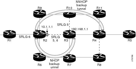
The following example shows the protection (NNHOP and SRLG) that was set on the auto-tunnel backup.


RP/0/RSP0/CPU0:router# show mpls traffic-eng tunnels 1
Signalling Summary:
              LSP Tunnels Process:  running
                     RSVP Process:  running
                       Forwarding:  enabled
          Periodic reoptimization:  every 3600 seconds, next in 2524 seconds
           Periodic FRR Promotion:  every 300 seconds, next in 49 seconds
          Auto-bw enabled tunnels:  1

Name: tunnel-te1  Destination: 200.0.0.3 (auto backup)
  Status:
    Admin:    up Oper:   up   Path:  valid   Signalling: connected

    path option 10,  type explicit (autob_nnhop_srlg_tunnel1) (Basis for Setup, path weight 11)
    path option 20,  type explicit (autob_nnhop_tunnel1)
    G-PID: 0x0800 (derived from egress interface properties)
    Bandwidth Requested: 0 kbps  CT0
    Creation Time: Fri Jul 10 01:53:25.581 PST  (1h 25m 17s ago)

  Config Parameters:
    Bandwidth:        0 kbps (CT0) Priority:  7  7 Affinity: 0x0/0xffff
    Metric Type: TE (default)
    AutoRoute: disabled  LockDown: disabled   Policy class: not set
    Forwarding-Adjacency: disabled
    Loadshare:          0 equal loadshares
    Auto-bw: disabled
    Fast Reroute: Disabled, Protection Desired: None
    Path Protection: Not Enabled
  Auto Backup:
     Protected LSPs: 4
     Protected S2L Sharing Families: 0
     Protected S2Ls: 0
     Protected i/f: Gi0/1/0/0     Protected node: 20.0.0.2
     Protection: NNHOP+SRLG
     Unused removal timeout: not running
  History:
    Tunnel has been up for: 00:00:08
    Current LSP:
      Uptime: 00:00:08
    Prior LSP:
      ID: path option 1 [545]
      Removal Trigger: configuration changed

  Path info (OSPF 0 area 0):
  Hop0: 10.0.0.2
  Hop1: 100.0.0.2
  Hop2: 100.0.0.3
  Hop3: 200.0.0.3

The following example shows automatically created path options for this backup auto-tunnel.


RP/0/RSP0/CPU0:router# show mpls traffic-eng tunnels 1 detail 
Signalling Summary:
              LSP Tunnels Process:  running
                     RSVP Process:  running
                       Forwarding:  enabled
          Periodic reoptimization:  every 3600 seconds, next in 2524 seconds
           Periodic FRR Promotion:  every 300 seconds, next in 49 seconds
          Auto-bw enabled tunnels:  1

Name: tunnel-te1  Destination: 200.0.0.3 (auto backup)
  Status:
    Admin:    up Oper:   up   Path:  valid   Signalling: connected

    path option 10,  type explicit (autob_nnhop_srlg_tunnel1) (Basis for Setup, path weight 11)
    path option 20,  type explicit (autob_nnhop_tunnel1)
    G-PID: 0x0800 (derived from egress interface properties)
    Bandwidth Requested: 0 kbps  CT0
    Creation Time: Fri Jul 10 01:53:25.581 PST  (1h 25m 17s ago)

  Config Parameters:
    Bandwidth:        0 kbps (CT0) Priority:  7  7 Affinity: 0x0/0xffff
    Metric Type: TE (default)
    AutoRoute: disabled  LockDown: disabled   Policy class: not set
    Forwarding-Adjacency: disabled
    Loadshare:          0 equal loadshares
    Auto-bw: disabled
    Fast Reroute: Disabled, Protection Desired: None
    Path Protection: Not Enabled
  Auto Backup (NNHOP+SRLG):
     Protected LSPs: 4
     Protected S2L Sharing Families: 0
     Protected S2Ls: 0
     Protected i/f: Gi0/1/0/0     Protected node: 20.0.0.2
     Protection: NNHOP+SRLG
     Unused removal timeout: not running

     Path Options Details:
      10: Explicit Path Name: (autob_nnhop_srlg_te1)
        1: exclude-srlg 50.0.0.1
        2: exclude-address 50.0.0.2
        3: exclude-node 20.0.0.2
      20: Explicit Path Name: (autob_nnhop_te1)
        1: exclude-address 50.0.0.1
        2: exclude-address 50.0.0.2
        3: exclude-node 20.0.0.2
  History:
    Tunnel has been up for: 00:00:08
    Current LSP:
      Uptime: 00:00:08
    Prior LSP:
      ID: path option 1 [545]
      Removal Trigger: configuration changed

  Path info (OSPF 0 area 0):
  Hop0: 10.0.0.2
  Hop1: 100.0.0.2
  Hop2: 100.0.0.3
  Hop3: 200.0.0.3

This example shows the automatically created backup tunnels.


RP/0/RSP0/CPU0:router# show mpls traffic-eng tunnels brief 

            TUNNEL NAME         DESTINATION      STATUS  STATE
              tunnel-te0           200.0.0.3          up  up
              tunnel-te1           200.0.0.3          up  up
              tunnel-te2           200.0.0.3          up  up
            tunnel-te50           200.0.0.3          up  up
            *tunnel-te60           200.0.0.3          up  up
            *tunnel-te70           200.0.0.3          up  up
            *tunnel-te80           200.0.0.3          up  up

RP/0/RSP0/CPU0:router# show mpls traffic-eng tunnels tabular 
            Tunnel    LSP     Destination          Source             FRR    LSP  Path
              Name     ID         Address         Address   State   State   Role  Prot
------------------ ------ --------------- --------------- ------- ------- ------ -----
        tunnel-te0    549       200.0.0.3       200.0.0.1      up   Inact   Head InAct
        tunnel-te1    546       200.0.0.3       200.0.0.1      up   Inact   Head InAct
        tunnel-te2      6       200.0.0.3       200.0.0.1      up   Inact   Head InAct
      tunnel-te50      6       200.0.0.3       200.0.0.1      up  Active   Head InAct
      tunnel-te60      4       200.0.0.3       200.0.0.1      up  Active   Head InAct
      tunnel-te70      4       200.0.0.3       200.0.0.1      up  Active   Head InAct
      tunnel-te80      3       200.0.0.3       200.0.0.1      up  Active   Head InAct

This example shows the auto-tunnel backup details.

RP/0/RSP0/CPU0:router#  show mpls traffic-eng tunnels auto-tunnel backup detail

Name: tunnel-te400  Destination: 10.0.0.1 (auto-tunnel backup)
  Status:
    Admin:    up Oper:   up   Path:  valid   Signalling: connected
 
    path option 20,  type explicit (autob_nnhop_te400) (Basis for Setup, path weight 2)
    path option 10,  type explicit (autob_nnhop_srlg_te400) [disabled]
    G-PID: 0x0800 (derived from egress interface properties)
    Bandwidth Requested: 0 kbps  CT0
    Creation Time: Thu Aug 16 18:30:41 2012 (00:01:28 ago)
  Config Parameters:
    Bandwidth:        0 kbps (CT0) Priority:  7  7 Affinity: 0x0/0xffff
    Metric Type: TE (default)
    Metric Type: TE (default)
    Hop-limit: disabled
    AutoRoute: disabled  LockDown: disabled   Policy class: not set
    Forwarding-Adjacency: disabled
    Loadshare:          0 equal loadshares
    Auto-bw: disabled
    Fast Reroute: Disabled, Protection Desired: None
    Path Protection: Not Enabled
    Soft Preemption: Disabled
  Auto Backup:
    Protected LSPs: 1
    Protected S2L Sharing Families: 0
    Protected S2L: 0
    Protected i/f: Gi0/1/0/3    Protected node: 192.168.0.1
    Attribute-set: ab1
    Protection: NNHOP
    Unused removal timeout: not running
    Path Option Details:
      10: Explicit Path Name: (autob_nnhop_srlg_te400)
        1: exclude-srlg 34.9.0.4
        2: exclude-address 34.9.0.3
        3: exclude-node 192.168.0.1
      20: Explicit Path Name: (autob_nnhop_te400)
        1: exclude-address 34.9.0.4
        2: exclude-address 34.9.0.3
        3: exclude-node 192.168.0.1
  SNMP Index: 221
  History:
    Tunnel has been up for: 00:00:34 (since Thu Aug 16 18:31:35 EST 2012)
    Current LSP:
      Uptime: 00:00:34 (since Thu Aug 16 18:31:35 EST 2012)
  Current LSP Info:
    Instance: 2, Signaling Area: OSPF 100 area 10.2.3.4
    Uptime: 00:00:34 (since Thu Aug 16 18:31:35 EST 2012)
    Outgoing Interface: GigabitEthernet0/1/0/2, Outgoing Label: 16000
    Router-IDs: local      209.165.201.1
                downstream 172.16.0.1
    Soft Preemption: None
    Path Info:
      Outgoing:
        Explicit Route:
          Strict, 24.9.0.2
          Strict, 12.9.1.1
          Strict, 10.0.0.1
 
      Record Route: Empty
      Tspec: avg rate=0 kbits, burst=1000 bytes, peak rate=0 kbits
      Session Attributes: Local Prot: Not Set, Node Prot: Not Set, BW Prot: Not Set
                          Soft Preemption Desired: Not Set
    Resv Info:
      Record Route:
        IPv4 24.9.0.2, flags 0x0
        IPv4 12.9.1.1, flags 0x0
      Fspec: avg rate=0 kbits, burst=1000 bytes, peak rate=0 kbits
Displayed 1 (of 104) heads, 0 (of 0) midpoints, 0 (of 201) tails
Displayed 1 up, 0 down, 0 recovering, 0 recovered heads

This example shows the automatically created backup tunnels.


RP/0/RSP0/CPU0:router# show mpls traffic-eng tunnels auto-tunnel backup tabular

           Tunnel   LSP     Destination          Source    Tun    FRR  LSP  Path
             Name    ID         Address         Address  State  State Role  Prot
----------------- ----- --------------- --------------- ------ ------ ---- -----
    *tunnel-te400     2         10.0.0.1         209.165.201.1     up  Inact Head Inact
    *tunnel-te401     2         192.168.0.1         209.165.201.1     up  Inact Head Inact
* = automatically created backup tunnel

RP/0/RSP0/CPU0:router# show mpls traffic-eng tunnels auto-tunnel backup brief
           TUNNEL NAME         DESTINATION      STATUS  STATE
         *tunnel-te400             10.0.0.1          up  up
         *tunnel-te401             192.168.0.1          up  up
* = automatically created backup tunnel
Displayed 2 (of 104) heads, 0 (of 0) midpoints, 0 (of 201) tails
Displayed 2 up, 0 down, 0 recovering, 0 recovered heads
 

This example shows the attribute-set for auto-backup tunnels.

RP/0/RSP0/CPU0:router# show mpls traffic-eng attribute-set auto-backup

Attribute Set Name: ab (Type: auto-backup)
  Number of affinity constraints: 2
     Include bit map       : 0x4
     Include name          : blue
     Exclude bit map       : 0x2
     Exclude name          : red
  Priority: 7 7 (Default)
  Record-route: Enabled
  Policy-class: 1
  Logging: reoptimize, state
  List of protected interfaces (count 1)
      POS0_3_0_1
  List of tunnel IDs (count 1)
    3000

This example shows the attribute-set for auto-mesh tunnels.

RP/0/RSP0/CPU0:router# show mpls traffic-eng attribute-set auto-mesh

Attribute Set Name: am (Type: auto-mesh)
  Bandwidth: 100 kbps (CT0)
  Number of affinity constraints: 2
     Include bit map       : 0x8
     Include name          : yellow
     Exclude bit map       : 0x2
     Exclude name          : red
  Priority: 2 2
  Interface Bandwidth: 0 kbps (Default)
  AutoRoute Announce: Disabled
  Auto-bw: Disabled
  Soft Preemption: Disabled
  Fast Reroute: Enabled, Protection Desired: Node, Bandwidth
  Record-route: Enabled
  Policy-class: 0 (Not configured)
  Logging: None
  List of Mesh Groups (count 1)
    1
 

This example shows the details about the tunnel that is using auto-backup type of attribute-set.

RP/0/RSP0/CPU0:router# show mpls traffic-eng tunnels attribute-set auto-backup ab 

Name: tunnel-te3000  Destination: 10.0.0.1 (auto-tunnel backup)
  Status:
    Admin:    up Oper:   up   Path:  valid   Signalling: connected

    path option 20,  type explicit (autob_nhop_te3000) (Basis for Setup, path weight 2)
    path option 10,  type explicit (autob_nhop_srlg_te3000) [disabled]
    G-PID: 0x0800 (derived from egress interface properties)
    Bandwidth Requested: 0 kbps  CT0
    Creation Time: Tue Aug 14 23:24:27 2012 (00:05:28 ago)
  Config Parameters:
    Bandwidth:        0 kbps (CT0) Priority:  7  7
    Number of affinity constraints: 2
       Include bit map       : 0x4
       Include name          : blue
       Exclude bit map       : 0x2
       Exclude name          : red

    Metric Type: TE (default)
    Hop-limit: disabled
    AutoRoute: disabled  LockDown: disabled   Policy class: 1
    Forwarding-Adjacency: disabled
    Loadshare:          0 equal loadshares
    Auto-bw: disabled
    Fast Reroute: Disabled, Protection Desired: None
    Path Protection: Not Enabled
    Soft Preemption: Disabled
  Auto Backup:
    Protected LSPs: 2
    Protected S2L Sharing Families: 0
    Protected S2L: 0
    Protected i/f: PO0/3/0/1
    Attribute-set: ab
    Protection: NHOP
    Unused removal timeout: not running
  History:
    Tunnel has been up for: 00:04:57 (since Tue Aug 14 23:24:58 EST 2012)
    Current LSP:
      Uptime: 00:04:57 (since Tue Aug 14 23:24:58 EST 2012)

  Path info (OSPF 100 area 16909060):
  Node hop count: 2
  Hop0: 23.9.0.2
  Hop1: 12.9.0.2
  Hop2: 12.9.0.1
  Hop3: 10.0.0.1
Displayed 1 (of 7) heads, 0 (of 3) midpoints, 0 (of 0) tails Displayed 1 up, 0 down, 0 recovering, 0 recovered heads

This example shows the protected interface for auto-backup auto-tunnels.

RP/0/RSP0/CPU0:router# show mpls traffic-eng tunnels backup protected-interface 

Interface: Gi0/2/0/1 (auto-tunnel backup)
  SRLG: N/A, NHOP-only: No
  Attribute-set: Not configured
  Auto-tunnel backup recreate time remaining:  timer not running
    No backup tunnel found

Interface: Gi0/2/0/3
     tunnel-te340   PROTECTED : out i/f:   PO0/3/0/2   Admin:   up  Oper:   up

Interface: PO0/3/0/1 (auto-tunnel backup)
  SRLG: N/A, NHOP-only: No
  Attribute-set: ab
  Auto-tunnel backup recreate time remaining:  timer not running
    *tunnel-te3000        NHOP : out i/f:   Gi0/2/0/2   Admin:   up  Oper:   up

 * = automatically created backup tunnel

This example shows the details about all the tunnels that are using auto-mesh type of attribute-set.

RP/0/RSP0/CPU0:router# show mpls traffic-eng tunnels attribute-set auto-mesh all 

Name: tunnel-te3501  Destination: 10.0.0.1 (auto-tunnel mesh)
  Status:
    Admin:    up Oper:   up   Path:  valid   Signalling: connected

    path option 10,  type dynamic  (Basis for Setup, path weight 2)
    G-PID: 0x0800 (derived from egress interface properties)
    Bandwidth Requested: 100 kbps  CT0
    Creation Time: Tue Aug 14 23:25:41 2012 (00:06:13 ago)
  Config Parameters:
    Bandwidth:      100 kbps (CT0) Priority:  2  2
    Number of affinity constraints: 2
       Include bit map       : 0x8
       Include name          : yellow
       Exclude bit map       : 0x2
       Exclude name          : red

    Metric Type: TE (default)
    Hop-limit: disabled
    AutoRoute: disabled  LockDown: disabled   Policy class: not set
    Forwarding-Adjacency: disabled
    Loadshare:          0 equal loadshares
    Auto-bw: disabled
    Fast Reroute: Enabled, Protection Desired: Node, Bandwidth
    Path Protection: Not Enabled
    Attribute-set: am (type auto-mesh)
    Soft Preemption: Disabled
  Auto-tunnel Mesh:
    Group ID: 1
    Destination list: blah
    Unused removal timeout: not running
  History:
    Tunnel has been up for: 00:06:13 (since Tue Aug 14 23:25:41 EST 2012)
    Current LSP:
      Uptime: 00:06:13 (since Tue Aug 14 23:25:41 EST 2012)

  Path info (OSPF 100 area 16909060):
  Node hop count: 2
  Hop0: 23.9.0.2
  Hop1: 12.9.0.2
  Hop2: 12.9.0.1
  Hop3: 10.0.0.1

Name: tunnel-te3502  Destination: 172.16.0.1 (auto-tunnel mesh)
  Status:
    Admin:    up Oper:   up   Path:  valid   Signalling: connected

    path option 10,  type dynamic  (Basis for Setup, path weight 1)
    G-PID: 0x0800 (derived from egress interface properties)
    Bandwidth Requested: 100 kbps  CT0
    Creation Time: Tue Aug 14 23:25:41 2012 (00:06:13 ago)
  Config Parameters:
    Bandwidth:      100 kbps (CT0) Priority:  2  2
    Number of affinity constraints: 2
       Include bit map       : 0x8
       Include name          : yellow
       Exclude bit map       : 0x2
       Exclude name          : red

    Metric Type: TE (default)
    Hop-limit: disabled
    AutoRoute: disabled  LockDown: disabled   Policy class: not set
    Forwarding-Adjacency: disabled
    Loadshare:          0 equal loadshares
    Auto-bw: disabled
    Fast Reroute: Enabled, Protection Desired: Node, Bandwidth
    Path Protection: Not Enabled
    Attribute-set: am (type auto-mesh)
    Soft Preemption: Disabled
  Auto-tunnel Mesh:
    Group ID: 1
    Destination list: blah
    Unused removal timeout: not running
  History:
    Tunnel has been up for: 00:06:13 (since Tue Aug 14 23:25:41 EST 2012)
    Current LSP:
      Uptime: 00:06:13 (since Tue Aug 14 23:25:41 EST 2012)

  Path info (OSPF 100 area 16909060):
  Node hop count: 1
  Hop0: 23.9.0.2
  Hop1: 172.16.0.1

Name: tunnel-te3503  Destination: 209.165.201.1 (auto-tunnel mesh)
  Status:
    Admin:    up Oper: down   Path: not valid   Signalling: Down

    path option 10,  type dynamic
    Last PCALC Error: Tue Aug 14 23:31:26 2012
      Info: No path to destination, 209.165.201.1 (affinity)
    G-PID: 0x0800 (derived from egress interface properties)
    Bandwidth Requested: 100 kbps  CT0
    Creation Time: Tue Aug 14 23:25:41 2012 (00:06:13 ago)
  Config Parameters:
    Bandwidth:      100 kbps (CT0) Priority:  2  2
    Number of affinity constraints: 2
       Include bit map       : 0x8
       Include name          : yellow
       Exclude bit map       : 0x2
       Exclude name          : red

    Metric Type: TE (default)
    Hop-limit: disabled
    AutoRoute: disabled  LockDown: disabled   Policy class: not set
    Forwarding-Adjacency: disabled
    Loadshare:          0 equal loadshares
    Auto-bw: disabled
    Fast Reroute: Enabled, Protection Desired: Node, Bandwidth
    Path Protection: Not Enabled
    Attribute-set: am (type auto-mesh)
    Soft Preemption: Disabled
  Auto-tunnel Mesh:
    Group ID: 1
    Destination list: blah
    Unused removal timeout: not running
Displayed 3 (of 7) heads, 0 (of 3) midpoints, 0 (of 0) tails Displayed 2 up, 1 down, 0 recovering, 0 recovered heads

Bandwidth Protection Functions to Enhance auto-tunnel backup Capabilities

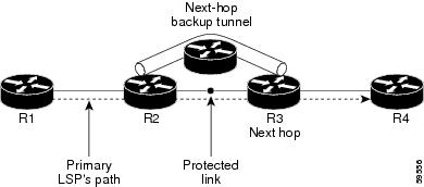
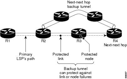
Without bandwidth protection, auto-tunnel backups provide only link protection and node protection (per next-next-hop), and backup tunnels are signalled with zero bandwidth. This causes traffic congestion when FRR goes active, since the backup tunnels might be protecting huge amount of data, such as LSPs with large bandwidth or multiple LSPs.

To address the congestion issue, bandwidth protection capabilities are added for auto-tunnel backups. Bandwidth protection, signalled bandwidth, and soft-preemption settings are provided. Details:
  • Bandwidth protection – A link or node protection backup might not provide bandwidth protection. But with this setting (bandwidth-protection maximum-aggregate), you can set the maximum bandwidth value that an auto-tunnel can protect.

  • Signalled bandwidth – Without bandwidth protection, auto-tunnel backups are signaled with zero bandwidth too, with no guarantee that at least some bandwidth is backed up. So, the backup tunnels might be setup on links that are highly utilized, causing congestion drops when the backup tunnels start to transmit traffic after FRR is triggered.

    This setting (signalled-bandwidth) addresses the issue, since you can set the signalled bandwidth of the tunnel (and reserve minimal bandwidth for an auto-tunnel backup). When you set the signal bandwidth value for auto-backup tunnels, congestion over backup links reduces.

  • Soft-preemption – Since bandwidth can be reserved for autobackup tunnels, a setting (soft-preemption) is provided for soft-preemption of the reserved bandwidth, if it is needed for a higher-priority tunnel.

Configurations

/*Enable Bandwidth Protection On a TE Auto-Tunnel Backup*/

Router# configure
Router(config)# mpls traffic-eng   
Router(config-mpls-te)# interface GigabitEthernet 0/2/0/0 auto-tunnel backup  
Router(config-te-if-auto-backup)# bandwidth-protection maximum-aggregate 100000 
Router(config-te-if-auto-backup)# commit

/*Enable Signalled Bandwidth On a TE Auto-Tunnel Backup*/

Router# configure  
Router(config)# mpls traffic-eng attribute-set auto-backup MyBackupConfig  
Router(config-te-attribute-set)# signalled-bandwidth 700000 
Router(config-te-attribute-set)# commit 

After creating the auto backup attribute-set (MyBackupConfig in this case), associate with the auto-tunnel backup interface.

Router# configure
Router(config)# mpls traffic-eng   
Router(config-mpls-te)# interface GigabitEthernet 0/2/0/0 auto-tunnel backup  
Router(config-te-if-auto-backup)# attribute-set MyBackupConfig   
Router(config-te-if-auto-backup)# auto-tunnel backup tunnel-id min 6000 max 6500  
Router(config-mpls-te)# commit

/*Enable Soft-Preemption Bandwidth On a TE Auto-Tunnel Backup*/

Router# configure
Router(config)# mpls traffic-eng attribute-set auto-backup MyBackupConfig 
Router(config-te-attribute-set)# soft-preemption
Router(config-te-attribute-set)# commit

Verification

/*Verify Auto-Tunnel Backup Configuration*/

In the output, bandwidth protection details are displayed, as denoted by BW.

Router# show mpls traffic-eng auto-tunnel backup

AutoTunnel Backup Configuration:
    Interfaces count: 1
    Unused removal timeout: 1h 0m 0s
    Configured tunnel number range: 6000-6500

AutoTunnel Backup Summary:
    AutoTunnel Backups:
             0 created, 0 up, 0 down, 0 unused
             0 NHOP, 0 NNHOP, 0 SRLG strict, 0 SRLG preferred, 0 SRLG weighted, 0 BW protected
  Protected LSPs:
             0 NHOP, 0 NHOP+SRLG, 0 NHOP+BW, 0 NHOP+BW+SRLG
             0 NNHOP, 0 NNHOP+SRLG, 0 NNHOP+BW, 0 NNHOP+BW+SRLG
    Protected S2L Sharing Families:
             0 NHOP, 0 NHOP+SRLG, 0 NNHOP+BW, 0 NNHOP+BW+SRLG
             0 NNHOP, 0 NNHOP+SRLG, 0 NNHOP+BW, 0 NNHOP+BW+SRLG
    Protected S2Ls:
             0 NHOP, 0 NHOP+SRLG, 0 NNHOP+BW, 0 NNHOP+BW+SRLG
             0 NNHOP, 0 NNHOP+SRLG, 0 NNHOP+BW, 0 NNHOP+BW+SRLG

 Cumulative Counters (last cleared 00:08:47 ago):
                         Total   NHOP  NNHOP
    Created:               0       0      0
    Connected:             0       0      0
    Removed (down):        0       0      0
    Removed (unused):      0       0      0
    Removed (in use):      0       0      0
    Range exceeded:        0       0      0

Configure Point-to-Multipoint TE: Examples

These configuration examples show how to configure Point-to-Multipoint TE:

P2MP Topology Scenario: Example

This section describes a typical scenario of point-to-multipoint traffic engineering toplogy. This figure illustrates the P2MP toplogy.

Figure 19. P2MP Topology
P2MP Topology
This head router describes the configuration at head node. This router does the imposition of MPLS at head node.

interface tunnel-mte1
 ipv4 unnumbered Loopback0
 destination 10.0.0.1
  path-option 1 explicit name path-to-tail1
 !
 destination 172.16.0.1
  path-option 1 explicit name path-to-tail2
 !
 fast-reroute

mpls traffic-eng
 interface GigabitEthernet0/1/3/0
!
 interface GigabitEthernet0/1/3/7
 !

multicast-routing
 address-family ipv4
  nsf
  interface all enable
 !
 address-family ipv6
  nsf
  interface all enable
 !
!
 !
router igmp
 vrf default
  interface tunnel-mte1
   static-group 232.0.0.1 192.168.10.1
  !
This mid router describes the configuration at mid node. This router performs the role of MPLS label replication at mid node.

mpls traffic-eng
 interface POS0/2/0/0
 !
 interface POS0/2/0/1
  backup-path tunnel-te 1000
 !
 interface TenGigE0/3/0/3
 !
 interface GigabitEthernet0/2/5/0
 !
!
This tail router describes the configuration at tail node. This router performs the role of MPLS disposition at tail node.

mpls traffic-eng
 interface POS0/0/3/0
 !

!


multicast-routing
 address-family ipv4
  interface all enable
 !
 core-tree-protocol rsvp-te group-list lsm
  static-rpf 192.168.10.1 32 mpls 5.5.5.5
 !
!
This configuration describes the Fast Reroute configuration in the MPLS network.

explicit-path name backup-path-to-tail1 
 index 1 next-address strict 198.1.1.2
 index 2 next-address strick 198.1.2.2 
!

interface tunnel-te1000 <<< backup p2p tunnel
 ipv4 unnumbered Loopback0
 destination 140.140.140.140
 path-option 1 explicit name backup-path-to-tail1
!
mpls traffic-eng
 interface POS0/2/0/0
 !
 interface POS0/2/0/1
  backup-path tunnel-te 1000
 !
 interface TenGigE0/5/0/4
!

Configure Point-to-Multipoint for the Source: Example

At the source, multicast routing must be enabled on both the tunnel-mte interface and customer-facing interface. Then, the static-group must be configured on the tunnel-mte interface to forward specified multicast traffic over P2MP LSP.


Note


The multicast group address, which is in Source-Specific Multicast (SSM) address range (ff35::/16), must be used on the static-group configuration because Cisco IOS XR software supports only SSM for Label Switch Multicast (LSM). Additionally, the customer-facing interface must have an IPv6 address.


multicast-routing 
  address-family ipv6
   interface tunnel-mte 1
    enable
   !
   interface GigabitEthernet0/2/0/3  
    enable
   !
  !
 !
 router mld
  vrf default
   interface tunnel-mte 1
    static-group ff35::1 2000::1 3eFF::A 
   !
  !
 !
 interface tunnel-mte 1
    ipv4 unnumbered Loopback0
    destination 192.168.0.1   
       path-option 1 dynamic 
    destination 209.165.201.1
       path-option 1 dynamic 
 !
!

Configure the Point-to-Multipoint Tunnel: Example

There is no difference between logging events at the tunnel level for both P2P and P2MP. The P2MP tunnel reoptimizes only at the per tunnel level.


interface tunnel-mte1
      ipv4 unnumbered Loopback0
      destination 60.60.60.60
      logging events lsp-status state
      logging events lsp-status reroute
      path-option 10 explicit name toR6_via_R2andR3
     !
     logging events lsp-status reoptimize
     logging events lsp-status state
     logging events lsp-status reroute
     fast-reroute
     record-route
    !
explicit-path name PATH7
     index 1 next-address strict ipv4 unicast 192.168.7.2
     index 2 next-address strict ipv4 unicast 192.168.7.1
     index 3 next-address strict ipv4 unicast 192.168.16.1
     index 4 next-address strict ipv4 unicast 192.168.16.2
     !

Disable a Destination: Example

From the tunnel-mte interface, you can disable the destination.


interface tunnel-mte101
 ipv4 unnumbered Loopback0
 destination 150.150.150.150
  disable
  path-option 10 dynamic 
 !
 destination 150.150.150.150
  path-option 2 dynamic
 !
! 

Configure the Point-to-Multipoint Solution: Example

Requirements for MPLS-TE Configuration

Before the Point-to-Multipoint (P2MP) tunnel is defined, these MPLS-TE requirements must be configured:

  • Multiprotocol Label Switching traffic engineering (MPLS-TE)

  • Resource ReSerVation Protocol (RSVP)

  • Open Shortest Path First (OSPF)

This example shows the entire P2MP solution:

  • Source is the location where the P2MP-TE tunnel interface is created.

  • Tunnel contains multiple destinations. For example, the P2MP-TE tunnel is configured with two leaf node destinations by using the dynamic and explicit path options.

  • Fast-Reroute (FRR) is specified on the P2MP tunnel.

  • All regular TE tunnel options such as affinity or bandwidth are configured.

  • Static mapping of the group address to the P2MP tunnel is done in IGMP.

    Internet Group Management Protocol (IGMP).
  • The P2MP-TE midpoint configuration requires only TE and Interior Gateway Protocol (IGP) information.

  • The P2MP-TE receiver configuration requires a static group and RPF map.


!
explicit-path name g2-r2-r1
 index 1 next-address strict ipv4 unicast 10.2.15.1
!
explicit-path name g2-r2-r3
 index 1 next-address strict ipv4 unicast 10.2.25.1
 index 2 next-address strict ipv4 unicast 10.2.23.2
!
explicit-path name g2-r2-r4
 index 1 next-address strict ipv4 unicast 10.2.25.1
 index 2 next-address strict ipv4 unicast 10.2.24.2
!
ipv4 access-list ssm
 10 permit ipv4 232.1.0.0/16 any
 20 permit ipv4 232.3.0.0/16 any
 30 permit ipv4 232.4.0.0/16 any
!
ipv4 access-list ssm-test
 10 permit ipv4 235.0.0.0/8 any
!
interface Loopback0
 ipv4 address 192.168.1.2 255.255.255.255
!
interface tunnel-mte221
 ipv4 unnumbered Loopback0
 destination 192.168.1.1
  path-option 1 dynamic
 !
 destination 192.168.1.3
  path-option 1 dynamic
 !
 destination 192.168.1.4
  path-option 1 dynamic
 !
!
interface tunnel-mte222
 ipv4 unnumbered Loopback0
 destination 192.168.1.1
  path-option 1 explicit name g2-r2-r1
 !
 destination 192.168.1.3
  path-option 1 explicit name g2-r2-r3
 !
 destination 192.168.1.4
  path-option 1 explicit name g2-r2-r4
 !
 signalled-bandwidth 1000
!
interface MgmtEth0/RP0/CPU0/0
 ipv4 address 172.20.163.12 255.255.255.128
!
interface MgmtEth0/RP1/CPU0/0
 shutdown
!
interface GigabitEthernet0/0/0/0
 ipv4 address 172.2.1.2 255.255.255.0
 load-interval 30
!
interface GigabitEthernet0/0/0/1
 ipv4 address 10.1.15.2 255.255.255.0
!
interface GigabitEthernet0/0/0/1.2
 ipv4 address 10.2.15.2 255.255.255.0
 encapsulation dot1q 2
!
interface GigabitEthernet0/0/0/2
 ipv4 address 10.1.25.2 255.255.255.0
!
interface GigabitEthernet0/0/0/2.2
 ipv4 address 10.2.25.2 255.255.255.0
 encapsulation dot1q 2
!
interface GigabitEthernet0/0/0/3
 shutdown
!
interface GigabitEthernet0/0/0/4
 shutdown
!
interface GigabitEthernet0/0/0/5
 shutdown
!
interface GigabitEthernet0/0/0/6
 shutdown
!         
interface GigabitEthernet0/0/0/7
 shutdown
!
router static
 address-family ipv4 unicast
  0.0.0.0/0 1.56.0.1
  0.0.0.0/0 172.20.163.1
 !
!
router ospf 100
 nsr
 router-id 192.168.70.1
 area 0
  mpls traffic-eng
  interface Loopback0
  !
  interface GigabitEthernet0/0/0/0
  !
  interface GigabitEthernet0/0/0/1
  !
  interface GigabitEthernet0/0/0/1.2
  !
  interface GigabitEthernet0/0/0/2
  !
  interface GigabitEthernet0/0/0/2.2
  !
 !
 mpls traffic-eng router-id 192.168.70.1
!
mpls oam
!
rsvp
 interface GigabitEthernet0/0/0/0
  bandwidth 20000
 !
 interface GigabitEthernet0/0/0/1
  bandwidth 20000
 !
 interface GigabitEthernet0/0/0/2
  bandwidth 20000
 !
 interface GigabitEthernet0/0/0/1.2
  bandwidth 20000
 !
 interface GigabitEthernet0/0/0/2.2
  bandwidth 20000
 !
!
mpls traffic-eng
 interface GigabitEthernet0/0/0/0
 !
 interface GigabitEthernet0/0/0/1
 !
 interface GigabitEthernet0/0/0/2
 !
 interface GigabitEthernet0/0/0/1.2
 !
 interface GigabitEthernet0/0/0/2.2
 !
!
mpls ldp
 router-id 192.168.1.2
 nsr
 graceful-restart
 interface GigabitEthernet0/0/0/0
 !
 interface GigabitEthernet0/0/0/1
 !
 interface GigabitEthernet0/0/0/1.2
 !
 interface GigabitEthernet0/0/0/2
 !
 interface GigabitEthernet0/0/0/2.2
 !
!
multicast-routing
 address-family ipv4
  core-tree-protocol rsvp-te
  ssm range ssm
  static-rpf 172.1.1.1 32 mpls 192.168.1.1
  static-rpf 172.3.1.1 32 mpls 192.168.1.3
  static-rpf 172.4.1.1 32 mpls 192.168.1.4
  interface all enable
 !
!
router igmp
 !
 interface tunnel-mte221
  static-group 232.2.2.1 172.2.1.1
 !
 interface tunnel-mte222
  static-group 232.2.2.2 172.2.1.1
 !
 interface GigabitEthernet0/0/0/0
  static-group 232.1.2.1 172.1.1.1
  static-group 232.1.2.2 172.1.1.1
  static-group 232.3.2.1 172.3.1.1
  static-group 232.3.2.2 172.3.1.1
  static-group 232.4.2.1 172.4.1.1
  static-group 232.4.2.2 172.4.1.1
 !
!
end

Configure MPLS TE Path-selection Cost Limit: Example

This example shows how to set the path-selection cost limit for MPLS TE tunnels at global, TE tunnel interface, and path-option attribute-set levels. By default, the cost-limit set at path-option attribute set takes the priority, if all options are configured and per tunnel interface level takes priority over global cost-limit. At per tunnel interface level, the global cost-limit takes the priority.


interface tunnel-te1
 path-selection cost-limit 2
!
mpls traffic-eng
 attribute-set path-option PO3AttrSet
  path-selection cost-limit 3
 !
 path-selection cost-limit 1
!
!

Configuring Performance Measurement

Network performance metrics such as packet loss, delay, delay variation, and bandwidth utilization is a critical measure for traffic engineering (TE) in service provider networks. These network performance metrics provide network operators information about the performance characteristics of their networks for performance evaluation and helps to ensure compliance with service level agreements. The service-level agreements (SLAs) of service providers depend on the ability to measure and monitor these network performance metrics. Network operators can use performance measurement (PM) feature to monitor the network metrics for links as well as end-to-end TE label switched paths (LSPs).

Path Calculation Metric Type

To configure the metric type to be used for path calculation for a given tunnel, use the path-selection metric command in either the MPLS-TE configuration mode or under the tunnel interface configuration mode.

The metric type specified per interface takes the highest priority, followed by the MPLS-TE global metric type.


Note


If the delay metric is configured, CSPF finds a path with optimizedminimum link delay metric. See the Configuring Performance Measurement chapter in the Segment Routing Configuration Guide for information on configuring interface performance delay measurement.

Configuration Example

The following example shows how to set the path-selection metric to use the IGP metric under a specific tunnel interface:

Router# configure
Router(config)# interface tunnel-te 1
Router(config-if)# path-selection metric igp
Router(config-if)# commit

The following example shows how to set the path-selection metric to use the delay metric under the MPLS-TE configuration mode:

Router# configure
Router(config)# mpls traffic-eng
Router(config-mpls-te)# path-selection metric delay
Router(config-mpls-te)# commit 

Path-Selection Delay Limit

Apply the path-selection delay-limit configuration to set the upper limit on the path aggregate delay when computing paths for MPLS-TE LSPs. After you configure the path-selection delay-limit value, if the sum of minimum-delay metric from all links that are traversed by the path exceeds the specified delay-limit, CSPF will not return any path. The periodic path verification checks if the delay-limit is crossed.

The path-selection delay-limit value can be configured at the global MPLS-TE, per-interface tunnel, and per path-option attribute set. The path-selection delay-limit per path-option attribute set takes the highest priority, followed by per-interface, and then the MPLS-TE global path-selection delay-limit values.

The delay limit range is a value from 1 to 4294967295 microseconds.


Note


See the Configuring Performance Measurement chapter in the Segment Routing Configuration Guide for information on configuring interface performance delay measurement.

Configuration Example

The following example shows how to set the path-selection delay limit under a specific tunnel interface:

Router# configure
Router(config)# interface tunnel-te2000
Router(config-if)# path-selection metric delay
Router(config-if)# path-selection delay-limit 200
Router(config-if)# commit

The following example shows how to set the path-selection delay limit under a path-option attribute set:

Router# configure
Router(config)# mpls traffic-eng 
Router(config-mpls-te)# attribute-set path-option test
Router(config-te-attribute-set)# path-selection delay-limit 300
Router(config-te-attribute-set)# root
Router(config)# interface tunnel-te1000
Router(config-if)# path-option 10 dynamic attribute-set test
Router(config-if)# commit

The following example shows how to set the path-selection delay limit under the global MPLS-TE configuration mode:

Router# configure
Router(config)# mpls traffic-eng 
Router(config-mpls-te)# path-selection metric delay 
Router(config-mpls-te)# path-selection delay-limit 150
Router(config-mpls-te)# commit

Additional References

For additional information related to implementing MPLS-TE, refer to the following references:

Related Documents

Related Topic

Document Title

MPLS-TE commands

MPLS Traffic Engineering Commands module in MPLS Command Reference for Cisco ASR 9000 Series Routers.

Standards

Standards

Title

No new or modified standards are supported by this feature, and support for existing standards has not been modified by this feature.

MIBs

MIBs

MIBs Link

To locate and download MIBs using Cisco IOS XR software, use the Cisco MIB Locator found at the following URL and choose a platform under the Cisco Access Products menu: http://cisco.com/public/sw-center/netmgmt/cmtk/mibs.shtml

RFCs

RFCs

Title

RFC 4124

Protocol Extensions for Support of Diffserv-aware MPLS Traffic Engineering, F. Le Faucheur, Ed. June 2005.

(Format: TXT=79265 bytes) (Status: PROPOSED STANDARD)

RFC 4125

Maximum Allocation Bandwidth Constraints Model for Diffserv-aware MPLS Traffic Engineering, F. Le Faucheur, W. Lai. June 2005.

(Format: TXT=22585 bytes) (Status: EXPERIMENTAL)

RFC 4127

Russian Dolls Bandwidth Constraints Model for Diffserv-aware MPLS Traffic Engineering, F. Le Faucheur, Ed. June 2005.

(Format: TXT=23694 bytes) (Status: EXPERIMENTAL)

Technical Assistance

Description

Link

The Cisco Technical Support website contains thousands of pages of searchable technical content, including links to products, technologies, solutions, technical tips, and tools. Registered Cisco.com users can log in from this page to access even more content.

http://www.cisco.com/techsupport