Introduction to Traffic Mirroring
Traffic mirroring, which is sometimes called port mirroring, or Switched Port Analyzer (SPAN) is a Cisco proprietary feature that enables you to monitor Layer 2 or Layer 3 network traffic passing in, or out of, a set of Ethernet interfaces. You can then pass this traffic to a network analyzer for analysis.
Traffic mirroring copies traffic from one or more Layer 3 or Layer 2 interfaces or sub-interfaces, including Layer 2 link bundle interfaces or sub-interfaces, and sends the copied traffic to one or more destinations for analysis by a network analyzer or other monitoring device. Traffic mirroring does not affect the switching of traffic on the source interfaces or sub-interfaces, and allows the mirrored traffic to be sent to a destination interfaceor sub-interface.
Traffic mirroring was introduced on switches because of a fundamental difference between switches and hubs. When a hub receives a packet on one port, the hub sends out a copy of that packet from all ports except from the one at which the hub received the packet. In the case of switches, after a switch boots, it starts to build up a Layer 2 forwarding table on the basis of the source MAC address of the different packets that the switch receives. After this forwarding table is built, the switch forwards traffic that is destined for a MAC address directly to the corresponding port.
For example, if you want to capture Ethernet traffic that is sent by host A to host B, and both are connected to a hub, just attach a traffic analyzer to this hub. All other ports see the traffic between hosts A and B.

On a switch or router, after the host B MAC address is learned, unicast traffic from A to B is only forwarded to the B port. Therefore, the traffic analyzer does not see this traffic.

In this configuration, the traffic analyzer captures only traffic that is flooded to all ports, such as:
-
Broadcast traffic
-
Multicast traffic with CGMP or Internet Group Management Protocol (IGMP) snooping disabled
-
Unknown unicast traffic on a switch
An extra feature is necessary that artificially copies unicast packets that host A sends. This extra feature is traffic mirroring. When traffic mirroring is enabled, the traffic analyzer is attached to a port that is configured to receive a copy of every packet that host A sends. This port is called a traffic mirroring port. The other sections of this document describe how you can fine tune this feature.
Sampled Traffic Mirroring
SPAN is supported on all types of forwarding interfaces of the main interface (port level) such as, L2, L3 interfaces, sub-interface, bundle interface, and BNG interface. But Sampled SPAN is supported only at port level. Sampled SPAN is configurable in ingress direction only. SPAN and Sampled SPAN cannot be configured at the same time on main interface (at port level). When Sampled SPAN is enabled on main interface, SPAN is still configurable on rest of the forwarding interfaces on the port.
When Sampled SPAN is enabled on the underlying physical port and SPAN is configured on a forwarding interface, the packets are mirrored as follows:
-
Sampled packet on the physical port is mirrored just to the destination port of the Sampled SPAN session.
-
Non-sampled packet is mirrored for each of the regular SPAN session on the associated forwarding interface.
Sampled Traffic Mirroring allows you to:
-
Sample the packets based on a configured interval.
-
Apply Sampled SPAN on a physical port in order to include all forwarding interfaces on that port.
-
Configure the Sampling rate of monitoring that is configured for each source port. You can choose to configure one of these sampling rates; 1K, 2K, 4K, 8K, and 16K. For example, when 4K is configured as the sampling rate, for every 4K packets on the source port one packet is sampled and mirrored to the destination port.
-
Use Sampled SPAN along with Traffic Mirroring.
-
Enable Sampled SPAN on every bundle member, if the physical port is part of a link bundle.
-
Use all destination ports that were supported for SPAN.
-
Enable statistics support on each monitoring session.
-
Truncate and mirror a fixed portion of each mirrored packet (for example, the first 64 bytes of every packet received from the source port is mirrored to the destination port). You can configure the offset or the amount of fixed portion.
You can configure these source to destination combinations in sampled SPAN:
-
Physical Port mirrored to Physical Port
-
Physical Port mirrored to Pseudo-wire
-
Bundle member port mirrored to Physical Port
-
Bundle member port mirrored to Pseudo-wire
Implementing Traffic Mirroring on the Cisco ASR 9000 Series Router
Traffic Mirroring Terminology
-
Ingress traffic—Traffic that enters the switch.
-
Egress traffic—Traffic that leaves the switch.
-
Source port—A port that is monitored with the use of traffic mirroring. It is also called a monitored port.
-
Destination port—A port that monitors source ports, usually where a network analyzer is connected. It is also called a monitoring port.
-
Monitor session—A designation for a collection of traffic mirroring configurations consisting of a single destination and, potentially, many source interfaces.
Characteristics of the Source Port
A source port, also called a monitored port, is a switched or routed port that you monitor for network traffic analysis. In a single local or remote traffic mirroring session, you can monitor source port traffic, such as received (Rx) for ingress traffic, transmitted (Tx) for egress traffic, or bidirectional (for both ingress and egress traffic). Your router can support any number of source ports (up to a maximum number of 800).
A source port has these characteristics:
-
It can be any port type, such as Bundle Interface, Gigabit Ethernet, 10-Gigabit Ethernet, or EFPs.

Note
Bridge group virtual interfaces (BVIs) are not supported.
-
Each source port can be monitored in only one traffic mirroring session.
-
It cannot be a destination port.
-
Partial Packet Mirroring. The first 64 to 256 bytes of the packet can be mirrored.
-
Each source port can be configured with a direction (ingress, egress, or both) to monitor. For bundles, the monitored direction applies to all physical ports in the group.
Figure 2. Network Analysis on a Cisco ASR 9000 RouterWith Traffic Mirroring
In the figure above, the network analyzer is attached to a port that is configured to receive a copy of every packet that host A sends. This port is called a traffic mirroring port.
Characteristics of the Monitor Session
A monitor session is a collection of traffic mirroring configurations consisting of a single destination and, potentially, many source interfaces. For any given monitor session, the traffic from the source interfaces (called source ports) is sent to the monitoring port (called the destination port) . Some optional operations such as VLAN tag imposition and ACL filtering can be performed on the mirrored traffic streams. If there is more than one source port in a monitoring session, the traffic from the several mirrored traffic streams is combined at the destination port. The result is that the traffic that comes out of the destination port is a combination of the traffic from one or more source ports, and the traffic from each source port may or may not have VLAN push operations or ACLs applied to it.
Monitor sessions have these characteristics:
-
A single Cisco ASR 9000 Router can have a maximum of eight monitor sessions.
-
A single monitor session can have only one destination port.
-
A single destination port can belong to only one monitor session.
-
A single Cisco ASR 9000 Router can have a maximum of 800 source ports.
-
A monitor session can have a maximum of 800 source ports, as long as the maximum number of source ports from all monitoring sessions does not exceed 800.
Characteristics of the Destination Port
|
Feature Name |
Release |
Description |
|---|---|---|
|
SPAN support for bundle as a destination interface |
Release 7.5.1 |
This feature adds the ability to configure a bundle destination for SPAN. Bundle interfaces increase the bandwidth by allowing forwarding across all available members of the bundle. Additionally, they provide redundancy in the case of link failure. |
Each local session or remote destination session must have a destination port (also called a monitoring port) that receives a copy of the traffic from the source ports.
A destination port has these characteristics:
-
A destination port must reside on the same router as the source port.
-
A destination port can be any Ethernet physical port, EFP, pseudowire, or a bundle interface.
-
A destination port can only be a Layer 2 transport interface. An L3 interface as a SPAN destination cannot be configured on the Cisco ASR 9000 Series Router.
-
A destination port can be a trunk (main) interface or a subinterface.
-
At any one time, a destination port can participate in only one traffic mirroring session. A destination port in one traffic mirroring session cannot be a destination port for a second traffic mirroring session. In other words, no two monitor sessions can have the same destination port.
-
A destination port cannot also be a source port.
-
Figure 3. Network Analysis on a Cisco ASR 9000 Router With Traffic Mirroring
|
1 
|
Source traffic mirroring ports (can be ingress or egress traffic ports) |
2 |
Destination traffic mirroring port |
Supported Traffic Mirroring Types
These traffic mirroring types are supported:
-
Local traffic mirroring. This is the most basic form of traffic mirroring. The network analyzer or sniffer is directly attached to the destination interface. In other words, all monitored ports are all located on the same switch as the destination port.
-
Remote traffic mirroring (known as R-SPAN). In this case, the network analyzer is not attached directly to the destination interface, but is on a VLAN accessible to the switch. For example, the destination interface is a sub-interface with a VLAN encapsulation.
A restricted form of remote traffic mirroring can be implemented by sending traffic to a single destination port that pushes a VLAN tag, instead of switching through a bridge domain. Remote traffic mirroring:
-
Allows decoupling of the network analyzer and destination, but there is no on-the-box redundancy.
-
Allows multiple remote network analyzers as long as they can attach to the traffic mirroring VLAN.
This is supported on Cisco IOS XR software because the destination port is an EFP that can push a VLAN tag.
-
-
Pseudowire traffic mirroring (known as PW-SPAN in Cisco IOS Software). Instead of using a standard destination interface, traffic is mirrored to a remote site through an MPLS pseudowire.
-
ACL-based traffic mirroring. Traffic is mirrored based on the configuration of the global interface ACL.
-
Partial Packet Mirroring. The first 64 to 256 bytes of the packet can be mirrored.
-
Layer 2 or Layer 3 traffic mirroring is supported. Both Layer 2 and Layer 3 source ports can be mirrored.
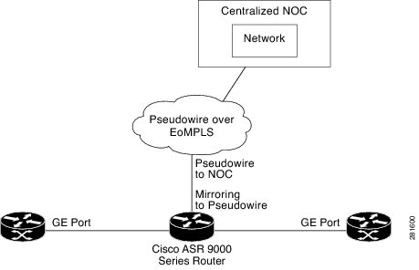
Pseudowire Traffic Mirroring
You can configure the traffic mirroring destination port to be a pseudowire rather than a physical port. In this case, the system mirrors the designated traffic on the source port over the pseudowire to a central location. This allows the centralization of expensive network traffic analysis tools.
Because the pseudowire carries only mirrored traffic, this traffic is unidirectional. There must not be any traffic coming from the remote provider edge.
In such a pseudowire traffic mirroring scenario, though the system mirrors traffic successfully, the statistics for sent pseudowire packet statistics remains zero.
To protect the pseudowire traffic mirroring path against network failures, it is possible to configure a traffic engineering tunnel as the preferred path and enable fast reroute protection for the pseudowire.
ACL-Based Traffic Mirroring
You can mirror traffic based on the definition of a global interface access list (ACL). If you are mirroring Layer 2 traffic, the ACL is configured using the ethernet-services access-list command with the capture keyword. When you are mirroring Layer 3 traffic, the ACL is configured using the ipv4 access-list or ipv6 access-list command with the capture keyword. The permit and deny commands determine the behavior of regular traffic. The capture keyword designates that the packet is to be mirrored to the destination port.
 Feedback