Implementing Multipoint Layer 2 Services

This module provides the conceptual and configuration information for Multipoint Layer 2 Bridging Services, also called Virtual Private LAN Services (VPLS).


Note

VPLS supports Layer 2 VPN technology and provides transparent multipoint Layer 2 connectivity for customers. This approach enables service providers to host a multitude of new services such as broadcast TV and Layer 2 VPNs.


For Point to Point Layer 2 Services, see Implementing Point to Point Layer 2 Services chapter.

For descriptions of the commands listed in this module, see the “Related Documents” section.

Feature History for Implementing Multipoint Layer 2 Services

Release Modification
Release 3.7.2 This feature was introduced.
Release 3.9.0 These features were added:
  • Blocking unknown unicast flooding.
  • Disabling MAC flush.

  • Multiple Spanning Tree Access Gateway

  • Scale enhancements were introduced. See Table 1 for more information on scale enhancements.

Release 3.9.1 Support for VPLS with BGP Autodiscovery and LDP Signaling was added.
Release 4.0.1 Support was added for the following features:
  • Dynamic ARP Inspection
  • IP SourceGuard

  • MAC Address Security

Release 4.1.0 Support was added for these VPLS features on the ASR 9000 SIP-700 line card:
  • MAC learning and forwarding.
  • MAC address aging support

  • MAC Limiting

  • Split Horizon Group

  • MAC address Withdrawal

  • Flooding of unknown unicast, broadcast and multicast packets

  • Access pseudowire

  • H-VPLS PW-access

  • PW redundancy

Support was added for the G.8032 Ethernet Ring Protection feature.

Release 4.2.1 Support was added for Flow Aware Transport (FAT) Pseudowire feature.
Release 4.3.0 Support was added for these features:
  • Pseudowire Headend (PWHE)
  • Scale enhancements on ASR 9000 Enhanced Ethernet line card:

    • Support for 128000 pseudowires within VPWS and VPLS

    • Support for 128000 pseudowires across VPLS and VPWS instances

    • Support for upto 512 pseudowires in a bridge

    • Support for 128000 bundle attachment circuits

    • Support for 128000 VLANs

  • L2VPN over GRE

Release 4.3.1 Support was added for:
  • VC type 4 in VPLS with BGP Autodiscovery
  • IPv6 support for PWHE

Release 5.1.0 Support was added for Multipoint Layer 2 Services Label Switched Multicast feature.
Release 5.1.1 Support was added for:
  • Pseudowire Headend PW-Ether sub-interfaces (VC Type 5) and Pseudowire Headend PW-IW interworking interfaces (VC Type 11)
  • LFA over Pseudowire Headend.

Release 6.1.2

Support was added for:

  • Service Path Preference for L2VPN

  • L2VPN Route Policy

Prerequisites for Implementing Multipoint Layer 2 Services

Before configuring Multipoint Layer 2 Services, ensure that these tasks and conditions are met:

  • You must be in a user group associated with a task group that includes the proper task IDs. The command reference guides include the task IDs required for each command.

    If you suspect user group assignment is preventing you from using a command, contact your AAA administrator for assistance.

  • Configure IP routing in the core so that the provider edge (PE) routers can reach each other through IP.

  • Configure a loopback interface to originate and terminate Layer 2 traffic. Make sure that the PE routers can access the other router's loopback interface.


    Note

    The loopback interface is not needed in all cases. For example, tunnel selection does not need a loopback interface when Multipoint Layer 2 Services are directly mapped to a TE tunnel.
  • Configure MPLS and Label Distribution Protocol (LDP) in the core so that a label switched path (LSP) exists between the PE routers.

Information About Implementing Multipoint Layer 2 Services

To implement Multipoint Layer 2 Services, you should understand these concepts:

Multipoint Layer 2 Services Overview

Multipoint Layer 2 Services enable geographically separated local-area network (LAN) segments to be interconnected as a single bridged domain over an MPLS network. The full functions of the traditional LAN such as MAC address learning, aging, and switching are emulated across all the remotely connected LAN segments that are part of a single bridged domain.

Some of the components present in a Multipoint Layer 2 Services network are described in these sections.


Note

Multipoint Layer 2 services are also called as Virtual Private LAN Services.


Bridge Domain

The native bridge domain refers to a Layer 2 broadcast domain consisting of a set of physical or virtual ports (including VFI). Data frames are switched within a bridge domain based on the destination MAC address. Multicast, broadcast, and unknown destination unicast frames are flooded within the bridge domain. In addition, the source MAC address learning is performed on all incoming frames on a bridge domain. A learned address is aged out. Incoming frames are mapped to a bridge domain, based on either the ingress port or a combination of both an ingress port and a MAC header field.

By default, split horizon is enabled for pseudowires under the same VFI. However, in the default configuration, split horizon is not enabled on the attachment circuits (interfaces or pseudowires).

Flood Optimization

A Cisco ASR 9000 Series Router, while bridging traffic in a bridge domain, minimizes the amount of traffic that floods unnecessarily. The Flood Optimization feature accomplishes this functionality. However, in certain failure recovery scenarios, extra flooding is actually desirable in order to prevent traffic loss. Traffic loss occurs during a temporary interval when one of the bridge port links becomes inactive, and a standby link replaces it.

In some configurations, optimizations to minimize traffic flooding is achieved at the expense of traffic loss during the short interval in which one of the bridge's links fails, and a standby link replaces it. Therefore, Flood Optimization can be configured in different modes to specify a particular flooding behavior suitable for your configuration.

These flood optimization modes can be configured:

Bandwidth Optimization Mode

Flooded traffic is sent only to the line cards on which a bridge port or pseudowire that is attached to the bridge domain resides. This is the default mode.

Convergence Mode

Flooded traffic is sent to all line cards in the system. Traffic is flooded regardless of whether they have a bridge port or a pseudowire that is attached to the bridge domain. If there are multiple Equal Cost MPLS Paths (ECMPs) attached to that bridge domain, traffic is flooded to all ECMPs.

The purpose of Convergence Mode is to ensure that an absolute minimum amount of traffic is lost during the short interval of a bridge link change due to a failure.

TE FRR Optimized Mode

The Traffic Engineering Fast Reroute (TE FRR) Optimized Mode is similar to the Bandwidth Optimized Mode, except for the flooding behavior with respect to any TE FRR pseudowires attached to the bridge domain. In TE FRR Optimized Mode, traffic is flooded to both the primary and backup FRR interfaces. This mode is used to minimize traffic loss during an FRR failover, thus ensuring that the bridge traffic complies with the FRR recovery time constraints.

Dynamic ARP Inspection

Dynamic ARP Inspection (DAI) is a method of providing protection against address resolution protocol (ARP) spoofing attacks. It intercepts, logs, and discards ARP packets with invalid IP-to-MAC address bindings. This capability protects the network from certain man-in-the-middle attacks. The DAI feature is disabled by default.

ARP enables IP communication within a Layer 2 broadcast domain by mapping an IP address to a MAC address. Spoofing attacks occur because ARP allows a response from a host even when an ARP request is not actually received. After an attack occurs, all traffic, from the device under attack, first flows through the attacker's system, and then to the router, switch, or the host. An ARP spoofing attack affects the devices connected to your Layer 2 network by sending false information to the ARP caches of the devices connected to the subnet. The sending of false information to an ARP cache is known as ARP cache poisoning.

The Dynamic ARP Inspection feature ensures that only valid ARP requests and responses are relayed. There are two types of ARP inspection:

  • Mandatory inspection—The sender’s MAC address, IPv4 address, receiving bridge port XID and bridge are checked.

  • Optional inspection—The following items are validated:

    • Source MAC: The sender’s and source MACs are checked. The check is performed on all ARP or RARP packets.

    • Destination MAC: The target and destination MACs are checked. The check is performed on all Reply or Reply Reverse packets.

    • IPv4 Address: For ARP requests, a check is performed to verify if the sender’s IPv4 address is 0.0.0.0, a multicast address or a broadcast address. For ARP Reply and ARP Reply Reverse, a check is performed to verify if the target IPv4 address is 0.0.0.0, a multicast address or a broadcast address. This check is performed on Request, Reply and Reply Reverse packets.


Note

The DAI feature is supported on attachment circuits and EFPs. Currently, the DAI feature is not supported on pseudowires.


IP Source Guard

IP source guard (IPSG) is a security feature that filters traffic based on the DHCP snooping binding database and on manually configured IP source bindings in order to restrict IP traffic on non-routed Layer 2 interfaces.

The IPSG feature provides source IP address filtering on a Layer 2 port, to prevent a malicious hosts from manipulating a legitimate host by assuming the legitimate host's IP address. This feature uses dynamic DHCP snooping and static IP source binding to match IP addresses to hosts.

Initially, all IP traffic, except for DHCP packets, on the EFP configured for IPSG is blocked. After a client receives an IP address from the DHCP server, or after static IP source binding is configured by the administrator, all traffic with that IP source address is permitted from that client. Traffic from other hosts is denied. This filtering limits a host's ability to attack the network by claiming a neighbor host's IP address.


Note

The IPSG feature is supported on attachment circuits and EFPs. Currently, the IPSG feature is not supported on pseudowires.


Pseudowires

A pseudowire is a point-to-point connection between pairs of PE routers. Its primary function is to emulate services like Ethernet over an underlying core MPLS network through encapsulation into a common MPLS format. By encapsulating services into a common MPLS format, a pseudowire allows carriers to converge their services to an MPLS network.

The following scale enhancements are applicable to ASR 9000 Enhanced Ethernet line card:
  • Support for 128000 pseudowires within VPWS and VPLS

  • Support for 128000 pseudowires across VPLS and VPWS instances

  • Support for upto 512 pseudowires in a bridge


Note

This scale enhancement is supported in hardware configurations where RSP3 and ASR 9000 Enhanced Ethernet line cards are used. However, these enhancements are not applicable to the RSP2, ASR 9000 Ethernet Line Card and Cisco ASR 9000 Series SPA Interface Processor-700 line cards.
DHCP Snooping over Pseudowire

The Cisco ASR 9000 Series Routers provide the ability to perform DHCP snooping, where the DHCP server is reachable on a pseudowire. The Pseudowire is considered as a trusted interface.

The dhcp ipv4 snoop profile {dhcp-snooping-profile1 } command is provided under the bridge domain to enable DHCP snooping on a bridge and to attach a DHCP snooping profile to the bridge.

Virtual Forwarding Instance

VPLS is based on the characteristic of virtual forwarding instance (VFI). A VFI is a virtual bridge port that is capable of performing native bridging functions, such as forwarding, based on the destination MAC address, source MAC address learning and aging, and so forth.

A VFI is created on the PE router for each VPLS instance. The PE routers make packet-forwarding decisions by looking up the VFI of a particular VPLS instance. The VFI acts like a virtual bridge for a given VPLS instance. More than one attachment circuit belonging to a given VPLS are connected to the VFI. The PE router establishes emulated VCs to all the other PE routers in that VPLS instance and attaches these emulated VCs to the VFI. Packet forwarding decisions are based on the data structures maintained in the VFI.

VPLS for an MPLS-based Provider Core

VPLS is a multipoint Layer 2 VPN technology that connects two or more customer devices using bridging techniques. A bridge domain, which is the building block for multipoint bridging, is present on each of the PE routers. The access connections to the bridge domain on a PE router are called attachment circuits. The attachment circuits can be a set of physical ports, virtual ports, or both that are connected to the bridge at each PE device in the network.

After provisioning attachment circuits, neighbor relationships across the MPLS network for this specific instance are established through a set of manual commands identifying the end PEs. When the neighbor association is complete, a full mesh of pseudowires is established among the network-facing provider edge devices, which is a gateway between the MPLS core and the customer domain.

The MPLS/IP provider core simulates a virtual bridge that connects the multiple attachment circuits on each of the PE devices together to form a single broadcast domain. This also requires all of the PE routers that are participating in a VPLS instance to form emulated virtual circuits (VCs) among them.

Now, the service provider network starts switching the packets within the bridged domain specific to the customer by looking at destination MAC addresses. All traffic with unknown, broadcast, and multicast destination MAC addresses is flooded to all the connected customer edge devices, which connect to the service provider network. The network-facing provider edge devices learn the source MAC addresses as the packets are flooded. The traffic is unicasted to the customer edge device for all the learned MAC addresses.

In the MPLS provider core, the VPLS pseudowire traffic can be dynamically routed over any interface that supports LDP protocol.

VPLS Architecture

The basic or flat VPLS architecture allows for the end-to-end connection between the provider edge (PE) routers to provide multipoint ethernet services. Following figure shows a flat VPLS architecture illustrating the interconnection between the network provider edge (N-PE) nodes over an IP/MPLS network.

Figure 1. Basic VPLS Architecture

Basic VPLS Architecture

The VPLS network requires the creation of a bridge domain (Layer 2 broadcast domain) on each of the PE routers. The VPLS provider edge device holds all the VPLS forwarding MAC tables and bridge domain information. In addition, it is responsible for all flooding broadcast frames and multicast replications.

The PEs in the VPLS architecture are connected with a full mesh of Pseudowires (PWs). A Virtual Forwarding Instance (VFI) is used to interconnect the mesh of pseudowires. A bridge domain is connected to a VFI to create a Virtual Switching Instance (VSI), that provides Ethernet multipoint bridging over a PW mesh. VPLS network links the VSIs using the MPLS pseudowires to create an emulated Ethernet Switch.

With VPLS, all customer equipment (CE) devices participating in a single VPLS instance appear to be on the same LAN and, therefore, can communicate directly with one another in a multipoint topology, without requiring a full mesh of point-to-point circuits at the CE device. A service provider can offer VPLS service to multiple customers over the MPLS network by defining different bridged domains for different customers. Packets from one bridged domain are never carried over or delivered to another bridged domain, thus ensuring the privacy of the LAN service.

VPLS transports Ethernet IEEE 802.3, VLAN IEEE 802.1q, and VLAN-in-VLAN (q-in-q) traffic across multiple sites that belong to the same Layer 2 broadcast domain. VPLS offers simple VLAN services that include flooding broadcast, multicast, and unknown unicast frames that are received on a bridge. The VPLS solution requires a full mesh of pseudowires that are established among PE routers. The VPLS implementation is based on Label Distribution Protocol (LDP)-based pseudowire signaling.

VPLS for Layer 2 Switching

VPLS technology includes the capability of configuring the Cisco ASR 9000 Series Routers to perform Layer 2 bridging. In this mode, the Cisco ASR 9000 Series Routers can be configured to operate like other Cisco switches.

These features are supported:
  • Bridging IOS XR Trunk Interfaces

  • Bridging on EFPs

Refer to the Configuration Examples for Multipoint Layer 2 Services section for examples on these bridging features.

VPLS Discovery and Signaling

VPLS is a Layer 2 multipoint service and it emulates LAN service across a WAN service. VPLS enables service providers to interconnect several LAN segments over a packet-switched network and make it behave as one single LAN. Service provider can provide a native Ethernet access connection to customers using VPLS.

The VPLS control plane consists of two important components, autodiscovery and signaling:

  • VPLS Autodiscovery eliminates the need to manually provision VPLS neighbors. VPLS Autodiscovery enables each VPLS PE router to discover the other provider edge (PE) routers that are part of the same VPLS domain.
  • Once the PEs are discovered, pseudowires (PWs) are signaled and established across each pair of PE routers forming a full mesh of PWs across PE routers in a VPLS domain
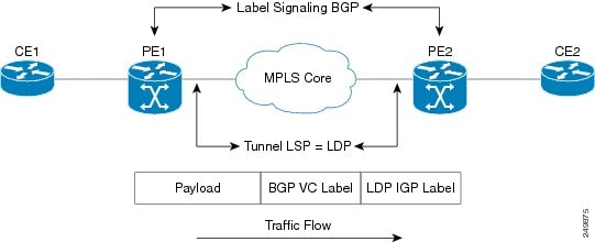
Figure 2. VPLS Autodiscovery and Signaling

BGP-based VPLS Autodiscovery

An important aspect of VPN technologies, including VPLS, is the ability of network devices to automatically signal to other devices about an association with a particular VPN. Autodiscovery requires this information to be distributed to all members of a VPN. VPLS is a multipoint mechanism for which BGP is well suited.

BGP-based VPLS autodiscovery eliminates the need to manually provision VPLS neighbors. VPLS autodiscovery enables each VPLS PE router to discover the other provider edge (PE) routers that are part of the same VPLS domain. VPLS Autodiscovery also tracks when PE routers are added to or removed from the VPLS domain. When the discovery process is complete, each PE router has the information required to setup VPLS pseudowires (PWs).

Even when BGP autodiscovery is enabled, pseudowires can be manually configured for VPLS PE routers that are not participating in the autodiscovery process.

BGP Auto Discovery With BGP Signaling

The implementation of VPLS in a network requires the establishment of a full mesh of PWs between the provider edge (PE) routers. The PWs can be signaled using BGP signaling.
Figure 3. Discovery and Signaling Attributes

Discovery and Signaling Attributes

The BGP signaling and autodiscovery scheme has the following components:
  • A means for a PE to learn which remote PEs are members of a given VPLS. This process is known as autodiscovery.

  • A means for a PE to learn the pseudowire label expected by a given remote PE for a given VPLS. This process is known as signaling.

The BGP Network Layer Reachability Information (NLRI) takes care of the above two components simultaneously. The NLRI generated by a given PE contains the necessary information required by any other PE. These components enable the automatic setting up of a full mesh of pseudowires for each VPLS without having to manually configure those pseudowires on each PE.

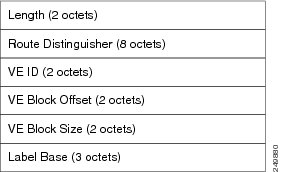
NLRI Format for VPLS with BGP AD and Signaling
The following figure shows the NLRI format for VPLS with BGP AD and Signaling
Figure 4. NLRI Format

NLRI Format

BGP Auto Discovery With LDP Signaling

Signaling of pseudowires requires exchange of information between two endpoints. Label Distribution Protocol (LDP) is better suited for point-to-point signaling. The signaling of pseudowires between provider edge devices, uses targeted LDP sessions to exchange label values and attributes and to configure the pseudowires.

Figure 5. Discovery and Signaling Attributes

A PE router advertises an identifier through BGP for each VPLS. This identifier is unique within the VPLS instance and acts like a VPLS ID. The identifier enables the PE router receiving the BGP advertisement to identify the VPLS associated with the advertisement and import it to the correct VPLS instance. In this manner, for each VPLS, a PE router learns the other PE routers that are members of the VPLS.

The LDP protocol is used to configure a pseudowire to all the other PE routers. FEC 129 is used for the signaling. The information carried by FEC 129 includes the VPLS ID, the Target Attachment Individual Identifier (TAII) and the Source Attachment Individual Identifier (SAII).

The LDP advertisement also contains the inner label or VPLS label that is expected for the incoming traffic over the pseudowire. This enables the LDP peer to identify the VPLS instance with which the pseudowire is to be associated and the label value that it is expected to use when sending traffic on that pseudowire.

NLRI and Extended Communities

The following figure depicts Network Layer Reachability Information (NLRI) and extended communities (Ext Comms).

Figure 6. NLRI and Extended Communities

Service Path Preference for L2VPN

Service Path Preference feature (SPP) helps control transport path for L2VPN services in traffic engineering (TE) tunnels. SPP feature provides a way for services to influence path selection while forwarding in Multiprotocol Label Switching (MPLS) networks. SPP is achieved by associating a control plane policy with a forward-class. SPP is supported for per-service path selection for VPLS with BGP AD, and EVI for PBB-EVPN and EVPN.

SPP for L2VPN is implemented in two steps:

  • Path selection - classify incoming traffic on a per service basis.

  • Path setup - set up paths with forward-class service.

Refer to Service Path Preference for MPLS VPN Sessions module for more information on SPP.

Understanding How Service Path Preference Works

SPP allows services to select a path based on policies configured in the control plane.

Consider a scenario where you have two Provider Edge (PE) routers in a setup. PE1 functions as ingress node and PE2 functions as egress node.

Figure 7. Sample Service Path Preference scenario


The ingress PE (PE1) receives the routes from the customers. The local policies determine the attribute to be assigned to the customer. PE1 associates a forward-class to the prefix based on the local policies that are created based on the VFI or EVI service. The pre-configured tunnel with matching forward-class is selected for forwarding the traffic.

L2VPN Route Policy

L2VPN route-policy feature enables the export community configuration for L2VPN VPWS and L2VPN VPLS with BGP autodiscovery. BGP executes the route-policy. This functionality is similar to the route-policy support under BGP submode for L3VPN services.

The following points explain the L2VPN route-policy functionality:
  1. The RPL is used to set standard community as policy action for two new attachpoints that are L2VPN export VPLS (VFI) and L2VPN export VPWS (MP2MP).

  2. L2VPN configuration specifies which route-policy to use for a given bridge-domain configured with BGP autodiscovery.

  3. L2VPN sends the route-policy name to BGP along with the L2VPN context.

  4. BGP process inserts standard community to the L2 NLRI.

Interoperability Between Cisco IOS XR and Cisco IOS on VPLS LDP Signaling

The Cisco IOS Software encodes the NLRI length in the fist byte in bits format in the BGP Update message. However, the Cisco IOS XR Software interprets the NLRI length in 2 bytes. Therefore, when the BGP neighbor with VPLS-VPWS address family is configured between the IOS and the IOS XR, NLRI mismatch can happen, leading to flapping between neighbors. To avoid this conflict, IOS supports prefix-length-size 2 command that needs to be enabled for IOS to work with IOS XR. When the prefix-length-size 2 command is configured in IOS, the NLRI length is encoded in bytes. This configuration is mandatory for IOS to work with IOS XR.

This is a sample IOS configuration with the prefix-length-size 2 command:


router bgp 1
 address-family l2vpn vpls
  neighbor 5.5.5.2 activate
  neighbor 5.5.5.2 prefix-length-size 2 --------> NLRI length = 2 bytes
 exit-address-family

MAC Address-related Parameters

The MAC address table contains a list of the known MAC addresses and their forwarding information. In the current VPLS design, the MAC address table and its management are maintained on the route processor (RP) card.

These topics provide information about the MAC address-related parameters:


Note

After you modify the MAC limit or action at the bridge domain level, ensure that you shut and unshut the bridge domain for the action to take effect. If you modify the MAC limit or action on an attachment circuit (through which traffic is passing), the attachment circuit must be shut and unshut for the action to take effect.

MAC Address Flooding

Ethernet services require that frames that are sent to broadcast addresses and to unknown destination addresses be flooded to all ports. To obtain flooding within VPLS broadcast models, all unknown unicast, broadcast, and multicast frames are flooded over the corresponding pseudowires and to all attachment circuits. Therefore, a PE must replicate packets across both attachment circuits and pseudowires.

MAC Address-based Forwarding

To forward a frame, a PE must associate a destination MAC address with a pseudowire or attachment circuit. This type of association is provided through a static configuration on each PE or through dynamic learning, which is flooded to all bridge ports.


Note

Split horizon forwarding applies in this case, for example, frames that are coming in on an attachment circuit or pseudowire are sent out of the same pseudowire. The pseudowire frames, which are received on one pseudowire, are not replicated on other pseudowires in the same virtual forwarding instance (VFI).

MAC Address Source-based Learning

When a frame arrives on a bridge port (for example, pseudowire or attachment circuit) and the source MAC address is unknown to the receiving PE router, the source MAC address is associated with the pseudowire or attachment circuit. Outbound frames to the MAC address are forwarded to the appropriate pseudowire or attachment circuit.

MAC address source-based learning uses the MAC address information that is learned in the hardware forwarding path. The updated MAC tables are propagated and programs the hardware for the router.


Note

Static MAC move is not supported from one port, interface, or AC to another port, interface, or AC. For example, if a static MAC is configured on AC1 (port 1) and then, if you send a packet with the same MAC as source MAC on AC2 (port 2), then you can’t attach this MAC to AC2 as a dynamic MAC. Therefore, do not send any packet with a MAC as any of the static MAC addresses configured.


The number of learned MAC addresses is limited through configurable per-port and per-bridge domain MAC address limits.

MAC Address Aging

A MAC address in the MAC table is considered valid only for the duration of the MAC address aging time. When the time expires, the relevant MAC entries are repopulated. When the MAC aging time is configured only under a bridge domain, all the pseudowires and attachment circuits in the bridge domain use that configured MAC aging time.

A bridge forwards, floods, or drops packets based on the bridge table. The bridge table maintains both static entries and dynamic entries. Static entries are entered by the network manager or by the bridge itself. Dynamic entries are entered by the bridge learning process. A dynamic entry is automatically removed after a specified length of time, known as aging time, from the time the entry was created or last updated.

If hosts on a bridged network are likely to move, decrease the aging-time to enable the bridge to adapt to the change quickly. If hosts do not transmit continuously, increase the aging time to record the dynamic entries for a longer time, thus reducing the possibility of flooding when the hosts transmit again.

MAC Address Limit

The MAC address limit is used to limit the number of learned MAC addresses. The bridge domain level limit is always configured and cannot be disabled. The default value of the bridge domain level limit is 4000 and can be changed in the range of 1-512000.

When a limit is exceeded, the system is configured to perform these notifications:

  • Syslog (default)

  • Simple Network Management Protocol (SNMP) trap

  • Syslog and SNMP trap

  • None (no notification)

MAC Address Withdrawal

For faster VPLS convergence, you can remove or unlearn the MAC addresses that are learned dynamically. The Label Distribution Protocol (LDP) Address Withdrawal message is sent with the list of MAC addresses, which need to be withdrawn to all other PEs that are participating in the corresponding VPLS service.

For the Cisco IOS XR VPLS implementation, a portion of the dynamically learned MAC addresses are cleared by using the MAC addresses aging mechanism by default. The MAC address withdrawal feature is added through the LDP Address Withdrawal message. To enable the MAC address withdrawal feature, use the withdrawal command in l2vpn bridge group bridge domain MAC configuration mode. To verify that the MAC address withdrawal is enabled, use the show l2vpn bridge-domain command with the detail keyword.


Note

By default, the LDP MAC Withdrawal feature is enabled on Cisco IOS XR.


The LDP MAC Withdrawal feature is generated due to these events:

  • Attachment circuit goes down. You can remove or add the attachment circuit through the CLI.

  • MAC withdrawal messages are received over a VFI pseudowire. RFC 4762 specifies that both wildcards (by means of an empty Type, Length and Value [TLV]) and a specific MAC address withdrawal. Cisco IOS XR software supports only a wildcard MAC address withdrawal.

MAC Address Security

You can configure MAC address security at the interfaces and at the bridge access ports (subinterfaces) levels. However, MAC security configured under an interface takes precedence to MAC security configured at the bridge domain level. When a MAC address is first learned, on an EFP that is configured with MAC security and then, the same MAC address is learned on another EFP, these events occur:

  • the packet is dropped

  • the second EFP is shutdown

  • the packet is learned and the MAC from the original EFP is flushed

MAC Address Move and Unicast Traffic Counters

MAC Address Move and Unicast Traffic counters are introduced on the VPLS bridge ports on the ASR9K platform. These counters essentially are L2VPN bridge port stats counters. MAC move and unicast traffic counters are introduced for troubleshooting. Cisco ASR 9000 High Density 100GE Ethernet Line Cards and Cisco ASR 9000 Enhanced Ethernet Line Cards support these counters.

For more information, on MAC Move and Unicast Traffic counters, use the show l2vpn bridge-domain command with the detail keyword on an AC Bridge, PW Bridge, PBB Edge, and VXLAN Bridge Ports.


Note

If the bridge port traffic is forwarded, either completely or partially to ASR 9000 Ethernet line cards, MAC Address Move and Unicast Traffic counters may not be accurate.


LSP Ping over VPWS and VPLS

For Cisco IOS XR software, the existing support for the Label Switched Path (LSP) ping and traceroute verification mechanisms for point-to-point pseudowires (signaled using LDP FEC128) is extended to cover the pseudowires that are associated with the VFI (VPLS). Currently, the support for the LSP ping and traceroute for LDP signalled FEC128 pseudowires is limited to manually configured VPLS pseudowires. In addition, Cisco IOS XR software supports LSP ping for point-to-point single-segment pseudowires that are signalled using LDP FEC129 AII-type 2 applicable to VPWS or signalled using LDP FEC129 AII-type 1 applicable to VPLS. For information about Virtual Circuit Connection Verification (VCCV) support and the ping mpls pseudowire command, see the MPLS Command Reference for Cisco ASR 9000 Series Routers.

Split Horizon Groups

An IOS XR bridge domain aggregates attachment circuits (ACs) and pseudowires (PWs) in one of three groups called Split Horizon Groups. When applied to bridge domains, Split Horizon refers to the flooding and forwarding behavior between members of a Split Horizon group. The following table describes how frames received on one member of a split horizon group are treated and if the traffic is forwarded out to the other members of the same split horizon group.

Bridge Domain traffic is either unicast or multicast.

Flooding traffic consists of unknown unicast destination MAC address frames; frames sent to Ethernet multicast addresses (Spanning Tree BPDUs, etc.); Ethernet broadcast frames (MAC address FF-FF-FF-FF-FF-FF).

Known Unicast traffic consists of frames sent to bridge ports that were learned from that port using MAC learning.

Traffic flooding is performed for broadcast, multicast and unknown unicast destination address.

Table 1. Split Horizon Groups Supported in Cisco IOS-XR
Split Horizon Group Who belongs to this Group? Multicast within Group Unicast within Group
0 Default—any member not covered by groups 1 or 2. Yes Yes
1 Any PW configured under VFI. No No
2 Any AC or PW configured with split-horizon keyword. No No

Important notes on Split Horizon Groups:

  • All bridge ports or PWs that are members of a bridge domain must belong to one of the three groups.

  • By default, all bridge ports or PWs are members of group 0.

  • The VFI configuration submode under a bridge domain configuration indicates that members under this domain are included in group 1.

  • A PW that is configured in group 0 is called an Access Pseudowire.

  • The split-horizon group command is used to designate bridge ports or PWs as members of group 2.

  • The ASR9000 only supports one VFI group.

Layer 2 Security

These topics describe the Layer 2 VPN extensions to support Layer 2 security:

Port Security

Use port security with dynamically learned and static MAC addresses to restrict a port’s ingress traffic by limiting the MAC addresses that are allowed to send traffic into the port. When secure MAC addresses are assigned to a secure port, the port does not forward ingress traffic that has source addresses outside the group of defined addresses. If the number of secure MAC addresses is limited to one and assigned a single secure MAC address, the device attached to that port has the full bandwidth of the port.

These port security features are supported:
  • Limits the MAC table size on a bridge or a port.

  • Facilitates actions and notifications for a MAC address.

  • Enables the MAC aging time and mode for a bridge or a port.

  • Filters static MAC addresses on a bridge or a port.

  • Marks ports as either secure or nonsecure.

  • Enables or disables flooding on a bridge or a port.

After you have set the maximum number of secure MAC addresses on a port, you can configure port security to include the secure addresses in the address table in one of these ways:
  • Statically configure all secure MAC addresses by using the static-address command.

  • Allow the port to dynamically configure secure MAC addresses with the MAC addresses of connected devices.

  • Statically configure a number of addresses and allow the rest to be dynamically configured.

Dynamic Host Configuration Protocol Snooping

Dynamic Host Configuration Protocol (DHCP) snooping is a security feature that acts like a firewall between untrusted hosts and trusted DHCP servers. The DHCP snooping feature performs these activities:

  • Validates DHCP messages received from untrusted sources and filters out invalid messages.

  • Rate-limits DHCP traffic from trusted and untrusted sources.

  • Builds and maintains the binding database of DHCP snooping, which contains information about untrusted hosts with leased IP addresses.

  • Utilizes the binding database of DHCP snooping to validate subsequent requests from untrusted hosts.

For additional information regarding DHCP, see the Cisco ASR 9000 Series Aggregation Services Router IP Addresses and Services Configuration Guide.

G.8032 Ethernet Ring Protection

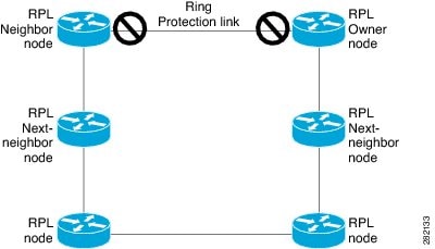
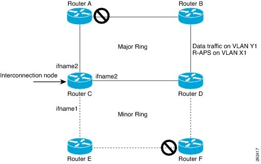
Ethernet Ring Protection (ERP) protocol, defined in ITU-T G.8032, provides protection for Ethernet traffic in a ring topology, while ensuring that there are no loops within the ring at the Ethernet layer. The loops are prevented by blocking either a pre-determined link or a failed link.

Overview

Each Ethernet ring node is connected to adjacent Ethernet ring nodes participating in the Ethernet ring using two independent links. A ring link never allows formation of loops that affect the network. The Ethernet ring uses a specific link to protect the entire Ethernet ring. This specific link is called the ring protection link (RPL). A ring link is bound by two adjacent Ethernet ring nodes and a port for a ring link (also known as a ring port).

Note

The minimum number of Ethernet ring nodes in an Ethernet ring is two.

The fundamentals of ring protection switching are:

  • the principle of loop avoidance

  • the utilization of learning, forwarding, and Filtering Database (FDB) mechanisms

Loop avoidance in an Ethernet ring is achieved by ensuring that, at any time, traffic flows on all but one of the ring links which is the RPL. Multiple nodes are used to form a ring:
  • RPL owner—It is responsible for blocking traffic over the RPL so that no loops are formed in the Ethernet traffic. There can be only one RPL owner in a ring.

  • RPL neighbor node—The RPL neighbor node is an Ethernet ring node adjacent to the RPL. It is responsible for blocking its end of the RPL under normal conditions. This node type is optional and prevents RPL usage when protected.

  • RPL next-neighbor node—The RPL next-neighbor node is an Ethernet ring node adjacent to RPL owner node or RPL neighbor node. It is mainly used for FDB flush optimization on the ring. This node is also optional.

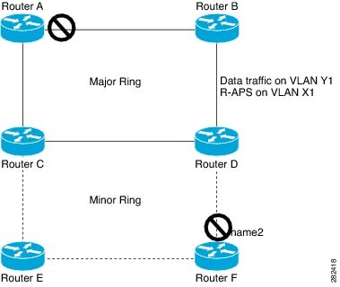
The following figure illustrates the G.8032 Ethernet ring.
Figure 8. G.8032 Ethernet Ring

G.8032 Ethernet Ring

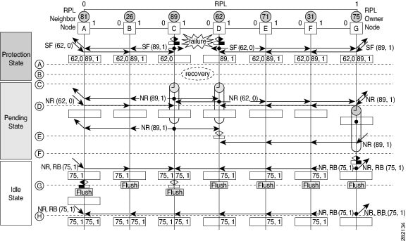
Nodes on the ring use control messages called RAPS to coordinate the activities of switching on or off the RPL link. Any failure along the ring triggers a RAPS signal fail (RAPS SF) message along both directions, from the nodes adjacent to the failed link, after the nodes have blocked the port facing the failed link. On obtaining this message, the RPL owner unblocks the RPL port.

Note

A single link failure in the ring ensures a loop-free topology.

Line status and Connectivity Fault Management protocols are used to detect ring link and node failure. During the recovery phase, when the failed link is restored, the nodes adjacent to the restored link send RAPS no request (RAPS NR) messages. On obtaining this message, the RPL owner blocks the RPL port and sends RAPS no request, root blocked (RAPS NR, RB) messages. This causes all other nodes, other than the RPL owner in the ring, to unblock all blocked ports. The ERP protocol is robust enough to work for both unidirectional failure and multiple link failure scenarios in a ring topology.

A G.8032 ring supports these basic operator administrative commands:
  • Force switch (FS)—Allows operator to forcefully block a particular ring-port.
    • Effective even if there is an existing SF condition

    • Multiple FS commands for ring supported

    • May be used to allow immediate maintenance operations

  • Manual switch (MS)—Allows operator to manually block a particular ring-port.

    • Ineffective in an existing FS or SF condition

    • Overridden by new FS or SF conditions

    • Multiple MS commands cancel all MS commands

  • Clear—Cancels an existing FS or MS command on the ring-port

    • Used (at RPL Owner) to clear non-revertive mode

A G.8032 ring can support multiple instances. An instance is a logical ring running over a physical ring. Such instances are used for various reasons, such as load balancing VLANs over a ring. For example, odd VLANs may go in one direction of the ring, and even VLANs may go in the other direction. Specific VLANs can be configured under only one instance. They cannot overlap multiple instances. Otherwise, data traffic or RAPS packet can cross logical rings, and that is not desirable.

G.8032 ERP provides a new technology that relies on line status and Connectivity Fault Management (CFM) to detect link failure. By running CFM Continuity Check Messages (CCM) messages at an interval of 100ms, it is possible to achieve SONET-like switching time performance and loop free traffic.

For more information about Ethernet Connectivity Fault Management (CFM) and Ethernet Fault Detection (EFD) configuration, refer to the Configuring Ethernet OAM on the Cisco ASR 9000 Series Router module in the Cisco ASR 9000 Series Aggregation Services Router Interface and Hardware Component Configuration Guide.

Timers

G.8032 ERP specifies the use of different timers to avoid race conditions and unnecessary switching operations:

  • Delay Timers—used by the RPL Owner to verify that the network has stabilized before blocking the RPL

    • After SF condition, Wait-to-Restore (WTR) timer is used to verify that SF is not intermittent. The WTR timer can be configured by the operator, and the default time interval is 5 minutes. The time interval ranges from 1 to 12 minutes.

    • After FS/MS command, Wait-to-Block timer is used to verify that no background condition exists.


    Note

    Wait-to-Block timer may be shorter than the Wait-to-Restore timer
  • Guard Timer—used by all nodes when changing state; it blocks latent outdated messages from causing unnecessary state changes. The Guard timer can be configured and the default time interval is 500 ms. The time interval ranges from 10 to 2000 ms.

  • Hold-off timers—used by underlying Ethernet layer to filter out intermittent link faults. The hold-off timer can be configured and the default time interval is 0 seconds. The time interval ranges from 0 to 10 seconds.

    • Faults are reported to the ring protection mechanism, only if this timer expires.

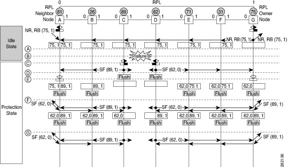
Single Link Failure

The following figure represents protection switching in case of a single link failure.

Figure 9. G.8032 Single Link Failure

G.8032 Single Link Failure

The following figure represents an Ethernet ring composed of seven Ethernet ring nodes. The RPL is the ring link between Ethernet ring nodes A and G. In these scenarios, both ends of the RPL are blocked. Ethernet ring node G is the RPL owner node, and Ethernet ring node A is the RPL neighbor node.

These symbols are used:


This sequence describes the steps in the single link failure, represented in Figure 8:

  1. Link operates in the normal condition.

  2. A failure occurs.

  3. Ethernet ring nodes C and D detect a local Signal Failure condition and after the holdoff time interval, block the failed ring port and perform the FDB flush.

  4. Ethernet ring nodes C and D start sending RAPS (SF) messages periodically along with the (Node ID, BPR) pair on both ring ports, while the SF condition persists.

  5. All Ethernet ring nodes receiving an RAPS (SF) message perform FDB flush. When the RPL owner node G and RPL neighbor node A receive an RAPS (SF) message, the Ethernet ring node unblocks it’s end of the RPL and performs the FDB flush.

  6. All Ethernet ring nodes receiving a second RAPS (SF) message perform the FDB flush again; this is because of the Node ID and BPR-based mechanism.

  7. Stable SF condition—RAPS (SF) messages on the Ethernet Ring. Further RAPS (SF) messages trigger no further action.

The following figure represents reversion in case of a single link failure.

Figure 10. Single link failure Recovery (Revertive operation)

Single link failure Recovery (Revertive operation)

This sequence describes the steps in the single link failure recovery, as represented in Figure 9:

  1. Link operates in the stable SF condition.
  2. Recovery of link failure occurs.

  3. Ethernet ring nodes C and D detect clearing of signal failure (SF) condition, start the guard timer and initiate periodical transmission of RAPS (NR) messages on both ring ports. (The guard timer prevents the reception of RAPS messages).

  4. When the Ethernet ring nodes receive an RAPS (NR) message, the Node ID and BPR pair of a receiving ring port is deleted and the RPL owner node starts the WTR timer.

  5. When the guard timer expires on Ethernet ring nodes C and D, they may accept the new RAPS messages that they receive. Ethernet ring node D receives an RAPS (NR) message with higher Node ID from Ethernet ring node C, and unblocks its non-failed ring port.

  6. When WTR timer expires, the RPL owner node blocks its end of the RPL, sends RAPS (NR, RB) message with the (Node ID, BPR) pair, and performs the FDB flush.

  7. When Ethernet ring node C receives an RAPS (NR, RB) message, it removes the block on its blocked ring ports, and stops sending RAPS (NR) messages. On the other hand, when the RPL neighbor node A receives an RAPS (NR, RB) message, it blocks its end of the RPL. In addition to this, Ethernet ring nodes A to F perform the FDB flush when receiving an RAPS (NR, RB) message, due to the existence of the Node ID and BPR based mechanism.

Flow Aware Transport Pseudowire (FAT PW)

Routers typically loadbalance traffic based on the lower most label in the label stack which is the same label for all flows on a given pseudowire. This can lead to asymmetric loadbalancing. The flow, in this context, refers to a sequence of packets that have the same source and destination pair. The packets are transported from a source provider edge (PE) to a destination PE.

Flow-Aware Transport Pseudowires (FAT PW) provide the capability to identify individual flows within a pseudowire and provide routers the ability to use these flows to loadbalance traffic. FAT PWs are used to loadbalance traffic in the core when equal cost multipaths (ECMP) are used. A flow label is created based on indivisible packet flows entering a pseudowire; and is inserted as the lower most label in the packet. Routers can use the flow label for loadbalancing which provides a better traffic distribution across ECMP paths or link-bundled paths in the core.

The following figure shows a FAT PW with two flows distributing over ECMPs and bundle links.

Figure 11. FAT PW with two flows distributing over ECMPs and Bundle-Links

An additional label is added to the stack, called the flow label, which contains the flow information of a virtual circuit (VC). A flow label is a unique identifier that distinguishes a flow within the PW, and is derived from source and destination MAC addresses, and source and destination IP addresses. The flow label contains the end of label stack (EOS) bit set and inserted after the VC label and before the control word (if any). The ingress PE calculates and forwards the flow label. The FAT PW configuration enables the flow label. The egress PE discards the flow label such that no decisions are made.

All core routers perform load balancing based on the flow-label in the FAT PW. Therefore, it is possible to distribute flows over ECMPs and link bundles.

You cannot send MPLS OAM ping traffic over a FAT PW, since there is no flow label support for MPLS OAM.

Pseudowire Headend

Pseudowires (PWs) enable payloads to be transparently carried across IP/MPLS packet-switched networks (PSNs). PWs are regarded as simple and manageable lightweight tunnels for returning customer traffic into core networks. Service providers are now extending PW connectivity into the access and aggregation regions of their networks.

Pseudowire Headend (PWHE) is a technology that allows termination of access pseudowires (PWs) into a Layer 3 (VRF or global) domain or into a Layer 2 domain. PWs provide an easy and scalable mechanism for tunneling customer traffic into a common IP/MPLS network infrastructure. PWHE allows customers to provision features such as QOS access lists (ACL), L3VPN on a per PWHE interface basis, on a service Provider Edge (PE) router.


Note

Encapsulation default is not supported by PWHE.


PWHE cross-connects to a pseudowire neighbour, which is reachable through recursive as well as non-recursive prefix. The reachability through recursive prefix is through introduction of BGP RFC3107 support on the Cisco ASR 9000 Series Router. Consider the following network topology for an example scenario.
Figure 12. Pseudowire Network


For PWHE x-connect configuration, interconnectivity between A-PE (Access Provider Edge) and S-PE is through BGP RFC3107 that distributes MPLS labels along with IP prefixes. The customer network can avoid using an IGP to provide connectivity to the S-PE device, which is outside the customer's autonomous system.

For all practical purposes, the PWHE interface is treated like any other existing L3 interface. PWs operate in one of the following modes:
  • Bridged interworking (VC type 5 or VC type 4)

  • IP interworking mode (VC type 11)

With VC type 4 and VC type 5, PWs carry customer Ethernet frames (tagged or untagged) with IP payload. Thus, an S-PE device must perform ARP resolution for customer IP addresses learned over the PWHE. With VC type 4 (VLAN tagged) and VC type 5 (Ethernet port/raw), PWHE acts as a broadcast interface. Whereas with VC type 11 (IP Interworking), PWHE acts as a point-to-point interface. Therefore there are two types of PWHE interface—PW-Ether (for VC type 4 and 5) and PW-IW (for VC type 11). These PWs can terminate into a VRF or the IP global table on S-PE.

Benefits of PWHE

Some of the benefits of implementing PWHE are:

  • dissociates the customer facing interface (CFI) of the service PE from the underlying physical transport media of the access or aggregation network

  • reduces capex in the access or aggregation network and service PE

  • distributes and scales the customer facing Layer 2 UNI interface set

  • implements a uniform method of OAM functionality

  • providers can extend or expand the Layer 3 service footprints

  • provides a method of terminating customer traffic into a next generation network (NGN)

Restrictions

  • FAT (flow-aware transport) labels or entropy labels are not supported on PWHE.

  • The system load balances PWHE based on PWID on the originating PE router over the interfaces in the generic interface list, and also on PWID on subsequent P routers.

  • PWHE is not supported over 2nd level BGP Labeled Unicast (LU) recursion.

Generic Interface List

A generic interface list contains is a list of physical or bundle interfaces that is used in a PW-HE connection.

The generic interface list supports only main interfaces, and not sub-interfaces. The generic interface list is bi-directional and restricts both receive and transmit interfaces on access-facing line cards. The generic interface list has no impact on the core-facing side.

A generic interface list is used to limit the resources allocated for a PWHE interface to the set of interfaces specified in the list.

Only the S-PE is aware of the generic interface list and expects that the PWHE packets arrive on only line cards with generic interface list members on it. If packets arrive at the line card without generic interface list members on it, they are dropped.

LFA over Pseudowire Headend

From Release 5.1.1, PW-HE is supported on loop free alternate (LFA) routes.

For LFA to be effective on a PW-HE interface, all the routing paths (protected and backup) must be included in the generic interface list of that PW-HE interface. If all the routing paths are not included in the generic interface list, then there may be loss of traffic even if LFA is enabled. This is because the LFA route could be the one that was not included in the generic interface list.

To configure LFA on PW-HE interface, do the following:

  1. Configuring Generic Interface List

  2. Configuring IP/LDP Fast Reroute

For more information about configuring the IP Fast Reroute Loop-free alternate, see Implementing IS-IS on Cisco IOS XR Software module of the Cisco ASR 9000 Series Aggregation Services Router Routing Configuration Guide.

PW-HE Multicast

Multicast support for Pseudowire Head-end (PW-HE) interfaces is available only on the enhanced ethernet cards.

For more information about PW-HE multicast feature, see the Implementing Layer 3 Multicast Routing chapter in the Cisco ASR 9000 Series Aggregation Services Router Multicast Configuration Guide, Release 5.1.x.

PW-HE over MPLS-TE Tunnels

The PW-HE over MPLS-TE Tunnels feature supports forwarding of pseudowire traffic (with pseudowire headend) over TE tunnels.

For more information about PW-HE over MPLS TE Tunnels, see the Implementing MPLS Traffic Engineering chapter in the Cisco ASR 9000 Series Aggregation Services Router MPLS Configuration Guide, Release 5.1.x.

L2VPN over GRE

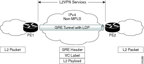
To transport an IP packet over a generic routing encapsulation (GRE) tunnel, the system first encapsulates the original IP packet with a GRE header. The encapsulated GRE packet is encapsulated once again by an outer transport header that is used to forward the packet to it’s destination. The following figure captures how GRE encapsulation over an IP transport network takes place.
Figure 13. GRE Encapsulation

GRE Encapsulation


Note

In the new IP packet, new payload is similar to the original IP packet. Additionally, the new IP header (New IP Hdr) is similar to the tunnel IP header which in turn is similar to the transport header.

When a GRE tunnel endpoint decapsulates a GRE packet, it further forwards the packet based on the payload type. For example, if the payload is a labeled packet then the packet is forwarded based on the virtual circuit (VC) label or the VPN label for L2VPN and L3VPN respectively.

L2VPN over GRE Restrictions

Some of the restrictions that you must consider while configuring L2VPN over GRE:

  • GRE over BVI is not supported.

  • For VPLS flow-based load balancing scenario, the GRE tunnel is pinned down to outgoing path based on tunnel source or destination cyclic redundancy check (CRC). Unicast and flood traffic always takes the same physical path for a given GRE tunnel.

  • Ingress attachment circuit must be an ASR 9000 Enhanced Ethernet Line Card for L2VPN over GRE. Additionally, GRE tunnel destination should be reachable only on an ASR 9000 Enhanced Ethernet Line Card.

  • The L2VPN over GRE feature is not supported on the ASR 9000 Ethernet Line Card or Cisco ASR 9000 Series SPA Interface Processor-700 line cards as the ingress attachment circuit and GRE destination is reachable over GRE.

  • Pseudowire over TE over GRE scenario is not supported.

  • Preferred Path Limitations:

    • When you configure GRE as a preferred path, egress features are not supported under the GRE tunnel (Egress ACL).

    • VCCV ping or traceroute are not supported for preferred path.

    • Preferred path is supported only for pseudowires configured in a provider egde (PE) to PE topology.

GRE Deployment Scenarios

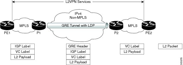
In an L2VPN network, you can deploy GRE in the following scenarios:

  • Configuring GRE tunnel between provider edge (PE) to PE routers

  • Configuring GRE tunnel between P to P routers

  • Configuring GRE tunnel between P to PE routers

The following diagrams depict the various scenarios:
Figure 14. GRE tunnel configured between PE to PE routers

GRE tunnel configured between PE to PE routers

Figure 15. GRE tunnel configured between P to P routers

GRE tunnel configured between P to P routers

Figure 16. GRE tunnel configured between P to PE routers

Note

These deployment scenarios are applicable to VPWS and VPLS.

GRE Tunnel as Preferred Path

Preferred tunnel path feature allows you to map pseudowires to specific GRE tunnels. Attachment circuits are cross-connected to GRE tunnel interfaces instead of remote PE router IP addresses (reachable using IGP or LDP). Using preferred tunnel path, it is always assumed that the GRE tunnel that transports the L2 traffic runs between the two PE routers (that is, its head starts at the imposition PE router and terminates on the disposition PE router).

Multipoint Layer 2 Services Label Switched Multicast

Multipoint Layer 2 Services Label Switched Multicast (LSM) is a Layer 2 based solution that sends multicast traffic over a multiprotocol label switching (MPLS) network. In Multipoint Layer 2 Services, point-to-point (P2P) pseudowires (PWs) are setup at PE routers participating in a Multipoint Layer 2 Services domain, to provide Ethernet LAN emulation. Broadcast, multicast and unknown unicast traffic can be sent through ingress replicaton or label switched multicast in the Multipoint Layer 2 Services domain.

Ingress Replication and its Limitations

In ingress replication, broadcast, multicast and unknown unicast traffic are replicated at the ingress PE router. Individual copies of the same packets are sent to remote PE routers that participate in the same VPLS domain. However, ingress replication has these limitations:

  • Results in significant waste of link bandwidth when there is heavy broadcast and multicast VPLS traffic

  • Is resource intensive because the ingress PE router is most impacted by the replication

VPLS LSM as a Solution

VPLS Label Switched Multicast (LSM) is an effective multicast solution for overcoming the limitations of ingress replication. This solution employs point-to-multipoint (P2MP) label switched path (LSP) in the MPLS network to transport multicast traffic over a VPLS domain.


Note

Only broadcast, multicast or unknown unicast traffic is sent over P2MP LSPs

The VPLS LSM solution supports BGP based P2MP PW signaling. As a result, remote PEs participating in the VPLS domain are discovered automatically using the BGP autodiscovery mechanism. Creating a P2MP PW for each VPLS domain allows emulating VPLS P2MP service for PWs in the VPLS domain.

Multicast trees used for VPLS can be of two types:

  • Inclusive trees

  • Selective trees

Inclusive trees—This option supports the use of a single multicast distribution tree in the SP network to carry all the multicast traffic from a specified set of VPLS sites connected to a given PE. A particular multicast tree can be set up to carry the traffic originated by sites belonging to a single VPLS instance, or belonging to different VPLS instances. The ability to carry the traffic of more than one VPLS instance on the same tree is called Aggregate Inclusive. The tree needs to include every PE that is a member of any of the VPLS instances that are using the tree. A PE may receive multicast traffic for a multicast stream even if it doesn't have any receivers that are interested in receiving traffic for that stream. An Inclusive multicast tree in VPLS LSM is a P2MP tree.

Selective trees—A Selective multicast tree is used by a PE to send IP multicast traffic for one or more specific IP multicast streams, received by the PE over PE-CE interfaces that belong to the same or different VPLS instances, to a subset of the PEs that belong to those VPLS instances. This is to provide a PE the ability to create separate SP multicast trees for specific multicast streams, e.g. high bandwidth multicast streams. This allows traffic for these multicast streams to reach only those PE routers that have receivers for these streams. This avoids flooding other PE routers in the VPLS instance.

VPLS LSM Limitations

VPLS LSM has these limitations:

  • Only BGP-AD signaling with RSVP-TE multicast trees are supported.

  • Statically configured PWs are not supported.

  • Only Inclusive trees are supported.

  • Selective multicast trees are not supported.

  • LDP signalled P2P PW is not supported. Only BGP signalled PWs are supported.

  • Only RSVP-TE multicast trees are supported.

  • If IGMP snooping is enabled in a bridge domain participating in the P2MP multicast tree root, IGMP snooping traffic is forwarded using ingress replication. P2MP multicast trees are not used.

  • P2MP PW signaling is initiated when P2MP is enabled in a VPLS domain. Therefore, it is possible that one or more Leaf PEs are unable to join the multicast tree. In this scenario, the leaf PEs do not receive traffic sent over the P2MP tree.

  • Traffic is silently dropped until the Leaf PEs join the multicast tree successfully. Automatic recovery is not supported.

  • MAC learning occurs when unknown unicast traffic is sent on a P2MP multicast tree. As a result, traffic is switched to a P2P PW. Packet reordering may occur as P2P and P2MP PWs potentially take different paths through the network. Traffic, which is already in transit over P2MP, may arrive later than newer traffic on P2P PW for the same flow.

  • With respect to VPLS LSM, the A9K-SIP-700 Line Card has some specific limitations as follows:
    • ISSU is not supported.

    • QoS is not supported on Access-PW on this line card.

    • MPLS-TE is not supported on serial interfaces.

    • If TE or RSVP or both are configured, RSVP does not remove the interface and neighbors.

    • Only FRR Link Protection is supported. FRR Node Protection is not supported.

    • The maximum number of P2MP-enabled BD-VFI supported is 1000.

    • To transition from Bud to Mid node, remove the entire l2vpn configuration using the no l2vpn command. Configuring no multicast p2mp command is not enough.

How to Implement Multipoint Layer 2 Services

This section describes the tasks that are required to implement Multipoint Layer 2 Services:

Configuring a Bridge Domain

These topics describe how to configure a bridge domain:

Creating a Bridge Domain

Perform this task to create a bridge domain .

SUMMARY STEPS

  1. configure
  2. l2vpn
  3. bridge group bridge-group-name
  4. bridge-domain bridge-domain-name
  5. Use the commit or end command.

DETAILED STEPS


Step 1

configure

Example:
RP/0/RSP0/CPU0:router# configure

Enters the Global Configuration mode.

Step 2

l2vpn

Example:

RP/0/RSP0/CPU0:router(config)# l2vpn
RP/0/RSP0/CPU0:router(config-l2vpn)#

Enters L2VPN configuration mode.

Step 3

bridge group bridge-group-name

Example:

RP/0/RSP0/CPU0:router(config-l2vpn)# bridge group csco
RP/0/RSP0/CPU0:router(config-l2vpn-bg)#

Creates a bridge group that can contain bridge domains, and then assigns network interfaces to the bridge domain.

Step 4

bridge-domain bridge-domain-name

Example:

RP/0/RSP0/CPU0:router(config-l2vpn-bg)# bridge-domain abc
RP/0/RSP0/CPU0:router(config-l2vpn-bg-bd)#

Establishes a bridge domain and enters L2VPN bridge group bridge domain configuration mode.

Step 5

Use the commit or end command.

commit - Saves the configuration changes and remains within the configuration session.

end - Prompts user to take one of these actions:

  • Yes - Saves configuration changes and exits the configuration session.
  • No - Exits the configuration session without committing the configuration changes.
  • Cancel - Remains in the configuration mode, without committing the configuration changes.

Configuring a Pseudowire

Perform this task to configure a pseudowire under a bridge domain.

SUMMARY STEPS

  1. configure
  2. l2vpn
  3. bridge group bridge group name
  4. bridge-domain bridge-domain name
  5. vfi { vfi-name }
  6. exit
  7. neighbor { A.B.C.D } { pw-id value }
  8. dhcp ipv4 snoop profile { dhcp_snoop_profile_name }
  9. Use the commit or end command.

DETAILED STEPS


Step 1

configure

Example:
RP/0/RSP0/CPU0:router# configure

Enters the Global Configuration mode.

Step 2

l2vpn

Example:

RP/0/RSP0/CPU0:router(config)# l2vpn
RP/0/RSP0/CPU0:router(config-l2vpn)#

Enters L2VPN configuration mode.

Step 3

bridge group bridge group name

Example:

RP/0/RSP0/CPU0:router(config-l2vpn)# bridge group csco
RP/0/RSP0/CPU0:router(config-l2vpn-bg)#

Creates a bridge group so that it can contain bridge domains and then assigns network interfaces to the bridge domain.

Step 4

bridge-domain bridge-domain name

Example:

RP/0/RSP0/CPU0:router(config-l2vpn-bg)# bridge-domain abc
RP/0/RSP0/CPU0:router(config-l2vpn-bg-bd)#

Establishes a bridge domain and enters L2VPN bridge group bridge domain configuration mode.

Step 5

vfi { vfi-name }

Example:

RP/0/RSP0/CPU0:router(config-l2vpn-bg-bd)# vfi v1
RP/0/RSP0/CPU0:router(config-l2vpn-bg-bd-vfi)#

Configures the virtual forwarding interface (VFI) parameters and enters L2VPN bridge group bridge domain VFI configuration mode.

  • Use the vfi-name argument to configure the name of the specified virtual forwarding interface.
Step 6

exit

Example:

RP/0/RSP0/CPU0:router(config-l2vpn-bg-bd-vfi)# exit
RP/0/RSP0/CPU0:router(config-l2vpn-bg-bd)#

Exits the current configuration mode.

Step 7

neighbor { A.B.C.D } { pw-id value }

Example:

RP/0/RSP0/CPU0:router(config-l2vpn-bg-bd)# neighbor 10.1.1.2 pw-id 1000
RP/0/RSP0/CPU0:router(config-l2vpn-bg-bd-pw)#

Adds an access pseudowire port to a bridge domain or a pseudowire to a bridge virtual forwarding interface (VFI).

  • Use the A.B.C.D argument to specify the IP address of the cross-connect peer.
  • Use the pw-id keyword to configure the pseudowire ID and ID value. The range is 1 to 4294967295.
Step 8

dhcp ipv4 snoop profile { dhcp_snoop_profile_name }

Example:

RP/0/RSP0/CPU0:router(config-l2vpn-bg-bd-pw)#dhcp ipv4 snoop profile profile1

Enables DHCP snooping on the bridge, and attaches a DHCP snooping profile.

Step 9

Use the commit or end command.

commit - Saves the configuration changes and remains within the configuration session.

end - Prompts user to take one of these actions:

  • Yes - Saves configuration changes and exits the configuration session.
  • No - Exits the configuration session without committing the configuration changes.
  • Cancel - Remains in the configuration mode, without committing the configuration changes.

Associating Members with a Bridge Domain

After a bridge domain is created, perform this task to assign interfaces to the bridge domain. These types of bridge ports are associated with a bridge domain:

  • Ethernet and VLAN

  • VFI

SUMMARY STEPS

  1. configure
  2. l2vpn
  3. bridge group bridge group name
  4. bridge-domain bridge-domain name
  5. interface type interface-path-id
  6. (Optional) static-mac-address { MAC-address }
  7. routed interface BVI-id
  8. Use the commit or end command.

DETAILED STEPS


Step 1

configure

Example:
RP/0/RSP0/CPU0:router# configure

Enters the Global Configuration mode.

Step 2

l2vpn

Example:
RP/0/RSP0/CPU0:router(config)# l2vpn

Enters L2VPN configuration mode.

Step 3

bridge group bridge group name

Example:

RP/0/RSP0/CPU0:router(config-l2vpn)# bridge group csco
RP/0/RSP0/CPU0:router(config-l2vpn-bg)#

Creates a bridge group so that it can contain bridge domains and then assigns network interfaces to the bridge domain.

Step 4

bridge-domain bridge-domain name

Example:

RP/0/RSP0/CPU0:router(config-l2vpn-bg)# bridge-domain abc
RP/0/RSP0/CPU0:router(config-l2vpn-bg-bd)#

Establishes a bridge domain and enters L2VPN bridge group bridge domain configuration mode.

Step 5

interface type interface-path-id

Example:

RP/0/RSP0/CPU0:router(config-l2vpn-bg-bd)# interface GigabitEthernet 0/4/0/0
RP/0/RSP0/CPU0:router(config-l2vpn-bg-bd-ac)#

Enters interface configuration mode and adds an interface to a bridge domain that allows packets to be forwarded and received from other interfaces that are part of the same bridge domain.

Step 6

(Optional) static-mac-address { MAC-address }

Example:

RP/0/RSP0/CPU0:router(config-l2vpn-bg-bd-ac)# static-mac-address 1.1.1
RP/0/RSP0/CPU0:router(config-l2vpn-bg-bd-ac)# exit
RP/0/RSP0/CPU0:router(config-l2vpn-bg-bd)# 

Configures the static MAC address to associate a remote MAC address with a pseudowire or any other bridge interface.

Step 7

routed interface BVI-id

Example:

RP/0/RSP0/CPU0:router(config-l2vpn-bg-bd)# routed interface BVI100
RP/0/RSP0/CPU0:router(config-l2vpn-bg-bd-ac)#

Perform this step if you need the VPLS pseudowire traffic routed over an Integrated Routing and Bridging (IRB). This command enters bridge-group virtual interface configuration mode and adds a bridge-group virtual interface (BVI) to the bridge domain that allows packets to be forwarded and received from other interfaces that are part of the same bridge domain. This step is essential to bring the BVI's status up.

Step 8

Use the commit or end command.

commit - Saves the configuration changes and remains within the configuration session.

end - Prompts user to take one of these actions:

  • Yes - Saves configuration changes and exits the configuration session.

  • No - Exits the configuration session without committing the configuration changes.

  • Cancel - Remains in the configuration mode, without committing the configuration changes.


Configuring Bridge Domain Parameters

To configure bridge domain parameters, associate these parameters with a bridge domain:

  • Maximum transmission unit (MTU)—Specifies that all members of a bridge domain have the same MTU. The bridge domain member with a different MTU size is not used by the bridge domain even though it is still associated with a bridge domain.

  • Flooding—Flooding is enabled always.

  • Dynamic ARP Inspection (DAI)—Ensures only valid ARP requests and responses are relayed.

  • IP SourceGuard (IPSG)—Enables source IP address filtering on a Layer 2 port.


Note

To verify if the DAI and IPSG features are working correctly, look up the packets dropped statistics for DAI and IPSG violation. The packet drops statistics can be viewed in the output of the show l2vpn bridge-domain bd-name <> detail command.

SUMMARY STEPS

  1. configure
  2. l2vpn
  3. bridge group bridge-group-name
  4. bridge-domain bridge-domain-name
  5. flooding disable
  6. mtu bytes
  7. dynamic-arp-inspection { address-validation | disable | logging }
  8. ip-source-guard logging
  9. Use the commit or end command.

DETAILED STEPS


Step 1

configure

Example:
RP/0/RSP0/CPU0:router# configure

Enters the Global Configuration mode.

Step 2

l2vpn

Example:

RP/0/RSP0/CPU0:router(config)# l2vpn
RP/0/RSP0/CPU0:router(config-l2vpn)#

Enters the l2vpn configuration mode.

Step 3

bridge group bridge-group-name

Example:

RP/0/RSP0/CPU0:router(config-l2vpn)# bridge group csco
RP/0/RSP0/CPU0:router(config-l2vpn-bg)#

Creates a bridge group so that it can contain bridge domains and then assigns network interfaces to the bridge domain.

Step 4

bridge-domain bridge-domain-name

Example:

RP/0/RSP0/CPU0:router(config-l2vpn-bg)# bridge-domain abc
RP/0/RSP0/CPU0:router(config-l2vpn-bg-bd)#

Establishes a bridge domain and enters l2vpn bridge group bridge domain configuration mode.

Step 5

flooding disable

Example:

RP/0/RSP0/CPU0:router(config-l2vpn-bg-bd)# flooding disable
RP/0/RSP0/CPU0:router(config-l2vpn-bg-bd)#

Disables flooding.

Step 6

mtu bytes

Example:

RP/0/RSP0/CPU0:router(config-l2vpn-bg-bd)# mtu 1000

Adjusts the maximum packet size or maximum transmission unit (MTU) size for the bridge domain.

  • Use the bytes argument to specify the MTU size, in bytes. The range is from 64 to 65535.

Step 7

dynamic-arp-inspection { address-validation | disable | logging }

Example:

RP/0/RSP0/CPU0:router(config-l2vpn-bg-bd)# dynamic-arp-inspection

Enters the dynamic ARP inspection configuration submode. Ensures only valid ARP requests and responses are relayed.

Note 
You can configure dynamic ARP inspection under the bridge domain or the bridge port.
Step 8

ip-source-guard logging

Example:

RP/0/RSP0/CPU0:router(config-l2vpn-bg-bd)# ip-source-guard logging

Enters the IP source guard configuration submode and enables source IP address filtering on a Layer 2 port.

You can enable IP source guard under the bridge domain or the bridge port. By default, bridge ports under a bridge inherit the IP source guard configuration from the parent bridge.

By default, IP source guard is disabled on the bridges.

Step 9

Use the commit or end command.

commit - Saves the configuration changes and remains within the configuration session.

end - Prompts user to take one of these actions:

  • Yes - Saves configuration changes and exits the configuration session.

  • No - Exits the configuration session without committing the configuration changes.

  • Cancel - Remains in the configuration mode, without committing the configuration changes.


Disabling a Bridge Domain

Perform this task to disable a bridge domain. When a bridge domain is disabled, all VFIs that are associated with the bridge domain are disabled. You are still able to attach or detach members to the bridge domain and the VFIs that are associated with the bridge domain.

SUMMARY STEPS

  1. configure
  2. l2vpn
  3. bridge group bridge group name
  4. bridge-domain bridge-domain name
  5. shutdown
  6. Use the commit or end command.

DETAILED STEPS


Step 1

configure

Example:
RP/0/RSP0/CPU0:router# configure

Enters the Global Configuration mode.

Step 2

l2vpn

Example:

RP/0/RSP0/CPU0:router(config)# l2vpn
RP/0/RSP0/CPU0:router(config-l2vpn)#

Enters L2VPN configuration mode.

Step 3

bridge group bridge group name

Example:

RP/0/RSP0/CPU0:router(config-l2vpn)# bridge group csco
RP/0/RSP0/CPU0:router(config-l2vpn-bg)#

Creates a bridge group so that it can contain bridge domains and then assigns network interfaces to the bridge domain.

Step 4

bridge-domain bridge-domain name

Example:

RP/0/RSP0/CPU0:router(config-l2vpn-bg)# bridge-domain abc
RP/0/RSP0/CPU0:router(config-l2vpn-bg-bd)#

Establishes a bridge domain and enters l2vpn bridge group bridge domain configuration mode.

Step 5

shutdown

Example:

RP/0/RSP0/CPU0:router(config-l2vpn-bg-bd)# shutdown

Shuts down a bridge domain to bring the bridge and all attachment circuits and pseudowires under it to admin down state.

Step 6

Use the commit or end command.

commit - Saves the configuration changes and remains within the configuration session.

end - Prompts user to take one of these actions:

  • Yes - Saves configuration changes and exits the configuration session.
  • No - Exits the configuration session without committing the configuration changes.
  • Cancel - Remains in the configuration mode, without committing the configuration changes.

Blocking Unknown Unicast Flooding

Perform this task to disable flooding of unknown unicast traffic at the bridge domain level.

You can disable flooding of unknown unicast traffic at the bridge domain, bridge port or access pseudowire levels. By default, unknown unicast traffic is flooded to all ports in the bridge domain.

Note

If you disable flooding of unknown unicast traffic on the bridge domain, all ports within the bridge domain inherit this configuration. You can configure the bridge ports to override the bridge domain configuration.

SUMMARY STEPS

  1. configure
  2. l2vpn
  3. bridge group bridge-group-name
  4. bridge-domain bridge-domain-name
  5. flooding unknown-unicast disable
  6. Use the commit or end command.

DETAILED STEPS


Step 1

configure

Example:
RP/0/RSP0/CPU0:router# configure

Enters the Global Configuration mode.

Step 2

l2vpn

Example:

RP/0/RSP0/CPU0:router(config)# l2vpn
RP/0/RSP0/CPU0:router(config-l2vpn)#

Enters L2VPN configuration mode.

Step 3

bridge group bridge-group-name

Example:
RP/0/RSP0/CPU0:router(config-l2vpn)# bridge group csco
RP/0/RSP0/CPU0:router(config-l2vpn-bg)#

Creates a bridge group so that it can contain bridge domains and then assigns network interfaces to the bridge domain.

Step 4

bridge-domain bridge-domain-name

Example:
RP/0/RSP0/CPU0:router(config-l2vpn-bg)# bridge-domain abc
RP/0/RSP0/CPU0:router(config-l2vpn-bg-bd)#

Establishes a bridge domain and enters l2vpn bridge group bridge domain configuration mode.

Step 5

flooding unknown-unicast disable

Example:
RP/0/RSP0/CPU0:router(config-l2vpn-bg-bd)#
flooding unknown-unicast disable

Disables flooding of unknown unicast traffic at the bridge domain level.

Step 6

Use the commit or end command.

commit - Saves the configuration changes and remains within the configuration session.

end - Prompts user to take one of these actions:

  • Yes - Saves configuration changes and exits the configuration session.
  • No - Exits the configuration session without committing the configuration changes.
  • Cancel - Remains in the configuration mode, without committing the configuration changes.

Changing the Flood Optimization Mode

Perform this task to change the flood optimization mode under the bridge domain:

SUMMARY STEPS

  1. configure
  2. l2vpn
  3. bridge group bridge-group-name
  4. bridge-domain bridge-domain-name
  5. flood mode convergence-optimized
  6. Use the commit or end command.

DETAILED STEPS


Step 1

configure

Example:
RP/0/RSP0/CPU0:router# configure

Enters the Global Configuration mode.

Step 2

l2vpn

Example:
RP/0/RSP0/CPU0:router(config)# l2vpn

Enters L2VPN configuration mode.

Step 3

bridge group bridge-group-name

Example:

RP/0/RSP0/CPU0:router(config-l2vpn)# bridge group csco
RP/0/RSP0/CPU0:router(config-l2vpn-bg)#

Creates a bridge group so that it can contain bridge domains and then assigns network interfaces to the bridge domain.

Step 4

bridge-domain bridge-domain-name

Example:

RP/0/RSP0/CPU0:router(config-l2vpn-bg)# bridge-domain abc
RP/0/RSP0/CPU0:router(config-l2vpn-bg-bd)#

Establishes a bridge domain and enters l2vpn bridge group bridge domain configuration mode.

Step 5

flood mode convergence-optimized

Example:

RP/0/RSP0/CPU0:router(config-l2vpn-bg-bd)# flood mode convergence-optimized

Changes the default flood optimization mode from Bandwidth Optimization Mode to Convergence Mode.

Step 6

Use the commit or end command.

commit - Saves the configuration changes and remains within the configuration session.

end - Prompts user to take one of these actions:

  • Yes - Saves configuration changes and exits the configuration session.
  • No - Exits the configuration session without committing the configuration changes.
  • Cancel - Remains in the configuration mode, without committing the configuration changes.

Configuring Layer 2 Security

These topics describe how to configure Layer 2 security:

Enabling Layer 2 Security

Perform this task to enable Layer 2 port security on a bridge.

SUMMARY STEPS

  1. configure
  2. l2vpn
  3. bridge group bridge-group-name
  4. bridge domain bridge-domain-name
  5. security
  6. Use the commit or end command.

DETAILED STEPS


Step 1

configure

Example:
RP/0/RSP0/CPU0:router# configure

Enters the Global Configuration mode.

Step 2

l2vpn

Example:

RP/0/RSP0/CPU0:router(config)# l2vpn
RP/0/RSP0/CPU0:router(config-l2vpn)#

Enters L2VPN configuration mode.

Step 3

bridge group bridge-group-name

Example:

RP/0/RSP0/CPU0:router(config-l2vpn)# bridge group csco
RP/0/RSP0/CPU0:router(config-l2vpn-bg)#

Assigns each network interface to a bridge group and enters L2VPN bridge group configuration mode.

Step 4

bridge domain bridge-domain-name

Example:

RP/0/RSP0/CPU0:router(config-l2vpn-bg)# bridge-domain abc
RP/0/RSP0/CPU0:router(config-l2vpn-bg-bd)#

Establishes a bridge domain and enters L2VPN bridge group bridge domain configuration mode.

Step 5

security

Example:

RP/0/RSP0/CPU0:router(config-l2vpn-bg-bd)# security

Enables Layer 2 port security on a bridge.

Step 6

Use the commit or end command.

commit - Saves the configuration changes and remains within the configuration session.

end - Prompts user to take one of these actions:

  • Yes - Saves configuration changes and exits the configuration session.
  • No - Exits the configuration session without committing the configuration changes.
  • Cancel - Remains in the configuration mode, without committing the configuration changes.

Attaching a Dynamic Host Configuration Protocol Profile

Perform this task to enable DHCP snooping on a bridge and to attach a DHCP snooping profile to a bridge.

SUMMARY STEPS

  1. configure
  2. l2vpn
  3. bridge group bridge-group-name
  4. bridge-domain bridge-domain-name
  5. dhcp ipv4 snoop { profile profile-name }
  6. Use the commit or end command.

DETAILED STEPS


Step 1

configure

Example:
RP/0/RSP0/CPU0:router# configure

Enters the Global Configuration mode.

Step 2

l2vpn

Example:

RP/0/RSP0/CPU0:router(config)# l2vpn
RP/0/RSP0/CPU0:router(config-l2vpn)#

Enters L2VPN configuration mode.

Step 3

bridge group bridge-group-name

Example:

RP/0/RSP0/CPU0:router(config-l2vpn)# bridge group csco
RP/0/RSP0/CPU0:router(config-l2vpn-bg)#

Assigns each network interface to a bridge group and enters L2VPN bridge group configuration mode.

Step 4

bridge-domain bridge-domain-name

Example:

RP/0/RSP0/CPU0:router(config-l2vpn-bg)# bridge-domain abc
RP/0/RSP0/CPU0:router(config-l2vpn-bg-bd)#

Establishes a bridge domain and enters L2VPN bridge group bridge domain configuration mode.

Step 5

dhcp ipv4 snoop { profile profile-name }

Example:

RP/0/RSP0/CPU0:router(config-l2vpn-bg-bd)# dhcp ipv4 snoop profile attach

Enables DHCP snooping on a bridge and attaches DHCP snooping profile to the bridge.

  • Use the profile keyword to attach a DHCP profile. The profile-name argument is the profile name for DHCPv4 snooping.

Step 6

Use the commit or end command.

commit - Saves the configuration changes and remains within the configuration session.

end - Prompts user to take one of these actions:

  • Yes - Saves configuration changes and exits the configuration session.
  • No - Exits the configuration session without committing the configuration changes.
  • Cancel - Remains in the configuration mode, without committing the configuration changes.

Configuring a Layer 2 Virtual Forwarding Instance

These topics describe how to configure a Layer 2 virtual forwarding instance (VFI):

Creating the Virtual Forwarding Instance

Perform this task to create a Layer 2 Virtual Forwarding Instance (VFI) on all provider edge devices under the bridge domain.

SUMMARY STEPS

  1. configure
  2. l2vpn
  3. bridge group bridge group name
  4. bridge-domain bridge-domain name
  5. vfi {vfi-name}
  6. Use the commit or end command.

DETAILED STEPS


Step 1

configure

Example:
RP/0/RSP0/CPU0:router# configure

Enters the Global Configuration mode.

Step 2

l2vpn

Example:

RP/0/RSP0/CPU0:router(config)# l2vpn
RP/0/RSP0/CPU0:router(config-l2vpn)#

Enters L2VPN configuration mode.

Step 3

bridge group bridge group name

Example:

RP/0/RSP0/CPU0:router(config-l2vpn)# bridge group csco
RP/0/RSP0/CPU0:router(config-l2vpn-bg)#

Creates a bridge group so that it can contain bridge domains and then assigns network interfaces to the bridge domain.

Step 4

bridge-domain bridge-domain name

Example:

RP/0/RSP0/CPU0:router(config-l2vpn-bg)# bridge-domain abc
RP/0/RSP0/CPU0:router(config-l2vpn-bg-bd)#

Establishes a bridge domain and enters L2VPN bridge group bridge domain configuration mode.

Step 5

vfi {vfi-name}

Example:

RP/0/RSP0/CPU0:router(config-l2vpn-bg-bd)# vfi v1
RP/0/RSP0/CPU0:router(config-l2vpn-bg-bd-vfi)#

Configures virtual forwarding interface (VFI) parameters and enters L2VPN bridge group bridge domain VFI configuration mode.

Step 6

Use the commit or end command.

commit - Saves the configuration changes and remains within the configuration session.

end - Prompts user to take one of these actions:

  • Yes - Saves configuration changes and exits the configuration session.
  • No - Exits the configuration session without committing the configuration changes.
  • Cancel - Remains in the configuration mode, without committing the configuration changes.

Associating Pseudowires with the Virtual Forwarding Instance

After a VFI is created, perform this task to associate one or more pseudowires with the VFI.

SUMMARY STEPS

  1. configure
  2. l2vpn
  3. bridge group bridge-group-name
  4. bridge-domain bridge-domain-name
  5. vfi { vfi name }
  6. neighbor { A.B.C.D } { pw-id value }
  7. Use the commit or end command.

DETAILED STEPS


Step 1

configure

Example:
RP/0/RSP0/CPU0:router# configure

Enters the Global Configuration mode.

Step 2

l2vpn

Example:

RP/0/RSP0/CPU0:router(config)# l2vpn
RP/0/RSP0/CPU0:router(config-l2vpn)#

Enters L2VPN configuration mode.

Step 3

bridge group bridge-group-name

Example:

RP/0/RSP0/CPU0:router(config-l2vpn)# bridge group csco
RP/0/RSP0/CPU0:router(config-l2vpn-bg)#

Creates a bridge group so that it can contain bridge domains and then assigns network interfaces to the bridge domain.

Step 4

bridge-domain bridge-domain-name

Example:

RP/0/RSP0/CPU0:router(config-l2vpn-bg)# bridge-domain abc
RP/0/RSP0/CPU0:router(config-l2vpn-bg-bd)#

Establishes a bridge domain and enters L2VPN bridge group bridge domain configuration mode.

Step 5

vfi { vfi name }

Example:

RP/0/RSP0/CPU0:router(config-l2vpn-bg-bd)# vfi v1
RP/0/RSP0/CPU0:router(config-l2vpn-bg-bd-vfi)#

Configures virtual forwarding interface (VFI) parameters and enters L2VPN bridge group bridge domain VFI configuration mode.

Step 6

neighbor { A.B.C.D } { pw-id value }

Example:

RP/0/RSP0/CPU0:router(config-l2vpn-bg-bd-vfi)# neighbor 10.1.1.2 pw-id 1000
RP/0/RSP0/CPU0:router(config-l2vpn-bg-bd-vfi-pw)#

Adds a pseudowire port to a bridge domain or a pseudowire to a bridge virtual forwarding interface (VFI).

  • Use the A.B.C.D argument to specify the IP address of the cross-connect peer.

  • Use the pw-id keyword to configure the pseudowire ID and ID value. The range is 1 to 4294967295.

Step 7

Use the commit or end command.

commit - Saves the configuration changes and remains within the configuration session.

end - Prompts user to take one of these actions:

  • Yes - Saves configuration changes and exits the configuration session.
  • No - Exits the configuration session without committing the configuration changes.
  • Cancel - Remains in the configuration mode, without committing the configuration changes.

Associating a Virtual Forwarding Instance to a Bridge Domain

Perform this task to associate a VFI to be a member of a bridge domain.

SUMMARY STEPS

  1. configure
  2. l2vpn
  3. bridge group bridge group name
  4. bridge-domain bridge-domain name
  5. vfi { vfi name }
  6. neighbor { A.B.C.D } { pw-id value }
  7. static-mac-address { MAC-address }
  8. Use the commit or end command.

DETAILED STEPS


Step 1

configure

Example:
RP/0/RSP0/CPU0:router# configure

Enters the Global Configuration mode.

Step 2

l2vpn

Example:

RP/0/RSP0/CPU0:router(config)# l2vpn
RP/0/RSP0/CPU0:router(config-l2vpn)#

Enters the L2VPN configuration mode.

Step 3

bridge group bridge group name

Example:

RP/0/RSP0/CPU0:router(config-l2vpn)# bridge group csco
RP/0/RSP0/CPU0:router(config-l2vpn-bg)#

Creates a bridge group so that it can contain bridge domains and then assigns network interfaces to the bridge domain.

Step 4

bridge-domain bridge-domain name

Example:

RP/0/RSP0/CPU0:router(config-l2vpn-bg)# bridge-domain abc
RP/0/RSP0/CPU0:router(config-l2vpn-bg-bd)#

Establishes a bridge domain and enters L2VPN bridge group bridge domain configuration mode.

Step 5

vfi { vfi name }

Example:

RP/0/RSP0/CPU0:router(config-l2vpn-bg-bd)# vfi v1
RP/0/RSP0/CPU0:router(config-l2vpn-bg-bd-vfi)#

Configures virtual forwarding interface (VFI) parameters and enters L2VPN bridge group bridge domain VFI configuration mode.

Step 6

neighbor { A.B.C.D } { pw-id value }

Example:

RP/0/RSP0/CPU0:router(config-l2vpn-bg-bd-vfi)# neighbor 10.1.1.2 pw-id 1000
RP/0/RSP0/CPU0:router(config-l2vpn-bg-bd-vfi-pw)#

Adds a pseudowire port to a bridge domain or a pseudowire to a bridge virtual forwarding interface (VFI).

  • Use the A.B.C.D argument to specify the IP address of the cross-connect peer.

  • Use the pw-id keyword to configure the pseudowire ID and ID value. The range is 1 to 4294967295.

Step 7

static-mac-address { MAC-address }

Example:
RP/0/RSP0/CPU0:router(config-l2vpn-bg-bd-vfi-pw)# static-mac-address 1.1.1

Configures the static MAC address to associate a remote MAC address with a pseudowire or any other bridge interface.

Step 8

Use the commit or end command.

commit - Saves the configuration changes and remains within the configuration session.

end - Prompts user to take one of these actions:

  • Yes - Saves configuration changes and exits the configuration session.
  • No - Exits the configuration session without committing the configuration changes.
  • Cancel - Remains in the configuration mode, without committing the configuration changes.

Attaching Pseudowire Classes to Pseudowires

Perform this task to attach a pseudowire class to a pseudowire.

SUMMARY STEPS

  1. configure
  2. l2vpn
  3. bridge group bridge group name
  4. bridge-domain bridge-domain name
  5. vfi { vfi-name }
  6. neighbor { A.B.C.D } { pw-id value }
  7. pw-class { class-name }
  8. Use the commit or end command.

DETAILED STEPS


Step 1

configure

Example:
RP/0/RSP0/CPU0:router# configure

Enters the Global Configuration mode.

Step 2

l2vpn

Example:

RP/0/RSP0/CPU0:router(config)# l2vpn
RP/0/RSP0/CPU0:router(config-l2vpn)#

Enters the L2VPN configuration mode.

Step 3

bridge group bridge group name

Example:

RP/0/RSP0/CPU0:router(config-l2vpn)# bridge group csco
RP/0/RSP0/CPU0:router(config-l2vpn-bg)#

Creates a bridge group so that it can contain bridge domains and then assigns network interfaces to the bridge domain.

Step 4

bridge-domain bridge-domain name

Example:

RP/0/RSP0/CPU0:router(config-l2vpn-bg)# bridge-domain abc
RP/0/RSP0/CPU0:router(config-l2vpn-bg-bd)#

Establishes a bridge domain and enters L2VPN bridge group bridge domain configuration mode.

Step 5

vfi { vfi-name }

Example:

RP/0/RSP0/CPU0:router(config-l2vpn-bg-bd)# vfi v1
RP/0/RSP0/CPU0:router(config-l2vpn-bg-bd-vfi)#

Configures virtual forwarding interface (VFI) parameters and enters L2VPN bridge group bridge domain VFI configuration mode.

Step 6

neighbor { A.B.C.D } { pw-id value }

Example:

RP/0/RSP0/CPU0:router(config-l2vpn-bg-bd-vfi)# neighbor 10.1.1.2 pw-id 1000
RP/0/RSP0/CPU0:router(config-l2vpn-bg-bd-vfi-pw)#

Adds a pseudowire port to a bridge domain or a pseudowire to a bridge virtual forwarding interface (VFI).

  • Use the A.B.C.D argument to specify the IP address of the cross-connect peer.
  • Use the pw-id keyword to configure the pseudowire ID and ID value. The range is 1 to 4294967295.
Step 7

pw-class { class-name }

Example:

RP/0/RSP0/CPU0:router(config-l2vpn-bg-bd-vfi-pw)# pw-class canada

Configures the pseudowire class template name to use for the pseudowire.

Step 8

Use the commit or end command.

commit - Saves the configuration changes and remains within the configuration session.

end - Prompts user to take one of these actions:

  • Yes - Saves configuration changes and exits the configuration session.
  • No - Exits the configuration session without committing the configuration changes.
  • Cancel - Remains in the configuration mode, without committing the configuration changes.

Configuring Pseudowires Using Static Labels

Perform this task to configure the Any Transport over Multiprotocol (AToM) pseudowires by using the static labels. A pseudowire becomes a static AToM pseudowire by setting the MPLS static labels to local and remote.

SUMMARY STEPS

  1. configure
  2. l2vpn
  3. bridge group bridge-group-name
  4. bridge-domain bridge-domain-name
  5. vfi { vfi-name }
  6. neighbor { A.B.C.D } { pw-id value }
  7. mpls static label { local value } { remote value }
  8. Use the commit or end command.

DETAILED STEPS


Step 1

configure

Example:
RP/0/RSP0/CPU0:router# configure

Enters the Global Configuration mode.

Step 2

l2vpn

Example:

RP/0/RSP0/CPU0:router(config)# l2vpn
RP/0/RSP0/CPU0:router(config-l2vpn)#

Enters the L2VPN configuration mode.

Step 3

bridge group bridge-group-name

Example:

RP/0/RSP0/CPU0:router(config-l2vpn)# bridge group csco
RP/0/RSP0/CPU0:router(config-l2vpn-bg)#

Creates a bridge group so that it can contain bridge domains and then assigns network interfaces to the bridge domain.

Step 4

bridge-domain bridge-domain-name

Example:

RP/0/RSP0/CPU0:router(config-l2vpn-bg)# bridge-domain abc
RP/0/RSP0/CPU0:router(config-l2vpn-bg-bd)#

Establishes a bridge domain and enters L2VPN bridge group bridge domain configuration mode.

Step 5

vfi { vfi-name }

Example:

RP/0/RSP0/CPU0:router(config-l2vpn-bg-bd)# vfi v1
RP/0/RSP0/CPU0:router(config-l2vpn-bg-bd-vfi)#

Configures virtual forwarding interface (VFI) parameters and enters L2VPN bridge group bridge domain VFI configuration mode.

Step 6

neighbor { A.B.C.D } { pw-id value }

Example:

RP/0/RSP0/CPU0:router(config-l2vpn-bg-bd-vfi)# neighbor 10.1.1.2 pw-id 1000
RP/0/RSP0/CPU0:router(config-l2vpn-bg-bd-vfi-pw)#

Adds a pseudowire port to a bridge domain or a pseudowire to a bridge virtual forwarding interface (VFI).

  • Use the A.B.C.D argument to specify the IP address of the cross-connect peer.
  • Use the pw-id keyword to configure the pseudowire ID and ID value. The range is 1 to 4294967295.
Step 7

mpls static label { local value } { remote value }

Example:

RP/0/RSP0/CPU0:router(config-l2vpn-bg-bd-vfi-pw)# mpls static label local 800 remote 500

Configures the MPLS static labels and the static labels for the pseudowire configuration. You can set the local and remote pseudowire labels.

Step 8

Use the commit or end command.

commit - Saves the configuration changes and remains within the configuration session.

end - Prompts user to take one of these actions:

  • Yes - Saves configuration changes and exits the configuration session.
  • No - Exits the configuration session without committing the configuration changes.
  • Cancel - Remains in the configuration mode, without committing the configuration changes.

Disabling a Virtual Forwarding Instance

Perform this task to disable a VFI. When a VFI is disabled, all the previously established pseudowires that are associated with the VFI are disconnected. LDP advertisements are sent to withdraw the MAC addresses that are associated with the VFI. However, you can still attach or detach attachment circuits with a VFI after a shutdown.

SUMMARY STEPS

  1. configure
  2. l2vpn
  3. bridge group bridge group name
  4. bridge-domain bridge-domain name
  5. vfi { vfi-name }
  6. shutdown
  7. Use the commit or end command.
  8. show l2vpn bridge-domain [ detail ]

DETAILED STEPS


Step 1

configure

Example:
RP/0/RSP0/CPU0:router# configure

Enters the Global Configuration mode.

Step 2

l2vpn

Example:

RP/0/RSP0/CPU0:router(config)# l2vpn
RP/0/RSP0/CPU0:router(config-l2vpn)#

Enters the L2VPN configuration mode.

Step 3

bridge group bridge group name

Example:

RP/0/RSP0/CPU0:router(config-l2vpn)# bridge group csco
RP/0/RSP0/CPU0:router(config-l2vpn-bg)#

Creates a bridge group so that it can contain bridge domains and then assigns network interfaces to the bridge domain.

Step 4

bridge-domain bridge-domain name

Example:

RP/0/RSP0/CPU0:router(config-l2vpn-bg)# bridge-domain abc
RP/0/RSP0/CPU0:router(config-l2vpn-bg-bd)#

Establishes a bridge domain and enters L2VPN bridge group bridge domain configuration mode.

Step 5

vfi { vfi-name }

Example:

RP/0/RSP0/CPU0:router(config-l2vpn-bg-bd)# vfi v1
RP/0/RSP0/CPU0:router(config-l2vpn-bg-bd-vfi)#

Configures virtual forwarding interface (VFI) parameters and enters L2VPN bridge group bridge domain VFI configuration mode.

Step 6

shutdown

Example:

RP/0/RSP0/CPU0:router(config-l2vpn-bg-bd-vfi)# shutdown

Disables the virtual forwarding interface (VFI).

Step 7

Use the commit or end command.

commit - Saves the configuration changes and remains within the configuration session.

end - Prompts user to take one of these actions:

  • Yes - Saves configuration changes and exits the configuration session.
  • No - Exits the configuration session without committing the configuration changes.
  • Cancel - Remains in the configuration mode, without committing the configuration changes.
Step 8

show l2vpn bridge-domain [ detail ]

Example:

RP/0/RSP0/CPU0:router# show l2vpn bridge-domain detail

Displays the state of the VFI. For example, if you shut down the VFI, the VFI is shown as shut down under the bridge domain.


Configuring the MAC Address-related Parameters

These topics describe how to configure the MAC address-related parameters:

The MAC table attributes are set for the bridge domains.

Configuring the MAC Address Source-based Learning

Perform this task to configure the MAC address source-based learning.

SUMMARY STEPS

  1. configure
  2. l2vpn
  3. bridge group bridge group name
  4. bridge-domain bridge-domainname
  5. mac
  6. learning disable
  7. Use the commit or end command.
  8. show l2vpn bridge-domain [ detail ]

DETAILED STEPS


Step 1

configure

Example:

RP/0/RSP0/CPU0:router# configure

Enters the Global Configuration mode.

Step 2

l2vpn

Example:

RP/0/RSP0/CPU0:router(config)# l2vpn
RP/0/RSP0/CPU0:router(config-l2vpn)#

Enters the L2VPN configuration mode.

Step 3

bridge group bridge group name

Example:

RP/0/RSP0/CPU0:router(config-l2vpn)# bridge group csco
RP/0/RSP0/CPU0:router(config-l2vpn-bg)#

Creates a bridge group so that it can contain bridge domains and then assigns network interfaces to the bridge domain.

Step 4

bridge-domain bridge-domainname

Example:

RP/0/RSP0/CPU0:router(config-l2vpn-bg)# bridge-domain abc
RP/0/RSP0/CPU0:router(config-l2vpn-bg-bd)#

Establishes a bridge domain and enters L2VPN bridge group bridge domain configuration mode.

Step 5

mac

Example:

RP/0/RSP0/CPU0:router(config-l2vpn-bg-bd)# mac
RP/0/RSP0/CPU0:router(config-l2vpn-bg-bd-mac)#

Enters L2VPN bridge group bridge domain MAC configuration mode.

Step 6

learning disable

Example:

RP/0/RSP0/CPU0:router(config-l2vpn-bg-bd-mac)# learning disable

Disables MAC learning at the bridge domain level.

Step 7

Use the commit or end command.

commit - Saves the configuration changes and remains within the configuration session.

end - Prompts user to take one of these actions:

  • Yes - Saves configuration changes and exits the configuration session.
  • No - Exits the configuration session without committing the configuration changes.
  • Cancel - Remains in the configuration mode, without committing the configuration changes.
Step 8

show l2vpn bridge-domain [ detail ]

Example:

RP/0/RSP0/CPU0:router# show l2vpn bridge-domain detail

Displays the details that the MAC address source-based learning is disabled on the bridge.


Enabling the MAC Address Withdrawal

Perform this task to enable the MAC address withdrawal for a specified bridge domain.

SUMMARY STEPS

  1. configure
  2. l2vpn
  3. bridge group bridge-group-name
  4. bridge-domain bridge-domain-name
  5. mac
  6. withdrawal
  7. Use the commit or end command.
  8. show l2vpn bridge-domain [detail]

DETAILED STEPS


Step 1

configure

Example:
RP/0/RSP0/CPU0:router# configure

Enters the Global Configuration mode.

Step 2

l2vpn

Example:

RP/0/RSP0/CPU0:router(config)# l2vpn
RP/0/RSP0/CPU0:router(config-l2vpn)#

Enters L2VPN configuration mode.

Step 3

bridge group bridge-group-name

Example:

RP/0/RSP0/CPU0:router(config-l2vpn)# bridge group csco
RP/0/RSP0/CPU0:router(config-l2vpn-bg)#

Creates a bridge group so that it can contain bridge domains and then assigns network interfaces to the bridge domain.

Step 4

bridge-domain bridge-domain-name

Example:

RP/0/RSP0/CPU0:router(config-l2vpn-bg)# bridge-domain abc
RP/0/RSP0/CPU0:router(config-l2vpn-bg-bd)#

Establishes a bridge domain and enters L2VPN l2vpn bridge group bridge domain configuration mode.

Step 5

mac

Example:

RP/0/RSP0/CPU0:router(config-l2vpn-bg-bd)# mac
RP/0/RSP0/CPU0:router(config-l2vpn-bg-bd-mac)#

Enters L2VPN l2vpn bridge group bridge domain MAC configuration mode.

Step 6

withdrawal

Example:

RP/0/RSP0/CPU0:router(config-l2vpn-bg-bd-mac)# withdrawal

Enables the MAC address withdrawal for a specified bridge domain.

Step 7

Use the commit or end command.

commit - Saves the configuration changes and remains within the configuration session.

end - Prompts user to take one of these actions:

  • Yes - Saves configuration changes and exits the configuration session.
  • No - Exits the configuration session without committing the configuration changes.
  • Cancel - Remains in the configuration mode, without committing the configuration changes.
Step 8

show l2vpn bridge-domain [detail]

Example:

RP/0/RSP0/CPU0:router# show l2vpn bridge-domain detail

Displays detailed sample output to specify that the MAC address withdrawal is enabled. In addition, the sample output displays the number of MAC withdrawal messages that are sent over or received from the pseudowire.


Configuring the MAC Address Limit

Perform this task to configure the parameters for the MAC address limit.


Note

MAC Address Limit action is supported only on the ACs and not on the core pseudowires.

SUMMARY STEPS

  1. configure
  2. l2vpn
  3. bridge group bridge group name
  4. bridge-domain bridge-domain name
  5. (Optional) interface type interface_id
  6. mac
  7. limit
  8. maximum { value }
  9. action { flood | no-flood | shutdown }
  10. notification { both | none | trap }
  11. mac limit threshold 80
  12. Use the commit or end command.
  13. show l2vpn bridge-domain [ detail ]

DETAILED STEPS


Step 1

configure

Example:
RP/0/RSP0/CPU0:router# configure

Enters the Global Configuration mode.

Step 2

l2vpn

Example:

RP/0/RSP0/CPU0:router(config)# l2vpn
RP/0/RSP0/CPU0:router(config-l2vpn)#

Enters the L2VPN configuration mode.

Step 3

bridge group bridge group name

Example:

RP/0/RSP0/CPU0:router(config-l2vpn)# bridge group csco
RP/0/RSP0/CPU0:router(config-l2vpn-bg)#

Creates a bridge group so that it can contain bridge domains and then assigns network interfaces to the bridge domain.

Step 4

bridge-domain bridge-domain name

Example:

RP/0/RSP0/CPU0:router(config-l2vpn-bg)# bridge-domain abc
RP/0/RSP0/CPU0:router(config-l2vpn-bg-bd)#

Establishes a bridge domain and enters L2VPN bridge group bridge domain configuration mode.

Step 5

(Optional) interface type interface_id

Example:

RP/0/RSP0/CPU0:router(config-l2vpn-bg-bd)# interface gigabitEthernet 0/2/0/1
RP/0/RSP0/CPU0:router(config-l2vpn-bg-bd-ac)#

Enters the interface configuration mode of the specified interface and adds this interface as the bridge domain member interface.
Note 

Run this step if you want to configure the MAC address limit only for a specific interface. The further steps show the router prompt displayed when you have skipped this step to configure the MAC address limit at the bridge domain level.

Step 6

mac

Example:

RP/0/RSP0/CPU0:router(config-l2vpn-bg-bd)# mac
RP/0/RSP0/CPU0:router(config-l2vpn-bg-bd-mac)#

Enters L2VPN bridge group bridge domain MAC configuration mode.

Step 7

limit

Example:

RP/0/RSP0/CPU0:router(config-l2vpn-bg-bd-mac)# limit
RP/0/RSP0/CPU0:router(config-l2vpn-bg-bd-mac-limit)#

Sets the MAC address limit for action, maximum, and notification and enters L2VPN bridge group bridge domain MAC limit configuration mode.

Step 8

maximum { value }

Example:

RP/0/RSP0/CPU0:router(config-l2vpn-bg-bd-mac-limit)# maximum 5000

Configures the specified action when the number of MAC addresses learned on a bridge is reached.

Step 9

action { flood | no-flood | shutdown }

Example:

RP/0/RSP0/CPU0:router(config-l2vpn-bg-bd-mac-limit)# action flood

Configures the bridge behavior when the number of learned MAC addresses exceed the MAC limit configured.

Step 10

notification { both | none | trap }

Example:

RP/0/RSP0/CPU0:router(config-l2vpn-bg-bd-mac-limit)# notification both

Specifies the type of notification that is sent when the number of learned MAC addresses exceeds the configured limit.

Step 11

mac limit threshold 80

Example:

RP/0/RSP0/CPU0:router(config-l2vpn)# mac limit threshold 80

Configures the MAC limit threshold. The default is 75% of MAC address limit configured in step 8.

Step 12

Use the commit or end command.

commit - Saves the configuration changes and remains within the configuration session.

end - Prompts user to take one of these actions:

  • Yes - Saves configuration changes and exits the configuration session.

  • No - Exits the configuration session without committing the configuration changes.

  • Cancel - Remains in the configuration mode, without committing the configuration changes.

Step 13

show l2vpn bridge-domain [ detail ]

Example:

RP/0/RSP0/CPU0:router# show l2vpn bridge-domain detail

Displays the details about the MAC address limit.


Configuring the MAC Address Aging

Perform this task to configure the parameters for MAC address aging.

SUMMARY STEPS

  1. configure
  2. l2vpn
  3. bridge group bridge-group-name
  4. bridge-domain bridge-domain-name
  5. mac
  6. aging
  7. time { seconds }
  8. Use the commit or end command.
  9. show l2vpn bridge-domain [ detail ]

DETAILED STEPS


Step 1

configure

Example:
RP/0/RSP0/CPU0:router# configure

Enters the Global Configuration mode.

Step 2

l2vpn

Example:

RP/0/RSP0/CPU0:router(config)# l2vpn
RP/0/RSP0/CPU0:router(config-l2vpn)#

Enters the L2VPN configuration mode.

Step 3

bridge group bridge-group-name

Example:

RP/0/RSP0/CPU0:router(config-l2vpn)# bridge group csco
RP/0/RSP0/CPU0:router(config-l2vpn-bg)#

Creates a bridge group so that it can contain bridge domains and then assigns network interfaces to the bridge domain.

Step 4

bridge-domain bridge-domain-name

Example:

RP/0/RSP0/CPU0:router(config-l2vpn-bg)# bridge-domain abc
RP/0/RSP0/CPU0:router(config-l2vpn-bg-bd)#

Establishes a bridge domain and enters L2VPN bridge group bridge domain configuration mode.

Step 5

mac

Example:

RP/0/RSP0/CPU0:router(config-l2vpn-bg-bd)# mac
RP/0/RSP0/CPU0:router(config-l2vpn-bg-bd-mac)#

Enters L2VPN bridge group bridge domain MAC configuration mode.

Step 6

aging

Example:

RP/0/RSP0/CPU0:router(config-l2vpn-bg-bd-mac)# aging
RP/0/RSP0/CPU0:router(config-l2vpn-bg-bd-mac-aging)#

Enters the MAC aging configuration submode to set the aging parameters such as time and type.

The maximum MAC age for ASR 9000 Ethernet and ASR 9000 Enhanced Ethernet line cards is two hours.

Step 7

time { seconds }

Example:

RP/0/RSP0/CPU0:router(config-l2vpn-bg-bd-mac-aging)# time 300

Configures the maximum aging time.

  • Use the seconds argument to specify the maximum age of the MAC address table entry. The range is from 300 to 30000 seconds. Aging time is counted from the last time that the switch saw the MAC address. The default value is 300 seconds.
Step 8

Use the commit or end command.

commit - Saves the configuration changes and remains within the configuration session.

end - Prompts user to take one of these actions:

  • Yes - Saves configuration changes and exits the configuration session.
  • No - Exits the configuration session without committing the configuration changes.
  • Cancel - Remains in the configuration mode, without committing the configuration changes.
Step 9

show l2vpn bridge-domain [ detail ]

Example:

RP/0/RSP0/CPU0:router# show l2vpn bridge-domain detail

Displays the details about the aging fields.


Disabling MAC Flush at the Bridge Port Level

Perform this task to disable the MAC flush at the bridge domain level.

You can disable the MAC flush at the bridge domain or bridge port level. By default, the MACs learned on a specific port are immediately flushed, when that port becomes nonfunctional.

SUMMARY STEPS

  1. configure
  2. l2vpn
  3. bridge group bridge-group-name
  4. bridge-domain bridge-domain-name
  5. mac
  6. port-down flush disable
  7. Use the commit or end command.

DETAILED STEPS


Step 1

configure

Example:
RP/0/RSP0/CPU0:router# configure

Enters the Global Configuration mode.

Step 2

l2vpn

Example:

RP/0/RSP0/CPU0:router(config)# l2vpn
RP/0/RSP0/CPU0:router(config-l2vpn)#

Enters L2VPN configuration mode.

Step 3

bridge group bridge-group-name

Example:

RP/0/RSP0/CPU0:router(config-l2vpn)# bridge group csco
RP/0/RSP0/CPU0:router(config-l2vpn-bg)#

Creates a bridge group so that it can contain bridge domains and then assigns network interfaces to the bridge domain.

Step 4

bridge-domain bridge-domain-name

Example:

RP/0/RSP0/CPU0:router(config-l2vpn-bg)# bridge-domain abc
RP/0/RSP0/CPU0:router(config-l2vpn-bg-bd)#

Establishes a bridge domain and enters l2vpn bridge group bridge domain configuration mode.

Step 5

mac

Example:

RP/0/RSP0/CPU0:router(config-l2vpn-bg-bd)# mac
RP/0/RSP0/CPU0:router(config-l2vpn-bg-bd-mac)#

Enters l2vpn bridge group bridge domain MAC configuration mode.

Step 6

port-down flush disable

Example:

RP/0/RSP0/CPU0:router(config-l2vpn-bg-bd-mac)#
port-down flush disable

Disables MAC flush when the bridge port becomes nonfunctional.

Step 7

Use the commit or end command.

commit - Saves the configuration changes and remains within the configuration session.

end - Prompts user to take one of these actions:

  • Yes - Saves configuration changes and exits the configuration session.
  • No - Exits the configuration session without committing the configuration changes.
  • Cancel - Remains in the configuration mode, without committing the configuration changes.

Configuring MAC Address Security

Perform this task to configure MAC address security.

SUMMARY STEPS

  1. configure
  2. l2vpn
  3. bridge groupbridge-group-name
  4. bridge-domainbridge-domain-name
  5. neighbor { A.B.C.D } { pw-id value }
  6. mac
  7. secure [action | disable | logging]
  8. Use the commit or end command.

DETAILED STEPS


Step 1

configure

Example:
RP/0/RSP0/CPU0:router# configure

Enters the Global Configuration mode.

Step 2

l2vpn

Example:

RP/0/RSP0/CPU0:router(config)# l2vpn
RP/0/RSP0/CPU0:router(config-l2vpn)#

Enters L2VPN configuration mode.

Step 3

bridge groupbridge-group-name

Example:

RP/0/RSP0/CPU0:router(config-l2vpn)# bridge group csco
RP/0/RSP0/CPU0:router(config-l2vpn-bg)#

Creates a bridge group so that it can contain bridge domains and then assigns network interfaces to the bridge domain.

Step 4

bridge-domainbridge-domain-name

Example:

RP/0/RSP0/CPU0:router(config-l2vpn-bg)# bridge-domain abc
RP/0/RSP0/CPU0:router(config-l2vpn-bg-bd)#

Establishes a bridge domain and enters L2VPN l2vpn bridge group bridge domain configuration mode.

Step 5

neighbor { A.B.C.D } { pw-id value }

Example:

RP/0/RSP0/CPU0:router(config-l2vpn-bg-bd)# neighbor 10.1.1.2 pw-id 1000
RP/0/RSP0/CPU0:router(config-l2vpn-bg-bd-pw)#

Adds an access pseudowire port to a bridge domain, or a pseudowire to a bridge virtual forwarding interface (VFI).

  • Use the A.B.C.D argument to specify the IP address of the cross-connect peer.

  • Use the pw-id keyword to configure the pseudowire ID and ID value. The range is 1 to 4294967295.

Step 6

mac

Example:

RP/0/RSP0/CPU0:router(config-l2vpn-bg-bd-pw)# mac
RP/0/RSP0/CPU0:router(config-l2vpn-bg-bd-pw-mac)#

Enters L2VPN l2vpn bridge group bridge domain MAC configuration mode.

Step 7

secure [action | disable | logging]

Example:

RP/0/RSP0/CPU0:router(config-l2vpn-bg-bd-pw-mac)#
secure
RP/0/RSP0/CPU0:router(config-l2vpn-bg-bd-pw-mac-
secure)#

Enters MAC secure configuration mode.

By default, bridge ports (interfaces and access pseudowires) under a bridge inherit the security configuration from the parent bridge.
Note 
Once a bridge port goes down, a clear command must be issued to bring the bridge port up.
Step 8

Use the commit or end command.

commit - Saves the configuration changes and remains within the configuration session.

end - Prompts user to take one of these actions:

  • Yes - Saves configuration changes and exits the configuration session.
  • No - Exits the configuration session without committing the configuration changes.
  • Cancel - Remains in the configuration mode, without committing the configuration changes.

Configuring an Attachment Circuit to the AC Split Horizon Group

These steps show how to add an interface to the split horizon group for attachment circuits (ACs) under a bridge domain.

SUMMARY STEPS

  1. configure
  2. l2vpn
  3. bridge group bridge-group-name
  4. bridge-domain bridge-domain-name
  5. interface type instance
  6. split-horizon group
  7. commit
  8. end
  9. show l2vpn bridge-domain detail

DETAILED STEPS


Step 1

configure

Example:

RP/0/RSP0/CPU0:router# configure

Enters the Global Configuration mode.

Step 2

l2vpn

Example:

RP/0/RSP0/CPU0:router(config)# l2vpn 

Enters L2VPN configuration mode.

Step 3

bridge group bridge-group-name

Example:

RP/0/RSP0/CPU0:router(config-l2vpn)# bridge group metroA

Enters configuration mode for the named bridge group.

Step 4

bridge-domain bridge-domain-name

Example:

RP/0/RSP0/CPU0:router(config-l2vpn-bg)# bridge-domain east

Enters configuration mode for the named bridge domain.

Step 5

interface type instance

Example:

RP/0/RSP0/CPU0:router(config-l2vpn-bg-bd)# interface GigabitEthernet0/1/0/6 

Enters configuration mode for the named interface.

Step 6

split-horizon group

Example:

RP/0/RSP0/CPU0:router(config-l2vpn-bg-bd-ac)# split-horizon group 


Enters configuration mode for the named interface.

Step 7

commit

Example:

RP/0/RSP0/CPU0:router(config-l2vpn-bg-bd-ac)# commit

Saves configuration changes

Step 8

end

Example:

RP/0/RSP0/CPU0:router(config-l2vpn-bg-bd-ac)# end

Returns to EXEC mode.

Step 9

show l2vpn bridge-domain detail

Example:

RP/0/RSP0/CPU0:router show l2vpn bridge-domain detail

Displays information about bridges, including whether each AC is in the AC split horizon group or not.


Adding an Access Pseudowire to the AC Split Horizon Group

These steps show how to add an access pseudowire as a member to the split horizon group for attachment circuits (ACs) under a bridge domain.

SUMMARY STEPS

  1. configure
  2. l2vpn
  3. bridge group bridge-group-name
  4. bridge-domain bridge-domain-name
  5. neighbor A.B.C.D pw-id pseudowire-id
  6. split-horizon group
  7. commit
  8. end
  9. show l2vpn bridge-domain detail

DETAILED STEPS


Step 1

configure

Example:

RP/0/RSP0/CPU0:router# configure

Enters the Global Configuration mode.

Step 2

l2vpn

Example:

RP/0/RSP0/CPU0:router(config)# l2vpn

Enters L2VPN configuration mode.

Step 3

bridge group bridge-group-name

Example:

RP/0/RSP0/CPU0:router(config-l2vpn)# bridge group metroA

Enters configuration mode for the named bridge group.

Step 4

bridge-domain bridge-domain-name

Example:

RP/0/RSP0/CPU0:router(config-l2vpn-bg)# bridge-domain east 

Enters configuration mode for the named bridge domain.

Step 5

neighbor A.B.C.D pw-id pseudowire-id

Example:

RP/0/RSP0/CPU0:router(config-l2vpn-bg-bd)# neighbor 10.2.2.2 pw-id 2000

Configures the pseudowire segment.

Step 6

split-horizon group

Example:

RP/0/RSP0/CPU0:router(config-l2vpn-bg-bd-ac)# split-horizon group

Adds this interface to the split horizon group for ACs. Only one split horizon group for ACs
Note 
Only one split horizon group for ACs and access pseudowires per bridge domain is supported
.
Step 7

commit

Example:

RP/0/RSP0/CPU0:router(config-l2vpn-bg-bd-pw) commit

Saves configuration changes

Step 8

end

Example:

RP/0/RSP0/CPU0:router(config-l2vpn-bg-bd-ac)# end

Returns to EXEC mode.

Step 9

show l2vpn bridge-domain detail

Example:

RP/0/RSP0/CPU0:router # show l2vpn bridge-domain detail

Displays information about bridges, including whether each AC is in the AC split horizon group or not.


Configuring VPLS with BGP Autodiscovery and Signaling

Perform this task to configure BGP-based autodiscovery and signaling.

SUMMARY STEPS

  1. configure
  2. l2vpn
  3. bridge group bridge group name
  4. bridge-domain bridge-domain name
  5. vfi { vfi-name }
  6. vpn-id vpn-id
  7. autodiscovery bgp
  8. rd { as-number:nn | ip-address:nn | auto }
  9. route-target { as-number:nn | ip-address:nn | export | import }
  10. route-target import { as-number:nn | ip-address:nn }
  11. route-target export { as-number:nn | ip-address:nn }
  12. signaling-protocol bgp
  13. ve-id { number }
  14. ve-range { number }
  15. Use the commit or end command.

DETAILED STEPS


Step 1

configure

Example:

RP/0/RSP0/CPU0:router# configure

Enters the Global Configuration mode.

Step 2

l2vpn

Example:


RP/0/RSP0/CPU0:router(config)# l2vpn

Enters L2VPN configuration mode.

Step 3

bridge group bridge group name

Example:


RP/0/RSP0/CPU0:router(config-l2vpn)# bridge group metroA

Enters configuration mode for the named bridge group.

Step 4

bridge-domain bridge-domain name

Example:


RP/0/RSP0/CPU0:router(config-l2vpn-bg)# bridge-domain east 

Enters configuration mode for the named bridge domain.

Step 5

vfi { vfi-name }

Example:


RP/0/RSP0/CPU0:router(config-l2vpn-bg-bd)# vfi vfi-east

Enters virtual forwarding instance (VFI) configuration mode.

Step 6

vpn-id vpn-id

Example:


RP/0/RSP0/CPU0:router(config-l2vpn-bg-bd-vfi)# vpn-id 100

Specifies the identifier for the VPLS service. The VPN ID has to be globally unique within a PE router. i.e., the same VPN ID cannot exist in multiple VFIs on the same PE router. In addition, a VFI can have only one VPN ID.

Step 7

autodiscovery bgp

Example:


RP/0/RSP0/CPU0:router(config-l2vpn-bg-bd-vfi)# autodiscovery bgp

Enters BGP autodiscovery configuration mode where all BGP autodiscovery parameters are configured.

This command is not provisioned to BGP until at least the VPN ID and the signaling protocol is configured.

Step 8

rd { as-number:nn | ip-address:nn | auto }

Example:


RP/0/RSP0/CPU0:router(config-l2vpn-bg-bd-vfi-ad)# rd auto

Specifies the route distinguisher (RD) under the VFI.

The RD is used in the BGP NLRI to identify VFI. Only one RD can be configured per VFI, and except for rd auto the same RD cannot be configured in multiple VFIs on the same PE.

When rd auto is configured, the RD value is as follows: {BGP Router ID}:{16 bits auto-generated unique index}.

Step 9

route-target { as-number:nn | ip-address:nn | export | import }

Example:


RP/0/RSP0/CPU0:router(config-l2vpn-bg-bd-vfi-ad)# route-target 500:99 

Specifies the route target (RT) for the VFI.

At least one import and one export route targets (or just one route target with both roles) need to be configured in each PE in order to establish BGP autodiscovery between PEs.

If no export or import keyword is specified, it means that the RT is both import and export. A VFI can have multiple export or import RTs. However, the same RT is not allowed in multiple VFIs in the same PE.

Step 10

route-target import { as-number:nn | ip-address:nn }

Example:


RP/0/RSP0/CPU0:router(config-l2vpn-bg-bd-vfi-ad)# route-target import 200:20

Specifies the import route target for the VFI.

Import route target is what the PE compares with the RT in the received NLRI: the RT in the received NLRI must match the import RT to determine that the RTs belong to the same VPLS service.

Step 11

route-target export { as-number:nn | ip-address:nn }

Example:


RP/0/RSP0/CPU0:router(config-l2vpn-bg-bd-vfi-ad)# route-target export 100:10

Specifies the export route target for the VFI.

Export route target is the RT that is going to be in the NLRI advertised to other PEs.

Step 12

signaling-protocol bgp

Example:


RP/0/RSP0/CPU0:router(config-l2vpn-bg-bd-vfi-ad)# signaling-protocol bgp

Enables BGP signaling, and enters the BGP signaling configuration submode where BGP signaling parameters are configured.

This command is not provisioned to BGP until VE ID and VE ID range is configured.

Step 13

ve-id { number }

Example:


RP/0/RSP0/CPU0:router(config-l2vpn-bg-bd-vfi-ad-sig)# ve-id 10

Specifies the local PE identifier for the VFI for VPLS configuration.

The VE ID identifies a VFI within a VPLS service. This means that VFIs in the same VPLS service cannot share the same VE ID. The scope of the VE ID is only within a bridge domain. Therefore, VFIs in different bridge domains within a PE can use the same VE ID.

Step 14

ve-range { number }

Example:


RP/0/RSP0/CPU0:router(config-l2vpn-bg-bd-vfi-ad-sig)# ve-range 40

Overrides the minimum size of VPLS edge (VE) blocks.

The default minimum size is 10. Any configured VE range must be higher than 10.

Step 15

Use the commit or end command.

commit - Saves the configuration changes and remains within the configuration session.

end - Prompts user to take one of these actions:

  • Yes - Saves configuration changes and exits the configuration session.
  • No - Exits the configuration session without committing the configuration changes.
  • Cancel - Remains in the configuration mode, without committing the configuration changes.

Configuring VPLS with BGP Autodiscovery and LDP Signaling

Perform this task to configure BGP-based Autodiscovery and signaling:

SUMMARY STEPS

  1. configure
  2. l2vpn
  3. router-id ip-address
  4. bridge group bridge-group-name
  5. bridge-domain bridge-domain-name
  6. transport-mode vlan passthrough
  7. vfi {vfi-name}
  8. autodiscovery bgp
  9. vpn-id vpn-id
  10. rd {as-number:nn | ip-address:nn | auto}
  11. route-target {as-number:nn | ip-address:nn | export | import }
  12. route-target import {as-number:nn | ip-address:nn}
  13. route-target export {as-number:nn | ip-address:nn}
  14. signaling-protocol ldp
  15. vpls-id {as-number:nn | ip-address:nn}
  16. Use the commit or end command.

DETAILED STEPS


Step 1

configure

Example:

RP/0/RSP0/CPU0:router# configure

Enters the Global Configuration mode.

Step 2

l2vpn

Example:


RP/0/RSP0/CPU0:router(config)# l2vpn

Enters L2VPN configuration mode.

Step 3

router-id ip-address

Example:


RP/0/RSP0/CPU0:router(config-l2vpn)# router-id 1.1.1.1

Specifies a unique Layer 2 (L2) router ID for the provider edge (PE) router.

The router ID must be configured for LDP signaling, and is used as the L2 router ID in the BGP NLRI, SAII (local L2 Router ID) and TAII (remote L2 Router ID). Any arbitrary value in the IPv4 address format is acceptable.

Note 
Each PE must have a unique L2 router ID. This CLI is optional, as a PE automatically generates a L2 router ID using the LDP router ID.
Step 4

bridge group bridge-group-name

Example:


RP/0/RSP0/CPU0:router(config-l2vpn)# bridge group metroA

Enters configuration mode for the named bridge group.

Step 5

bridge-domain bridge-domain-name

Example:


RP/0/RSP0/CPU0:router(config-l2vpn-bg)# bridge-domain east

Enters configuration mode for the named bridge domain.

Step 6

transport-mode vlan passthrough

Example:


RP/0/RSP0/CPU0:router(config-l2vpn-bg-bd)# transport-mode vlan passthrough

Enables VC type 4 for BGP autodiscovery.

Step 7

vfi {vfi-name}

Example:


RP/0/RSP0/CPU0:router(config-l2vpn-bg-bd)# vfi vfi-east

Enters virtual forwarding instance (VFI) configuration mode.

Step 8

autodiscovery bgp

Example:


RP/0/RSP0/CPU0:router(config-l2vpn-bg-bd-vfi)# autodiscovery bgp

Enters BGP autodiscovery configuration mode where all BGP autodiscovery parameters are configured.

This command is not provisioned to BGP until at least the VPN ID and the signaling protocol is configured.

Step 9

vpn-id vpn-id

Example:


RP/0/RSP0/CPU0:router(config-l2vpn-bg-bd-vfi)# vpn-id 100

Specifies the identifier for the VPLS service. The VPN ID has to be globally unique within a PE router. i.e., the same VPN ID cannot exist in multiple VFIs on the same PE router. In addition, a VFI can have only one VPN ID.

Step 10

rd {as-number:nn | ip-address:nn | auto}

Example:


RP/0/RSP0/CPU0:router(config-l2vpn-bg-bd-vfi-ad)# rd auto

Specifies the route distinguisher (RD) under the VFI.

The RD is used in the BGP NLRI to identify VFI. Only one RD can be configured per VFI, and except for rd auto the same RD cannot be configured in multiple VFIs on the same PE.

When rd auto is configured, the RD value is as follows: {BGP Router ID}:{16 bits auto-generated unique index}.

Step 11

route-target {as-number:nn | ip-address:nn | export | import }

Example:


RP/0/RSP0/CPU0:router(config-l2vpn-bg-bd-vfi-ad)# route-target 500:99

Specifies the route target (RT) for the VFI.

At least one import and one export route targets (or just one route target with both roles) need to be configured in each PE in order to establish BGP autodiscovery between PEs.

If no export or import keyword is specified, it means that the RT is both import and export. A VFI can have multiple export or import RTs. However, the same RT is not allowed in multiple VFIs in the same PE.

Step 12

route-target import {as-number:nn | ip-address:nn}

Example:


RP/0/RSP0/CPU0:router(config-l2vpn-bg-bd-vfi-ad)# route-target import 200:20

Specifies the import route target for the VFI.

Import route target is what the PE compares with the RT in the received NLRI: the RT in the received NLRI must match the import RT to determine that the RTs belong to the same VPLS service.

Step 13

route-target export {as-number:nn | ip-address:nn}

Example:


RP/0/RSP0/CPU0:router(config-l2vpn-bg-bd-vfi-ad)# route-target export 100:10

Specifies the export route target for the VFI.

Export route target is the RT that is going to be in the NLRI advertised to other PEs.

Step 14

signaling-protocol ldp

Example:


RP/0/RSP0/CPU0:router(config-l2vpn-bg-bd-vfi-ad)# signaling-protocol ldp

Enables LDP signaling.

Step 15

vpls-id {as-number:nn | ip-address:nn}

Example:


RP/0/RSP0/CPU0:router(config-l2vpn-bg-bd-vfi-ad-sig)# vpls-id 10:20

Specifies VPLS ID which identifies the VPLS domain during signaling.

This command is optional in all PEs that are in the same Autonomous System (share the same ASN) because a default VPLS ID is automatically generated using BGP's ASN and the configured VPN ID (i.e., the default VPLS ID equals ASN:VPN-ID). If an ASN of 4 bytes is used, the lower two bytes of the ASN are used to build the VPLS ID. In case of InterAS, the VPLS ID must be explicitly configured. Only one VPLS ID can be configured per VFI, and the same VPLS ID cannot be used for multiple VFIs.

Step 16

Use the commit or end command.

commit - Saves the configuration changes and remains within the configuration session.

end - Prompts user to take one of these actions:

  • Yes - Saves configuration changes and exits the configuration session.
  • No - Exits the configuration session without committing the configuration changes.
  • Cancel - Remains in the configuration mode, without committing the configuration changes.

Configuring Service Path Preference

Perform these tasks to configure Service Path Preference:

Setting a Forward Class in a Route Policy

The following configuration shows how to set a forward-class in a route-policy:


route-policy  fwd1
      set forward-class 1
end-policy
!
route-policy fwd2
      set forward-class 2
 end-policy
!

Attaching a Route Policy at Table Policy Attach Point

The following configuration shows how to attach a route-policy to a table-policy attach point for VPLS bridge-domain VFI:


config
  l2vpn
    bridge group bg1
     bridge-domain bd1
      vfi v1
       autodiscovery bgp
        table-policy fwd1
!

The following configuration shows how to attach a route-policy to a table-policy attach point for EVPN EVI:


config
  l2vpn
    bridge group pbb
     bridge-domain core1
      pbb core
       evi 1
!
 bridge group edge
  bridge-domain edge1
   pbb edge i-sid 256 core-bridge core1
!
 evpn
  evi 1
    bgp
     table-policy fwd2
!

Associating a TE Tunnel with Forward Class Index

The following configuration shows how to associate a TE tunnel with forward-class index:


 config
  interface tunnel-te1
   ipv4 unnumbered Loopback0
   autoroute announce
   destination 10.10.10.10
   forward-class 1
   path-option 10 explicit name PATH1
!

Enabling Route Policy for L2VPN VPLS with BGP Autodiscovery

Perform this task to enable route-policy for L2VPN VPLS with BGP autodiscovery configuration. Only route-policy export is supported.

SUMMARY STEPS

  1. configure
  2. l2vpn
  3. bridge group bridge group name
  4. bridge-domain bridge-domain name
  5. vfi { vfi-name }
  6. autodiscovery bgp
  7. route-policy export policy-name
  8. Use the commit or end command.

DETAILED STEPS


Step 1

configure

Example:

RP/0/RSP0/CPU0:router# configure

Enters the Global Configuration mode.

Step 2

l2vpn

Example:


RP/0/RSP0/CPU0:router(config)# l2vpn

Enters L2VPN configuration mode.

Step 3

bridge group bridge group name

Example:


RP/0/RSP0/CPU0:router(config-l2vpn)# bridge group bg1

Enters configuration mode for the named bridge group.

Step 4

bridge-domain bridge-domain name

Example:


RP/0/RSP0/CPU0:router(config-l2vpn-bg)# bridge-domain bd1 

Enters configuration mode for the named bridge domain.

Step 5

vfi { vfi-name }

Example:


RP/0/RSP0/CPU0:router(config-l2vpn-bg-bd)# vfi vfi-east

Enters virtual forwarding instance (VFI) configuration mode.

Step 6

autodiscovery bgp

Example:


RP/0/RSP0/CPU0:router(config-l2vpn-bg-bd-vfi)# autodiscovery bgp

Enters BGP autodiscovery configuration mode where all BGP autodiscovery parameters are configured.

This command is not provisioned to BGP until at least the VPN ID and the signaling protocol is configured.

Step 7

route-policy export policy-name

Example:


RP/0/RSP0/CPU0:router(config-l2vpn-bg-bd-vfi-ad)# route-policy export RPL_1

Attaches the route-policy at route-policy export attach point.

Step 8

Use the commit or end command.

commit - Saves the configuration changes and remains within the configuration session.

end - Prompts user to take one of these actions:

  • Yes - Saves configuration changes and exits the configuration session.
  • No - Exits the configuration session without committing the configuration changes.
  • Cancel - Remains in the configuration mode, without committing the configuration changes.

Example

Enabling Route Policy for L2VPN VPWS with BGP Autodiscovery

Perform this task to enable route-policy for L2VPN VPWS with BGP autodiscovery configuration. Only route-policy export is supported.

SUMMARY STEPS

  1. configure
  2. l2vpn
  3. xconnect group xconnect group name
  4. mp2mp mp2mp instance name
  5. autodiscovery bgp
  6. route-policy export policy-name
  7. Use the commit or end command.

DETAILED STEPS


Step 1

configure

Example:

RP/0/RSP0/CPU0:router# configure

Enters the Global Configuration mode.

Step 2

l2vpn

Example:


RP/0/RSP0/CPU0:router(config)# l2vpn

Enters L2VPN configuration mode.

Step 3

xconnect group xconnect group name

Example:


RP/0/RSP0/CPU0:router(config-l2vpn)# xconnect group xg1

Enters configuration mode for the named cross-connect group.

Step 4

mp2mp mp2mp instance name

Example:


RP/0/RSP0/CPU0:router(config-l2vpn-xc)# mp2mp mp1 

Creates named mp2mp instance.

Step 5

autodiscovery bgp

Example:


RP/0/RSP0/CPU0:router(config-l2vpn-xc-mp2mp)# autodiscovery bgp

Enters BGP autodiscovery configuration mode where all BGP autodiscovery parameters are configured.

This command is not provisioned to BGP until at least the VPN ID and the signaling protocol is configured.

Step 6

route-policy export policy-name

Example:


RP/0/RSP0/CPU0:router(config-l2vpn-xc-mp2mp-ad)# route-policy export RPL_2

Attaches the route-policy at route-policy export attach point.

Step 7

Use the commit or end command.

commit - Saves the configuration changes and remains within the configuration session.

end - Prompts user to take one of these actions:

  • Yes - Saves configuration changes and exits the configuration session.
  • No - Exits the configuration session without committing the configuration changes.
  • Cancel - Remains in the configuration mode, without committing the configuration changes.

Example

Configuring G.8032 Ethernet Ring Protection

To configure the G.8032 operation, separately configure:

  • An ERP instance to indicate:

    • which (sub)interface is used as the APS channel

    • which (sub)interface is monitored by CFM

    • whether the interface is an RPL link, and, if it is, the RPL node type

  • CFM with EFD to monitor the ring links


Note

MEP for each monitor link needs to be configured with different Maintenance Association.
  • The bridge domains to create the Layer 2 topology. The RAPS channel is configured in a dedicated management bridge domain separated from the data bridge domains.

  • Behavior characteristics, that apply to ERP instance, if different from default values. This is optional.

This section provides information on:

Configuring ERP Profile

Perform this task to configure Ethernet ring protection (ERP) profile.

SUMMARY STEPS

  1. configure
  2. Ethernet ring g8032 profile profile-name
  3. timer { wtr | guard | hold-off } seconds
  4. non-revertive
  5. Use the commit or end command.

DETAILED STEPS


Step 1

configure

Example:
RP/0/RSP0/CPU0:router# configure

Enters the Global Configuration mode.

Step 2

Ethernet ring g8032 profile profile-name

Example:
RP/0/RSP0/CPU0:router(config)# Ethernet ring g8032 profile p1 

Enables G.8032 ring mode, and enters G.8032 configuration submode.

Step 3

timer { wtr | guard | hold-off } seconds

Example:
RP/0/RSP0/CPU0:router(config-g8032-ring-profile)# timer hold-off 5

Specifies time interval (in seconds) for the guard, hold-off and wait-to-restore timers.

Step 4

non-revertive

Example:
RP/0/RSP0/CPU0:router(config-g8032-ring-profile)# non-revertive

Specifies a non-revertive ring instance.

Step 5

Use the commit or end command.

commit - Saves the configuration changes and remains within the configuration session.

end - Prompts user to take one of these actions:

  • Yes - Saves configuration changes and exits the configuration session.
  • No - Exits the configuration session without committing the configuration changes.
  • Cancel - Remains in the configuration mode, without committing the configuration changes.

Configuring CFM MEP

For more information about Ethernet Connectivity Fault Management (CFM), refer to the Configuring Ethernet OAM on the Cisco ASR 9000 Series Router module in the Cisco ASR 9000 Series Aggregation Services Router Interface and Hardware Component Configuration Guide.

Configuring an ERP Instance

Perform this task to configure an ERP instance.

SUMMARY STEPS

  1. configure
  2. l2vpn
  3. bridge group bridge-group-name
  4. bridge-domain domain-name
  5. interface type port0-interface-path-id.subinterface
  6. interface type port1-interface-path-id.subinterface
  7. bridge-domain domain-name
  8. interface type interface-path-id.subinterface
  9. ethernet ring g8032 ring-name
  10. instance number
  11. description string
  12. profile profile-name
  13. rpl { port0 | port1 } { owner | neighbor | next-neighbor }
  14. inclusion-list vlan-ids vlan-id
  15. aps-channel
  16. level number
  17. port0 interface type path-id
  18. port1 { interface type interface-path-id | bridge-domain bridge-domain-name | xconnect xconnect-name | none }
  19. Use the commit or end command.

DETAILED STEPS


Step 1

configure

Example:

RP/0/RSP0/CPU0:router# configure

Enters the Global Configuration mode.

Step 2

l2vpn

Example:

RP/0/RSP0/CPU0:router(config)# l2vpn

Enters L2VPN configuration mode.

Step 3

bridge group bridge-group-name

Example:

RP/0/RSP0/CPU0:router(config-l2vpn)# bridge group csco
RP/0/RSP0/CPU0:router(config-l2vpn-bg)#

Creates a bridge group that can contain bridge domains, and then assigns network interfaces to the bridge domain.

Step 4

bridge-domain domain-name

Example:

RP/0/RSP0/CPU0:router(config-l2vpn-bg)# bridge-domain bd1
RP/0/RSP0/CPU0:router(config-l2vpn-bg-bd)#

Establishes a bridge domain for R-APS channels, and enters L2VPN bridge group bridge domain configuration mode.

Step 5

interface type port0-interface-path-id.subinterface

Example:

RP/0/RSP0/CPU0:router(config-l2vpn-bg-bd)# interface GigabitEthernet 0/0/0/0.1
RP/0/RSP0/CPU0:router(config-l2vpn-bg-bd-ac)# 

Enters interface configuration mode and adds an interface to a bridge domain that allows packets to be forwarded and received from other interfaces that are part of the same bridge domain.

Step 6

interface type port1-interface-path-id.subinterface

Example:

RP/0/RSP0/CPU0:router(config-l2vpn-bg-bd)# interface GigabitEthernet 0/0/0/1.1
RP/0/RSP0/CPU0:router(config-l2vpn-bg-bd-ac)# 

Enters interface configuration mode and adds an interface to a bridge domain that allows packets to be forwarded and received from other interfaces that are part of the same bridge domain.

Step 7

bridge-domain domain-name

Example:

RP/0/RSP0/CPU0:router(config-l2vpn-bg)# bridge-domain bd2
RP/0/RSP0/CPU0:router(config-l2vpn-bg-bd)#

Establishes a bridge domain for data traffic, and enters L2VPN bridge group bridge domain configuration mode.

Step 8

interface type interface-path-id.subinterface

Example:

RP/0/RSP0/CPU0:router(config-l2vpn-bg-bd)# interface GigabitEthernet 0/0/0/0.10
RP/0/RSP0/CPU0:router(config-l2vpn-bg-bd-ac)# 

Enters interface configuration mode and adds an interface to a bridge domain that allows packets to be forwarded and received from other interfaces that are part of the same bridge domain.

Step 9

ethernet ring g8032 ring-name

Example:

RP/0/RSP0/CPU0:router(config-l2vpn)# ethernet ring g8032 r1

Enables G.8032 ring mode, and enters G.8032 configuration submode.

Step 10

instance number

Example:

RP/0/RSP0/CPU0:router(config-l2vpn-erp)# instance 1

Enters the Ethernet ring G.8032 instance configuration submode.

Step 11

description string

Example:

RP/0/RSP0/CPU0:router(config-l2vpn-erp-instance)# description test

Specifies a string that serves as description for that instance.

Step 12

profile profile-name

Example:

RP/0/RSP0/CPU0:router(config-l2vpn-erp-instance)#profile p1

Specifies associated Ethernet ring G.8032 profile.

Step 13

rpl { port0 | port1 } { owner | neighbor | next-neighbor }

Example:

RP/0/RSP0/CPU0:router(config-l2vpn-erp-instance)#rpl port0 neighbor

Specifies one ring port on local node as RPL owner, neighbor or next-neighbor.

Step 14

inclusion-list vlan-ids vlan-id

Example:

RP/0/RSP0/CPU0:router(config-l2vpn-erp-instance)# inclusion-list vlan-ids e-g

Associates a set of VLAN IDs with the current instance.

Step 15

aps-channel

Example:

RP/0/RSP0/CPU0:router(config-l2vpn-erp-instance)# aps-channel

Enters the Ethernet ring G.8032 instance aps-channel configuration submode.

Step 16

level number

Example:

RP/0/RSP0/CPU0:router(config-l2vpn-erp-instance-aps)# level 5

Specifies the APS message level. The range is from 0 to 7.

Step 17

port0 interface type path-id

Example:

RP/0/RSP0/CPU0:router(configl2vpn-erp-instance-aps)# port0 interface GigabitEthernet 0/0/0/0.1

Associates G.8032 APS channel interface to port0.

Step 18

port1 { interface type interface-path-id | bridge-domain bridge-domain-name | xconnect xconnect-name | none }

Example:

RP/0/RSP0/CPU0:router(config-l2vpn-erp-instance-aps)# port1 interface GigabitEthernet 0/0/0/1.1

Associates G.8032 APS channel interface to port1.

Step 19

Use the commit or end command.

commit - Saves the configuration changes and remains within the configuration session.

end - Prompts user to take one of these actions:

  • Yes - Saves configuration changes and exits the configuration session.
  • No - Exits the configuration session without committing the configuration changes.
  • Cancel - Remains in the configuration mode, without committing the configuration changes.

Configuring ERP Parameters

Perform this task to configure ERP parameters.

SUMMARY STEPS

  1. configure
  2. l2vpn
  3. ethernet ring g8032 ring-name
  4. port0 interface type interface-path-id
  5. monitor port0 interface type interface-path-id
  6. exit
  7. port1 { interface type interface-path-id | virtual | none}
  8. monitor port1 interface type interface-path-id
  9. exit
  10. exclusion-list vlan-ids vlan-id
  11. open-ring
  12. Use the commit or end command.

DETAILED STEPS


Step 1

configure

Example:
RP/0/RSP0/CPU0:router# configure

Enters the Global Configuration mode.

Step 2

l2vpn

Example:
RP/0/RSP0/CPU0:router(config)# l2vpn

Enters L2VPN configuration mode.

Step 3

ethernet ring g8032 ring-name

Example:
RP/0/RSP0/CPU0:router(config-l2vpn)# ethernet ring g8032 r1

Enables G.8032 ring mode, and enters G.8032 configuration submode.

Step 4

port0 interface type interface-path-id

Example:
RP/0/RSP0/CPU0:router(config-l2vpn-erp)# port0 interface GigabitEthernet 0/1/0/6

Enables G.8032 ERP for the specified port (ring port).

Step 5

monitor port0 interface type interface-path-id

Example:
RP/0/RSP0/CPU0:router(config-l2vpn-erp-port0)# monitor port0 interface 0/1/0/2 

Specifies the port that is monitored to detect ring link failure per ring port. The monitored interface must be a sub-interface of the main interface.

Step 6

exit

Example:
RP/0/RSP0/CPU0:router(config-l2vpn-erp-port0)# exit 

Exits port0 configuration submode.

Step 7

port1 { interface type interface-path-id | virtual | none}

Example:
RP/0/RSP0/CPU0:router(config-l2vpn-erp)# port1 interface GigabitEthernet 0/1/0/8

Enables G.8032 ERP for the specified port (ring port).

Step 8

monitor port1 interface type interface-path-id

Example:
RP/0/RSP0/CPU0:router(config-l2vpn-erp-port1)# monitor port1 interface 0/1/0/3

Specifies the port that is monitored to detect ring link failure per ring port. The monitored interface must be a sub-interface of the main interface.

Step 9

exit

Example:
RP/0/RSP0/CPU0:router(config-l2vpn-erp-port1)# exit

Exits port1 configuration submode.

Step 10

exclusion-list vlan-ids vlan-id

Example:
RP/0/RSP0/CPU0:router(config-l2vpn-erp)# exclusion-list vlan-ids a-d

Specifies a set of VLAN IDs that is not protected by Ethernet ring protection mechanism.

Step 11

open-ring

Example:
RP/0/RSP0/CPU0:router(config-l2vpn-erp)# open-ring

Specifies Ethernet ring G.8032 as open ring.

Step 12

Use the commit or end command.

commit - Saves the configuration changes and remains within the configuration session.

end - Prompts user to take one of these actions:

  • Yes - Saves configuration changes and exits the configuration session.
  • No - Exits the configuration session without committing the configuration changes.
  • Cancel - Remains in the configuration mode, without committing the configuration changes.

Configuring TCN Propagation

Perform this task to configure topology change notification (TCN) propagation.

SUMMARY STEPS

  1. configure
  2. l2vpn
  3. tcn-propagation
  4. Use the commit or end command.

DETAILED STEPS


Step 1

configure

Example:
RP/0/RSP0/CPU0:router# configure

Enters the Global Configuration mode.

Step 2

l2vpn

Example:

RP/0/RSP0/CPU0:router(config)# l2vpn

Enters L2VPN configuration mode.

Step 3

tcn-propagation

Example:

RP/0/RSP0/CPU0:router(config-l2vpn)# tcn-propagation

Allows TCN propagation from minor ring to major ring and from MSTP to G.8032.

Step 4

Use the commit or end command.

commit - Saves the configuration changes and remains within the configuration session.

end - Prompts user to take one of these actions:

  • Yes - Saves configuration changes and exits the configuration session.
  • No - Exits the configuration session without committing the configuration changes.
  • Cancel - Remains in the configuration mode, without committing the configuration changes.

Configuring Flow Aware Transport Pseudowire

This section provides information on

Enabling Load Balancing with ECMP and FAT PW for VPWS

Perform this task to enable load balancing with ECMP and FAT PW for VPWS. Creating a PW-Class in L2VPN configuration leads to load-balancing.

SUMMARY STEPS

  1. configure
  2. l2vpn
  3. pw-class { name }
  4. encapsulation mpls
  5. load-balancing flow-label { both | code | receive | transmit } [ static ]
  6. exit
  7. exit
  8. xconnect group group-name
  9. p2p xconnect-name
  10. interface type interface-path-id
  11. neighbor A.B.C.D pw-id pseudowire-id
  12. pw-class class-name
  13. Use the commit or end command.

DETAILED STEPS


Step 1

configure

Example:
RP/0/RSP0/CPU0:router# configure

Enters the Global Configuration mode.

Step 2

l2vpn

Example:

RP/0/RSP0/CPU0:router(config)# l2vpn

Enters L2VPN configuration mode.

Step 3

pw-class { name }

Example:

RP/0/RSP0/CPU0:router(config-l2vpn)# pw-class path1

Configures the pseudowire class template name to use for the pseudowire.

Step 4

encapsulation mpls

Example:

RP/0/RSP0/CPU0:router(config-l2vpn-pwc)# encapsulation mpls

Configures the pseudowire encapsulation to MPLS.

Step 5

load-balancing flow-label { both | code | receive | transmit } [ static ]

Example:

RP/0/RSP0/CPU0:router(config-l2vpn-pwc-mpls)# load-balancing flow-label both

Enables load-balancing on ECMPs. Also, enables the imposition and disposition of flow labels for the pseudowire.

Note 
If the static keyword is not specified, end to end negotiation of the FAT PW is enabled.
Step 6

exit

Example:

RP/0/RSP0/CPU0:router(config-l2vpn-pwc-mpls)#exit
RP/0/RSP0/CPU0:router(config-l2vpn-pwc)#

Exits the pseudowire encapsulation submode and returns the router to the parent configuration mode.

Step 7

exit

Example:

RP/0/RSP0/CPU0:router(config-l2vpn-pwc)#exit
RP/0/RSP0/CPU0:router(config-l2vpn)#

Exits the pseudowire submode and returns the router to the l2vpn configuration mode.

Step 8

xconnect group group-name

Example:

RP/0/RSP0/CPU0:router(config-l2vpn)# xconnect group grp1
RP/0/RSP0/CPU0:router(config-l2vpn-xc)#

Specifies the name of the cross-connect group.

Step 9

p2p xconnect-name

Example:

RP/0/RSP0/CPU0:router(config-l2vpn-xc)# p2p vlan1
RP/0/RSP0/CPU0:router(config-l2vpn-xc-p2p)#

Specifies the name of the point-to-point cross-connect.

Step 10

interface type interface-path-id

Example:

RP/0/RSP0/CPU0:router(config-l2vpn-xc-p2p)# interface TenGigE 0/0/0/0.1

Specifies the interface type and instance.

Step 11

neighbor A.B.C.D pw-id pseudowire-id

Example:

RP/0/RSP0/CPU0:router(config-l2vpn-xc-p2p)# neighbor 10.2.2.2 pw-id 2000

Configures the pseudowire segment for the cross-connect.

Use the A.B.C.D argument to specify the IP address of the cross-connect peer.

Note 
A.B.C.D can be a recursive or non-recursive prefix.
Step 12

pw-class class-name

Example:

RP/0/RSP0/CPU0:router(config-l2vpn-xc-p2p-pw)# pw-class path1

Associates the pseudowire class with this pseudowire.

Step 13

Use the commit or end command.

commit - Saves the configuration changes and remains within the configuration session.

end - Prompts user to take one of these actions:

  • Yes - Saves configuration changes and exits the configuration session.
  • No - Exits the configuration session without committing the configuration changes.
  • Cancel - Remains in the configuration mode, without committing the configuration changes.

Enabling Load Balancing with ECMP and FAT PW for VPLS

Perform this task to enable load balancing with ECMP and FAT PW for VPLS.

SUMMARY STEPS

  1. configure
  2. l2vpn
  3. load-balancing flow {src-dst-mac | src-dst-ip}
  4. pw-class { class - name }
  5. encapsulation mpls
  6. load-balancing flow-label { both | code | receive | transmit } [ static ]
  7. exit
  8. bridge group bridge-group-name
  9. bridge-domain bridge-domain-name
  10. vfi { vfi-name }
  11. autodiscovery bgp
  12. signaling-protocol bgp
  13. load-balancing flow-label { both | code | receive | transmit } [ static ]
  14. Use the commit or end command.

DETAILED STEPS


Step 1

configure

Example:
RP/0/RSP0/CPU0:router# configure

Enters the Global Configuration mode.

Step 2

l2vpn

Example:

RP/0/RSP0/CPU0:router(config)# l2vpn

Enters L2VPN configuration mode.

Step 3

load-balancing flow {src-dst-mac | src-dst-ip}

Example:

RP/0/RSP0/CPU0:router(config-l2vpn)# load-balancing flow src-dst-ip

Enables flow based load balancing.
  • src-dst-mac —Uses source and destination MAC addresses for hashing.

  • src-dst-ip —Uses source and destination IP addresses for hashing.

Note 
It is recommended to use the load-balancing flow command with the src-dst-ip keyword.
Step 4

pw-class { class - name }

Example:

RP/0/RSP0/CPU0:router(config-l2vpn)# pw-class class1

Associates the pseudowire class with this pseudowire.

Step 5

encapsulation mpls

Example:

RP/0/RSP0/CPU0:router(config-l2vpn-pwc)# encapsulation mpls

Configures the pseudowire encapsulation to MPLS.

Step 6

load-balancing flow-label { both | code | receive | transmit } [ static ]

Example:

RP/0/RSP0/CPU0:router(config-l2vpn-pwc-mpls)# load-balancing flow-label both

Enables load-balancing on ECMPs. Also, enables the imposition and disposition of flow labels for the pseudowire.

Note 
If the static keyword is not specified, end to end negotiation of the FAT PW is enabled.
Step 7

exit

Example:

RP/0/RSP0/CPU0:router(config-l2vpn-pwc-mpls)# exit

Exits the pseudowire encapsulation submode and returns the router to the parent configuration mode.

Step 8

bridge group bridge-group-name

Example:

RP/0/RSP0/CPU0:router(config-l2vpn)# bridge group group1

Creates a bridge group so that it can contain bridge domains and then assigns network interfaces to the bridge domain.

Step 9

bridge-domain bridge-domain-name

Example:

RP/0/RSP0/CPU0:router(config-l2vpn-bg)# bridge-domain domain1

Establishes a bridge domain and enters L2VPN bridge group bridge domain configuration mode.

Step 10

vfi { vfi-name }

Example:

RP/0/RSP0/CPU0:router(config-l2vpn-bg-bd)# vfi my_vfi

Enters virtual forwarding instance (VFI) configuration mode.

Step 11

autodiscovery bgp

Example:

RP/0/RSP0/CPU0:router(config-l2vpn-bg-bd-vfi)# autodiscovery bgp

Enters BGP autodiscovery configuration mode where all BGP autodiscovery parameters are configured.

Step 12

signaling-protocol bgp

Example:

RP/0/RSP0/CPU0:router(config-l2vpn-bg-bd-vfi-ad)# signaling-protocol bgp

Enables BGP signaling, and enters the BGP signaling configuration submode where BGP signaling parameters are configured.

Step 13

load-balancing flow-label { both | code | receive | transmit } [ static ]

Example:

RP/0/RSP0/CPU0:router(config-l2vpn-bg-bd-vfi-ad-sig)# load-balancing flow-label both static

Enables load-balancing on ECMPs. Also, enables the imposition and disposition of flow labels for the pseudowire.

Step 14

Use the commit or end command.

commit - Saves the configuration changes and remains within the configuration session.

end - Prompts user to take one of these actions:

  • Yes - Saves configuration changes and exits the configuration session.
  • No - Exits the configuration session without committing the configuration changes.
  • Cancel - Remains in the configuration mode, without committing the configuration changes.

Configuring Pseudowire Headend

The Pseudowire Headend (PWHE) is created by configuring the pw-ether main interface, pw-ether subinterface, or pw-iw interface. The available PWHE types are pw-ether main interfaces, subinterfaces, and pw-iw interfaces. Unless specified otherwise, the term interface is applicable for pw-ether main interfaces, subinterfaces, and pw-iw interfaces.


Note

The PWHE-Ethernet subinterfaces and interworking interfaces are supported from Release 5.1.1 onwards.

For the PWHE to be functional, the crossconnect has to be configured completely. Configuring other Layer 3 (L3) parameters, such as VRF and IP addresses, are optional for the PWHE to be functional. However, the L3 features are required for the Layer 3 services to be operational; that is, for PW L3 termination.

PWHE supports both IPv4 and IPv6 addresses.

This section describes these topics:

PWHE Configuration Restrictions

These configuration restrictions are applicable for PWHE:

  1. The generic interface list members must be the superset of the ECMP path list to the A-PE.
  2. Only eight generic interface lists are supported per A-PE neighbor address.
  3. Eight Layer 3 links per generic interface list are supported.
  4. Only PW-Ether interfaces can be configured as PWHE L2 or L3 subinterfaces.
  5. Cross-connects that contain PW-Ether main interfaces can be configured as either VC-type 5 or VC-type 4. By default, the cross-connects are configured as VC-type 5; else by using the command—pw-class transport-mode ethernet. To configure the cross-connects as VC-type 4, use the p2p neighbor tag-impose vlan id and the pw-class transport-mode vlan commands.
  6. Cross-connects that contain PW-Ether main interfaces that have L3 PW-Ether subinterfaces associated with them, are supported with only VC-type 5.
  7. Cross-connects that contain PW-IW interfaces are only supported with IPv4 and VC-type 11. PW-IW interfaces are the L3 virtual interfaces used for IP interworking. To configure the cross-connect as VC-type 11, use the interworking ipv4 command.
  8. PW-Ether interfaces and subinterfaces can be configured with both IPv4 and IPv6.
  9. PW-IW interfaces can be configured only with IPv4.
  10. Pseudowire redundancy, preferred path, local switching or L2TP are not supported for crossconnects configured with PWHE.
  11. Applications such as TE and LDP have checks for interface type and therefore do not allow PWHE to be configured.
  12. Address family, CDP and MPLS configurations are not allowed on PWHE interfaces.
  13. For PWHE, eBGP, static routes, OSPF, and ISIS are supported with both IPv4 and IPv6. RIP is only supported with IPv4 and not with IPv6.
  14. MAC address is not supported for a pw-iw interface.

Configuring Generic Interface List

Perform this task to configure a generic interface list.


Note

Only eight generic interface lists are supported per A-PE neighbor address. Eight Layer 3 links per generic interface list are supported. Repeat Step 3 or Step 4 to add the interfaces to the generic interface list.


SUMMARY STEPS

  1. configure
  2. generic-interface-list list-name
  3. interface type interface-path-id
  4. interface type interface-path-id
  5. Use the commit or end command.

DETAILED STEPS


Step 1

configure

Example:
RP/0/RSP0/CPU0:router# configure

Enters the Global Configuration mode.

Step 2

generic-interface-list list-name

Example:
RP/0/RSP0/CPU0:router(config)# generic-interface-list list1

Configures a generic interface list.

To remove the generic interface list, use the no form of the command, that is, no generic-interface-list list-name.
Step 3

interface type interface-path-id

Example:
RP/0/RSP0/CPU0:router(config-if-list)# interface Bundle-Ether 100

Configures the specified interface.

Step 4

interface type interface-path-id

Example:
RP/0/RSP0/CPU0:router(config-if-list)# interface Bundle-Ether 200

Configures the specified interface.

Step 5

Use the commit or end command.

commit - Saves the configuration changes and remains within the configuration session.

end - Prompts user to take one of these actions:

  • Yes - Saves configuration changes and exits the configuration session.
  • No - Exits the configuration session without committing the configuration changes.
  • Cancel - Remains in the configuration mode, without committing the configuration changes.

Configuring PWHE Interfaces

Perform this task to configure PWHE Ethernet and interworking interfaces, that is, to attach the generic interface list with a PWHE Ethernet and interworking interfaces.

SUMMARY STEPS

  1. configure
  2. interface pw-ether id or interface pw-iw id
  3. attach generic-interface-list interface_list_name
  4. Use the commit or end command.

DETAILED STEPS


Step 1

configure

Example:
RP/0/RSP0/CPU0:router# configure

Enters the Global Configuration mode.

Step 2

interface pw-ether id or interface pw-iw id

Example:

RP/0/RSP0/CPU0:router(config)# interface pw-ether <id>
or
RP/0/RSP0/CPU0:router(config)# interface pw-iw <id>

(interface pw-ether id ) Configures the PWHE pseudowire main or subinterface and enters the interface configuration mode.

(interface pw-iw id ) Configures the PWHE pseudowire interworking interface and enters the interface configuration mode.

Step 3

attach generic-interface-list interface_list_name

Example:

RP/0/RSP0/CPU0:router(config-if)# attach generic-interface-list interfacelist1

Attaches the generic interface list to the PW-Ether or PW-IW interface . To remove the generic interface list from the PW-Ether or PW-IW interface, use the no form of the command, that is, no generic-interface-list list-name

Step 4

Use the commit or end command.

commit - Saves the configuration changes and remains within the configuration session.

end - Prompts user to take one of these actions:

  • Yes - Saves configuration changes and exits the configuration session.
  • No - Exits the configuration session without committing the configuration changes.
  • Cancel - Remains in the configuration mode, without committing the configuration changes.

Configuring PWHE Crossconnect

Perform this task to configure PWHE crossconnects.

SUMMARY STEPS

  1. configure
  2. l2vpn
  3. xconnect group group-name
  4. p2p xconnect-name
  5. interface pw-ether id or interface pw-iw id
  6. neighbor ip-address pw-id value
  7. pw-class class-name
  8. (Only PW-IW) interworking ipv4
  9. Use the commit or end command.

DETAILED STEPS


Step 1

configure

Example:
RP/0/RSP0/CPU0:router# configure

Enters the Global Configuration mode.

Step 2

l2vpn

Example:
RP/0/RSP0/CPU0:router(config)# l2vpn

Enters Layer 2 VPN configuration mode.

Step 3

xconnect group group-name

Example:
RP/0/RSP0/CPU0:router(config-l2vpn)# xconnect group pw-he1


Configures a cross-connect group name using a free-format 32-character string.

Step 4

p2p xconnect-name

Example:
RP/0/RSP0/CPU0:router(config-l2vpn-xc)# p2p pw-hexconnect


Enters P2P configuration submode.

Step 5

interface pw-ether id or interface pw-iw id

Example:
RP/0/RSP0/CPU0:router(config-l2vpn-xc-p2p)# interface pw-ether 100
or
RP/0/RSP0/CPU0:router(config-l2vpn-xc-p2p )# interface pw-iw 100

Configures the PWHE interface.

Step 6

neighbor ip-address pw-id value

Example:
RP/0/RSP0/CPU0:router(config-l2vpn-xc-p2p)# neighbor 10.165.200.25 pw-id 100

Configures a pseudowire for a cross-connect.

The IP address is that of the corresponding PE node.

The pw-id must match the pw-id of the PE node.

Step 7

pw-class class-name

Example:
RP/0/RSP0/CPU0:router(config-l2vpn-xc-p2p-pw)# pw-class dynamic_mpls

Enters pseudowire class submode, allowing you to define a pseudowire class template.

Note 

The pseudowire class should be defined under l2vpn for VC4 and VC5 as follows:

pw-class vc_type_4
encapsulation mpls
transport-mode vlan
!
!
pw-class vc_type_5
encapsulation mpls
transport-mode ethernet
!
!

Step 8

(Only PW-IW) interworking ipv4

Example:
RP/0/RSP0/CPU0:router(config-l2vpn-xc-p2p-pw)# interworking ipv4

Configures the cross-connect p2p entity to use VC-type 11 or the IP interworking mode in the establishment of the pseudowire.

Step 9

Use the commit or end command.

commit - Saves the configuration changes and remains within the configuration session.

end - Prompts user to take one of these actions:

  • Yes - Saves configuration changes and exits the configuration session.
  • No - Exits the configuration session without committing the configuration changes.
  • Cancel - Remains in the configuration mode, without committing the configuration changes.

Configuring the Source Address

Perform this task to configure the local source address


Note

Only IPv4 is supported as pw-class source address.

SUMMARY STEPS

  1. configure
  2. l2vpn
  3. pw-class class-name
  4. encapsulation mpls
  5. ipv4 source source-address
  6. Use the commit or end command.

DETAILED STEPS


Step 1

configure

Example:
RP/0/RSP0/CPU0:router# configure

Enters the Global Configuration mode.

Step 2

l2vpn

Example:

RP/0/RSP0/CPU0:router(config)# l2vpn 

Enters Layer 2 VPN configuration mode.

Step 3

pw-class class-name

Example:

RP/0/RSP0/CPU0:router(config-l2vpn)# pw-class class1

Enters pseudowire class submode, allowing you to define a pseudowire class template.

Step 4

encapsulation mpls

Example:

RP/0/RSP0/CPU0:router(config-l2vpn-pwc)# encapsulation mpls

Configures the pseudowire encapsulation to MPLS.

Step 5

ipv4 source source-address

Example:

RP/0/RSP0/CPU0:router(config-l2vpn-pwc-mpls)# ipv4 source 10.1.1.1

Sets the local source IPv4 address.

Step 6

Use the commit or end command.

commit - Saves the configuration changes and remains within the configuration session.

end - Prompts user to take one of these actions:

  • Yes - Saves configuration changes and exits the configuration session.
  • No - Exits the configuration session without committing the configuration changes.
  • Cancel - Remains in the configuration mode, without committing the configuration changes.

Configuring PWHE Interface Parameters

Perform this task to configure PWHE interface parameters.

SUMMARY STEPS

  1. configure
  2. interface pw-ether id (or) interface pw-iw id
  3. ipv4 address ip-address subnet-mask (or) (Only PW-Ether) ipv6 address ipv6-prefix/prefix-length
  4. attach generic-interface-list interface_list_name
  5. l2overhead bytes
  6. load-interval seconds
  7. dampening decay-life
  8. logging events link-status
  9. (Only PW-Ether main interfaces) mac-address MAC address
  10. mtu interface_MTU
  11. bandwidth kbps
  12. Use the commit or end command.

DETAILED STEPS


Step 1

configure

Example:
RP/0/RSP0/CPU0:router# configure

Enters the Global Configuration mode.

Step 2

interface pw-ether id (or) interface pw-iw id

Example:
RP/0/RSP0/CPU0:router(config)# interface pw-ether <id>
or
RP/0/RSP0/CPU0:router(config)# interface pw-iw <id>

(interface pw-ether id ) Configures the PWHE interface and enters the interface configuration mode.

(interface pw-iw id ) Configures the PWHE interface and enters the interface configuration mode.

Step 3

ipv4 address ip-address subnet-mask (or) (Only PW-Ether) ipv6 address ipv6-prefix/prefix-length

Example:
RP/0/RSP0/CPU0:router(config-if)# ipv4 address 40.1.1.2 255.255.255.0

Sets the IPv4 or IPv6 address of the interface.

Step 4

attach generic-interface-list interface_list_name

Example:
RP/0/RSP0/CPU0:router(config-if)# attach generic-interface-list interfacelist1

Attaches the generic interface list to the PW-Ether or PW-IW interface.

Step 5

l2overhead bytes

Example:
RP/0/RSP0/CPU0:router(config-if)# l2overhead 20

Sets layer 2 overhead size.

Step 6

load-interval seconds

Example:
RP/0/RSP0/CPU0:router(config-if)# load-interval 90

Specifies interval, in seconds, for load calculation for an interface.

The interval:

  • Can be set to 0 [0 disables load calculation]

  • If not 0, must be specified in multiples of 30 between 30 and 600.

Step 7

dampening decay-life

Example:
RP/0/RSP0/CPU0:router(config-if)# dampening 10

Configures state dampening on the given interface (in minutes).

Step 8

logging events link-status

Example:
RP/0/RSP0/CPU0:router(config-if)# logging events link-status

Configures per interface logging.

Step 9

(Only PW-Ether main interfaces) mac-address MAC address

Example:
RP/0/RSP0/CPU0:router(config-if)# mac-address aaaa.bbbb.cccc

Sets the MAC address (xxxx.xxxx.xxxx) on an interface.

Step 10

mtu interface_MTU

Example:
RP/0/RSP0/CPU0:router(config-if)# mtu 128

Sets the MTU on an interface.

Step 11

bandwidth kbps

Example:
RP/0/RSP0/CPU0:router(config-if)# bandwidth 200

Configures the bandwidth. The range is from 0 to 4294967295.

Step 12

Use the commit or end command.

commit - Saves the configuration changes and remains within the configuration session.

end - Prompts user to take one of these actions:

  • Yes - Saves configuration changes and exits the configuration session.
  • No - Exits the configuration session without committing the configuration changes.
  • Cancel - Remains in the configuration mode, without committing the configuration changes.

Configuring PWHE Layer 2 Subinterfaces and Adding it to the Bridge-domain

Perform this task to configure PWHE layer 2 subinterfaces and add it to the bridge-domain.


Note

A Layer 2 subinterface does not contain an IP address and must be configured to operate in the Layer 2 transport mode.

SUMMARY STEPS

  1. configure
  2. interface pw-ether id
  3. ipv4 address ip-address subnet-mask (or) ipv6 address ipv6-prefix/prefix-length
  4. attach generic-interface-list interface_list_name
  5. interface pw-ether id.subintfid l2transport
  6. encapsulation dot1q value
  7. l2vpn
  8. xconnect group group-name
  9. p2p xconnect-name
  10. interface pw-ether id
  11. neighbor ipv4 ip-address pw-id value
  12. bridge group bridge-group-name
  13. bridge-domain bridge-domain-name
  14. interface pw-ether id.subintfid
  15. interface type interface-path-id
  16. neighbor ip-address pw-id value
  17. Use the commit or end command.

DETAILED STEPS


Step 1

configure

Example:
RP/0/RSP0/CPU0:router# configure

Enters the Global Configuration mode.

Step 2

interface pw-ether id

Example:

RP/0/RSP0/CPU0:router(config)# interface PW-Ether1

Configures the PWHE interface and enters the interface configuration mode.

Step 3

ipv4 address ip-address subnet-mask (or) ipv6 address ipv6-prefix/prefix-length

Example:

RP/0/RSP0/CPU0:router(config-if)# ipv4 address 40.1.1.2 255.255.255.0

Sets the IPv4 or IPv6 address of the main interface.

Step 4

attach generic-interface-list interface_list_name

Example:

RP/0/RSP0/CPU0:router(config-if)# attach generic-interface-list pw_he

Attaches the generic interface list to the interface.

Step 5

interface pw-ether id.subintfid l2transport

Example:

RP/0/RSP0/CPU0:router(config-if)# interface PW-Ether1.1 l2transport

Configures the PWHE sub-interface and enters the sub-interface configuration mode.

Step 6

encapsulation dot1q value

Example:

RP/0/RSP0/CPU0:router(config-subif)# encapsulation dot1q 1

Defines the matching criteria to map 802.1Q frames ingress on an interface to the appropriate service instance.

Step 7

l2vpn

Example:

RP/0/RSP0/CPU0:router(config-subif)# l2vpn

Enters Layer 2 VPN configuration mode.

Step 8

xconnect group group-name

Example:

RP/0/RSP0/CPU0:router(config-l2vpn)# xconnect group xg

Configures a cross-connect group name using a free-format 32-character string.

Step 9

p2p xconnect-name

Example:

RP/0/RSP0/CPU0:router(config-l2vpn-xc)# p2p1

Enters P2P configuration submode.

Step 10

interface pw-ether id

Example:

RP/0/RSP0/CPU0:router(config-l2vpn-xc-p2p)# interface PW-Ether1

Configures the PWHE interface.

Step 11

neighbor ipv4 ip-address pw-id value

Example:

RP/0/RSP0/CPU0:router(config-l2vpn-xc-p2p)# neighbor ipv4 1.1.1.1 pw-id 1

Configures a pseudowire for a cross-connect.

The IP address is that of the corresponding A-PE node.

The pw-id must match the pw-id of the A-PE node.

Step 12

bridge group bridge-group-name

Example:

RP/0/RSP0/CPU0:router(config-l2vpn-xc-p2p-pw)# bridge group bg

Creates a bridge group that can contain bridge domains, and then assigns network interfaces to the bridge domain.

Step 13

bridge-domain bridge-domain-name

Example:

RP/0/RSP0/CPU0:router(config-l2vpn-bg)# bridge-domain bd1

Establishes a bridge domain and enters L2VPN bridge group bridge domain configuration mode.

Step 14

interface pw-ether id.subintfid

Example:

RP/0/RSP0/CPU0:router(config-l2vpn-bg-bd)# interface PW-Ether1.1

Adds the subinterface to the bridge domain.

Step 15

interface type interface-path-id

Example:

RP/0/RSP0/CPU0:router(config-l2vpn-bg-bd-ac)# interface GigabitEthernet0/1/1/11.1

Enters interface configuration mode and adds a subinterface to a bridge domain that allows packets to be forwarded and received from other interfaces that are part of the same bridge domain.

Step 16

neighbor ip-address pw-id value

Example:

RP/0/RSP0/CPU0:router(config-l2vpn-bg-bd-ac)# neighbor 3.3.3.3 pw-id 101

Configures a pseudowire for a bridge-domain.

Step 17

Use the commit or end command.

commit - Saves the configuration changes and remains within the configuration session.

end - Prompts user to take one of these actions:

  • Yes - Saves configuration changes and exits the configuration session.
  • No - Exits the configuration session without committing the configuration changes.
  • Cancel - Remains in the configuration mode, without committing the configuration changes.

Configuring PWHE Layer 3 Subinterfaces

Perform this task to configure PWHE layer 3 subinterfaces.


Note

A layer 3 subinterface must have an IPv4 or IPv6 address and cannot be configured in the layer 2 transport mode.

SUMMARY STEPS

  1. configure
  2. interface pw-ether id
  3. ipv4 address ip-address subnet-mask (or) ipv6 address ipv6-prefix/prefix-length
  4. attach generic-interface-list interface_list_name
  5. interface pw-ether id.subintfid
  6. ipv4 address ip-address subnet-mask (or) ipv6 address ipv6-prefix/prefix-length
  7. encapsulation dot1q value
  8. l2vpn
  9. xconnect group group-name
  10. p2p group-name
  11. interface pw-ether id
  12. neighbor ipv4 ip-address pw-id value

DETAILED STEPS


Step 1

configure

Example:
RP/0/RSP0/CPU0:router# configure

Enters the Global Configuration mode.

Step 2

interface pw-ether id

Example:

RP/0/RSP0/CPU0:router(config)# interface PW-Ether1

Configures the PWHE interface and enters the interface configuration mode.

Step 3

ipv4 address ip-address subnet-mask (or) ipv6 address ipv6-prefix/prefix-length

Example:

RP/0/RSP0/CPU0:router(config-if)# ipv4 address 40.1.1.2 255.255.255.0

Sets the IPv4 or the IPv6 address of the main interface.

Step 4

attach generic-interface-list interface_list_name

Example:

RP/0/RSP0/CPU0:router(config-if)# attach generic-interface-list pw_he

Attaches the generic interface list to the interface.

Step 5

interface pw-ether id.subintfid

Example:

RP/0/RSP0/CPU0:router(config-if)# interface PW-Ether1.1

Configures the PWHE sub-interface and enters the sub-interface configuration mode.

Step 6

ipv4 address ip-address subnet-mask (or) ipv6 address ipv6-prefix/prefix-length

Example:

RP/0/RSP0/CPU0:router(config-if)# ipv4 address 40.1.1.2 255.255.255.0

Sets the IPv4 or the IPv6 address of the subinterface.

Step 7

encapsulation dot1q value

Example:

RP/0/RSP0/CPU0:router(config-subif)# encapsulation dot1q 1

Defines the matching criteria to map 802.1Q frames ingress on an interface to the appropriate service instance.

Step 8

l2vpn

Example:

RP/0/RSP0/CPU0:router(config-subif)# l2vpn

Enters Layer 2 VPN configuration mode.

Step 9

xconnect group group-name

Example:

RP/0/RSP0/CPU0:router(config-l2vpn)# xconnect group xg

Configures a cross-connect group name using a free-format 32-character string.

Step 10

p2p group-name

Example:

RP/0/RSP0/CPU0:router(config-l2vpn-xc)# p2p 1

Enters P2P configuration submode.

Step 11

interface pw-ether id

Example:

RP/0/RSP0/CPU0:router(config-l2vpn-xc-p2p)# interface PW-Ether1

Configures the PWHE interface.

Step 12

neighbor ipv4 ip-address pw-id value

Example:

RP/0/RSP0/CPU0:router(config-l2vpn-xc-p2p)# neighbor ipv4 1.1.1.1 pw-id 1

Configures a pseudowire for a cross-connect.

The IP address is that of the corresponding A-PE node.

The pw-id must match the pw-id of the A-PE node.


Configuring L2VPN over GRE

Perform these tasks to configure L2VPN over GRE.

SUMMARY STEPS

  1. configure
  2. interface type interface-path-id
  3. l2transport
  4. exit
  5. interface loopback instance
  6. ipv4 address ip-address
  7. exit
  8. interface loopback instance
  9. ipv4 address ip-address
  10. router ospf process-name
  11. area area-id
  12. interface loopback instance
  13. interface tunnel-ip number
  14. exit
  15. interface tunnel-ip number
  16. ipv4 address ipv4-address subnet-mask
  17. tunnel source type path-id
  18. tunnel destination ip-address
  19. end
  20. l2vpn
  21. bridge group bridge-group-name
  22. bridge-domain bridge-domain-name
  23. interface type interface-path-id
  24. neighbor { A.B.C.D } { pw-id value }
  25. mpls ldp
  26. router-id { router-id }
  27. interface tunnel-ip number
  28. Use the commit or end command.

DETAILED STEPS


Step 1

configure

Example:


RP/0/RSP0/CPU0:router# configure

Enters the Global Configuration mode.

Step 2

interface type interface-path-id

Example:


RP/0/RSP0/CPU0:router# interface TenGigE0/1/0/12

Enters interface configuration mode and configures an interface.

Step 3

l2transport

Example:


RP/0/RSP0/CPU0:router# l2transport

Enables Layer 2 transport on the selected interface.

Step 4

exit

Example:


RP/0/RSP0/CPU0:router# exit

Exits the current configuration mode.

Step 5

interface loopback instance

Example:


RP/0/RSP0/CPU0:router# interface Loopback0

Enters interface configuration mode and names the new loopback interface.

Step 6

ipv4 address ip-address

Example:


RP/0/RSP0/CPU0:router# ipv4 address 100.100.100.100 255.255.255.255

Assigns an IP address and subnet mask to the virtual loopback interface.

Step 7

exit

Example:


RP/0/RSP0/CPU0:router# exit

Exits the current configuration mode.

Step 8

interface loopback instance

Example:


RP/0/RSP0/CPU0:router# interface Loopback1

Enters interface configuration mode and names the new loopback interface.

Step 9

ipv4 address ip-address

Example:


RP/0/RSP0/CPU0:router# ipv4 address 10.0.1.1 255.255.255.255

Assigns an IP address and subnet mask to the virtual loopback interface.

Step 10

router ospf process-name

Example:


RP/0/RSP0/CPU0:router# router ospf 1

Enables OSPF routing for the specified routing process and places the router in router configuration mode.

Step 11

area area-id

Example:


RP/0/RSP0/CPU0:router# area 0 

Enters area configuration mode and configures an area for the OSPF process.

Step 12

interface loopback instance

Example:


RP/0/RSP0/CPU0:router# interface Loopback0

Enters interface configuration mode and names the new loopback interface.

Step 13

interface tunnel-ip number

Example:


RP/0/RSP0/CPU0:router# interface tunnel-ip1

Enters tunnel interface configuration mode.

Step 14

exit

Example:


RP/0/RSP0/CPU0:router# exit 

Exits the current configuration mode.

Step 15

interface tunnel-ip number

Example:


RP/0/RSP0/CPU0:router(config)# interface tunnel-ip1

Enters tunnel interface configuration mode.

  • number is the number associated with the tunnel interface.

Step 16

ipv4 address ipv4-address subnet-mask

Example:


RP/0/RSP0/CPU0:router(config-if)# ipv4 address 12.0.0.1 255.255.255.0

Specifies the IPv4 address and subnet mask for the interface.

  • ipv4-address specifies the IP address of the interface.

  • subnet-mask specifies the subnet mask of the interface.

Step 17

tunnel source type path-id

Example:


RP/0/RSP0/CPU0:router(config-if)# tunnel source Loopback1

Specifies the source of the tunnel interface.

Step 18

tunnel destination ip-address

Example:


RP/0/RSP0/CPU0:router(config-if)# tunnel destination 100.100.100.20 

Defines the tunnel destination.

Step 19

end

Example:


RP/0/RSP0/CPU0:router(config-if)# end

Saves configuration changes.

  • When you issue the end command, the system prompts you to commit changes:
    Uncommitted changes found, commit them before exiting(yes/no/cancel)?[cancel]:
    • Entering yes saves configuration changes to the running configuration file, exits the configuration session, and returns the router to EXEC mode.
    • Entering no exits the configuration session and returns the router to EXEC mode without committing the configuration changes.
    • Entering cancel leaves the router in the current configuration session without exiting or committing the configuration changes.
Step 20

l2vpn

Example:


RP/0/RSP0/CPU0:router# l2vpn 

Enters L2VPN configuration mode.

Step 21

bridge group bridge-group-name

Example:


RP/0/RSP0/CPU0:router# bridge group access-pw 

Creates a bridge group that can contain bridge domains, and then assigns network interfaces to the bridge domain.

Step 22

bridge-domain bridge-domain-name

Example:


RP/0/RSP0/CPU0:router# bridge-domain test

Establishes a bridge domain and enters L2VPN bridge group bridge domain configuration mode.

Step 23

interface type interface-path-id

Example:


RP/0/RSP0/CPU0:router# interface TenGigE0/1/0/12 

Enters interface configuration mode and adds an interface to a bridge domain that allows packets to be forwarded and received from other interfaces that are part of the same bridge domain.

Step 24

neighbor { A.B.C.D } { pw-id value }

Example:


RP/0/RSP0/CPU0:router# neighbor 125.125.125.125 pw-id 100

Adds an access pseudowire port to a bridge domain or a pseudowire to a bridge virtual forwarding interface (VFI).

  • Use the A.B.C.D argument to specify the IP address of the cross-connect peer

    Note 
    A.B.C.D can be a recursive or non-recursive prefix.
  • Use the pw-id keyword to configure the pseudowire ID and ID value. The range is 1 to 4294967295.

Step 25

mpls ldp

Example:


RP/0/RSP0/CPU0:router# mpls ldp 

Enables MPLS LDP configuration mode.

Step 26

router-id { router-id }

Example:


RP/0/RSP0/CPU0:router# router-id 100.100.100.100 

Configures a router ID for the OSPF process.

Note 
We recommend using a stable IP address as the router ID.
Step 27

interface tunnel-ip number

Example:


RP/0/RSP0/CPU0:router# interface tunnel-ip1

Enters tunnel interface configuration mode.

Note 
The number argument refers to the number associated with the tunnel interface
Step 28

Use the commit or end command.

commit - Saves the configuration changes and remains within the configuration session.

end - Prompts user to take one of these actions:

  • Yes - Saves configuration changes and exits the configuration session.
  • No - Exits the configuration session without committing the configuration changes.
  • Cancel - Remains in the configuration mode, without committing the configuration changes.

Configuring a GRE Tunnel as Preferred Path for Pseudowire

Perform this task to configure a GRE tunnel as the preferred path for pseudowires.

SUMMARY STEPS

  1. configure
  2. l2vpn
  3. pw-class { name }
  4. encapsulation mpls
  5. preferred-path { interface } { tunnel-ip value | tunnel-te value | tunnel-tp value } [ fallback disable ]
  6. Use the commit or end command.

DETAILED STEPS


Step 1

configure

Example:

RP/0/RSP0/CPU0:router# configure

Enters the Global Configuration mode.

Step 2

l2vpn

Example:

RP/0/RSP0/CPU0:router(config)# l2vpn

Enters L2VPN configuration mode.

Step 3

pw-class { name }

Example:

RP/0/RSP0/CPU0:router(config-l2vpn)# pw-class gre

Configures the pseudowire class name.

Step 4

encapsulation mpls

Example:

RP/0/RSP0/CPU0:router(config-l2vpn-pwc)# encapsulation mpls

Configures the pseudowire encapsulation to MPLS.

Step 5

preferred-path { interface } { tunnel-ip value | tunnel-te value | tunnel-tp value } [ fallback disable ]

Example:

RP/0/RSP0/CPU0:router(config-l2vpn-pwc-encap-
mpls)# preferred-path interface tunnel-ip 1 fallback disable

Configures preferred path tunnel settings. If the fallback disable configuration is used and once the TE/TP tunnel is configured as the preferred path goes down, the corresponding pseudowire can also go down.

Note 
Ensure that fallback is supported.
Step 6

Use the commit or end command.

commit - Saves the configuration changes and remains within the configuration session.

end - Prompts user to take one of these actions:

  • Yes - Saves configuration changes and exits the configuration session.
  • No - Exits the configuration session without committing the configuration changes.
  • Cancel - Remains in the configuration mode, without committing the configuration changes.

Configuring VPLS LSM: Examples

This section provides examples on how to configure the VPLS LSM solution:

Enabling P2MP PW with RSVP-TE on a VFI

Perform this task to enable a P2MP pseudowire with RSVP-TE on a VFI.

SUMMARY STEPS

  1. configure
  2. l2vpn
  3. bridge group bridge-group-name
  4. bridge-domain bridge-domain-name
  5. vfi { vfi-name }
  6. multicast p2mp
  7. signaling protocol bgp
  8. Use the commit or end command.

DETAILED STEPS


Step 1

configure

Example:
RP/0/RSP0/CPU0:router# configure

Enters the Global Configuration mode.

Step 2

l2vpn

Example:

RP/0/RSP0/CPU0:router(config)# l2vpn
RP/0/RSP0/CPU0:router(config-l2vpn)#

Enters L2VPN configuration mode.

Step 3

bridge group bridge-group-name

Example:

RP/0/RSP0/CPU0:router(config-l2vpn)# bridge group bg1

Enters Layer 2 VPN VPLS bridge group configuration mode.

Step 4

bridge-domain bridge-domain-name

Example:

RP/0/RSP0/CPU0:router(config-l2vpn-bg)# bridge-domain bd1

Enters Layer 2 VPN VPLS bridge group bridge domain configuration mode.

Step 5

vfi { vfi-name }

Example:

RP/0/RSP0/CPU0:router(config-l2vpn-bg-bd)# vfi v1

Configures the virtual forwarding interface (VFI) parameters and enters L2VPN bridge group bridge domain VFI configuration mode.

  • Use the vfi-name argument to configure the name of the specified virtual forwarding interface.

Step 6

multicast p2mp

Example:

RP/0/RSP0/CPU0:router(config-l2vpn-bg-bd-vfi)# multicast p2mp

Configures a point to multipoint pseudowire, and enables the pseudowire in this VFI.

Step 7

signaling protocol bgp

Example:

RP/0/RSP0/CPU0:router(config-l2vpn-bg-bd-vfi-p2mp)# signaling protocol bgp

Enables BGP as the signaling protocol.

Step 8

Use the commit or end command.

commit - Saves the configuration changes and remains within the configuration session.

end - Prompts user to take one of these actions:

  • Yes - Saves configuration changes and exits the configuration session.
  • No - Exits the configuration session without committing the configuration changes.
  • Cancel - Remains in the configuration mode, without committing the configuration changes.

Enabling BGP Autodiscover Signaling for P2MP PW on a VFI

Perform this task to enable BGP autodiscovery signaling for P2MP pseudowire on a VFI.

SUMMARY STEPS

  1. configure
  2. l2vpn
  3. bridge group bridge-group-name
  4. bridge-domain bridge-domain-name
  5. vfi { vfi-name }
  6. multicast p2mp
  7. signaling protocol bgp
  8. Use the commit or end command.

DETAILED STEPS


Step 1

configure

Example:
RP/0/RSP0/CPU0:router# configure

Enters the Global Configuration mode.

Step 2

l2vpn

Example:

RP/0/RSP0/CPU0:router(config)# l2vpn
RP/0/RSP0/CPU0:router(config-l2vpn)#

Enters L2VPN configuration mode.

Step 3

bridge group bridge-group-name

Example:

RP/0/RSP0/CPU0:router(config-l2vpn)# bridge group bg1

Enters Layer 2 VPN VPLS bridge group configuration mode.

Step 4

bridge-domain bridge-domain-name

Example:

RP/0/RSP0/CPU0:router(config-l2vpn-bg)# bridge-domain bd1

Enters Layer 2 VPN VPLS bridge group bridge domain configuration mode.

Step 5

vfi { vfi-name }

Example:

RP/0/RSP0/CPU0:router(config-l2vpn-bg-bd)# vfi v1

Configures the virtual forwarding interface (VFI) parameters and enters L2VPN bridge group bridge domain VFI configuration mode.

  • Use the vfi-name argument to configure the name of the specified virtual forwarding interface.

Step 6

multicast p2mp

Example:

RP/0/RSP0/CPU0:router(config-l2vpn-bg-bd-vfi)# multicast p2mp

Configures a point to multipoint pseudowire and enables the pseudowire in this VFI.

Step 7

signaling protocol bgp

Example:

RP/0/RSP0/CPU0:router(config-l2vpn-bg-bd-vfi-p2mp)# signaling protocol bgp

Enables BGP as the signaling protocol.

Step 8

Use the commit or end command.

commit - Saves the configuration changes and remains within the configuration session.

end - Prompts user to take one of these actions:

  • Yes - Saves configuration changes and exits the configuration session.
  • No - Exits the configuration session without committing the configuration changes.
  • Cancel - Remains in the configuration mode, without committing the configuration changes.

Configuring VPN ID

Perform this task to configure a VPN ID.

SUMMARY STEPS

  1. configure
  2. l2vpn
  3. bridge group bridge-group-name
  4. bridge-domain bridge-domain-name
  5. vfi { vfi-name }
  6. vpn-id vpn-id
  7. autodiscovery bgp
  8. rd { as-number:nn | ip-address:nn | auto }
  9. route-target export { as-number:nn | ip-address:nn }
  10. signaling-protocol bgp
  11. ve-id { number }
  12. Use the commit or end command.

DETAILED STEPS


Step 1

configure

Example:
RP/0/RSP0/CPU0:router# configure

Enters the Global Configuration mode.

Step 2

l2vpn

Example:

RP/0/RSP0/CPU0:router(config)# l2vpn 

Enters L2VPN configuration mode.

Step 3

bridge group bridge-group-name

Example:

RP/0/RSP0/CPU0:router(config-l2vpn)# bridge group metroA

Enters Layer 2 VPN VPLS bridge group configuration mode.

Step 4

bridge-domain bridge-domain-name

Example:

RP/0/RSP0/CPU0:router(config-l2vpn-bg)# bridge-domain east 

Enters Layer 2 VPN VPLS bridge group bridge domain configuration mode.

Step 5

vfi { vfi-name }

Example:

RP/0/RSP0/CPU0:router(config-l2vpn-bg-bd)# vfi vfi-east

Enters virtual forwarding instance (VFI) configuration mode.

Step 6

vpn-id vpn-id

Example:

RP/0/RSP0/CPU0:router(config-l2vpn-bg-bd-vfi)# vpn-id 100

Specifies the identifier for the VPLS service. The VPN ID has to be globally unique within a PE router. i.e., the same VPN ID cannot exist in multiple VFIs on the same PE router. In addition, a VFI can have only one VPN ID.

The range is from 1 to 65535.

Step 7

autodiscovery bgp

Example:

RP/0/RSP0/CPU0:router(config-l2vpn-bg-bd-vfi)# autodiscovery bgp

Enters BGP autodiscovery configuration mode where all BGP autodiscovery parameters are configured.

This command is not provisioned to BGP until at least the VPN ID and the signaling protocol is configured.

Step 8

rd { as-number:nn | ip-address:nn | auto }

Example:

RP/0/RSP0/CPU0:router(config-l2vpn-bg-bd-vfi-ad)# rd auto

Specifies the route distinguisher (RD) under the VFI.

The RD is used in the BGP NLRI to identify VFI. Only one RD can be configured per VFI, and except for rd auto the same RD cannot be configured in multiple VFIs on the same PE.

When rd auto is configured, the RD value is as follows: {BGP Router ID}:{16 bits auto-generated unique index}.

Step 9

route-target export { as-number:nn | ip-address:nn }

Example:

RP/0/RSP0/CPU0:router(config-l2vpn-bg-bd-vfi-ad)# route-target export 100:10

Specifies the export route target for the VFI.

Export route target is the RT that is going to be in the NLRI advertised to other PEs.

Step 10

signaling-protocol bgp

Example:

RP/0/RSP0/CPU0:router(config-l2vpn-bg-bd-vfi-ad)# signaling-protocol bgp

Enables BGP signaling, and enters the BGP signaling configuration submode where BGP signaling parameters are configured.

This command is not provisioned to BGP until VE ID and VE ID range is configured.

Step 11

ve-id { number }

Example:

RP/0/RSP0/CPU0:router(config-l2vpn-bg-bd-vfi-ad-sig)# ve-id 10

Specifies the local PE identifier for the VFI for VPLS configuration.

The VE ID identifies a VFI within a VPLS service. This means that VFIs in the same VPLS service cannot share the same VE ID. The scope of the VE ID is only within a bridge domain. Therefore, VFIs in different bridge domains within a PE can use the same VE ID.

Step 12

Use the commit or end command.

commit - Saves the configuration changes and remains within the configuration session.

end - Prompts user to take one of these actions:

  • Yes - Saves configuration changes and exits the configuration session.
  • No - Exits the configuration session without committing the configuration changes.
  • Cancel - Remains in the configuration mode, without committing the configuration changes.

Configuring IGMP Snooping

Perform this task to configure IGMP snooping.

SUMMARY STEPS

  1. configure
  2. igmp snooping profile profile_name
  3. system-ip-address ip-address
  4. internal-querier
  5. exit
  6. l2vpn
  7. bridge group bridge-group-name
  8. bridge-domain bridge-domain-name
  9. igmp snooping disable
  10. Use the commit or end command.

DETAILED STEPS


Step 1

configure

Example:
RP/0/RSP0/CPU0:router# configure

Enters the Global Configuration mode.

Step 2

igmp snooping profile profile_name

Example:

RP/0/RSP0/CPU0:router(config)# igmp snooping profile default-bd-profile

Enters IGMP snooping profile configuration mode and creates a named profile.

Step 3

system-ip-address ip-address

Example:

RP/0/RSP0/CPU0:router(config-igmp-snooping-profile)# system-ip-address 1.1.1.1

Configures the source address for generated IGMP messages.

Step 4

internal-querier

Example:

RP/0/RSP0/CPU0:router(config-igmp-snooping-profile)# 

Configures the IGMP internal-querier.

Note 
For Leaf PEs, if you intend to enable IGMPSN on the bridge domain, ensure that you configure internal querier inside the IGMPSN profile.
Step 5

exit

Example:

RP/0/RSP0/CPU0:router(config-igmp-snooping-
profile)# exit

Returns to the global configuration mode.

Step 6

l2vpn

Example:

RP/0/RSP0/CPU0:router(config)# l2vpn 

Enters L2VPN configuration mode.

Step 7

bridge group bridge-group-name

Example:

RP/0/RSP0/CPU0:router(config-l2vpn)# bridge group bg1

Enters Layer 2 VPN VPLS bridge group configuration mode for the named bridge group.

Step 8

bridge-domain bridge-domain-name

Example:

RP/0/RSP0/CPU0:router(config-l2vpn-bg)# bridge-domain bd1 

Enters Layer 2 VPN VPLS bridge group bridge domain configuration mode for the named bridge domain.

Step 9

igmp snooping disable

Example:

RP/0/RSP0/CPU0:router(config-l2vpn-bg-bd)# igmp snooping disable

Disables IGMP snooping for the current bridge domain.

Step 10

Use the commit or end command.

commit - Saves the configuration changes and remains within the configuration session.

end - Prompts user to take one of these actions:

  • Yes - Saves configuration changes and exits the configuration session.
  • No - Exits the configuration session without committing the configuration changes.
  • Cancel - Remains in the configuration mode, without committing the configuration changes.

Configuration Examples for Multipoint Layer 2 Services

This section includes these configuration examples:

Multipoint Layer 2 Services Configuration for Provider Edge-to-Provider Edge: Example

These configuration examples show how to create a Layer 2 VFI with a full-mesh of participating Multipoint Layer 2 Services provider edge (PE) nodes.

This configuration example shows how to configure PE 1:

configure
 l2vpn
  bridge group 1
   bridge-domain PE1-VPLS-A
    interface TenGigE0/0/0/0
    vfi 1
     neighbor 10.2.2.2 pw-id 1
     neighbor 10.3.3.3 pw-id 1
     !
   !
 interface loopback 0
  ipv4 address 10.1.1.1 255.255.255.255

This configuration example shows how to configure PE 2:

configure
 l2vpn
  bridge group 1
   bridge-domain PE2-VPLS-A
    interface TenGigE0/0/0/1

    vfi 1
     neighbor 10.1.1.1 pw-id 1
     neighbor 10.3.3.3 pw-id 1
     !
   !
 interface loopback 0
  ipv4 address 10.2.2.2 255.255.255.255

This configuration example shows how to configure PE 3:

configure
 l2vpn
  bridge group 1
   bridge-domain PE3-VPLS-A
    interface TenGigE0/0/0/2
    vfi 1
     neighbor 10.1.1.1 pw-id 1
     neighbor 10.2.2.2 pw-id 1
     !
   !
 interface loopback 0
  ipv4 address 10.3.3.3 255.255.255.255

Multipoint Layer 2 Services Configuration for Provider Edge-to-Customer Edge: Example

This configuration shows how to configure Multipoint Layer 2 Services for a PE-to-CE nodes:

configure
 interface TenGigE0/0/0/0
  l2transport---AC interface
   
  no ipv4 address
  no ipv4 directed-broadcast						
  negotiation auto
  no cdp enable


Displaying MAC Address Withdrawal Fields: Example

This sample output shows the MAC address withdrawal fields:

RP/0/RSP0/CPU0:router# show l2vpn bridge-domain detail

Legend: pp = Partially Programmed.
Bridge group: 222, bridge-domain: 222, id: 0, state: up, ShgId: 0, MSTi: 0
  Coupled state: disabled
  MAC learning: enabled
  MAC withdraw: enabled
    MAC withdraw sent on: bridge port up
    MAC withdraw relaying (access to access): disabled
  Flooding:
    Broadcast & Multicast: enabled
    Unknown unicast: enabled
  MAC aging time: 300 s, Type: inactivity
  MAC limit: 4000, Action: none, Notification: syslog
  MAC limit reached: no
  MAC port down flush: enabled
  MAC Secure: disabled, Logging: disabled
  Split Horizon Group: none
  Dynamic ARP Inspection: disabled, Logging: disabled
  IP Source Guard: disabled, Logging: disabled
  DHCPv4 snooping: disabled
  IGMP Snooping: enabled
  IGMP Snooping profile: none
  MLD Snooping profile: none
  Storm Control: disabled
  Bridge MTU: 1500
  MIB cvplsConfigIndex: 1
  Filter MAC addresses:
  P2MP PW: disabled
  Create time: 01/03/2017 11:01:11 (00:21:33 ago)
  No status change since creation
  ACs: 1 (1 up), VFIs: 1, PWs: 1 (1 up), PBBs: 0 (0 up)
  List of ACs:
    AC: TenGigE0/2/0/1.7, state is up
      Type VLAN; Num Ranges: 1
      Outer Tag: 21
      VLAN ranges: [22, 22]
      MTU 1508; XC ID 0x208000b; interworking none
      MAC learning: enabled
      Flooding:
        Broadcast & Multicast: enabled
        Unknown unicast: enabled
      MAC aging time: 300 s, Type: inactivity
      MAC limit: 4000, Action: none, Notification: syslog
      MAC limit reached: no
      MAC port down flush: enabled
      MAC Secure: disabled, Logging: disabled
      Split Horizon Group: none
      Dynamic ARP Inspection: disabled, Logging: disabled
      IP Source Guard: disabled, Logging: disabled
      DHCPv4 snooping: disabled
      IGMP Snooping: enabled
      IGMP Snooping profile: none
      MLD Snooping profile: none
      Storm Control: bridge-domain policer
      Static MAC addresses:
      Statistics:
        packets: received 714472608 (multicast 0, broadcast 0, unknown unicast 0, unicast 0), sent 97708776
        bytes: received 88594603392 (multicast 0, broadcast 0, unknown unicast 0, unicast 0), sent 12115888224
        MAC move: 0
      Storm control drop counters: 
        packets: broadcast 0, multicast 0, unknown unicast 0 
        bytes: broadcast 0, multicast 0, unknown unicast 0 
      Dynamic ARP inspection drop counters: 
        packets: 0, bytes: 0
      IP source guard drop counters: 
        packets: 0, bytes: 0
  List of VFIs:
    VFI 222 (up)
      PW: neighbor 1.1.1.1, PW ID 222, state is up ( established )
        PW class not set, XC ID 0xc000000a
        Encapsulation MPLS, protocol LDP
        Source address 21.21.21.21
        PW type Ethernet, control word disabled, interworking none
        Sequencing not set

        PW Status TLV in use
          MPLS         Local                          Remote                        
          ------------ ------------------------------ -------------------------
          Label        24017                          24010                         
          Group ID     0x0                            0x0                           
          Interface    222                            222                           
          MTU          1500                           1500                          
          Control word disabled                       disabled                      
          PW type      Ethernet                       Ethernet                      
          VCCV CV type 0x2                            0x2                           
                       (LSP ping verification)        (LSP ping verification)       
          VCCV CC type 0x6                            0x6                           
                       (router alert label)           (router alert label)          
                       (TTL expiry)                   (TTL expiry)                  
          ------------ ------------------------------ -------------------------
        Incoming Status (PW Status TLV):
          Status code: 0x0 (Up) in Notification message
        MIB cpwVcIndex: 3221225482
        Create time: 01/03/2017 11:01:11 (00:21:33 ago)
        Last time status changed: 01/03/2017 11:21:01 (00:01:43 ago)
        Last time PW went down: 01/03/2017 11:15:21 (00:07:23 ago)
        MAC withdraw messages: sent 0, received 0
        Forward-class: 0
        Static MAC addresses:
        Statistics:
          packets: received 95320440 (unicast 0), sent 425092569
          bytes: received 11819734560 (unicast 0), sent 52711478556
          MAC move: 0
        Storm control drop counters: 
          packets: broadcast 0, multicast 0, unknown unicast 0 
          bytes: broadcast 0, multicast 0, unknown unicast 0 
      DHCPv4 snooping: disabled
      IGMP Snooping profile: none
      MLD Snooping profile: none
      VFI Statistics:
        drops: illegal VLAN 0, illegal length 0 

Split Horizon Group: Example

This example configures interfaces for Layer 2 transport, adds them to a bridge domain, and assigns them to split horizon groups.

RP/0/RSP0/CPU0:router(config)#l2vpn
RP/0/RSP0/CPU0:router(config-l2vpn)#bridge group examples
RP/0/RSP0/CPU0:router(config-l2vpn-bg)#bridge-domain all_three
RP/0/RSP0/CPU0:router(config-l2vpn-bg-bd)#interface GigabitEthernet 0/0/0/0.99
RP/0/RSP0/CPU0:router(config-l2vpn-bg-bd-ac)#exit
RP/0/RSP0/CPU0:router(config-l2vpn-bg-bd)#interface GigabitEthernet 0/0/0/0.101
RP/0/RSP0/CPU0:router(config-l2vpn-bg-bd-ac)#split-horizon group
RP/0/RSP0/CPU0:router(config-l2vpn-bg-bd-ac)#exit
RP/0/RSP0/CPU0:router(config-l2vpn-bg-bd)#neighbor 192.168.99.1 pw-id 1
RP/0/RSP0/CPU0:router(config-l2vpn-bg-bd-pw)#exit
RP/0/RSP0/CPU0:router(config-l2vpn-bg-bd)#neighbor 192.168.99.9 pw-id 1
RP/0/RSP0/CPU0:router(config-l2vpn-bg-bd-pw)#split-horizon group
RP/0/RSP0/CPU0:router(config-l2vpn-bg-bd-pw)#exit
RP/0/RSP0/CPU0:router(config-l2vpn-bg-bd)#vfi abc
RP/0/RSP0/CPU0:router(config-l2vpn-bg-bd-vfi)#neighbor 192.168.99.17 pw-id 1
RP/0/RSP0/CPU0:router(config-l2vpn-bg-bd-vfi-pw)#exit
RP/0/RSP0/CPU0:router(config-l2vpn-bg-bd-vfi)#exit
RP/0/RSP0/CPU0:router(config-l2vpn-bg-bd)#
RP/0/RSP0/CPU0:router(config-l2vpn-bg-bd)#show
Mon Oct 18 13:51:05.831 EDT
l2vpn
 bridge group examples
  bridge-domain all_three
   interface GigabitEthernet0/0/0/0.99
   !
   interface GigabitEthernet0/0/0/0.101
    split-horizon group
   !
   neighbor 192.168.99.1 pw-id 1
   !
   neighbor 192.168.99.9 pw-id 1
    split-horizon group
   !
   vfi abc
    neighbor 192.168.99.17 pw-id 1
    !
   !
  !
 !
!

RP/0/RSP0/CPU0:router(config-l2vpn-bg-bd)#

According to this example, the Split Horizon group assignments for bridge domain all_three are:

Bridge Port/Pseudowire Split Horizon Group
bridge port: gig0/0/0/0.99 0
bridge port: gig0/0/0/0.101 2
PW: 192.168.99.1 pw-id 1 0
PW: 192.168.99.9 pw-id 1 2
PW: 192.168.99.17 pw-id 1 1

Blocking Unknown Unicast Flooding: Example

Unknown-unicast flooding can be blocked at these levels:
  • bridge domain
  • bridge port (attachment circuit (AC))
  • access pseudowire (PW)

This example shows how to block unknown-unicast flooding at the bridge domain level:


configure
  l2vpn
    bridge-group group1
    bridge-domain domain1
    flooding unknown-unicast disable
  end

This example shows how to block unknown-unicast flooding at the bridge port level:


configure
  l2vpn
    bridge-group group1
    bridge-domain domain1
    interface GigabitEthernet 0/1/0/1
    flooding unknown-unicast disable
  end

This example shows how to block unknown-unicast flooding at the access pseudowire level:


configure
  l2vpn 
    bridge-group group1
    bridge-domain domain1
    neighbor 10.1.1.1 pw-id 1000
    flooding unknown-unicast disable
  end

Disabling MAC Flush: Examples

You can disable the MAC flush at these levels:

  • bridge domain
  • bridge port (attachment circuit (AC))
  • access pseudowire (PW)

The following example shows how to disable the MAC flush at the bridge domain level:


configure
  l2vpn 
    bridge-group group1
    bridge-domain domain1 
    mac
    port-down flush disable
  end

The following example shows how to disable the MAC flush at the bridge port level:


configure
  l2vpn 
    bridge-group group1
    bridge-domain domain1 
    interface TenGigE 0/0/0/0
    mac
    port-down flush disable
  end

Bridging on IOS XR Trunk Interfaces: Example

This example shows how to configure a as a simple L2 switch.

Important notes:

Create a bridge domain that has four attachment circuits (AC). Each AC is an IOS XR trunk interface (i.e. not a subinterface/EFP).

  • This example assumes that the running config is empty, and that all the components are created.

  • This example provides all the necessary steps to configure the to perform switching between the interfaces. However, the commands to prepare the interfaces such as no shut, negotiation auto, etc., have been excluded.

  • The bridge domain is in a no shut state, immediately after being created.

  • Only trunk (i.e. main) interfaces are used in this example.

  • The trunk interfaces are capable of handling tagged (i.e. IEEE 802.1Q) or untagged (i.e. no VLAN header) frames.

  • The bridge domain learns, floods, and forwards based on MAC address. This functionality works for frames regardless of tag configuration.

  • The bridge domain entity spans the entire system. It is not necessary to place all the bridge domain ACs on a single LC. This applies to any bridge domain configuration.

  • The show bundle and the show l2vpn bridge-domain commands are used to verify that the router was configured as expected, and that the commands show the status of the new configurations.

  • The ACs in this example use interfaces that are in the admin down state.

Configuration Example

RP/0/RSP0/CPU0:router#config 
RP/0/RSP0/CPU0:router(config)#interface Bundle-ether10 
RP/0/RSP0/CPU0:router(config-if)#l2transport
RP/0/RSP0/CPU0:router(config-if-l2)#interface GigabitEthernet0/2/0/5 
RP/0/RSP0/CPU0:router(config-if)#bundle id 10 mode active 
RP/0/RSP0/CPU0:router(config-if)#interface GigabitEthernet0/2/0/6 
RP/0/RSP0/CPU0:router(config-if)#bundle id 10 mode active 
RP/0/RSP0/CPU0:router(config-if)#interface GigabitEthernet0/2/0/0 
RP/0/RSP0/CPU0:router(config-if)#l2transport
RP/0/RSP0/CPU0:router(config-if-l2)#interface GigabitEthernet0/2/0/1 
RP/0/RSP0/CPU0:router(config-if)#l2transport
RP/0/RSP0/CPU0:router(config-if-l2)#interface TenGigE0/1/0/2 
RP/0/RSP0/CPU0:router(config-if)#l2transport
RP/0/RSP0/CPU0:router(config-if-l2)#l2vpn
RP/0/RSP0/CPU0:router(config-l2vpn)#bridge group examples 
RP/0/RSP0/CPU0:router(config-l2vpn-bg)#bridge-domain test-switch 
RP/0/RSP0/CPU0:router(config-l2vpn-bg-bd)#interface Bundle-ether10 
RP/0/RSP0/CPU0:router(config-l2vpn-bg-bd-ac)#exit
RP/0/RSP0/CPU0:router(config-l2vpn-bg-bd)#interface GigabitEthernet0/2/0/0 
RP/0/RSP0/CPU0:router(config-l2vpn-bg-bd-ac)#exit
RP/0/RSP0/CPU0:router(config-l2vpn-bg-bd)#interface GigabitEthernet0/2/0/1 
RP/0/RSP0/CPU0:router(config-l2vpn-bg-bd-ac)#exit
RP/0/RSP0/CPU0:router(config-l2vpn-bg-bd)#interface TenGigE0/1/0/2 
RP/0/RSP0/CPU0:router(config-l2vpn-bg-bd-ac)#commit
RP/0/RSP0/CPU0:Jul 26 10:48:21.320 EDT: config[65751]: %MGBL-CONFIG-6-DB_COMMIT : Configuration committed by user 'lab'. Use 'show configuration commit changes 1000000973' to view the changes.
RP/0/RSP0/CPU0:router(config-l2vpn-bg-bd-ac)#end
RP/0/RSP0/CPU0:Jul 26 10:48:21.342 EDT: config[65751]: %MGBL-SYS-5-CONFIG_I : Configured from console by lab
RP/0/RSP0/CPU0:router#show bundle Bundle-ether10

Bundle-Ether10
  Status:                                    Down
  Local links <active/standby/configured>:   0 / 0 / 2
  Local bandwidth <effective/available>:     0 (0) kbps
  MAC address (source):                      0024.f71e.22eb (Chassis pool)
  Minimum active links / bandwidth:          1 / 1 kbps
  Maximum active links:                      64
  Wait while timer:                          2000 ms
  LACP:                                      Operational
    Flap suppression timer:                  Off
  mLACP:                                     Not configured
  IPv4 BFD:                                  Not configured

  Port                  Device           State        Port ID         B/W, kbps
  --------------------  ---------------  -----------  --------------  ----------
  Gi0/2/0/5             Local            Configured   0x8000, 0x0001     1000000
      Link is down
  Gi0/2/0/6             Local            Configured   0x8000, 0x0002     1000000
      Link is down

RP/0/RSP0/CPU0:router#
RP/0/RSP0/CPU0:router#show l2vpn bridge-domain group examples 
Bridge group: examples, bridge-domain: test-switch, id: 2000, state: up, ShgId: 0, MSTi: 0
  Aging: 300 s, MAC limit: 4000, Action: none, Notification: syslog
  Filter MAC addresses: 0
  ACs: 4 (1 up), VFIs: 0, PWs: 0 (0 up), PBBs: 0 (0 up)
  List of ACs:
    BE10, state: down, Static MAC addresses: 0
    Gi0/2/0/0, state: up, Static MAC addresses: 0
    Gi0/2/0/1, state: down, Static MAC addresses: 0
    Te0/5/0/1, state: down, Static MAC addresses: 0
  List of VFIs:
RP/0/RSP0/CPU0:router#

This table lists the configuration steps (actions) and the corresponding purpose for this example:

SUMMARY STEPS

  1. configure
  2. interface Bundle-ether10
  3. l2transport
  4. interface GigabitEthernet0/2/0/5
  5. bundle id 10 mode active
  6. interface GigabitEthernet0/2/0/6
  7. bundle id 10 mode active
  8. interface GigabitEthernet0/2/0/0
  9. l2transport
  10. interface GigabitEthernet0/2/0/1
  11. l2transport
  12. interface TenGigE0/1/0/2
  13. l2transport
  14. l2vpn
  15. bridge group examples
  16. bridge-domain test-switch
  17. interface Bundle-ether10
  18. exit
  19. interface GigabitEthernet0/2/0/0
  20. exit
  21. interface GigabitEthernet0/2/0/1
  22. exit
  23. interface TenGigE0/1/0/2
  24. Use the commit or end command.

DETAILED STEPS


Step 1

configure

Enters global configuration mode.

Step 2

interface Bundle-ether10

Creates a new bundle trunk interface.

Step 3

l2transport

Changes Bundle-ether10 from an L3 interface to an L2 interface.

Step 4

interface GigabitEthernet0/2/0/5

Enters interface configuration mode. Changes configuration mode to act on GigabitEthernet0/2/0/5.

Step 5

bundle id 10 mode active

Establishes GigabitEthernet0/2/0/5 as a member of Bundle-ether10. The mode active keywords specify LACP protocol.

Step 6

interface GigabitEthernet0/2/0/6

Enters interface configuration mode. Changes configuration mode to act on GigabitEthernet0/2/0/6.

Step 7

bundle id 10 mode active

Establishes GigabitEthernet0/2/0/6 as a member of Bundle-ether10. The mode active keywords specify LACP protocol.

Step 8

interface GigabitEthernet0/2/0/0

Enters interface configuration mode. Changes configuration mode to act on GigabitEthernet0/2/0/0.

Step 9

l2transport

Change GigabitEthernet0/2/0/0 from an L3 interface to an L2 interface.

Step 10

interface GigabitEthernet0/2/0/1

Enters interface configuration mode. Changes configuration mode to act on GigabitEthernet0/2/0/1.

Step 11

l2transport

Change GigabitEthernet0/2/0/1 from an L3 interface to an L2 interface.

Step 12

interface TenGigE0/1/0/2

Enters interface configuration mode. Changes configuration mode to act on TenGigE0/1/0/2.

Step 13

l2transport

Changes TenGigE0/1/0/2 from an L3 interface to an L2 interface.

Step 14

l2vpn

Enters L2VPN configuration mode.

Step 15

bridge group examples

Creates the bridge group examples.

Step 16

bridge-domain test-switch

Creates the bridge domain test-switch, that is a member of bridge group examples.

Step 17

interface Bundle-ether10

Establishes Bundle-ether10 as an AC of bridge domain test-switch.

Step 18

exit

Exits bridge domain AC configuration submode, allowing next AC to be configured.

Step 19

interface GigabitEthernet0/2/0/0

Establishes GigabitEthernet0/2/0/0 as an AC of bridge domain test-switch.

Step 20

exit

Exits bridge domain AC configuration submode, allowing next AC to be configured.

Step 21

interface GigabitEthernet0/2/0/1

Establishes GigabitEthernet0/2/0/1 as an AC of bridge domain test-switch.

Step 22

exit

Exits bridge domain AC configuration submode, allowing next AC to be configured.

Step 23

interface TenGigE0/1/0/2

Establishes interface TenGigE0/1/0/2 as an AC of bridge domain test-switch.

Step 24

Use the commit or end command.

commit - Saves the configuration changes and remains within the configuration session.

end - Prompts user to take one of these actions:

  • Yes - Saves configuration changes and exits the configuration session.

  • No - Exits the configuration session without committing the configuration changes.

  • Cancel - Remains in the configuration mode, without committing the configuration changes.


Bridging on Ethernet Flow Points: Example

This example shows how to configure a to perform Layer 2 switching on traffic that passes through Ethernet Flow Points (EFPs). EFP traffic typically has one or more VLAN headers. Although both IOS XR trunks and IOS XR EFPs can be combined as attachment circuits in bridge domains, this example uses EFPs exclusively.

Important notes:

  • An EFP is a Layer 2 subinterface. It is always created under a trunk interface. The trunk interface must exist before the EFP is created.

  • In an empty configuration, the bundle interface trunk does not exist, but the physical trunk interfaces are automatically configured. Therefore, only the bundle trunk is created.

  • In this example the subinterface number and the VLAN IDs are identical, but this is out of convenience, and is not a necessity. They do not need to be the same values.

  • The bridge domain test-efp has three attachment circuits (ACs). All the ACs are EFPs.

  • Only frames with a VLAN ID of 999 enter the EFPs. This ensures that all the traffic in this bridge domain has the same VLAN encapsulation.

  • The ACs in this example use interfaces that are in the admin down state (unresolved state). Bridge domains that use nonexistent interfaces as ACs are legal, and the commit for such configurations does not fail. In this case, the status of the bridge domain shows unresolved until you configure the missing interface.

Configuration Example


RP/0/RSP1/CPU0:router#configure
RP/0/RSP1/CPU0:router(config)#interface Bundle-ether10 
RP/0/RSP1/CPU0:router(config-if)#interface Bundle-ether10.999 l2transport 
RP/0/RSP1/CPU0:router(config-subif)#encapsulation dot1q 999 
RP/0/RSP1/CPU0:router(config-subif)#interface GigabitEthernet0/6/0/5 
RP/0/RSP1/CPU0:router(config-if)#bundle id 10 mode active 
RP/0/RSP1/CPU0:router(config-if)#interface GigabitEthernet0/6/0/6 
RP/0/RSP1/CPU0:router(config-if)#bundle id 10 mode active 
RP/0/RSP1/CPU0:router(config-if)#interface GigabitEthernet0/6/0/7.999 l2transport 
RP/0/RSP1/CPU0:router(config-subif)#encapsulation dot1q 999 
RP/0/RSP1/CPU0:router(config-subif)#interface TenGigE0/1/0/2.999 l2transport 
RP/0/RSP1/CPU0:router(config-subif)#encapsulation dot1q 999 
RP/0/RSP1/CPU0:router(config-subif)#l2vpn
RP/0/RSP1/CPU0:router(config-l2vpn)#bridge group examples 
RP/0/RSP1/CPU0:router(config-l2vpn-bg)#bridge-domain test-efp 
RP/0/RSP1/CPU0:router(config-l2vpn-bg-bd)#interface Bundle-ether10.999 
RP/0/RSP1/CPU0:router(config-l2vpn-bg-bd-ac)#exit
RP/0/RSP1/CPU0:router(config-l2vpn-bg-bd)#interface GigabitEthernet0/6/0/7.999 
RP/0/RSP1/CPU0:router(config-l2vpn-bg-bd-ac)#exit
RP/0/RSP1/CPU0:router(config-l2vpn-bg-bd)#interface TenGigE0/1/0/2.999 
RP/0/RSP1/CPU0:router(config-l2vpn-bg-bd-ac)#commit
RP/0/RSP1/CPU0:router(config-l2vpn-bg-bd-ac)#end
RP/0/RSP1/CPU0:router#
RP/0/RSP1/CPU0:router#show l2vpn bridge group examples 
Fri Jul 23 21:56:34.473 UTC Bridge group: examples, bridge-domain: test-efp, id: 0, state: up, ShgId: 0, MSTi: 0
Aging: 300 s, MAC limit: 4000, Action: none, Notification: syslog
  Filter MAC addresses: 0
  ACs: 3 (0 up), VFIs: 0, PWs: 0 (0 up), PBBs: 0 (0 up)
  List of ACs:
    BE10.999, state: down, Static MAC addresses: 0
    Gi0/6/0/7.999, state: unresolved, Static MAC addresses: 0
    Te0/1/0/2.999, state: down, Static MAC addresses: 0
  List of VFIs:
RP/0/RSP1/CPU0:router#

This table lists the configuration steps (actions) and the corresponding purpose for this example:
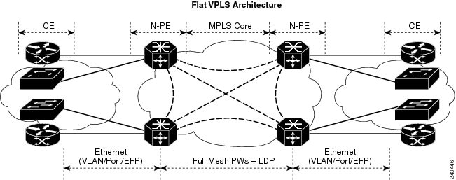
SUMMARY STEPS

  1. configure
  2. interface Bundle-ether10
  3. interface Bundle-ether10.999 l2transport
  4. encapsulation dot1q 999
  5. interface GigabitEthernet0/6/0/5
  6. bundle id 10 mode active
  7. interface GigabitEthernet0/6/0/6
  8. bundle id 10 mode active
  9. interface GigabitEthernet0/6/0/7.999 l2transport
  10. encapsulation dot1q 999
  11. interface TenGigE0/1/0/2.999 l2transport
  12. encapsulation dot1q 999
  13. l2vpn
  14. bridge group examples
  15. bridge-domain test-efp
  16. interface Bundle-ether10.999
  17. exit
  18. interface GigabitEthernet0/6/0/7.999
  19. exit
  20. interface TenGigE0/1/0/2.999
  21. Use the commit or end command.

DETAILED STEPS


Step 1

configure

Enters global configuration mode.

Step 2

interface Bundle-ether10

Creates a new bundle trunk interface.

Step 3

interface Bundle-ether10.999 l2transport

Creates an EFP under the new bundle trunk.

Step 4

encapsulation dot1q 999

Assigns VLAN ID of 999 to this EFP.

Step 5

interface GigabitEthernet0/6/0/5

Enters interface configuration mode. Changes configuration mode to act on GigabitEthernet0/6/0/5.

Step 6

bundle id 10 mode active

Establishes GigabitEthernet0/6/0/5 as a member of Bundle-ether10. The mode active keywords specify LACP protocol.

Step 7

interface GigabitEthernet0/6/0/6

Enters interface configuration mode. Changes configuration mode to act on GigabitEthernet0/6/0/6.

Step 8

bundle id 10 mode active

Establishes GigabitEthernet0/6/0/6 as a member of Bundle-ether10. The mode active keywords specify LACP protocol.

Step 9

interface GigabitEthernet0/6/0/7.999 l2transport

Creates an EFP under GigabitEthernet0/6/0/7.

Step 10

encapsulation dot1q 999

Assigns VLAN ID of 999 to this EFP.

Step 11

interface TenGigE0/1/0/2.999 l2transport

Creates an EFP under TenGigE0/1/0/2.

Step 12

encapsulation dot1q 999

Assigns VLAN ID of 999 to this EFP.

Step 13

l2vpn

Enters L2VPN configuration mode.

Step 14

bridge group examples

Creates the bridge group named examples.

Step 15

bridge-domain test-efp

Creates the bridge domain named test-efp, that is a member of bridge group examples.

Step 16

interface Bundle-ether10.999

Establishes Bundle-ether10.999 as an AC of the bridge domain named test-efp.

Step 17

exit

Exits bridge domain AC configuration submode, allowing next AC to be configured.

Step 18

interface GigabitEthernet0/6/0/7.999

Establishes GigabitEthernet0/6/0/7.999 as an AC of the bridge domain named test-efp.

Step 19

exit

Exits bridge domain AC configuration submode, allowing next AC to be configured.

Step 20

interface TenGigE0/1/0/2.999

Establishes interface TenGigE0/1/0/2.999 as an AC of bridge domain named test-efp.

Step 21

Use the commit or end command.

commit - Saves the configuration changes and remains within the configuration session.

end - Prompts user to take one of these actions:

  • Yes - Saves configuration changes and exits the configuration session.

  • No - Exits the configuration session without committing the configuration changes.

  • Cancel - Remains in the configuration mode, without committing the configuration changes.


Changing the Flood Optimization Mode

Perform this task to change the flood optimization mode under the bridge domain:

SUMMARY STEPS

  1. configure
  2. l2vpn
  3. bridge group bridge-group-name
  4. bridge-domain bridge-domain-name
  5. flood mode convergence-optimized
  6. Use the commit or end command.

DETAILED STEPS


Step 1

configure

Example:

RP/0/RSP0/CPU0:router# configure

Enters the Global Configuration mode.

Step 2

l2vpn

Example:

RP/0/RSP0/CPU0:router(config)# l2vpn

Enters L2VPN configuration mode.

Step 3

bridge group bridge-group-name

Example:


RP/0/RSP0/CPU0:router(config-l2vpn)# bridge group csco
RP/0/RSP0/CPU0:router(config-l2vpn-bg)#

Creates a bridge group so that it can contain bridge domains and then assigns network interfaces to the bridge domain.

Step 4

bridge-domain bridge-domain-name

Example:


RP/0/RSP0/CPU0:router(config-l2vpn-bg)# bridge-domain abc
RP/0/RSP0/CPU0:router(config-l2vpn-bg-bd)#

Establishes a bridge domain and enters l2vpn bridge group bridge domain configuration mode.

Step 5

flood mode convergence-optimized

Example:


RP/0/RSP0/CPU0:router(config-l2vpn-bg-bd)# flood mode convergence-optimized

Changes the default flood optimization mode from Bandwidth Optimization Mode to Convergence Mode.

Step 6

Use the commit or end command.

commit - Saves the configuration changes and remains within the configuration session.

end - Prompts user to take one of these actions:

  • Yes - Saves configuration changes and exits the configuration session.
  • No - Exits the configuration session without committing the configuration changes.
  • Cancel - Remains in the configuration mode, without committing the configuration changes.

Configuring VPLS with BGP Autodiscovery and Signaling: Example

This section contains these configuration examples for configuring the BGP autodiscovery and signaling feature:

LDP and BGP Configuration

The following figure illustrates an example of LDP and BGP configuration.

Figure 17. LDP and BGP Configuration


Configuration at PE1:

interface Loopback0
	ipv4 address 1.1.1.100 255.255.255.255
!
interface Loopback1
	ipv4 address 1.1.1.10 255.255.255.255
!
mpls ldp
	router-id 1.1.1.1
	interface GigabitEthernt0/1/0/0
!
router bgp 120
	address-family l2vpn vpls-vpws
!
	neighbor 2.2.2.20
	remote-as 120
	update-source Loopback1
	address-family l2vpn vpls-vpws
	signaling bgp disable
Configuration at PE2:

interface Loopback0
	ipv4 address 2.2.2.200 255.255.255.255
!
interface Loopback1
	ipv4 address 2.2.2.20 255.255.255.255
!
mpls ldp
	router-id 2.2.2.2
	interface GigabitEthernt0/1/0/0
!
router bgp 120
	address-family l2vpn vpls-vpws
!
	neighbor 1.1.1.10
	remote-as 120
	update-source Loopback1
	address-family l2vpn vpls-vpws

Minimum L2VPN Configuration for BGP Autodiscovery with BGP Signaling

This example illustrates the minimum L2VPN configuration required for BGP Autodiscovery with BGP Signaling, where any parameter that has a default value is not configured.

(config)# l2vpn
(config-l2vpn)# bridge group {bridge group name}
(config-l2vpn-bg)# bridge-domain {bridge domain name}
(config-l2vpn-bg-bd)# vfi {vfi name}
(config-l2vpn-bg-bd-vfi)# autodiscovery bgp
(config-l2vpn-bg-bd-vfi-ad)# vpn-id 10
(config-l2vpn-bg-bd-vfi-ad)# rd auto
(config-l2vpn-bg-bd-vfi-ad)# route-target 1.1.1.1:100
(config-l2vpn-bg-bd-vfi-ad-sig)# signaling-protocol bgp
(config-l2vpn-bg-bd-vfi-ad-sig)# ve-id 1
(config-l2vpn-bg-bd-vfi-ad-sig)# commit

VPLS with BGP Autodiscovery and BGP Signaling

The following figure illustrates an example of configuring VPLS with BGP autodiscovery (AD) and BGP Signaling.

Figure 18. VPLS with BGP autodiscovery and BGP signaling

VPLS with BGP autodiscovery and BGP signaling

Configuration at PE1:

l2vpn
  bridge group gr1
   bridge-domain bd1
    interface GigabitEthernet0/1/0/1.1
    vfi vf1
    ! AD independent VFI attributes
    vpn-id 100
    ! Auto-discovery attributes
    autodiscovery bgp
    rd auto
    route-target 2.2.2.2:100
    ! Signaling attributes
    signaling-protocol bgp
    ve-id 3
Configuration at PE2:

l2vpn
  bridge group gr1
   bridge-domain bd1
    interface GigabitEthernet0/1/0/2.1
    vfi vf1
    ! AD independent VFI attributes
    vpn-id 100
    ! Auto-discovery attributes
    autodiscovery bgp
    rd auto
    route-target 2.2.2.2:100
    ! Signaling attributes
    signaling-protocol bgp
    ve-id 5

This is an example of NLRI for VPLS with BGP AD and signaling:


Discovery Attributes
NLRI sent at PE1:

Length = 19
Router Distinguisher = 3.3.3.3:32770
VE ID = 3							
VE Block Offset = 1
VE Block Size = 10
Label Base = 16015
NLRI sent at PE2:

Length = 19
Router Distinguisher = 1.1.1.1:32775
VE ID = 5						
VE Block Offset = 1
VE Block Size = 10
Label Base = 16120

Minimum Configuration for BGP Autodiscovery with LDP Signaling

This example illustrates the minimum L2VPN configuration required for BGP Autodiscovery with LDP Signaling, where any parameter that has a default value is not configured.

(config)# l2vpn
(config-l2vpn)# bridge group {bridge group name}
(config-l2vpn-bg)# bridge-domain {bridge domain name}
(config-l2vpn-bg-bd)# vfi {vfi name}
(config-l2vpn-bg-bd-vfi)# autodiscovery bgp
(config-l2vpn-bg-bd-vfi-ad)# vpn-id 10
(config-l2vpn-bg-bd-vfi-ad)# rd auto
(config-l2vpn-bg-bd-vfi-ad)# route-target 1.1.1.1:100
(config-l2vpn-bg-bd-vfi-ad)# commit

VPLS with BGP Autodiscovery and LDP Signaling

The following figure illustrates an example of configuring VPLS with BGP autodiscovery (AD) and LDP Signaling.

Figure 19. VPLS with BGP autodiscovery and LDP signaling

VPLS with BGP autodiscovery and LDP signaling

Configuration at PE1:

l2vpn
  router-id 10.10.10.10
  bridge group bg1
   bridge-domain bd1
    vfi vf1
    vpn-id 100
    autodiscovery bgp
    rd 1:100
    router-target 12:12
Configuration at PE2:

l2vpn
  router-id 20.20.20.20
  bridge group bg1
   bridge-domain bd1
    vfi vf1
     vpn-id 100
     autodiscovery bgp
      rd 2:200
      router-target 12:12
      signaling-protocol ldp
       vpls-id 120:100
Discovery and Signaling Attributes
Configuration at PE1:

LDP Router ID - 1.1.1.1
BGP Router ID - 1.1.1.100
Peer Address - 1.1.1.10
L2VPN Router ID - 10.10.10.10	
Route Distinguisher - 1:100
Common Configuration between PE1 and PE2:

ASN - 120
VPN ID - 100
VPLS ID - 120:100
Route Target - 12:12
Configuration at PE2:

LDP Router ID - 2.2.2.2
BGP Router ID - 2.2.2.200
Peer Address - 2.2.2.20
L2VPN Router ID - 20.20.20.20	
Route Distinguisher - 2:200
Discovery Attributes
NLRI sent at PE1:

Source Address - 1.1.1.10
Destination Address - 2.2.2.20
Length - 14
Route Distinguisher - 1:100
L2VPN Router ID - 10.10.10.10
VPLS ID - 120:100
Route Target - 12:12
NLRI sent at PE2:

Source Address - 2.2.2.20
Destination Address - 1.1.1.10
Length - 14
Route Distinguisher - 2:200
L2VPN Router ID - 20.20.20.20
VPLS ID - 120:100
Route Target - 12:12
Enabling VC type 4 for BGP Autodiscovery

This example shows how to configure virtual connection type 4 in VPLS with BGP autodiscovery:


l2vpn
bridge group bg1
  bridge-domain bd1
   transport-mode vlan passthrough
   interface GigabitEthernet0/0/0/1.1
   !
   neighbor 2.2.2.2 pw-id 1
   !
   vfi vf1
    vpn-id 100
    autodiscovery bgp
     rd auto
     route-target 1:1
     signalining-protocol ldp
    !
   !
  !
!

VPLS with both BGP Autodiscovery and Manual Provisioning of VPLS Peers

This example shows VPLS configuration with BGP autodiscovery as well as manual provisioning of VPLS peers that are not participating in the BGP autodiscovery process.
!
l2vpn
 bridge group bg1
  bridge-domain bd1
   !
   vfi vfi1
    vpn-id 500
    autodiscovery bgp
     rd auto
     route-target 65533:12345678
     signaling-protocol ldp
      vpls-id 65533:12345678
    ! Manually provisioned peers
    neighbor 10.10.10.2 pw-id 102
!

Configuring Dynamic ARP Inspection: Example

This example shows how to configure basic dynamic ARP inspection under a bridge domain:

config
l2vpn
 bridge group MyGroup
 bridge-domain MyDomain
 dynamic-arp-inspection logging

This example shows how to configure basic dynamic ARP inspection under a bridge port:

config
l2vpn
 bridge group MyGroup
 bridge-domain MyDomain
  interface gigabitEthernet 0/1/0/0.1
 dynamic-arp-inspection logging

This example shows how to configure optional dynamic ARP inspection under a bridge domain:

l2vpn
  bridge group SECURE
    bridge-domain SECURE-DAI
      dynamic-arp-inspection
        logging
        address-validation
          src-mac
          dst-mac
           ipv4

This example shows how to configure optional dynamic ARP inspection under a bridge port:

l2vpn
  bridge group SECURE
    bridge-domain SECURE-DAI
      interface GigabitEthernet0/0/0/1.10
        dynamic-arp-inspection
          logging
          address-validation
           src-mac
           dst-mac
           ipv4

This example shows the output of the show l2vpn bridge-domain bd-name SECURE-DAI detail command:

#show l2vpn bridge-domain bd-name SECURE-DAI detail
Bridge group: SECURE, bridge-domain: SECURE-DAI, id: 2, state: up, 
…
Dynamic ARP Inspection: enabled, Logging: enabled
Dynamic ARP Inspection Address Validation:
   IPv4 verification: enabled    
   Source MAC verification: enabled
    Destination MAC verification: enabled
…
List of ACs:
 AC: GigabitEthernet0/0/0/1.10, state is up
…
    Dynamic ARP Inspection: enabled, Logging: enabled
    Dynamic ARP Inspection Address Validation:
        IPv4 verification: enabled
        Source MAC verification: enabled
        Destination MAC verification: enabled
        IP Source Guard: enabled, Logging: enabled

…
   Dynamic ARP inspection drop counters:
      packets: 1000, bytes: 64000

This example shows the output of the show l2vpn forwarding interface interface-name detail location location-name command:

#show l2vpn forwarding interface g0/0/0/1.10 det location 0/0/CPU0
Local interface: GigabitEthernet0/0/0/1.10, Xconnect id: 0x40001, Status: up

…
    Dynamic ARP Inspection: enabled, Logging: enabled
    Dynamic ARP Inspection Address Validation:
        IPv4 verification: enabled
        Source MAC verification: enabled
        Destination MAC verification: enabled
        IP Source Guard: enabled, Logging: enabled

This example shows the logging display:

LC/0/0/CPU0:Jun 16 13:28:28.697 : l2fib[188]: %L2-L2FIB-5-SECURITY_DAI_VIOLATION_AC : Dynamic ARP inspection in AC GigabitEthernet0_0_0_7.1000 detected violated packet - source MAC: 0000.0000.0065, destination MAC: 0000.0040.0000, sender MAC: 0000.0000.0064, target MAC: 0000.0000.0000, sender IP: 5.6.6.6, target IP: 130.10.3.2

LC/0/5/CPU0:Jun 16 13:28:38.716 : l2fib[188]: %L2-L2FIB-5-SECURITY_DAI_VIOLATION_AC : Dynamic ARP inspection in AC Bundle-Ether100.103 detected violated packet - source MAC: 0000.0000.0067, destination MAC: 0000.2300.0000, sender MAC: 0000.7800.0034, target MAC: 0000.0000.0000, sender IP: 130.2.5.1, target IP: 50.5.1.25

Configuring IP Source Guard: Example

This example shows how to configure basic IP source guard under a bridge domain:


config
l2vpn
 bridge group MyGroup
 bridge-domain MyDomain
 ip-source-guard logging

This example shows how to configure basic IP source guard under a bridge port:


config
l2vpn
 bridge group MyGroup
 bridge-domain MyDomain
  interface gigabitEthernet 0/1/0/0.1
 ip-source-guard 	logging

This example shows how to configure optional IP source guard under a bridge domain:


l2vpn
  bridge group SECURE
    bridge-domain SECURE-IPSG
       ip-source-guard
         logging

This example shows how to configure optional IP source guard under a bridge port:


l2vpn
  bridge group SECURE
    bridge-domain SECURE-IPSG
      interface GigabitEthernet0/0/0/1.10
        ip-source-guard
          logging

This example shows the output of the show l2vpn bridge-domain bd-name ipsg-name detail command:


# show l2vpn bridge-domain bd-name SECURE-IPSG detail
Bridge group: SECURE, bridge-domain: SECURE-IPSG, id: 2, state: up, 
…
  IP Source Guard: enabled, Logging: enabled
…
List of ACs:
 AC: GigabitEthernet0/0/0/1.10, state is up
…

   IP Source Guard: enabled, Logging: enabled
…
   IP source guard drop counters:
      packets: 1000, bytes: 64000

This example shows the output of the show l2vpn forwarding interface interface-name detail location location-name command:


# show l2vpn forwarding interface g0/0/0/1.10 detail location 0/0/CPU0
Local interface: GigabitEthernet0/0/0/1.10, Xconnect id: 0x40001, Status: up

…
    IP Source Guard: enabled, Logging: enabled

This example shows the logging display:


LC/0/0/CPU0:Jun 16 13:32:25.334 : l2fib[188]: %L2-L2FIB-5-SECURITY_IPSG_VIOLATION_AC : IP source guard in AC  GigabitEthernet0_0_0_7.1001 detected violated packet - source MAC: 0000.0000.0200, destination MAC: 0000.0003.0000, source IP: 130.0.0.1, destination IP: 125.34.2.5


LC/0/5/CPU0:Jun 16 13:33:25.530 : l2fib[188]: %L2-L2FIB-5-SECURITY_IPSG_VIOLATION_AC : IP source guard in AC Bundle-Ether100.100  detected violated packet - source MAC: 0000.0000.0064, destination MAC: 0000.0040.0000, source IP: 14.5.1.3, destination IP: 45.1.1.10

Configuring G.8032 Ethernet Ring Protection: Example

This sample configuration illustrates the elements that a complete G.8032 configuration includes:

# Configure the ERP profile characteristics if ERP instance behaviors are non-default.
ethernet ring g8032 profile ERP-profile
  timer wtr 60
  timer guard 100
  timer hold-off 1 
  non-revertive
  
# Configure CFM MEPs and configure to monitor the ring links.
ethernet cfm
  domain domain1 
    service link1 down-meps
	  continuity-check interval 100ms
      efd 
	  mep crosscheck
		mep-id 2
  domain domain2 
    service link2 down-meps
	  continuity-check interval 100ms
      efd protection-switching
	  mep crosscheck
		mep id 2

Interface Gig 0/0/0/0
  ethernet cfm mep domain domain1 service link1 mep-id 1
Interface Gig 1/1/0/0
  ethernet cfm mep domain domain2 service link2 mep-id 1 

# Configure the ERP instance under L2VPN
l2vpn
  ethernet ring g8032 RingA
    port0 interface g0/0/0/0
    port1 interface g0/1/0/0
    instance 1
      description BD2-ring
      profile ERP-profile
      rpl port0 owner
      vlan-ids 10-100
      aps channel 
        level 3
        port0 interface g0/0/0/0.1
        port1 interface g1/1/0/0.1 

# Set up the bridge domains
bridge group ABC
    bridge-domain BD2
      interface Gig 0/0/0/0.2
      interface Gig 0/1/0/0.2
      interface Gig 0/2/0/0.2

    bridge-domain BD2-APS
      interface Gig 0/0/0/0.1
      interface Gig 1/1/0/0.1

# EFPs configuration
interface Gig 0/0/0/0.1 l2transport
  encapsulation dot1q 5

interface Gig 1/1/0/0.1 l2transport
  encapsulation dot1q 5

interface g 0/0/0/0.2 l2transport
  encapsulation dot1q 10-100

interface g 0/1/0/0.2 l2transport
  encapsulation dot1q 10-100

interface g 0/2/0/0.2 l2transport
  encapsulation dot1q 10-100 

Configuring Interconnection Node: Example

This example shows you how to configure an interconnection node. The following figure illustrates an open ring scenario.

Figure 20. Open Ring Scenario - interconnection node

Open Ring Scenario - interconnection node

The minimum configuration required for configuring G.8032 at Router C (Open ring – Router C):

interface <ifname1.1> l2transport
	encapsulation dot1q X1
interface <ifname1.10> l2transport
	encapsulation dot1q Y1
interface <ifname2.10> l2transport
	encapsulation dot1q Y1
interface <ifname3.10> l2transport
	encapsulation dot1q Y1
l2vpn
ethernet ring g8032 <ring-name>
      port0 interface <main port ifname1>
      port1 interface none #? This router is connected to an interconnection node
      open-ring #? Mandatory when a router is part of an open-ring
      instance <1-2>
         inclusion-list vlan-ids  X1-Y1
         aps-channel
           Port0 interface <ifname1.1>
           Port1 none #? This router is connected to an interconnection node
	bridge group bg1
	   bridge-domain bd-aps#? APS-channel has its own bridge domain
	      <ifname1.1> #? There is only one APS-channel at the interconnection node
	   bridge-domain bd-traffic #? Data traffic has its own bridge domain
	      <ifname1.10>
	      <ifname2.10>
	      <ifname3.10>

Configuring the Node of an Open Ring: Example

This example shows you how to configure the node part of an open ring. The following figure illustrates an open ring scenario.

Figure 21. Open Ring Scenario

Open Ring Scenario

The minimum configuration required for configuring G.8032 at the node of the open ring (node part of the open ring at router F):

interface <ifname1.1> l2transport
	encapsulation dot1q X1
interface <ifname2.1> l2transport
	encapsulation dot1q X1
interface <ifname1.10> l2transport
	encapsulation dot1q Y1
interface <ifname2.10> l2transport
	encapsulation dot1q Y1
l2vpn
   ethernet ring g8032 <ring-name>
      port0 interface <main port ifname1>
      port1 interface <main port ifname2>
      open-ring #? Mandatory when a router is part of an open-ring
      instance <1-2>
         inclusion-list vlan-ids  X1-Y1
	     rpl port1 owner #? This node is RPL owner and <main port ifname2> is blocked
         aps-channel
           port0 interface <ifname1.1>
           port1 interface <ifname2.1>
	bridge group bg1
	   bridge-domain bd-aps#? APS-channel has its own bridge domain
	      <ifname1.1>
	      <ifname2.1>
	   bridge-domain bd-traffic #? Data traffic has its own bridge domain
	      <ifname1.10>
	      <ifname2.10>

Configuring Flow Aware Transport Pseudowire: Example

This sample configuration shows how to enable load balancing with FAT PW for VPWS.

l2vpn
pw-class class1
    encapsulation mpls
        load-balancing flow-label transmit
    !
 !
pw-class class2
    encapsulation mpls
        load-balancing flow-label both
    !

xconnect group group1
    p2p p1
        interface TenGigE 0/0/0/0.1
        neighbor 1.1.1.1 pw-id 1
            pw-class class1
        !
    !
! 

This sample configuration shows how to enable load balancing with FAT PW for VPLS.


Note

For VPLS, the configuration at the bridge-domain level is applied to all PWs (access and VFI PWs). Pseudowire classes are defined to override the configuration for manual PWs.
l2vpn
pw-class class1
 encapsulation mpls
 load-balancing flow-label both

bridge group group1
    bridge-domain domain1
        vfi vfi2-auto-bgp
                autodiscovery bgp
                   signaling-protocol bgp
                       load-balancing flow-label both static
               !
            !
        !
    !
    bridge-domain domain2
        vfi vfi2-auto-ldp
                autodiscovery bgp
                   signaling-protocol ldp
                       load-balancing flow-label both static
               !
            !
        !
    !
!

Configuring Pseudowire Headend: Example

This example shows how to configure pseudowire headend.

Consider the topology in the following figure.

Figure 22. Pseudowire Headend Example

There are multiple CEs connected to A-PE (each CE is connected by one link). There are two P routers between A-PE an S-PE in the access network. The S-PE is connected using two links to P1. These links L1 and L2 (on two different line cards on P1 and S-PE), e.g. Gig0/1/0/0 and Gig0/2/0/0 respectively.

The S-PE is connected by two links to P2, links L3 and L4 (on two different line cards on P2 and S-PE), e.g. Gig0/1/0/1 and Gig0/2/0/1 respectively. For each CE-APE link, a xconnect (AC-PW) is configured on the A-PE. A-PE uses router-id 100.100.100.100 for routing and PW signaling. Two router-ids on S-PE used for PW signaling, e.g. 111.111.111.111 and 112.112.112.112 (for rx pin-down), 110.110.110.110 is the router-id for routing.

CE Configuration

Consider two CEs that are connected through Ge0/3/0/0 (CE1 and A-PE) and Ge0/3/0/1 (CE2 and A-PE).

CE1


interface Gig0/3/0/0
 ipv4 address 10.1.1.1/24
router static 
 address-family ipv4 unicast
  110.110.110.110 Gig0/3/0/0
  A.B.C.D/N 110.110.110.110

CE2


interface Gig0/3/0/1
 ipv4 address 10.1.2.1/24
router static 
 address-family ipv4 unicast
  110.110.110.110 Gig0/3/0/1
  A.B.C.D/N 110.110.110.110

A-PE Configuration

At A-PE we have 1 xconnect for each CE connection. Here we give the configuration for the 2 CE connections above: both connections are L2 links which are in xconnects. Each xconnect has a PW destined to S-PE but we use a different neighbor address depending of where we want to pin-down the PW: [L1, L4] or [L2, L3]


interface Gig0/3/0/0
 l2transport
interface Gig0/3/0/1
 l2transport

l2vpn
 xconnect group pwhe
  p2p pwhe_spe_1
   interface Gig0/3/0/0
   neighbor 111.111.111.111 pw-id 1
  p2p pwhe_spe_2
   interface Gig0/3/0/1
   neighbor 112.112.112.112 pw-id 2

P Router Configuration

We need static routes on P routers for rx pindown on S-PE, i.e. to force PWs destined to a specific address to be transported over certain links.

P1


router static 
 address-family ipv4 unicast
  111.111.111.111 Gig0/1/0/0
  112.112.112.112 Gig0/2/0/0

P2


router static 
 address-family ipv4 unicast
  111.111.111.111 Gig0/2/0/1
  112.112.112.112 Gig0/1/0/1

S-PE Configuration

At S-PE we have 2 PW-HE interfaces (1 for each PW) and each uses a different interface list for tx pin-down (has to match the static config at P routers for rx pin-down). Each PW-HE has its PW going to A-PE (pw-id has to match what's at A-PE).


generic-interface-list il1
 interface gig0/1/0/0
 interface gig0/2/0/0
generic-interface-list il2
 interface gig0/1/0/1
 interface gig0/2/0/1

interface pw-ether1
 ipv4 address 10.1.1.2/24 
 attach generic-interface-list il1
interface pw-ether2
 ipv4 address 10.1.2.2/24
 attach generic-interface-list il2

l2vpn
 xconnect group pwhe
  p2p pwhe1
   interface pw-ether1
   neighbor 100.100.100.100 pw-id 1
  p2p pwhe2
   interface pw-ether2
   neighbor 100.100.100.100 pw-id 2

Configuring L2VPN over GRE: Example

Configure the PW core interfaces under IGP and ensure that the loopback is reachable. Configure the tunnel source such that the tunnel is the current loopback as well as destination of the peer PE loopback. Now, configure the GRE tunnel in IGP (OSPF or ISIS), and also under mpls ldp and ensure that the LDP neighbor is established between the PEs for the PW. This ensures that the PW is Up through the tunnel.

Configuration on PE1:

router ospf 1
router-id 1.1.1.1
 area 0
  interface Loopback0
  interface TenGigE0/0/0/1
router ospf 2
 router-id 200.200.200.200
 area 0
  interface Loopback1000
   interface tunnel-ip1
mpls ldp
 router-id 200.200.200.200
 interface tunnel-ip1

Configuration on PE2:

router ospf 1
 router-id 3.3.3.3
 area 0
  interface Loopback0
interface TenGigE0/2/0/3
router ospf 2
 router-id 201.201.201.201
 area 0
  interface Loopback1000
   interface tunnel-ip1
!
mpls ldp
 router-id 201.201.201.201
 interface tunnel-ip1

Configuring a GRE Tunnel as the Preferred Path for Pseudowire: Example

This example shows how to configure a GRE tunnel as the preferred path for a pseudowire.

l2vpn
 pw-class gre
  encapsulation mpls
  preferred-path interface tunnel-ip 1 fallback disable

Configuring a GRE Tunnel as Preferred Path for Pseudowire

Perform this task to configure a GRE tunnel as the preferred path for pseudowires.

SUMMARY STEPS

  1. configure
  2. l2vpn
  3. pw-class { name }
  4. encapsulation mpls
  5. preferred-path { interface } { tunnel-ip value | tunnel-te value | tunnel-tp value } [ fallback disable ]
  6. Use the commit or end command.

DETAILED STEPS


Step 1

configure

Example:

RP/0/RSP0/CPU0:router# configure

Enters the Global Configuration mode.

Step 2

l2vpn

Example:

RP/0/RSP0/CPU0:router(config)# l2vpn

Enters L2VPN configuration mode.

Step 3

pw-class { name }

Example:

RP/0/RSP0/CPU0:router(config-l2vpn)# pw-class gre

Configures the pseudowire class name.

Step 4

encapsulation mpls

Example:

RP/0/RSP0/CPU0:router(config-l2vpn-pwc)# encapsulation mpls

Configures the pseudowire encapsulation to MPLS.

Step 5

preferred-path { interface } { tunnel-ip value | tunnel-te value | tunnel-tp value } [ fallback disable ]

Example:

RP/0/RSP0/CPU0:router(config-l2vpn-pwc-encap-
mpls)# preferred-path interface tunnel-ip 1 fallback disable

Configures preferred path tunnel settings. If the fallback disable configuration is used and once the TE/TP tunnel is configured as the preferred path goes down, the corresponding pseudowire can also go down.

Note 
Ensure that fallback is supported.
Step 6

Use the commit or end command.

commit - Saves the configuration changes and remains within the configuration session.

end - Prompts user to take one of these actions:

  • Yes - Saves configuration changes and exits the configuration session.
  • No - Exits the configuration session without committing the configuration changes.
  • Cancel - Remains in the configuration mode, without committing the configuration changes.

Configuring VPLS LSM: Examples

This section provides examples on how to configure the VPLS LSM solution:

Enabling P2MP PW with RSVP-TE on a VFI: Example

This example shows how to enable P2MP PW with RSVP-TE on a VFI:

configure
l2vpn
 bridge group {bridge group name} 
  bridge-domain {bridge domain name}
   vfi {vfi name}
   multicast p2mp  
   transport rsvp-te
   attribute-set p2mp-te set1 
commit
!

Enabling BGP Autodiscover Signaling for P2MP PW on a VFI: Example

This example shows how to enable BGP Autodiscover Signaling for P2MP PW on a VFI:

configure 
l2vpn
 bridge group bg1 
   bridge-domain bd1
     vfi vfi1
     multicast p2mp  
     signaling protocol bgp 
 commit
!

Configuring VPN ID: Example

This example shows how to configure a VPN ID:

l2vpn
 
 bridge group bg1
  bridge-domain bd1
   interface GigabitEthernet0/1/0/0.1
   !
   interface GigabitEthernet0/1/0/0.2
   !
   vfi 1
    vpn-id 1001
    autodiscovery bgp
      rd auto
      route-target 1.1.1.1
      signaling protocol bgp
    !
   !

Configuring IGMP Snooping: Example

This example shows how to configure IGMP snooping:

igmp snooping profile profile1
 [no] default-bridge-domain all enable
!
l2vpn
  bridge group bg1
   bridge domain bd1
    [no] igmp snooping disable
    !
   !
  !
 !