Implementing Point to Point Layer 2 Services

This module provides conceptual and configuration information for point-to-point Layer 2 (L2) connectivity.

These point-to-point services are supported:

  • Local Switching—A point-to-point circuit internal to a single Cisco ASR 9000 Series Router, also known as local connect.

  • Pseudowires—A virtual point-to-point circuit from a Cisco ASR 9000 Series Router. Pseudowires are implemented over MPLS.


Note

Point to Point Layer 2 Services are also called as MPLS Layer 2 VPNs.


Note

For more information about Point to Point Layer 2 Services on the Cisco ASR 9000 Series Router and for descriptions of the commands listed in this module, see the “Related Documents” section.

Feature History for Implementing Point to Point Layer 2 Services

Release Modification

Release 3.7.2

This feature was introduced.

Release 3.9.0

Scale enhancements were introduced.

Release 4.0.0

Support was added for Any Transport over MPLS (AToM) features.

Release 4.0.1

Support was added for these features:

  • Pseudowire Load Balancing

  • Any Transport over MPLS (AToM) features:

    • HDLC over MPLS (HDLCoMPLS)

    • PPP over MPLS (PPPoMPLS)

Release 4.1.0

Support was added for the Flexible Router ID feature.

Release 4.2.0

Support was added for these features:

  • MPLS Transport Profile

  • Circuit EMulation (CEM) over Packet

Release 4.3.0

Support was added for the L2VPN Nonstop Routing feature.

Release 4.3.1

Support was added for these features:

  • L2TPv3 over IPv6 Tunnel

  • ATMoMPLS Cell Relay VP Mode

  • GTP Load Balancing

Release 5.1.0

Support was added for these features:

  • Two-way pseudowire (PW) for ATM/CEMoMPLS

  • PW grouping for Multi-Segment PW

  • Hot Standby PW for ATM/CEMoMPLS

  • MR-APS Integration with Hot-Standby PW

Release 5.1.2

Support was added for the following:

  • Dynamic Single Segment Pseudowire.

  • Faster network convergence after pseudowire failure.

Prerequisites for Implementing Point to Point Layer 2 Services

You must be in a user group associated with a task group that includes the proper task IDs. The command reference guides include the task IDs required for each command.

If you suspect user group assignment is preventing you from using a command, contact your AAA administrator for assistance.

Information About Implementing Point to Point Layer 2 Services

To implement Point to Point Layer 2 Services, you should understand these concepts:

Layer 2 Virtual Private Network Overview

Layer 2 Virtual Private Network (L2VPN) emulates the behavior of a LAN across an L2 switched, IP or MPLS-enabled IP network, allowing Ethernet devices to communicate with each other as they would when connected to a common LAN segment. Point-to-point L2 connections are vital when creating L2VPNs.

As Internet service providers (ISPs) look to replace their Frame Relay or Asynchronous Transfer Mode (ATM) infrastructures with an IP infrastructure, there is a need to provide standard methods of using an L2 switched, IP or MPLS-enabled IP infrastructure. These methods provide a serviceable L2 interface to customers; specifically, to provide virtual circuits between pairs of customer sites.

Building a L2VPN system requires coordination between the ISP and the customer. The ISP provides L2 connectivity; the customer builds a network using data link resources obtained from the ISP. In an L2VPN service, the ISP does not require information about a the customer's network topology, policies, routing information, point-to-point links, or network point-to-point links from other ISPs.

The ISP requires provider edge (PE) routers with these capabilities:

  • Encapsulation of L2 protocol data units (PDU) into Layer 3 (L3) packets.

  • Interconnection of any-to-any L2 transports.

  • Emulation of L2 quality-of-service (QoS) over a packet switch network.

  • Ease of configuration of the L2 service.

  • Support for different types of tunneling mechanisms (MPLS, L2TPv3, IPSec, GRE, and others).

  • L2VPN process databases include all information related to circuits and their connections.

Layer 2 Local Switching Overview

Local switching allows you to switch L2 data between two interfaces of the same type, (for example, Ethernet to Ethernet) and on the same router. The interfaces can be on the same line card, or on two different line cards. During these types of switching, Layer 2 address is used instead of the Layer 3 address. A local switching connection switches L2 traffic from one attachment circuit (AC) to the other. The two ports configured in a local switching connection are ACs with respect to that local connection. A local switching connection works like a bridge domain that has only two bridge ports; traffic enters one port of the local connection and leaves the other. However, because there is no bridging involved in a local connection, there is neither MAC learning nor flooding. Also, the ACs in a local connection are not in the UP state if the interface state is DOWN. (This behavior is also different when compared to that of a bridge domain.)

Local switching ACs utilize a full variety of L2 interfaces, including L2 trunk (main) interfaces, bundle interfaces, and EFPs.

Additionally, same-port local switching allows you to switch Layer 2 data between two circuits on the same interface.

ATMoMPLS with L2VPN Overview

ATMoMPLS is a type of Layer 2 point-to-point connection over an MPLS core.

To implement the ATMoMPLS feature, the Cisco ASR 9000 Series Router plays the role of provider edge (PE) router at the edge of a provider network in which customer edge (CE) devices are connected to the Cisco ASR 9000 Series Router.

Virtual Circuit Connection Verification on L2VPN

Virtual Circuit Connection Verification (VCCV) is an L2VPN Operations, Administration, and Maintenance (OAM) feature that allows network operators to run IP-based provider edge-to-provider edge (PE-to-PE) keepalive protocol across a specified pseudowire to ensure that the pseudowire data path forwarding does not contain any faults. The disposition PE receives VCCV packets on a control channel, which is associated with the specified pseudowire. The control channel type and connectivity verification type, which are used for VCCV, are negotiated when the pseudowire is established between the PEs for each direction.

Two types of packets can arrive at the disposition egress:

  • Type 1—Specifies normal Ethernet-over-MPLS (EoMPLS) data packets.

  • Type 2—Specifies VCCV packets.

Cisco ASR 9000 Series Router supports Label Switched Path (LSP) VCCV Type 1, which uses an inband control word if enabled during signaling. The VCCV echo reply is sent as IPv4 that is the reply mode in IPv4. The reply is forwarded as IP, MPLS, or a combination of both.

VCCV pings counters that are counted in MPLS forwarding on the egress side. However, on the ingress side, they are sourced by the route processor and do not count as MPLS forwarding counters.

Ethernet over MPLS

Ethernet-over-MPLS (EoMPLS) provides a tunneling mechanism for Ethernet traffic through an MPLS-enabled L3 core and encapsulates Ethernet protocol data units (PDUs) inside MPLS packets (using label stacking) to forward them across the MPLS network.

EoMPLS features are described in these subsections:

Ethernet Port Mode

In Ethernet port mode, both ends of a pseudowire are connected to Ethernet ports. In this mode, the port is tunneled over the pseudowire or, using local switching (also known as an attachment circuit-to-attachment circuit cross-connect) switches packets or frames from one attachment circuit (AC) to another AC attached to the same PE node.

The following figure provides an example of Ethernet port mode.

Figure 1. Ethernet Port Mode Packet Flow

Ethernet Port Mode Packet Flow

VLAN Mode

In VLAN mode, each VLAN on a customer-end to provider-end link can be configured as a separate L2VPN connection using virtual connection (VC) type 4 or VC type 5. VC type 5 is the default mode.

As illustrated in the following figure, the Ethernet PE associates an internal VLAN-tag to the Ethernet port for switching the traffic internally from the ingress port to the pseudowire; however, before moving traffic into the pseudowire, it removes the internal VLAN tag.

Figure 2. VLAN Mode Packet Flow

VLAN Mode Packet Flow

At the egress VLAN PE, the PE associates a VLAN tag to the frames coming off of the pseudowire and after switching the traffic internally, it sends out the traffic on an Ethernet trunk port.


Note

Because the port is in trunk mode, the VLAN PE doesn't remove the VLAN tag and forwards the frames through the port with the added tag.


Inter-AS Mode

Inter-AS is a peer-to-peer type model that allows extension of VPNs through multiple provider or multi-domain networks. This lets service providers peer up with one another to offer end-to-end VPN connectivity over extended geographical locations.

EoMPLS support can assume a single AS topology where the pseudowire connecting the PE routers at the two ends of the point-to-point EoMPLS cross-connects resides in the same autonomous system; or multiple AS topologies in which PE routers can reside on two different ASs using iBGP and eBGP peering.

The following figure illustrates MPLS over Inter-AS with a basic double AS topology with iBGP/LDP in each AS.

Figure 3. EoMPLS over Inter-AS: Basic Double AS Topology

QinQ Mode

QinQ is an extension of 802.1Q for specifying multiple 802.1Q tags (IEEE 802.1QinQ VLAN Tag stacking). Layer 3 VPN service termination and L2VPN service transport are enabled over QinQ sub-interfaces.

The Cisco ASR 9000 Series Routers implement the Layer 2 tunneling or Layer 3 forwarding depending on the subinterface configuration at provider edge routers. This function only supports up to two QinQ tags on the SPA and fixed PLIM:

  • Layer 2 QinQ VLANs in L2VPN attachment circuit: QinQ L2VPN attachment circuits are configured under the Layer 2 transport subinterfaces for point-to-point EoMPLS based cross-connects using both virtual circuit type 4 and type 5 pseudowires and point-to-point local-switching-based cross-connects including full interworking support of QinQ with 802.1q VLANs and port mode.

  • Layer 3 QinQ VLANs: Used as a Layer 3 termination point, both VLANs are removed at the ingress provider edge and added back at the remote provider edge as the frame is forwarded.

Layer 3 services over QinQ include:

  • IPv4 unicast and multicast

  • IPv6 unicast and multicast

  • MPLS

  • Connectionless Network Service (CLNS) for use by Intermediate System-to-Intermediate System (IS-IS) Protocol

In QinQ mode, each CE VLAN is carried into an SP VLAN. QinQ mode should use VC type 5, but VC type 4 is also supported. On each Ethernet PE, you must configure both the inner (CE VLAN) and outer (SP VLAN).

The following figure illustrates QinQ using VC type 4.

Figure 4. EoMPLS over QinQ Mode


QinAny Mode

In the QinAny mode, the service provider VLAN tag is configured on both the ingress and the egress nodes of the provider edge VLAN. QinAny mode is similar to QinQ mode using a Type 5 VC, except that the customer edge VLAN tag is carried in the packet over the pseudowire, as the customer edge VLAN tag is unknown.

Quality of Service

Using L2VPN technology, you can assign a quality of service (QoS) level to both Port and VLAN modes of operation.

L2VPN technology requires that QoS functionality on PE routers be strictly L2-payload-based on the edge-facing interfaces (also know as attachment circuits). The following figure illustrates L2 and L3 QoS service policies in a typical L2VPN network.

Figure 5. L2VPN QoS Feature Application

L2VPN QoS Feature Application

The following figure shows four packet processing paths within a provider edge device where a QoS service policy can be attached. In an L2VPN network, packets are received and transmitted on the edge-facing interfaces as L2 packets and transported on the core-facing interfaces as MPLS (EoMPLS).

Figure 6. L2VPN QoS Reference Model

L2VPN QoS Reference Model

High Availability

L2VPN uses control planes in both route processors and line cards, as well as forwarding plane elements in the line cards.

The availability of L2VPN meets these requirements:

  • A control plane failure in either the route processor or the line card will not affect the circuit forwarding path.

  • The router processor control plane supports failover without affecting the line card control and forwarding planes.

  • L2VPN integrates with existing Label Distribution Protocol (LDP) graceful restart mechanism.

Preferred Tunnel Path

Preferred tunnel path functionality lets you map pseudowires to specific traffic-engineering tunnels. Attachment circuits are cross-connected to specific MPLS traffic engineering tunnel interfaces instead of remote PE router IP addresses (reachable using IGP or LDP). Using preferred tunnel path, it is always assumed that the traffic engineering tunnel that transports the L2 traffic runs between the two PE routers (that is, its head starts at the imposition PE router and its tail terminates on the disposition PE router).


Note

  • Currently, preferred tunnel path configuration applies only to MPLS encapsulation.


Multisegment Pseudowire

Pseudowires transport Layer 2 protocol data units (PDUs) across a public switched network (PSN). A multisegment pseudowire is a static or dynamically configured set of two or more contiguous pseudowire segments. These segments act as a single pseudowire, allowing you to:

  • Manage the end-to-end service by separating administrative or provisioning domains.

  • Keep IP addresses of provider edge (PE) nodes private across interautonomous system (inter-AS) boundaries. Use IP address of autonomous system boundary routers (ASBRs) and treat them as pseudowire aggregation routers. The ASBRs join the pseudowires of the two domains.

A multisegment pseudowire can span either an inter-AS boundary or two multiprotocol label switching (MPLS) networks.

Figure 7. Multisegment Pseudowire: Example


A pseudowire is a tunnel between two PE nodes. There are two types of PE nodes:

  • A Switching PE (S-PE) node

    • Terminates PSN tunnels of the preceding and succeeding pseudowire segments in a multisegment pseudowire.

    • Switches control and data planes of the preceding and succeeding pseudowire segments of the multisegment pseudowire.

  • A Terminating PE (T-PE) node

    • Located at both the first and last segments of a multisegment pseudowire.

    • Where customer-facing attachment circuits (ACs) are bound to a pseudowire forwarder.


Note

Every end of a multisegment pseudowire must terminate at a T-PE.


A multisegment pseudowire is used in two general cases when:

  • It is not possible to establish a PW control channel between the source and destination PE nodes.

    For the PW control channel to be established, the remote PE node must be accessible. Sometimes, the local PE node may not be able to access the remote node due to topology, operational, or security constraints.

    A multisegment pseudowire dynamically builds two discrete pseudowire segments and performs a pseudowire switching to establish a PW control channel between the source and destination PE nodes.

  • Pseudowire Edge To Edge Emulation (PWE3) signaling and encapsulation protocols are different.

    The PE nodes are connected to networks employing different PW signaling and encapsulation protocols. Sometimes, it is not possible to use a single segment PW.

    A multisegment pseudowire, with the appropriate interworking performed at the PW switching points, enables PW connectivity between the PE nodes in the network.

Pseudowire Redundancy

Pseudowire redundancy allows you to configure your network to detect a failure in the network and reroute the Layer 2 service to another endpoint that can continue to provide service. This feature provides the ability to recover from a failure of either the remote provider edge (PE) router or the link between the PE and customer edge (CE) routers.

L2VPNs can provide pseudowire resiliency through their routing protocols. When connectivity between end-to-end PE routers fails, an alternative path to the directed LDP session and the user data takes over. However, there are some parts of the network in which this rerouting mechanism does not protect against interruptions in service.

Pseudowire redundancy enables you to set up backup pseudowires. You can configure the network with redundant pseudowires and redundant network elements.

Prior to the failure of the primary pseudowire, the ability to switch traffic to the backup pseudowire is used to handle a planned pseudowire outage, such as router maintenance.


Note

Pseudowire redundancy is provided only for point-to-point Virtual Private Wire Service (VPWS) pseudowires.

Pseudowire Load Balancing

To maximize networks while maintaining redundancy typically requires traffic load balancing over multiple links. To achieve better and more uniformed distribution, load balancing on the traffic flows that are part of the provisioned pipes is desirable. Load balancing can be flow based according to the IP addresses, Mac addresses, or a combination of those. Load balancing can be flow based according to source or destination IP addresses, or source or destination MAC addresses. Traffic falls back to default flow based MAC addresses if the IP header cannot proceed or IPv6 is be flow based.

This feature applies to pseudowires under L2VPN; this includes VPWS and VPLS.


Note

Enabling virtual circuit (VC) label based load balancing for a pseudowire class overrides global flow based load balancing under L2VPN.

L2 Traffic Tunneling with IP Load Balance Hashing for MPLS Encapsulated Packets

If the frame is IP-based, the load-balancing flow “src-dst-ip” configuration causes the Layer 2 interfaces to use the IP header for flow balancing hash calculation. If the frame is not IP-based, the MAC header is used for the hash calculation. In previous releases, for an MPLS header between the MAC and IP headers, the code would use the MAC header for the flow balancing hash.

From Release 6.4.1 onwards, the code analyzes the MPLS header, and if an IP header is available, it uses that for hash calculation.

If the MPLS label stack is more than four labels deep, the code stops looking for an IP header and reverts to the MAC header hash calculation.

When L2VPN flow-based src-dst-ip load-balancing is configured, and if a payload with encapsulated GTP is used, the GTP ID is considered for load-balancing criteria. Starting from Release 6.5.1, you do not have to configure the cef load-balancing command to use GTP ID as a criteria for load-balancing for L2VPN scenarios. However, you must explicitly configure CEF load-balancing for Layer 3 scenarios.

Pseudowire Grouping

When pseudowires (PWs) are established, each PW is assigned a group ID that is common for all PWs created on the same physical port. When a physical port becomes non-functional or disabled, Automatic Protection Switching (APS) signals the peer router to get activated and L2VPN sends a single message to advertise the status change of all PWs that have the Group ID associated with the physical port. A single L2VPN signal thus avoids a lot of processing and loss in reactivity.

For CEM interfaces, various levels of configuration are permitted for the parent controllers, such as T1 and T3, framed or unframed. To achieve best grouping, the physical controller handle is used as the group ID.


Note

Pseudowire grouping is disabled by default.


Network convergence for pseudowires can take longer than the usual two seconds in events such as:
  • Manual reload of an active working router

  • Interface or controller shutdown

  • Reload or shutdown or power disable of a line card on an enabled protect router

  • Router Processor fail-over (RPFO) on an enabled protect router

  • Simultaneous failure of two controllers or Shared Port Adapters (SPAs)

  • Two Automatic Protection Switching (APS) group switchovers

Ethernet Wire Service

An Ethernet Wire Service is a service that emulates a point-to-point Ethernet segment. This is similar to Ethernet private line (EPL), a Layer 1 point-to-point service, except the provider edge operates at Layer 2 and typically runs over a Layer 2 network. The EWS encapsulates all frames that are received on a particular UNI and transports these frames to a single-egress UNI without reference to the contents contained within the frame. The operation of this service means that an EWS can be used with VLAN-tagged frames. The VLAN tags are transparent to the EWS (bridge protocol data units [BPDUs])—with some exceptions. These exceptions include IEEE 802.1x, IEEE 802.2ad, and IEEE 802.3x, because these frames have local significance and it benefits both the customer and the Service Provider to terminate them locally.

Since the service provider simply accepts frames on an interface and transmits these without reference to the actual frame (other than verifying that the format and length are legal for the particular interface) the EWS is indifferent to VLAN tags that may be present within the customer Ethernet frames.

EWS subscribes to the concept of all-to-one bundling. That is, an EWS maps a port on one end to a point-to-point circuit and to a port on another end. EWS is a port-to-port service. Therefore, if a customer needs to connect a switch or router to n switches or routers it will need n ports and n pseudowires or logical circuits.

One important point to consider is that, although the EWS broadly emulates an Ethernet Layer 1 connection, the service is provided across a shared infrastructure, and therefore it is unlikely that the full interface bandwidth will be, or needs to be, available at all times. EWS will typically be a sub-line rate service, where many users share a circuit somewhere in their transmission path. As a result, the cost will most likely be less than that of EPL. Unlike a Layer 1 EPL, the SP will need to implement QoS and traffic engineering to meet the specific objectives of a particular contract. However, if the customer's application requires a true wire rate transparent service, then an EPL service—delivered using optical transmission devices such as DWDM (dense wavelength division multiplexing), CDWM (coarse wavelength division multiplexing), or SONET/SDH—should be considered.

IGMP Snooping

IGMP snooping provides a way to constrain multicast traffic at Layer 2. By snooping the IGMP membership reports sent by hosts in the bridge domain, the IGMP snooping application can set up Layer 2 multicast forwarding tables to deliver traffic only to ports with at least one interested member, significantly reducing the volume of multicast traffic.

Configured at Layer 3, IGMP provides a means for hosts in an IPv4 multicast network to indicate which multicast traffic they are interested in and for routers to control and limit the flow of multicast traffic in the network (at Layer 3).

IGMP snooping uses the information in IGMP membership report messages to build corresponding information in the forwarding tables to restrict IP multicast traffic at Layer 2. The forwarding table entries are in the form <Route, OIF List>, where:

  • Route is a <*, G> route or <S, G> route.

  • OIF List comprises all bridge ports that have sent IGMP membership reports for the specified route plus all Multicast Router (mrouter) ports in the bridge domain.

The IGMP snooping feature can provide these benefits to a multicast network:

  • Basic IGMP snooping reduces bandwidth consumption by reducing multicast traffic that would otherwise flood an entire VPLS bridge domain.

  • With optional configuration options, IGMP snooping can provide security between bridge domains by filtering the IGMP reports received from hosts on one bridge port and preventing leakage towards the hosts on other bridge ports.

  • With optional configuration options, IGMP snooping can reduce the traffic impact on upstream IP multicast routers by suppressing IGMP membership reports (IGMPv2) or by acting as an IGMP proxy reporter (IGMPv3) to the upstream IP multicast router.

Refer to the Implementing Layer 2 Multicast with IGMP Snooping module in the Cisco ASR 9000 Series Aggregation Services Router Multicast Configuration Guide for information on configuring IGMP snooping.

The applicable IGMP snooping commands are described in the Cisco ASR 9000 Series Aggregation Services Router Multicast Command Reference.

IP Interworking

Customer deployments require a solution to support AToM with disparate transport at network ends. This solution must have the capability to translate transport on one customer edge (CE) device to another transport, for example, Frame relay to Ethernet. The Cisco ASR 9000 Series SPA Interface Processor-700 and the Cisco ASR 9000 Series Ethernet line cards enable the Cisco ASR 9000 Series Routers to support multiple legacy services.

IP Interworking is a solution for transporting Layer 2 traffic over an IP/MPLS backbone. It accommodates many types of Layer 2 frames such as Ethernet and Frame Relay using AToM tunnels. It encapsulates packets at the provider edge (PE) router, transports them over the backbone to the PE router on the other side of the cloud, removes the encapsulation, and transports them to the destination. The transport layer can be Ethernet on one end and Frame relay on the other end. IP interworking occurs between disparate endpoints of the AToM tunnels.


Note

Only routed interworking is supported between Ethernet and Frame Relay based networks for MPLS and Local-connect scenarios.

The following figure shows the interoperability between an Ethernet attachment VC and a Frame Relay attachment VC.

Figure 8. IP Interworking over MPLS Core


An attachment circuit (AC) is a physical or logical port or circuit that connects a CE device to a PE device. A pseudowire (PW) is a bidirectional virtual connection (VC) connecting two ACs. In an MPLS network, PWs are carried inside an LSP tunnel. The core facing line card on the PE1 and PE2 could be a Cisco ASR 9000 Series SPA Interface Processor-700 or a Cisco ASR 9000 Series Ethernet line card.

In the IP Interworking mode, the Layer 2 (L2) header is removed from the packets received on an ingress PE, and only the IP payload is transmitted to the egress PE. On the egress PE, an L2 header is appended before the packet is transmitted out of the egress port.

In Figure above , CE1 and CE2 could be a Frame Relay (FR) interface or a GigabitEthernet (GigE) interface. Assuming CE1 is a FR and CE2 is either a GigE or dot1q, or QinQ. For packets arriving from an Ethernet CE (CE2), ingress LC on the PE (PE2) facing the CE removes L2 framing and forwards the packet to egress PE (PE1) using IPoMPLS encapsulation over a pseudowire. The core facing line card on egress PE removes the MPLS labels but preserves the control word and transmits it to the egress line card facing FR CE (CE1). At the FR PE, after label disposition, the Layer 3 (L3) packets are encapsulated over FR.

Similarly, IP packets arriving from the FR CE are translated into IPoMPLS encapsulation over the pseudowire. At the Ethernet PE side, after label disposition, the PE adds L2 Ethernet packet header back to the packet before transmitting it to the CE, as the packets coming out from the core carry only the IP payload.

These modes support IP Interworking on AToM:

  • Ethernet to Frame Relay

    Packets arriving from the Ethernet CE device have MAC (port-mode, untagged, single, double tag), IPv4 header and data. The Ethernet line card removes the L2 framing and then forwards the L3 packet to the egress line card. The egress line card adds the FR L2 header before transmitting it from the egress port.

  • Ethernet to Ethernet

    Both the CE devices are Ethernet. Each ethernet interface can be port-mode, untagged, single, or double tag, although this is not a typical scenario for IP interworking.

AToM iMSG

This feature enables an interworking layer in the access network(s) to terminate all non-Ethernet functionality and translate these connections to a Ethernet centric service which can be terminated on the Layer 3 edge routers. Currently, the time-division multiplexing (TDM) based services terminate on the Layer 3 edge routers directly. A simplified and more cost optimized model for the L3 networks is enabled by moving the TDM complexity into the access layer.

The Layer 2 encapsulation is removed from an IP packet by the ingress PE’s attachment circuit facing ingress line card. The MPLS encapsulated IP packet payload is then sent across the fabric to the core facing egress line card. The egress line card then transmits the packet through the MPLS core. On the remote PE, the MPLS label is removed, Layer 2 header of the egress AC is added and finally the packet is sent to the connected CE. L2VPN VPWS has been enhanced to support:

  • Point-to-Point Protocol (PPP)

  • High-level Data Link Control (HDLC)

  • Multilink Point-to-Point Protocol (MLPPP)

  • QOS support for all the encapsulation types

    For more information on QoS, see the Cisco ASR 9000 Series Aggregation Services Router Modular Quality of Service Configuration.

The TDM ACs can be configured on these SPAs:

  • SPA-8XCHT1/E1

  • SPA-4XCT3/DS0

  • SPA-1XCHSTM1/OC3

  • SPA-2XCHOC12/DS0

  • SPA-1XCHOC48/DS3

  • SPA-4XT3/E3

  • SPA-4XOC3-POS-V2

  • SPA-8XOC3-POS

  • SPA-8XOC12-POS

  • SPA-1XOC48POS/RPR

  • SPA-2XOC48POS/RPR

Any Transport over MPLS

Any Transport over MPLS (AToM) transports Layer 2 packets over a Multiprotocol Label Switching (MPLS) backbone. This enables service providers to connect customer sites with existing Layer 2 networks by using a single, integrated, packet-based network infrastructure. Using this feature, service providers can deliver Layer 2 connections over an MPLS backbone, instead of using separate networks.

AToM encapsulates Layer 2 frames at the ingress PE router, and sends them to a corresponding PE router at the other end of a pseudowire, which is a connection between the two PE routers. The egress PE removes the encapsulation and sends out the Layer 2 frame.

The successful transmission of the Layer 2 frames between PE routers is due to the configuration of the PE routers. You set up a connection, called a pseudowire, between the routers. You specify this information on each PE router:

  • The type of Layer 2 data that will be transported across the pseudowire, such as Ethernet and Frame Relay

  • The IP address of the loopback interface of the peer PE router, which enables the PE routers to communicate.

  • A unique combination of peer PE IP address and VC ID that identifies the pseudowire.

Control Word Processing

The control word contains forward explicit congestion notification (FECN), backward explicit congestion notification (BECN) and DE bits in case of frame relay connection.

Control word is mandatory for:

  • Frame Relay

  • ATM AAL5

  • Frame Relay to Ethernet bridged interworking

  • cHDLC/PPP IP interworking

  • CEM (Circuit Emulation)

The system does not map bits from one transport end point to another across an AToM IP Interworking connection.

Whenever supported, control word is also recommended for pseudowires, as it enables proper load balancing without packet desequencing independent of L2VPN packet content. Without control word the heuristics used to perform load balancing cannot achieve optimal results in all cases.

High-level Data Link Control over MPLS

The attachment circuit (AC) is a main interface configured with HDLC encapsulation. Packets to or from the AC are transported using an AToM pseudowire (PW) of VC type 0x6 to or from the other provider edge (PE) router over the MPLS core network.

With HDLC over MPLS, the entire HDLC packet is transported. The ingress PE router removes only the HDLC flags and FCS bits.

PPP over MPLS

The attachment circuit (AC) is a main interface configured with PPP encapsulation. Packets to or from the AC are transported through an AToM PW of VC type 0x7 to or from the other provider edge (PE) routers over the MPLS core network.

With PPP over MPLS, the ingress PE router removes the flags, address, control field, and the FCS bits.

Frame Relay over MPLS

Frame Relay over MPLS (FRoMPLS) provides leased line type of connectivity between two Frame Relay islands. Frame Relay traffic is transported over the MPLS network.


Note

The Data Link Connection Identifier (DLCI) DCLI-DLCI mode is supported. A control word (required for DLCI-DLCI mode) is used to carry additional control information.

When a Provider Edge (PE) router receives a Frame Relay protocol packet from a subscriber site, it removes the Frame Relay header and Frame Check Sequence (FCS) and appends the appropriate Virtual Circuit (VC) label. The removed Backward Explicit Congestion Notification (BECN), Forward Explicit Congestion Notification (FECN), Discard Eligible (DE) and Command/Response (C/R) bits are (for DLCI-DLCI mode) sent separately using a control word.

MPLS Transport Profile

MPLS transport profile (MPLS-TP) tunnels provide the transport network service layer over which IP and MPLS traffic traverse. Within the MPLS-TP environment, pseudowires (PWs) use MPLS-TP tunnels as the transport mechanism. MPLS-TP tunnels help transition from SONET/SDH TDM technologies to packet switching, to support services with high bandwidth utilization and low cost. Transport networks are connection oriented, statically provisioned, and have long-lived connections. Transport networks usually avoid control protocols that change identifiers (like labels). MPLS-TP tunnels provide this functionality through statically provisioned bidirectional label switched paths (LSPs).

For more information on configuring MPLS transport profile, refer to the Cisco ASR 9000 Series Aggregation Services Router MPLS Configuration Guide.

MPLS-TP supports these combinations of static and dynamic multisegment pseudowires:

  • Static-static

  • Static-dynamic

  • Dynamic-static

  • Dynamic-dynamic

MPLS-TP supports one-to-one L2VPN pseudowire redundancy for these combinations of static and dynamic pseudowires:

  • Static pseudowire with a static backup pseudowire

  • Static pseudowire with a dynamic backup pseudowire

  • Dynamic pseudowire with a static backup pseudowire

  • Dynamic pseudowire with a dynamic backup pseudowire

The existing TE preferred path feature is used to pin down a PW to an MPLS-TP transport tunnel. See Configuring Preferred Tunnel Path for more information on configuring preferred tunnel path. For a dynamic pseudowire, PW status is exchanged through LDP whereas for static PW, status is transported in PW OAM message. See Configuring PW Status OAM for more information on configuring PW status OAM. By default, alarms are not generated when the state of a PW changes due to change in the state of MPLS TP tunnel carrying that PW.

Circuit Emulation Over Packet Switched Network

Circuit Emulation over Packet (CEoP) is a method of carrying TDM circuits over packet switched network. CEoP is similar to a physical connection. The goal of CEoP is to replace leased lines and legacy TDM networks.

CEoP operates in two major modes:

  • Unstructured mode is called SAToP (Structure Agnostic TDM over Packet)

    SAToP addresses only structure-agnostic transport, i.e., unframed E1, T1, E3 and T3. It segments all TDM services as bit streams and then encapsulates them for transmission over a PW tunnel. This protocol can transparently transmit TDM traffic data and synchronous timing information. SAToP completely disregards any structure and provider edge routers (PEs) do not need to interpret the TDM data or to participate in the TDM signaling. The protocol is a simple way for transparent transmission of PDH bit-streams.

  • Structured mode is named CESoPSN (Circuit Emulation Service over Packet Switched Network)

    Compared with SAToP, CESoPSN transmits emulated structured TDM signals. That is, it can identify and process the frame structure and transmit signaling in TDM frames. It may not transmit idle timeslot channels, but only extracts useful timeslots of CE devices from the E1 traffic stream and then encapsulates them into PW packets for transmission.CEoP SPAs are half-height (HH) Shared Port Adapters (SPA) and the CEoP SPA family consists of 24xT1/E1, 2xT3/E3, and 1xOC3/STM1 unstructured and structured (NxDS0) quarter rate, half height SPAs.

Figure 9. Enterprise Data Convergence using Circuit Emulation over Packet

The CEM functionality is supported only on Engine 5 line cards having CEoP SPAs. CEM is supported on:

  • 1-port Channelized OC3 STM1 ATM CEoP SPA (SPA-1CHOC3-CE-ATM)

    CESoPSN and SAToP can use MPLS, UDP/IP, and L2TPv3 as the underlying transport mechanism. This release supports only MPLS transport mechanism.

CEoP SPA supports these modes of operation:

  • Circuit Emulation Mode (CEM)

  • ATM Mode

  • IMA Mode


Note

Only CEM mode is supported.


Benefits of Circuit Emulation over Packet Switched Network

CEM offers these benefits to the service provider and end-users:

  • Saving cost in installing equipment.

  • Saving cost in network operations; as leased lines are expensive, limiting their usage to access only mode saves significant costs.

  • Ensuring low maintenance cost because only the core network needs to be maintained.

  • Utilizing the core network resources more efficiently with packet switched network, while keeping investment in access network intact.

  • Providing cheaper services to the end-user.

L2VPN Nonstop Routing

The L2VPN Nonstop Routing (NSR) feature avoids label distribution path (LDP) sessions from flapping on events such as process failures (crash) and route processor failover (RP FO). NSR on process failure (crash) is supported by performing RP FO, if you have enabled NSR using NSR process failure switchover.

NSR enables the router (where failure has occurred) to maintain the control plane states without a graceful restart (GR). NSR, by definition, does not require any protocol extension and typically uses Stateful Switch Over (SSO) to maintain it’s control plane states.


Note

NSR is enabled by default for L2VPN on Cisco IOS XR 64 bit operating system. You cannot configure the nsr command under L2VPN configuration submode.


L2TPv3 over IPv6

A L2TPv3 over IPv6 tunnel is a static L2VPN cross-connect that uses Layer 2 Tunneling Protocol version 3 (L2TPv3) over IPv6, with a unique IPv6 source address for each cross-connect. The L2TPv3 over IPv6 tunnels consists of one L2TPv3 tunnel for each subscriber VLAN. The unique IPv6 address completely identifies the customer, and the service that is delivered.


Note

L2TPv3 over IPv6 tunnels are supported on the ASR 9000 Enhanced Ethernet line cards by a scale of 15000 crossconnects for each router and line card.

Note

nV satellite access interfaces do not support L2TPv3 over IPv6.

Overview

L2TPv3 defines the L2TP protocol for tunneling Layer 2 payloads over an IP core network using Layer 2 virtual private networks (VPNs). Traffic between two customer network sites is encapsulated in IP packets carrying L2TP data messages (payload) and sent across an IP network. The backbone routers of the IP network treat this payload in the same manner as it treats any other IP traffic. Implementing L2TPv3 over IPv6 provides an opportunity to utilize unique source IPv6 addresses to directly identify Ethernet attachment circuits. In this case, processing of the L2TPv3 session ID is bypassed; this is because each tunnel has only one associated session. This local optimization, however, does not hinder the ability to continue supporting circuit multiplexing through the session ID for other L2TPv3 tunnels on the same router.

For more information on:

Traffic Injection from L2TPv3 over IPv6 Tunnel

Traffic Injection from L2TPv3 over IPv6 Tunnel feature allows you to inject diagnostic traffic through Layer 2 Tunneling Protocol version 3 (L2TPv3) Switched Port Analyzer (SPAN) tunnel. The diagnostic traffic allows you to monitor and troubleshoot the network traffic. You can send the diagnostic traffic from customer office (CO) using traffic generator towards the customer or towards the network.

In previous releases, with traffic mirroring feature the user was only able to send the mirrored traffic from customer towards the monitoring device, the mirror tunnel was unidirectional.

Traffic mirroring copies traffic from one or more source ports and sends the copied traffic to one or more destinations for analysis by a network analyzer or other monitoring device. Traffic mirroring does not affect the flow of traffic on the source interfaces or sub-interfaces, and allows the mirrored traffic to be sent to a destination interface or sub-interface

Restrictions

  • This feature is not supported on bundle and sub-bundle interfaces, supported only on main and sub interfaces.

  • Diagnostic traffic directed from network to customer does not traverse the same path as the actual non-diagnostic network to customer traffic. As a result, any issue with the core facing interface is not diagnosed.

  • Diagnostic traffic will mix with the actual customer traffic. It is the responsibility of CO to ensure that it does not cause any problems to the customer, and CO is able to differentiate diagnostic traffic from customer traffic in the SPAN tunnel.

  • Physical port features are not available in the inward inject path, so the problems in the physical port features, such as, EOAM or BIA MAC are not diagnosed.

  • Bundle and other hash calculations, such as, ECMP, are not available, so the only customer interface supported is a physical interface.

  • For Layer 3, only IPv4 and IPv6 diagnostic payload is supported.

Topology

Figure 10. Traffic Injection from L2TPv3 over IPv6 Tunnel


Consider a topology where an L2TPv3 tunnel is created between two ASR 9000 devices. Customer Office (CO) sends diagnostic traffic using traffic generator over L2TPv3 over IPv6 tunnel to the ASR 9000 router. The ASR 9000 router on the left-hand side sends the diagnostic traffic towards the customer as though it is sent from the network or sends the diagnostic traffic towards the network as though it is sent from the customer.

The diagnostic traffic header contains destination MAC address, source MAC address, and IP payload. If the header contains destination MAC address of the ASR 9000 router, the diagnostic traffic is sent to the network as though it sent from the customer. If the header contains source MAC address of the ASR 9000 router, the diagnostic traffic is sent to the customer as though it sent from the network.

Configure Traffic Injection from L2TPv3 over IPv6 Tunnel

Perform these tasks on ASR 9000 router, which is on the left-hand side to configure Traffic Injection from L2TPv3 over IPv6 Tunnel feature,
  • Create a pseudowire monitor session with inject interface

  • Attach the monitor session to an interface which needs to be spanned

  • Configure L2VPN xconnect with monitor session


/* Create a pseudowire monitor session with inject interface */

Router# configure
Router(config)# monitor-session span1
Router(config-mon)# destination pseudowire
Router(config-mon)# inject-interface tenGigE 0/1/0/0/0
Router(config-mon)# commit
Router(config-mon)# end

/* Attach the monitor session to an interface which needs to be spanned */

Router# configure
Router(config)# int tenGigE 0/1/0/0/0
Router(config-subif)# monitor-session span1 ethernet
Router(config-if-mon)# commit

/* Configure L2VPN  xconnect with monitor session */

Router(config)# l2vpn
Router(config-l2vpn)# xconnect group xc-span1
Router(config-l2vpn-xc)# p2p span-session1
Router(config-l2vpn-xc-p2p)# monitor-session span1
Router(config-l2vpn-xc-p2p)# neighbor ipv6 1112::1:1 pw-id 101
Router(config-l2vpn-xc-p2p-pw)# pw-class ts
Router(config-l2vpn-xc-p2p-pw)# source 1111::1:1
Router(config-l2vpn-xc-p2p-pw)# l2tp static local cookie size 8 value 0x1 0xa1 local session 101
Router(config-l2vpn-xc-p2p-pw)# l2tp static remote cookie size 8 value 0xa1 0x1 remote session 101
Router(config-l2vpn-xc-p2p-pw)# commit
Router(config-l2vpn-xc-p2p-pw)# end
Running Configuration

configure
 monitor-session span1
  destination pseudowire
  inject-interface tenGigE 0/1/0/0/0
  !
!

configure
 int tenGigE 0/1/0/0/0
  monitor-session span1 ethernet
  !
!

l2vpn
 xconnect group xc-span1
  p2p span-session1
   monitor-session span1
   neighbor ipv6 1112::1:1 pw-id 101
    pw-class ts
    source 1111::1:1
    l2tp static
     local cookie size 8 value 0x1 0xa1
     local session 101
     remote cookie size 8 value 0xa1 0x1
     remote session 101
    !
   !
  !
Verification

Verify that the source MAC address and destination MAC address are matching.


/* Verify that the source MAC address is matching */

Router#show monitor-session span1 counters 
Monitor-session span1
  TenGigE0/1/0/0/0.1
    Rx replicated: 248 packets, 247086 octets
    Tx replicated: 20001 packets, 20000094 octets
    Non-replicated: 0 packets, 0 octets


Router#show interface tenGigE 0/1/0/7/8 accounting 
TenGigE0/1/0/7/8.1
  Protocol              Pkts In         Chars In     Pkts Out        Chars Out
  IPV6_UNICAST            10001         10480072        10005         10480632
  IPV6_MULTICAST              1              104            0                0
  IPV6_ND                     2              212            1               72


Router#show interface tenGigE 0/1/0/0/0 accounting 
TenGigE0/1/0/0/0.1
  Protocol              Pkts In         Chars In     Pkts Out        Chars Out
  IPV6_UNICAST                2              136        10002          9780144
  IPV6_ND

/* Verify that the destination MAC address is matching */

Router#show monitor-session counters 
Monitor-session span1
  TenGigE0/1/0/0/0.1
    Rx replicated: 10001 packets, 10000094 octets
    Tx replicated: 1 packets, 94 octets
    Non-replicated: 0 packets, 0 octets


Router#show interface tenGigE 0/1/0/7/8 accounting 
TenGigE0/1/0/7/8.1
  Protocol              Pkts In         Chars In     Pkts Out        Chars Out
  IPV6_UNICAST            10000         10480000        10000         10480000
  IPV6_MULTICAST              0                0            1              104
  IPV6_ND                     0                0            1              104


Router#show interface tenGigE 0/1/0/0/0 accounting 
TenGigE0/1/0/0/0.1
  Protocol              Pkts In         Chars In     Pkts Out        Chars Out
  IPV6_UNICAST            10000          9780000            0                0
  IPV6_ND                     1               82            1               72

L2TPv3 over IPv4

Layer 2 Tunneling Protocol version 3 (L2TPv3) over IPv4 provides a dynamic mechanism for tunneling Layer 2 (L2) circuits across a packet-oriented data network, with multiple attachment circuits multiplexed over a single pair of IP address endpoints, using the L2TPv3 session ID as a circuit discriminator.

The following figure shows how the L2TPv3 feature is used to set up VPNs using Layer 2 tunneling over an IP network. All traffic between two customer network sites is encapsulated in IP packets carrying L2TP data messages and sent across an IP network. The backbone routers of the IP network treat the traffic as any other IP traffic and needn’t know anything about the customer networks.

Figure 11. L2TPv3 Operation

L2TPv3 Operation

In the above figure the PE routers R1 and R2 provide L2TPv3 services. The R1 and R2 routers communicate with each other using a pseudowire over the IP backbone network through a path comprising the interfaces int1 and int2 , the IP network, and interfaces int3 and int4 . The CE routers R3 and R4 communicate through a pair of cross-connected Ethernet or 802.1q VLAN interfaces using an L2TPv3 session. The L2TPv3 session tu1 is a pseudowire configured between interface int1 on R1 and interface int4 on R2. Any packet arriving on interface int1 on R1 is encapsulated and sent through the pseudowire control-channel (tu1) to R2. R2 decapsulates the packet and sends it on interface int4 to R4. When R4 needs to send a packet to R3, the packet follows the same path in reverse.


Note

L2TPv3 over IPv4 feature is supported only on Cisco ASR 9000 High Density 100GE Ethernet line cards.


Note

nV satellite access interfaces do not support L2TPv3 over IPv4.


For more information on:

Dynamic Single-Segment Pseudowire

A single-segment pseudowire (SS-PW) is a point-to-point pseudowire (PW) where the PW segment is present between two PE routers.

In this feature, a single-segment pseudowire is established between two PE routers of the same autonomous system (AS) dynamically using the FEC 129 information. The objective of this feature is to ensure interoperability of the Cisco routers with the third-party routers.

Active and Passive Signaling

The T-PE on which the SS-PW is initiated and the signaling message is transmitted from is called as the source-terminating PE (ST-PE). The T-PE that waits and responds to the SS-PW signaling message is called the target-terminating PE (TT-PE).

The signaling flow from the ST-PE to TT-PE is referred to as the forward direction signaling or the active signaling. The signaling flow from the TT-PE to ST-PE is referred to as the reverse direction signaling or the passive signaling.

Generally, the PE with the highest prefix address takes the active role and becomes the ST-PE, and the other PE becomes the passive TT-PE.

The following figure illustrates the SS-PW signaling flow between ST-PE and TT-PE:

Figure 12. Single-Segment Pseudowire Between ST-PE and TT-PE


Functionality of Dynamic Single Segment Pseudowire

The dynamic discovery of the pseudowire path from the ST-PE to the T-PE is achieved using the L2 route table. The route table entries, that is, a list of prefix and associated next-hops to the L2VPN are populated by BGP.


Note

In Release 5.1.2, Cisco supports only the routable prefix to reach the TAII on the T-PE. The routable prefix is the neighbor address of the targeted-LDP session. The reachability of packets from the source to the destination is achieved by user configurations (see Configuring L2VPN Single Segment Pseudowire) However, BGP supports MS-PW Subsequent Address Family Identifiers (SAFI) that is used to exchange the L2 routes across all the PEs. SS-PW uses the BGP MS-PW address family to function. To ensure interoperability with other third-party routers, Cisco advertises a single BGP MS-PW route per T-PE where the value of AC-ID (attachment circuit-identifier) is a wild-card entry.


The supported pseudowire features are pw-status, pw-grouping, and tag-impose vlan.

The following figure illustrates the E-line Services Network with SS-PWs:

Figure 13. E-Line Services Network with SS-PWs

Prerequisites for Configuring L2VPN Single Segment Pseudowires

MPLS LDP, IGP, BGP, L2VPN, and interfaces must be configured on the two end points of the PW:
  • Configuring MPLS Label Distribution Protocol.

  • Configuring Interior Gateway Protocol (IGP).

  • Configure Border Gateway Protocol (BGP).

  • Configuring an Interface or Connection for L2VPN.

Restrictions for Configuring L2VPN Single Segment Pseudowires

  • The routed pseudowire can only be enabled on Virtual Private Wire Service (VPWS) cross connects.

  • A cross-connect cannot have both ends configured as “neighbor routed” pseudowire.

  • SS-PW is not supported as the other member of the cross-connect, that is, at a T-PE, one end of the cross-connect can be the termination of the SS-PW and the other end can either be an attachment circuit (AC) or a PW-HE.

  • Source AII and AC-ID (attachment circuit identifier) are unique per router.

  • L2TP and MPLS static are not supported.

Configuring L2VPN Single Segment Pseudowire

To configure single segment pseudowire in the network, do the following:

  1. (Optional) Configuring the related L2VPN Global Parameters. See Configuring L2VPN Global Parameters

    This procedure is used to overwrite the default BGP Route Distinguisher (RD) auto-generated value and also the Autonomous System Number (ASN) and Route Identifier (RID) of BGP.

  2. Configuring L2VPN VPWS SS-PW

  3. Configuring L2VPN MS-PW Address Family Under BGP

    The address family is configured under BGP to exchange the dynamic pseudowire routes.

Configuring L2VPN Global Parameters

Perform this task to configure L2VPN global parameters.

SUMMARY STEPS

  1. configure
  2. l2vpn
  3. router-id router-id
  4. pw-routing
  5. global-id global-id
  6. bgp
  7. rd route-distinguisher
  8. Use the commit or end command.

DETAILED STEPS


Step 1

configure

Example:

RP/0/RSP0/CPU0:router# configure

Enters the Global Configuration mode.

Step 2

l2vpn

Example:

RP/0/RSP0/CPU0:router(config)# l2vpn

Enters Layer 2 VPN configuration mode.

Step 3

router-id router-id

Example:

RP/0/RSP0/CPU0:router(config)# router 2.2.2.2 

Specifies the router ID.

Step 4

pw-routing

Example:

RP/0/RSP0/CPU0:router(config-l2vpn)# pw-routing 

Enables pseudowire routing capabilities and enters the pseudowire routing configuration submode

Step 5

global-id global-id

Example:

RP/0/RSP0/CPU0:router(config-l2vpn-pwr)# global-id 1000 

Configures the L2VPN global ID value for the router.

Step 6

bgp

Example:

RP/0/RSP0/CPU0:router(config-l2vpn-pwr)# bgp 

Enables the BGP pseudowire routing capabilities and enters the BGP configuration submode.

Step 7

rd route-distinguisher

Example:

RP/0/RSP0/CPU0:router(config-l2vpn-pwr-bgp)# rd 192.168.1.3:10

Configures the BGP route distinguisher.

Step 8

Use the commit or end command.

commit - Saves the configuration changes and remains within the configuration session.

end - Prompts user to take one of these actions:

  • Yes - Saves configuration changes and exits the configuration session.
  • No - Exits the configuration session without committing the configuration changes.
  • Cancel - Remains in the configuration mode, without committing the configuration changes.

Configuring L2VPN VPWS SS-PW

Perform this task to configure L2VPN VPWS SS-PWs.

SUMMARY STEPS

  1. configure
  2. interface typeinterface-path-id
  3. l2vpn
  4. xconnect group group-name
  5. p2p xconnect-name
  6. interface type interface-path-id
  7. neighbor routed global-id: prefix: ac-id source ac-id
  8. (optional) pw-class class-name
  9. Use the commit or end command.

DETAILED STEPS


Step 1

configure

Example:

RP/0/RSP0/CPU0:router# configure

Enters the Global Configuration mode.

Step 2

interface typeinterface-path-id

Example:

RP/0/RSP0/CPU0:routerRP/0/RP00RSP0/CPU0:router# interface TenGigE0/1/0/12 

Enters interface configuration mode and configures an interface.

Step 3

l2vpn

Example:

RP/0/RSP0/CPU0:router(config)# l2vpn 

Enters Layer 2 VPN configuration mode.

Step 4

xconnect group group-name

Example:

RP/0/RSP0/CPU0:router(config-l2vpn)# xconnect group pw-he1

Configures a cross-connect group name using a free-format 32-character string.

Step 5

p2p xconnect-name

Example:

RP/0/RSP0/CPU0:router(config-l2vpn-xc)# p2p pw-ss

Enters P2P configuration submode.

Step 6

interface type interface-path-id

Example:

RP/0/RSP0/CPU0:router(config-l2vpn-xc-p2p)# interface gigabitethernet 0/1/0/9

Specifies the interface type and instance.

Step 7

neighbor routed global-id: prefix: ac-id source ac-id

Example:

RP/0/RSP0/CPU0:router(config-l2vpn-xc-p2p)# neighbor routed 100:2.2.2.2:10 source 10

Enables pseudowire routing configuration submode for the p2p cross-connect.

Step 8

(optional) pw-class class-name

Example:

RP/0/RSP0/CPU0:router(config-l2vpn-xc-p2p-pwr)# pw-class dynamic_sspw

Enters pseudowire class submode, allowing you to define a pseudowire class template.

Step 9

Use the commit or end command.

commit - Saves the configuration changes and remains within the configuration session.

end - Prompts user to take one of these actions:

  • Yes - Saves configuration changes and exits the configuration session.
  • No - Exits the configuration session without committing the configuration changes.
  • Cancel - Remains in the configuration mode, without committing the configuration changes.

Configuring L2VPN MS-PW Address Family Under BGP

Perform this task to configure L2VPN MS-PW address family under BGP:

SUMMARY STEPS

  1. configure
  2. router bgp autonomous-system-number
  3. address-family l2vpn mspw
  4. neighbor ip-address
  5. address-family l2vpn mspw
  6. Use the commit or end command.

DETAILED STEPS


Step 1

configure

Example:
RP/0/RSP0/CPU0:router# configure

Enters the Global Configuration mode.

Step 2

router bgp autonomous-system-number

Example:

RP/0/RSP0/CPU0:router(config)# router bgp 100

Enters router configuration mode for the specified routing process.

Step 3

address-family l2vpn mspw

Example:

RP/0/RSP0/CPU0:router(config-bgp)# address-family l2vpn mspw

Specifies the L2VPN address family and enters address family configuration mode.

Step 4

neighbor ip-address

Example:

RP/0/RSP0/CPU0:router(config-bgp)# neighbor 10.10.10.1 

Adds the IP address of the neighbor in the specified autonomous system.

Step 5

address-family l2vpn mspw

Example:

RP/0/RSP0/CPU0:router(config-bgp-nbr-af)# address-family l2vpn mspw 

Specifies the L2VPN address family of the neighbor and enters address family configuration mode.

Step 6

Use the commit or end command.

commit - Saves the configuration changes and remains within the configuration session.

end - Prompts user to take one of these actions:

  • Yes - Saves configuration changes and exits the configuration session.
  • No - Exits the configuration session without committing the configuration changes.
  • Cancel - Remains in the configuration mode, without committing the configuration changes.

EVPN Virtual Private Wire Service (VPWS)

The EVPN-VPWS is a BGP control plane solution for point-to-point services. It implements the signaling and encapsulation techniques for establishing an EVPN instance between a pair of PEs. It has the ability to forward traffic from one network to another without MAC lookup. The use of EVPN for VPWS eliminates the need for signaling single-segment and multi-segment PWs for point-to-point Ethernet services. You can also configure the PWHE interface and a bridge domain access pseudowire using EVPN-VPWS.

EVPN-VPWS single homed technology works on IP and MPLS core; IP core to support BGP and MPLS core for switching packets between the endpoints.

Information About EVPN-VPWS Single Homed

The EVPN-VPWS single homed solution requires per EVI Ethernet Auto Discovery route. EVPN defines a new BGP Network Layer Reachability Information (NLRI) used to carry all EVPN routes. BGP Capabilities Advertisement used to ensure that two speakers support EVPN NLRI (AFI 25, SAFI 70) as per RFC 4760.

The architecture for EVPN VPWS is that the PEs run Multi-Protocol BGP in control-plane. The following image describes the EVPN-VPWS configuration:

  • The VPWS service on PE1 requires the following three elements to be specified at configuration time:
    • The VPN ID (EVI)

    • The local AC identifier (AC1) that identifies the local end of the emulated service.

    • The remote AC identifier (AC2) that identifies the remote end of the emulated service.

    PE1 allocates a MPLS label per local AC for reachability.

  • The VPWS service on PE2 is set in the same manner as PE1. The three same elements are required and the service configuration must be symmetric.

    PE2 allocates a MPLS label per local AC for reachability.

  • PE1 advertise a single EVPN per EVI Ethernet AD route for each local endpoint (AC) to remote PEs with the associated MPLS label.

    PE2 performs the same task.

  • On reception of EVPN per EVI EAD route from PE2, PE1 adds the entry to its local L2 RIB. PE1 knows the path list to reach AC2, for example, next hop is PE2 IP address and MPLS label for AC2.

    PE2 performs the same task.

Benefits of EVPN-VPWS
The following are the benefits of EVPN-VPWS:
  • Scalability is achieved without signaling pseudowires.

  • Ease of provisioning

  • Pseudowires (PWs) are not used.

  • Leverages BGP best path selection (optimal forwarding).

Prerequisites for EVPN-VPWS

  • Ensure BGP is configured for EVPN SAFI.

  • BGP session between PEs with 'address-family l2vpn evpn' to exchange EVPN routes.

Restrictions for EVPN-VPWS

  • The VPN ID is unique per router.

  • When specifying a list of route targets, they must be unique per PE (per BGP address-family).

How to Implement Point to Point Layer 2 Services

This section describes the tasks required to implement Point to Point Layer 2 Services:

Configuring an Interface or Connection for Point to Point Layer 2 Services

Perform this task to configure an interface or a connection for Point to Point Layer 2 Services.

SUMMARY STEPS

  1. configure
  2. interface type interface-path-id
  3. l2transport
  4. exit
  5. interface type interface-path-id
  6. Use the commit or end command.
  7. show interface type interface-id

DETAILED STEPS


Step 1

configure

Example:


RP/0/RSP0/CPU0:router# configure

Enters the Global Configuration mode.

Step 2

interface type interface-path-id

Example:


RP/0/RSP0/CPU0:router(config)# interface TenGigE 0/0/0/0

Enters interface configuration mode and configures an interface.

Step 3

l2transport

Example:


RP/0/RSP0/CPU0:router(config-if)# l2transport

Enables L2 transport on the selected interface.

Step 4

exit

Example:


RP/0/RSP0/CPU0:router(config-if-l2)# exit

Exits the current configuration mode.

Step 5

interface type interface-path-id

Example:


RP/0/RSP0/CPU0:router(config)# interface TenGigE 0/0/0/0

Enters interface configuration mode and configures an interface.

Step 6

Use the commit or end command.

commit - Saves the configuration changes and remains within the configuration session.

end - Prompts user to take one of these actions:

  • Yes - Saves configuration changes and exits the configuration session.
  • No - Exits the configuration session without committing the configuration changes.
  • Cancel - Remains in the configuration mode, without committing the configuration changes.
Step 7

show interface type interface-id

Example:

RP/0/RSP0/CPU0:router show interface TenGigE 0/0/0/0

(Optional) Displays the configuration settings you committed for the interface.


Configuring Local Switching

Perform this task to configure local switching.

SUMMARY STEPS

  1. configure
  2. l2vpn
  3. xconnect group group-name
  4. p2p xconnect-name
  5. interface type interface-path-id
  6. interface type interface-path-id
  7. Use the commit or end command.

DETAILED STEPS


Step 1

configure

Example:

RP/0/RSP0/CPU0:router# configure

Enters the Global Configuration mode.

Step 2

l2vpn

Example:


RP/0/RSP0/CPU0:router(config-subif)# l2vpn

Enters L2VPN configuration mode.

Step 3

xconnect group group-name

Example:


RP/0/RSP0/CPU0:router(config-l2vpn)# xconnect group grp_1

Enters the name of the cross-connect group.

Step 4

p2p xconnect-name

Example:


RP/0/RSP0/CPU0:router(config-l2vpn-xc)# p2p vlan1

Enters a name for the point-to-point cross-connect.

Step 5

interface type interface-path-id

Example:


RP/0/RSP0/CPU0:router(config-l2vpn-xc-p2p)# interface TenGigE 0/7/0/6.5

Specifies the interface type ID. The choices are:

  • GigabitEthernet: Gigabit Ethernet/IEEE 802.3 interfaces

  • TenGigE: TenGigabit Ethernet/IEEE 802.3 interfaces

  • CEM: Circuit Emulation interface

Step 6

interface type interface-path-id

Example:


RP/0/RSP0/CPU0:router(config-l2vpn-xc-p2p)# interface GigabitEthernet0/4/0/30

Specifies the interface type ID. The choices are:

  • GigabitEthernet: Gigabit Ethernet/IEEE 802.3 interfaces

  • TenGigE: TenGigabit Ethernet/IEEE 802.3 interfaces

Step 7

Use the commit or end command.

commit - Saves the configuration changes and remains within the configuration session.

end - Prompts user to take one of these actions:

  • Yes - Saves configuration changes and exits the configuration session.
  • No - Exits the configuration session without committing the configuration changes.
  • Cancel - Remains in the configuration mode, without committing the configuration changes.

Configuring Local Connection Redundancy

Perform this task to configure local connection redundancy.

SUMMARY STEPS

  1. configure
  2. l2vpn
  3. xconnect group group-name
  4. p2p xconnect-name
  5. backup interface type interface-path-id
  6. interface type interface-path-id
  7. interface type interface-path-id
  8. Use the commit or end command.

DETAILED STEPS


Step 1

configure

Example:

RP/0/RSP0/CPU0:router# configure

Enters the Global Configuration mode.

Step 2

l2vpn

Example:

RP/0/RSP0/CPU0:router(config-subif)# l2vpn

Enters L2VPN configuration mode.

Step 3

xconnect group group-name

Example:

RP/0/RSP0/CPU0:router(config-l2vpn)# xconnect group grp_1

Enters the name of the cross-connect group.

Step 4

p2p xconnect-name

Example:


RP/0/RSP0/CPU0:router(config-l2vpn-xc)# p2p vlan1

Enters a name for the point-to-point cross-connect.

Step 5

backup interface type interface-path-id

Example:


RP/0/RSP0/CPU0:router(config-l2vpn-xc-p2p)# backup interface Bundle-Ether 0/7/0/6.5

Configures local connect redundancy.

Note 

The attachment circuit (AC) must be bundle interface that is part of MC-LAG. The backup interfaces can either be bundle or Ethernet port.

Step 6

interface type interface-path-id

Example:


RP/0/RSP0/CPU0:router(config-l2vpn-xc-p2p)# interface Bundle-Ether 0/7/0/6.2

Specifies the interface type ID. The choices are:

  • GigabitEthernet: Gigabit Ethernet/IEEE 802.3 interfaces

  • TenGigE: TenGigabit Ethernet/IEEE 802.3 interfaces

  • CEM: Circuit Emulation interface

Step 7

interface type interface-path-id

Example:


RP/0/RSP0/CPU0:router(config-l2vpn-xc-p2p)# interface Bundle-Ether 0/7/0/6.1

Specifies the interface type ID. The choices are:

  • GigabitEthernet: Gigabit Ethernet/IEEE 802.3 interfaces

  • TenGigE: TenGigabit Ethernet/IEEE 802.3 interfaces

Step 8

Use the commit or end command.

commit - Saves the configuration changes and remains within the configuration session.

end - Prompts user to take one of these actions:

  • Yes - Saves configuration changes and exits the configuration session.
  • No - Exits the configuration session without committing the configuration changes.
  • Cancel - Remains in the configuration mode, without committing the configuration changes.

Configuring Static Point-to-Point Cross-Connects


Note

Consider this information about cross-connects when you configure static point-to-point cross-connects:
  • An cross-connect is uniquely identified with the pair; the cross-connect name must be unique within a group.

  • A segment (an attachment circuit or pseudowire) is unique and can belong only to a single cross-connect.

  • A static VC local label is globally unique and can be used in one pseudowire only.

  • No more than 16,000 cross-connects can be configured per router.


Note

Static pseudowire connections do not use LDP for signaling.


Perform this task to configure static point-to-point cross-connects.

SUMMARY STEPS

  1. configure
  2. l2vpn
  3. xconnect group group-name
  4. p2p xconnect-name
  5. interface type interface-path-id
  6. neighbor A.B.C.D pw-id pseudowire-id
  7. mpls static label local { value } remote { value }
  8. Use the commit or end command.

DETAILED STEPS


Step 1

configure

Example:


RP/0/RSP0/CPU0:router# configure

Enters the Global Configuration mode.

Step 2

l2vpn

Example:


RP/0/RSP0/CPU0:router(config)# l2vpn

Enters L2VPN configuration mode.

Step 3

xconnect group group-name

Example:


RP/0/RSP0/CPU0:router(config-l2vpn)# xconnect group grp_1


Enters the name of the cross-connect group.

Step 4

p2p xconnect-name

Example:


RP/0/RSP0/CPU0:router(config-l2vpn-xc)# p2p vlan1

Enters a name for the point-to-point cross-connect.

Step 5

interface type interface-path-id

Example:


RP/0/RSP0/CPU0:router(config-l2vpn-xc-p2p)# interface gigabitethernet 0/1/0/9

Specifies the interface type and instance.

Step 6

neighbor A.B.C.D pw-id pseudowire-id

Example:


RP/0/RSP0/CPU0:router(config-l2vpn-xc-p2p)# neighbor 10.2.2.2 pw-id 2000

Configures the pseudowire segment for the cross-connect.

Use the A.B.C.D argument to specify the IP address of the cross-connect peer.

Note 

A.B.C.D can be a recursive or non-recursive prefix.

Optionally, you can disable the control word or set the transport-type to Ethernet or VLAN.

Step 7

mpls static label local { value } remote { value }

Example:


RP/0/RSP0/CPU0:router(config-l2vpn-xc-p2p-pw)# mpls static label local 699 remote 890

Configures local and remote label ID values.

Step 8

Use the commit or end command.

commit - Saves the configuration changes and remains within the configuration session.

end - Prompts user to take one of these actions:

  • Yes - Saves configuration changes and exits the configuration session.
  • No - Exits the configuration session without committing the configuration changes.
  • Cancel - Remains in the configuration mode, without committing the configuration changes.

Configuring Dynamic Point-to-Point Cross-Connects

Perform this task to configure dynamic point-to-point cross-connects.


Note

For dynamic cross-connects, LDP must be up and running.


SUMMARY STEPS

  1. configure
  2. l2vpn
  3. xconnect group group-name
  4. p2p xconnect-name
  5. interface type interface-path-id
  6. neighbor A.B.C.D pw-id pseudowire-id
  7. Use the commit or end command.

DETAILED STEPS


Step 1

configure

Example:


RP/0/RSP0/CPU0:router# configure

Enters the Global Configuration mode.

Step 2

l2vpn

Example:


RP/0/RSP0/CPU0:router(config)# l2vpn

Enters L2VPN configuration mode.

Step 3

xconnect group group-name

Example:


RP/0/RSP0/CPU0:router(config-l2vpn)# xconnect group grp_1

Enters the name of the cross-connect group.

Step 4

p2p xconnect-name

Example:


RP/0/RSP0/CPU0:router(config-l2vpn-xc)# p2p vlan1

Enters a name for the point-to-point cross-connect.

Step 5

interface type interface-path-id

Example:


RP/0/RSP0/CPU0:router(config-l2vpn-xc-p2p)# interface GigabitEthernet0/0/0/0.1

Specifies the interface type ID. The choices are:

  • GigabitEthernet: GigabitEthernet/IEEE 802.3 interfaces.

  • TenGigE: TenGigabitEthernet/IEEE 802.3 interfaces.

  • CEM: Circuit Emulation interface

Step 6

neighbor A.B.C.D pw-id pseudowire-id

Example:

RP/0/RSP0/CPU0:router(config-l2vpn-xc-p2p)# neighbor 2.2.2.2 pw-id 2000

Configures the pseudowire segment for the cross-connect.

Optionally, you can disable the control word or set the transport-type to Ethernet or VLAN.

Step 7

Use the commit or end command.

commit - Saves the configuration changes and remains within the configuration session.

end - Prompts user to take one of these actions:

  • Yes - Saves configuration changes and exits the configuration session.
  • No - Exits the configuration session without committing the configuration changes.
  • Cancel - Remains in the configuration mode, without committing the configuration changes.

Configuring Inter-AS

The Inter-AS configuration procedure is identical to the L2VPN cross-connect configuration tasks (see “Configuring Static Point-to-Point Cross-Connects” section and “Configuring Dynamic Point-to-Point Cross-Connects” section) except that the remote PE IP address used by the cross-connect configuration is now reachable through iBGP peering.


Note

You must be knowledgeable about IBGP, EBGP, and ASBR terminology and configurations to complete this configuration.


Configuring L2VPN Quality of Service

This section describes how to configure L2VPN quality of service (QoS) in port mode and mode, VLAN mode, Frame Relay and ATM sub-interfaces.

Restrictions

The l2transport command cannot be used with any IP address, L3, or CDP configuration.

Configuring an L2VPN Quality of Service Policy in Port Mode

This procedure describes how to configure an L2VPN QoS policy in port mode.


Note

In port mode, the interface name format does not include a subinterface number; for example, GigabitEthernet0/1/0/1.


SUMMARY STEPS

  1. configure
  2. interface type interface-path-id
  3. l2transport
  4. service-policy [ input | output ] [ policy-map-name ]
  5. Use the commit or end command.
  6. show qos interface type interface-id service-policy [ input | output ] [ policy-map-name ]

DETAILED STEPS


Step 1

configure

Example:

RP/0/RSP0/CPU0:router# configure

Enters the configuration mode.
Step 2

interface type interface-path-id

Example:

RP/0/RSP0/CPU0:router(config)# interface GigabitEthernet 0/0/0/0

Specifies the interface attachment circuit.

Step 3

l2transport

Example:

RP/0/RSP0/CPU0:router(config-if)# l2transport

Configures an interface or connection for L2 switching.

Step 4

service-policy [ input | output ] [ policy-map-name ]

Example:

RP/0/RSP0/CPU0:router(config-if)# service-policy input servpol1

Attaches a QoS policy to an input or output interface to be used as the service policy for that interface.

Step 5

Use the commit or end command.

commit - Saves the configuration changes and remains within the configuration session.

end - Prompts user to take one of these actions:

  • Yes - Saves configuration changes and exits the configuration session.
  • No - Exits the configuration session without committing the configuration changes.
  • Cancel - Remains in the configuration mode, without committing the configuration changes.
Step 6

show qos interface type interface-id service-policy [ input | output ] [ policy-map-name ]

Example:

RP/0/RSP0/CPU0:router# show qos interface gigabitethernet 0/0/0/0 input serpol1

(Optional) Displays the QoS service policy you defined.


Configuring an L2VPN Quality of Service Policy in VLAN Mode

This procedure describes how to configure a L2VPN QoS policy in VLAN mode.


Note

In VLAN mode, the interface name must include a subinterface. For example: GigabitEthernet0/1/0/1.1. The l2transport command must follow the interface type on the same CLI line. For example: interface GigabitEthernet 0/0/0/0.1 l2transport”.


SUMMARY STEPS

  1. configure
  2. interface type interface-path-id.subinterface l2transport
  3. service-policy [ input | output ] [ policy-map-name ]
  4. Use the commit or end command.

DETAILED STEPS


Step 1

configure

Example:
RP/0/RSP0/CPU0:router# configure

Enters the Global Configuration mode.

Step 2

interface type interface-path-id.subinterface l2transport

Example:

RP/0/RSP0/CPU0:router(config)# interface GigabitEthernet0/0/0/0.1 l2transport

Configures an interface or connection for L2 switching.

Note 

In VLAN Mode, you must enter the l2transport keyword on the same line as the interface.

Step 3

service-policy [ input | output ] [ policy-map-name ]

Example:

RP/0/RSP0/CPU0:router(config-if)# service-policy input servpol1

Attaches a QoS policy to an input or output interface to be used as the service policy for that interface.

Step 4

Use the commit or end command.

commit - Saves the configuration changes and remains within the configuration session.

end - Prompts user to take one of these actions:

  • Yes - Saves configuration changes and exits the configuration session.
  • No - Exits the configuration session without committing the configuration changes.
  • Cancel - Remains in the configuration mode, without committing the configuration changes.

Configuring Multisegment Pseudowire

This section describes these tasks:

Provisioning a Multisegment Pseudowire Configuration

Configure a multisegment pseudowire as a point-to-point (p2p) cross-connect. For more information on P2P cross-connects, see the “Configuring Static Point-to-Point Cross-Connects".

SUMMARY STEPS

  1. configure
  2. l2vpn
  3. xconnect group group-name
  4. p2p xconnect-name
  5. neighbor A.B.C.D pw-id value
  6. pw-class class-name
  7. exit
  8. neighbor A.B.C.D pw-id value
  9. pw-class class-name
  10. commit

DETAILED STEPS


Step 1

configure

Example:
RP/0/RSP0/CPU0:router# configure

Enters the Global Configuration mode.

Step 2

l2vpn

Example:

RP/0/RSP0/CPU0:router# configure

Enters L2VPN configuration mode.

Step 3

xconnect group group-name

Example:

RP/0/RSP0/CPU0:router(config-l2vpn)# xconnect group MS-PW1

Configures a cross-connect group name using a free-format 32-character string.

Step 4

p2p xconnect-name

Example:

RP/0/RSP0/CPU0:router(config-l2vpn-xc)# p2p ms-pw1

Enters P2P configuration submode.

Step 5

neighbor A.B.C.D pw-id value

Example:

RP/0/RSP0/CPU0:router(config-l2vpn-xc-p2p)# neighbor 10.165.200.25 pw-id 100

Configures a pseudowire for a cross-connect.

The IP address is that of the corresponding PE node.

The pw-id must match the pw-id of the PE node.

Note 
For MSPW cross-connect configuration is performed at local PE, S-PE and Remote-PE.
Step 6

pw-class class-name

Example:

RP/0/RSP0/CPU0:router(config-l2vpn-xc-p2p-pw)# pw-class dynamic_mpls

Enters pseudowire class submode, allowing you to define a pseudowire class template.

Step 7

exit

Example:

RP/0/RSP0/CPU0:router(config-l2vpn-xc-p2p-pw)# exit 

Exits pseudowire class submode and returns the router to the parent configuration mode.

Step 8

neighbor A.B.C.D pw-id value

Example:

RP/0/RSP0/CPU0:router(config-l2vpn-xc-p2p)# neighbor 10.165.202.158 pw-id 300

Configures a pseudowire for a cross-connect.

The IP address is that of the corresponding PE node.

The pw-id must match the pw-id of the PE node.

Step 9

pw-class class-name

Example:

RP/0/RSP0/CPU0:router(config-l2vpn-xc-p2p-pw)# pw-class dynamic_mpls

Enters pseudowire class submode, allowing you to define a pseudowire class template.

Step 10

commit

Example:

RP/0/RSP0/CPU0:router(config-l2vpn-xc-p2p-pw)# commit

Saves configuration changes to the running configuration file and remains in the configuration session.


Provisioning a Global Multisegment Pseudowire Description

S-PE nodes must have a description in the Pseudowire Switching Point Type-Length-Value (TLV). The TLV records all the switching points the pseudowire traverses, creating a helpful history for troubleshooting.

Each multisegment pseudowire can have its own description. For instructions, see the “Provisioning a Cross-Connect Description". If it does not have one, this global description is used.

SUMMARY STEPS

  1. configure
  2. l2vpn
  3. description value
  4. commit

DETAILED STEPS


Step 1

configure

Example:
RP/0/RSP0/CPU0:router# configure

Enters the Global Configuration mode.

Step 2

l2vpn

Example:

RP/0/RSP0/CPU0:router(config)# l2vpn

Enters L2VPN configuration mode.

Step 3

description value

Example:

RP/0/RSP0/CPU0:router(config-l2vpn)# description S-PE1

Populates the Pseudowire Switching Point TLV. This TLV records all the switching points the pseudowire traverses.

Each multisegment pseudowire can have its own description. If it does not have one, this global description is used.

Step 4

commit

Example:

RP/0/RSP0/CPU0:router(config-l2vpn)# commit

Saves configuration changes to the running configuration file and remains in the configuration session.


Provisioning a Cross-Connect Description

S-PE nodes must have a description in the Pseudowire Switching Point TLV. The TLV records all the switching points the pseudowire traverses, creating a history that is helpful for troubleshooting.

SUMMARY STEPS

  1. configure
  2. l2vpn
  3. xconnect group group-name
  4. p2p xconnect-name
  5. description value
  6. commit

DETAILED STEPS


Step 1

configure

Example:
RP/0/RSP0/CPU0:router# configure

Enters the Global Configuration mode.

Step 2

l2vpn

Example:

RP/0/RSP0/CPU0:router(config)# l2vpn

Enters L2VPN configuration mode.

Step 3

xconnect group group-name

Example:

RP/0/RSP0/CPU0:router(config-l2vpn)# xconnect group MS-PW1

Configures a cross-connect group name using a free-format 32-character string.

Step 4

p2p xconnect-name

Example:

RP/0/RSP0/CPU0:router(config-l2vpn-xc)# p2p ms-pw1

Enters P2P configuration submode.

Step 5

description value

Example:

RP/0/RSP0/CPU0:router(config-l2vpn-xc-p2p)# description MS-PW from T-PE1 to T-PE2

Populates the Pseudowire Switching Point TLV. This TLV records all the switching points the pseudowire traverses.

Each multisegment pseudowire can have its own description. If it does not have one, a global description is used. For more information, see the “Provisioning a Multisegment Pseudowire Configuration".

Step 6

commit

Example:

RP/0/RSP0/CPU0:router(config-l2vpn-xc-p2p)# commit

Saves configuration changes to the running configuration file and remains in the configuration session.


Provisioning Switching Point TLV Security

For security purposes, the TLV can be hidden, preventing someone from viewing all the switching points the pseudowire traverses.

Virtual Circuit Connection Verification (VCCV) may not work on multisegment pseudowires with the switching-tlv parameter set to “hide”. For more information on VCCV, see the “Virtual Circuit Connection Verification on L2VPN".

SUMMARY STEPS

  1. configure
  2. l2vpn
  3. pw-class class-name
  4. encapsulation mpls
  5. protocol ldp
  6. switching-tlv hide
  7. commit

DETAILED STEPS


Step 1

configure

Example:
RP/0/RSP0/CPU0:router# configure

Enters the Global Configuration mode.

Step 2

l2vpn

Example:

RP/0/RSP0/CPU0:router(config)# l2vpn

Enters L2VPN configuration mode.

Step 3

pw-class class-name

Example:

RP/0/RSP0/CPU0:router(config-l2vpn)# pw-class dynamic_mpls

Enters pseudowire class submode, allowing you to define a pseudowire class template.

Step 4

encapsulation mpls

Example:

RP/0/RSP0/CPU0:router (config-l2vpn-pwc)# encapsulation mpls

Sets pseudowire encapsulation to MPLS.

Step 5

protocol ldp

Example:

RP/0/RSP0/CPU0:router (config-l2vpn-pwc-encap-mpls)# protocol ldp

Sets pseudowire signaling protocol to LDP.

Step 6

switching-tlv hide

Example:

RP/0/RSP0/CPU0:router (config-l2vpn-pwc-encap-mpls)# switching-tlv hide

Sets pseudowire TLV to hide.

Step 7

commit

Example:

RP/0/RSP0/CPU0:router (config-l2vpn-pwc-encap-mpls)#commit

Saves configuration changes to the running configuration file and remains in the configuration session.


Enabling Multisegment Pseudowires

Use the pw-status command after you enable the pw-status command. The pw-status command is disabled by default. Changing the pw-status command reprovisions all pseudowires configured under L2VPN.

SUMMARY STEPS

  1. configure
  2. l2vpn
  3. pw-status
  4. commit

DETAILED STEPS


Step 1

configure

Example:
RP/0/RSP0/CPU0:router# configure

Enters the Global Configuration mode.

Step 2

l2vpn

Example:

RP/0/RSP0/CPU0:router(config)# l2vpn

Enters Layer 2 VPN configuration mode.

Step 3

pw-status

Example:

RP/0/RSP0/CPU0:router(config-l2vpn)# pw-status

Enables all pseudowires configured on this Layer 2 VPN.

Note 
Use the pw-status disable command to disable pseudowire status.
Step 4

commit

Example:

RP/0/RSP0/CPU0:router(config-l2vpn)# commit

Saves configuration changes to the running configuration file and remains in the configuration session.


Configuring Pseudowire Redundancy

Pseudowire redundancy allows you to configure a backup pseudowire in case the primary pseudowire fails. When the primary pseudowire fails, the PE router can switch to the backup pseudowire. You can elect to have the primary pseudowire resume operation after it becomes functional.

These topics describe how to configure pseudowire redundancy:

Configuring Point-to-Point Pseudowire Redundancy

Perform this task to configure point-to-point pseudowire redundancy for a backup delay.

SUMMARY STEPS

  1. configure
  2. l2vpn
  3. pw-class class-name
  4. backup disable {delay value | never}
  5. exit
  6. xconnect group group-name
  7. p2p {xconnect-name}
  8. neighbor A.B.C.D pw-id value
  9. pw-class class-name
  10. backup {neighbor A.B.C.D} {pw-id value}
  11. end or commit

DETAILED STEPS


Step 1

configure

Example:
RP/0/RSP0/CPU0:router# configure

Enters configuration mode.

Step 2

l2vpn

Example:
RP/0/RSP0/CPU0:router(config)# l2vpn
 RP/0/RSP0/CPU0:router(config-l2vpn)#

Enters L2VPN configuration mode.

Step 3

pw-class class-name

Example:
RP/O/RSP0/CPU0:router(config-l2vpn)# pw-class path1
RP/0/RSP0/CPU0:router(config-l2vpn-pwc)# 

Configures the pseudowire class name.

Step 4

backup disable {delay value | never}

Example:
RP/0/RSP0/CPU0:router(config-l2vpn-pwc)# backup disable delay 20

This command specifies how long the primary pseudowire should wait after it becomes active to take over from the backup pseudowire.

  • Use the delay keyword to specify the number of seconds that elapse after the primary pseudowire comes up before the secondary pseudowire is deactivated. The range is from 0 to 180.

  • Use the never keyword to specify that the secondary pseudowire does not fall back to the primary pseudowire if the primary pseudowire becomes available again, unless the secondary pseudowire fails.

Step 5

exit

Example:
RP/0/RSP0/CPU0:router(config-l2vpn-pwc)# exit
RP/O/RSP0/CPU0:router(config-l2vpn)#

Exits the current configuration mode.

Step 6

xconnect group group-name

Example:
RP/0/RSP0/CPU0:router(config-l2vpn)# xconnect group A
RP/0/RSP0/CPU0:router(config-l2vpn-xc)# 

Enters the name of the cross-connect group

Step 7

p2p {xconnect-name}

Example:
RP/0/RSP0/CPU0:router(config-l2vpn-xc)# p2p xc1

Enters a name for the point-to-point cross-connect.

Step 8

neighbor A.B.C.D pw-id value

Example:
RP/0/RSP0/CPU0:router(config-l2vpn-xc-p2p)# neighbor 10.1.1.2 pw-id 2
RP/0/RSP0/CPU0:router(config-l2vpn-xc-p2p-pw)#
 

Configures the pseudowire segment for the cross-connect.

Step 9

pw-class class-name

Example:
RP/0/RSP0/CPU0:router(config-l2vpn-xc-p2p-pw)#pw-class path1

Configures the pseudowire class name.

Step 10

backup {neighbor A.B.C.D} {pw-id value}

Example:
RP/0/RSP0/CPU0:router(config-l2vpn-xc-p2p-pw)# backup neighbor 10.2.2.2 pw-id 5
RP/0/RSP0/CPU0:router(config-l2vpn-xc-p2p-pw-backup)# 
 

Configures the backup pseudowire for the cross-connect.

  • Use the neighbor keyword to specify the peer to the cross-connect. The A.B.C.D argument is the IPv4 address of the peer.

  • Use the pw-id keyword to configure the pseudowire ID. The range is from 1 to 4294967295.

Step 11

end or commit

Example:
RP/0/RSP0/CPU0:router(config-l2vpn-xc-p2p-pw-backup)#end

or
RP/0/RSP0/CPU0:router(config-l2vpn-xc-p2p-pw-backup)#commit

Saves configuration changes.

  • When you issue the end command, the system prompts you to commit changes:

    Uncommitted changes found, commit them before exiting(yes/no/cancel)?
    [cancel]:
    
    
    • Entering yes saves configuration changes to the running configuration file, exits the configuration session, and returns the router to EXEC mode.

    • Entering no exits the configuration session and returns the router to EXEC mode without committing the configuration changes.

    • Entering cancel leaves the router in the current configuration session without exiting or committing the configuration changes.

  • Use the commit command to save the configuration changes to the running configuration file and remain within the configuration session.


Forcing a Manual Switchover to the Backup Pseudowire

To force the router to switch over to the backup or switch back to the primary pseudowire, use the l2vpn switchover command in .EXEC mode

A manual switchover is made only if the peer specified in the command is actually available and the cross-connect moves to the fully active state when the command is entered.

Configuring a Backup Pseudowire

Perform this task to configure a backup pseudowire for a point-to-point neighbor.

SUMMARY STEPS

  1. configure
  2. l2vpn
  3. xconnect group group-name
  4. p2p xconnect-name
  5. neighbor ip-address pw-id value
  6. neighbor { A.B.C.D } { pw-id value }
  7. Use the commit or end command.

DETAILED STEPS


Step 1

configure

Example:
RP/0/RSP0/CPU0:router# configure

Enters the Global Configuration mode.

Step 2

l2vpn

Example:

RP/0/RSP0/CPU0:router(config)# l2vpn
RP/0/RSP0/CPU0:router(config-l2vpn)#

Enters L2VPN configuration mode.

Step 3

xconnect group group-name

Example:

RP/0/RSP0/CPU0:router(config-l2vpn)# xconnect group A
RP/0/RSP0/CPU0:router(config-l2vpn-xc)# 

Enters the name of the cross-connect group.

Step 4

p2p xconnect-name

Example:

RP/0/RSP0/CPU0:router(config-l2vpn-xc)# p2p rtrX_to_rtrY
RP/0/RSP0/CPU0:router(config-l2vpn-xc-p2p)#

Enters a name for the point-to-point cross-connect.

Step 5

neighbor ip-address pw-id value

Example:

RP/0/RSP0/CPU0:router(config-l2vpn-xc-p2p)# neighbor 1.1.1.1 pw-id 2
RP/0/RSP0/CPU0:router(config-l2vpn-xc-p2p-pw)#

Configures the pseudowire segment for the cross-connect.

Step 6

neighbor { A.B.C.D } { pw-id value }

Example:

RP/0/RSP0/CPU0:router(config-l2vpn-xc-p2p)# neighbor 10.1.1.2 pw-id 11

Configures the backup pseudowire for the cross-connect.

Step 7

Use the commit or end command.

commit - Saves the configuration changes and remains within the configuration session.

end - Prompts user to take one of these actions:

  • Yes - Saves configuration changes and exits the configuration session.
  • No - Exits the configuration session without committing the configuration changes.
  • Cancel - Remains in the configuration mode, without committing the configuration changes.

Configuring Point-to-Point Pseudowire Redundancy

Perform this task to configure point-to-point pseudowire redundancy for a backup delay.

SUMMARY STEPS

  1. configure
  2. l2vpn
  3. pw-class { class-name }
  4. backup disable { delay value | never }
  5. exit
  6. xconnect group group-name
  7. p2p { xconnect-name }
  8. neighbor { A.B.C.D } { pw-id value }
  9. pw-class { class-name }
  10. backup { neighbor A.B.C.D } { pw-id value }
  11. Use the commit or end command.

DETAILED STEPS


Step 1

configure

Example:
RP/0/RSP0/CPU0:router# configure

Enters the Global Configuration mode.

Step 2

l2vpn

Example:

RP/0/RSP0/CPU0:router(config)# l2vpn
RP/0/RSP0/CPU0:router(config-l2vpn)#

Enters L2VPN configuration mode.

Step 3

pw-class { class-name }

Example:

RP/0/RSP0/CPU0:router(config-l2vpn)# pw-class path1
RP/0/RSP0/CPU0:router(config-l2vpn-pwc)#

Configures the pseudowire class name.

Step 4

backup disable { delay value | never }

Example:

RP/0/RSP0/CPU0:router(config-l2vpn-pwc)# backup disable delay 20

This command specifies how long the primary pseudowire should wait after it becomes active to take over for the backup pseudowire.

  • Use the delay keyword to specify the number of seconds that elapse after the primary pseudowire comes up before the secondary pseudowire is deactivated. The range, in seconds, is from 0 to 180.
  • Use the never keyword to specify that the secondary pseudowire does not fall back to the primary pseudowire if the primary pseudowire becomes available again, unless the secondary pseudowire fails.
Step 5

exit

Example:

RP/0/RSP0/CPU0:router(config-l2vpn-pwc)# exit
RP/0/RSP0/CPU0:router(config-l2vpn)#

Exits the current configuration mode.

Step 6

xconnect group group-name

Example:

RP/0/RSP0/CPU0:router(config-l2vpn)# xconnect group A
RP/0/RSP0/CPU0:router(config-l2vpn-xc)#

Enters the name of the cross-connect group.

Step 7

p2p { xconnect-name }

Example:

RP/0/RSP0/CPU0:router(config-l2vpn-xc)# p2p xc1
RP/0/RSP0/CPU0:router(config-l2vpn-xc-p2p)#

Enters a name for the point-to-point cross-connect.

Step 8

neighbor { A.B.C.D } { pw-id value }

Example:

RP/0/RSP0/CPU0:router(config-l2vpn-xc-p2p)# neighbor 10.1.1.2 pw-id 2
RP/0/RSP0/CPU0:router(config-l2vpn-xc-p2p-pw)#

Configures the pseudowire segment for the cross-connect.

Step 9

pw-class { class-name }

Example:

RP/0/RSP0/CPU0:router(config-l2vpn-xc-p2p-pw)# pw-class path1

Configures the pseudowire class name.

Step 10

backup { neighbor A.B.C.D } { pw-id value }

Example:

RP/0/RSP0/CPU0:router(config-l2vpn-xc-p2p-pw)# backup neighbor 10.2.2.2 pw-id 5
RP/0/RSP0/CPU0:router(config-l2vpn-xc-p2p-pw-backup)#

Configures the backup pseudowire for the cross-connect.

  • Use the neighbor keyword to specify the peer to the cross-connect. The A.B.C.D argument is the IPv4 address of the peer.
  • Use the pw-id keyword to configure the pseudowire ID. The range is from 1 to 4294967295.
Step 11

Use the commit or end command.

commit - Saves the configuration changes and remains within the configuration session.

end - Prompts user to take one of these actions:

  • Yes - Saves configuration changes and exits the configuration session.
  • No - Exits the configuration session without committing the configuration changes.
  • Cancel - Remains in the configuration mode, without committing the configuration changes.

Forcing a Manual Switchover to the Backup Pseudowire

To force the router to switch over to the backup or primary pseudowire, use the l2vpn switchover command in EXEC mode.

A manual switchover is made only if the peer specified in the command is actually available and the cross-connect moves to the fully active state when the command is entered.

Configuring Preferred Tunnel Path

This procedure describes how to configure a preferred tunnel path.

Note

The tunnel used for the preferred path configuration is an MPLS Traffic Engineering (MPLS-TE) tunnel.

SUMMARY STEPS

  1. configure
  2. l2vpn
  3. pw-class {name }
  4. encapsulation mpls
  5. preferred-path {interface } {tunnel-ip value | tunnel-te value | tunnel-tp value } [fallback disable ]
  6. Use the commit or end command.

DETAILED STEPS


Step 1

configure

Example:


RP/0/RP0/CPU0:router# configure

Enters the configuration mode.

Step 2

l2vpn

Example:


RP/0/RP0/CPU0:router(config)# l2vpn

Enters L2VPN configuration mode.

Step 3

pw-class {name }

Example:


RP/0/RP0/CPU0:router(config-l2vpn)# pw-class path1

Configures the pseudowire class name.

Step 4

encapsulation mpls

Example:


RP/0/RP0/CPU0:router(config-l2vpn-pwc)# encapsulation mpls

Configures the pseudowire encapsulation to MPLS.

Step 5

preferred-path {interface } {tunnel-ip value | tunnel-te value | tunnel-tp value } [fallback disable ]

Example:


RP/0/RP0/CPU0:router(config-l2vpn-pwc-encap-mpls)# preferred-path interface tunnel-te 11 fallback disable

Configures preferred path tunnel settings. If the fallback disable configuration is used and once the TE/TP tunnel is configured as the preferred path goes down, the corresponding pseudowire can also go down.

Step 6

Use the commit or end command.

commit - Saves the configuration changes and remains within the configuration session.

end - Prompts user to take one of these actions:

  • Yes - Saves configuration changes and exits the configuration session.
  • No - Exits the configuration session without committing the configuration changes.
  • Cancel - Remains in the configuration mode, without committing the configuration changes.

Configuring PW Status OAM

Perform this task to configure pseudowire status OAM.

SUMMARY STEPS

  1. configure
  2. l2vpn
  3. pw-oam refresh transmit seconds
  4. endorcommit

DETAILED STEPS


Step 1

configure

Example:

RP/0/RSP0RP0/CPU0:router# configure

Enters the configuration mode.

Step 2

l2vpn

Example:

RP/0/RSP0RP0/CPU0:router(config)# l2vpn

Enters L2VPN configuration mode.

Step 3

pw-oam refresh transmit seconds

Example:

RP/0/RSP0RP0/CPU0:router(config-l2vpn)# pw-oam refresh transmit 100

Enables pseudowire OAM functionality..

Note 
The refresh transmit interval ranges from 1 to 40 seconds.
Step 4

endorcommit

Example:

RP/0/RSP0RP0/CPU0:router(config-l2vpn)# end

or

RP/0/RSP0RP0/CPU0:router(config-l2vpn)# commit

Saves configuration changes.

  • When you issue the end command, the system prompts you to commit changes:
    Uncommitted changes found, commit them before exiting(yes/no/cancel)?[cancel]:
    • Entering yes saves configuration changes to the running configuration file, exits the configuration session, and returns the router to EXEC mode.
    • Entering no exits the configuration session and returns the router to EXEC mode without committing the configuration changes.
    • Entering cancel leaves the router in the current configuration session without exiting or committing the configuration changes.
  • Use the commit command to save the configuration changes to the running configuration file and remain within the configuration session.

Enabling Flow-based Load Balancing

Perform this task to enable flow-based load balancing.

SUMMARY STEPS

  1. configure
  2. l2vpn
  3. load-balancing flow {src-dst-mac | src-dst-ip}
  4. endorcommit

DETAILED STEPS


Step 1

configure

Example:

RP/0/RSP0RP0/CPU0:router# configure

Enters the configuration mode.

Step 2

l2vpn

Example:

RP/0/RSP0RP0/CPU0:router(config)# l2vpn

Enters L2VPN configuration mode.

Step 3

load-balancing flow {src-dst-mac | src-dst-ip}

Example:

RP/0/RSP0RP0/CPU0:router(config-l2vpn)# load-balancing flow src-dst-ip

Enables flow based load balancing for all the pseudowires and bundle EFPs under L2VPN, unless otherwise explicitly specified for pseudowires via pseudowire class and bundles via EFP-hash.

Step 4

endorcommit

Example:

RP/0/RSP0RP0/CPU0:router(config-l2vpn)# end

or

RP/0/RSP0RP0/CPU0:router(config-l2vpn)# commit

Saves configuration changes.

  • When you issue the end command, the system prompts you to commit changes:
    Uncommitted changes found, commit them before exiting(yes/no/cancel)?[cancel]:
    • Entering yes saves configuration changes to the running configuration file, exits the configuration session, and returns the router to EXEC mode.
    • Entering no exits the configuration session and returns the router to EXEC mode without committing the configuration changes.
    • Entering cancel leaves the router in the current configuration session without exiting or committing the configuration changes.
  • Use the commit command to save the configuration changes to the running configuration file and remain within the configuration session.

Enabling Flow-based Load Balancing for a Pseudowire Class

Perform this task to enable flow-based load balancing for a pseudowire class.

SUMMARY STEPS

  1. configure
  2. l2vpn
  3. pw-class {name}
  4. encapsulation mpls
  5. load-balancing pw-label
  6. endorcommit

DETAILED STEPS


Step 1

configure

Example:

RP/0/RSP0RP0/CPU0:router# configure

Enters the configuration mode.

Step 2

l2vpn

Example:

RP/0/RSP0RP0/CPU0:router(config)# l2vpn

Enters L2VPN configuration mode.

Step 3

pw-class {name}

Example:

RP/0/RSP0RP0/CPU0:router(config-l2vpn)# pw-class path1

Configures the pseudowire class name.

Step 4

encapsulation mpls

Example:

RP/0/RSP0RP0/CPU0:router(config-l2vpn-pwc)# encapsulation mpls

Configures the pseudowire encapsulation to MPLS.

Step 5

load-balancing pw-label

Example:

RP/0/RSP0RP0/CPU0:router(config-l2vpn-pwc-encap-mpls)# load-balancing pw-label

Enables all pseudowires using the defined class to use virtual circuit based load balancing.

Step 6

endorcommit

Example:

RP/0/RSP0RP0/CPU0:router(config-l2vpn-pwc-encap-mpls)# end

or

RP/0/RSP0RP0/CPU0:router(config-l2vpn-pwc-encap-mpls)# commit

Saves configuration changes.

  • When you issue the end command, the system prompts you to commit changes:
    Uncommitted changes found, commit them before exiting(yes/no/cancel)?[cancel]:
    • Entering yes saves configuration changes to the running configuration file, exits the configuration session, and returns the router to EXEC mode.
    • Entering no exits the configuration session and returns the router to EXEC mode without committing the configuration changes.
    • Entering cancel leaves the router in the current configuration session without exiting or committing the configuration changes.
  • Use the commit command to save the configuration changes to the running configuration file and remain within the configuration session.

Enabling Pseudowire Grouping

Perform this task to enable pseudowire grouping.

SUMMARY STEPS

  1. configure
  2. l2vpn
  3. pw-grouping
  4. Use the commit or end command.

DETAILED STEPS


Step 1

configure

Example:

RP/0/RSP0/CPU0:router# configure

Enters the Global Configuration mode.

Step 2

l2vpn

Example:


RP/0/RSP0/CPU0:router(config)# l2vpn
RP/0/RSP0/CPU0:router(config-l2vpn)#

Enters L2VPN configuration mode.

Step 3

pw-grouping

Example:


RP/0/RSP0/CPU0:router(config-l2vpn)# pw-grouping

Enables pseudowire grouping

Step 4

Use the commit or end command.

commit - Saves the configuration changes and remains within the configuration session.

end - Prompts user to take one of these actions:

  • Yes - Saves configuration changes and exits the configuration session.
  • No - Exits the configuration session without committing the configuration changes.
  • Cancel - Remains in the configuration mode, without committing the configuration changes.

Setting Up Your Multicast Connections

Refer to the Implementing Multicast Routing on Cisco ASR 9000 Series Aggregation Services Routers module of the Cisco ASR 9000 Series Aggregation Services Router Multicast Configuration Guide and the Multicast Routing and Forwarding Commands on Cisco ASR 9000 Series Aggregation Services Routers module of the Cisco ASR 9000 Series Aggregation Services Router Multicast Command Reference.

SUMMARY STEPS

  1. configure
  2. multicast-routing [address-family ipv4]
  3. interface all enable
  4. exit
  5. router igmp
  6. version {1 | 2 | 3}
  7. endorcommit
  8. show pim [ipv4] group-map [ip-address-name] [info-source]
  9. show pim [vrf vrf-name] [ipv4] topology [source-ip-address [group-ip-address] | entry-flag flag | interface-flag | summary] [route-count]

DETAILED STEPS


Step 1

configure

Example:

RP/0/RSP0/CPU0:router# configure

Enters global configuration mode.

Step 2

multicast-routing [address-family ipv4]

Example:

RP/0/RSP0/CPU0:router(config)# multicast-routing

Enters multicast routing configuration mode.

  • These multicast processes are started: MRIB, MFWD, PIM, and IGMP.
  • For IPv4, IGMP version 3 is enabled by default.
  • For IPv4, use the
    address-family ipv4 
    keywords
Step 3

interface all enable

Example:

RP/0/RSP0/CPU0:router(config-mcast-ipv4)# interface all enable

Enables multicast routing and forwarding on all new and existing interfaces.

Step 4

exit

Example:

RP/0/RSP0/CPU0:router(config-mcast-ipv4)# exit

Exits multicast routing configuration mode, and returns the router to the parent configuration mode.

Note 
For Leaf PEs, if you intend to enable IGMPSN on the bridge domain, ensure that you configure internal querier inside the IGMPSN profile.
Step 5

router igmp

Example:

RP/0/RSP0/CPU0:router(config)# router igmp 

(Optional) Enters router IGMP configuration mode.

Step 6

version {1 | 2 | 3}

Example:

RP/0/RSP0/CPU0:router(config-igmp)# version 3 

(Optional) Selects the IGMP version that the router interface uses.

  • The default for IGMP is version 3.
  • Host receivers must support IGMPv3 for PIM-SSM operation.
  • If this command is configured in router IGMP configuration mode, parameters are inherited by all new and existing interfaces. You can override these parameters on individual interfaces from interface configuration mode.
Step 7

endorcommit

Example:

RP/0/RSP0/CPU0:router(config-l2vpn-bg-bd)# end

or

RP/0/RSP0/CPU0:router(config-l2vpn-bg-bd)#commit

Saves configuration changes.

  • When you issue the end command, the system prompts you to commit changes:
    Uncommitted changes found, commit them before exiting(yes/no/cancel)?[cancel]:
    • Entering yes saves configuration changes to the running configuration file, exits the configuration session, and returns the router to EXEC mode.
    • Entering no exits the configuration session and returns the router to EXEC mode without committing the configuration changes.
    • Entering cancel leaves the router in the current configuration session without exiting or committing the configuration changes.
  • Use the commit command to save the configuration changes to the running configuration file and remain within the configuration session.
Step 8

show pim [ipv4] group-map [ip-address-name] [info-source]

Example:

RP/0//CPU0:router# show pim ipv4 group-map

(Optional) Displays group-to-PIM mode mapping.

Step 9

show pim [vrf vrf-name] [ipv4] topology [source-ip-address [group-ip-address] | entry-flag flag | interface-flag | summary] [route-count]

Example:

RP/0/RSP0/CPU0:router# show pim topology 

(Optional) Displays PIM topology table information for a specific group or all groups.


Configuring AToM IP Interworking

Perform this task to configure AToM IP Interworking.

SUMMARY STEPS

  1. configure
  2. l2vpn
  3. xconnect groupgroup-name
  4. p2pxconnect-name
  5. interworking ipv4
  6. Use the commit or end command.

DETAILED STEPS


Step 1

configure

Example:

RP/0/RSP0/CPU0:router# configure

Enters the Global Configuration mode.

Step 2

l2vpn

Example:

RP/0/RSP0/CPU0:router(config)# l2vpn

Enters L2VPN configuration mode.

Step 3

xconnect groupgroup-name

Example:

RP/0/RSP0/CPU0:router(config-l2vpn)# xconnect group grp_1

Enters the name of the cross-connect group.

Step 4

p2pxconnect-name

Example:

RP/0/RSP0/CPU0:router(config-l2vpn-xc)# p2p vlan1

Enters a name for the point-to-point cross-connect.

Step 5

interworking ipv4

Example:

RP/0/RSP0/CPU0:router(config-l2vpn-xc-p2p)# interworking ipv4

Configures IPv4 interworking under P2P.

Step 6

Use the commit or end command.

commit - Saves the configuration changes and remains within the configuration session.

end - Prompts user to take one of these actions:

  • Yes - Saves configuration changes and exits the configuration session.
  • No - Exits the configuration session without committing the configuration changes.
  • Cancel - Remains in the configuration mode, without committing the configuration changes.

Configuring PPP IP Interworking

Perform this tasks to configure PPP IP Interworking:

SUMMARY STEPS

  1. configure
  2. interface type interface-path-id
  3. encapsulation ppp
  4. l2transport
  5. end
  6. l2vpn
  7. xconnect group group-name
  8. p2p xconnect-name
  9. interface type interface-path-id
  10. interface type interface-path-id
  11. interworking ipv4
  12. interface type interface-path-id
  13. neighborA.B.C.Dpw-id
  14. pw-class interface-path-id
  15. exit
  16. interworking ipv4
  17. endorcommit

DETAILED STEPS


Step 1

configure

Example:

RP/0/0/CPU0:router# configure

Enters global configuration mode.

Step 2

interface type interface-path-id

Example:

RP/0/RSP0/CPU0:router(config)# interface Serial0/2/1/0/1/1/1:0

Specifies the interface type and instance.

Step 3

encapsulation ppp

Example:

RP/0/RSP0/CPU0:router(config-if)# encapsulation ppp

Sets encapsulation type to PPP.

Step 4

l2transport

Example:

RP/0/RSP0/CPU0:router(config-if)# l2transport

Enables Layer 2 transport on the selected interface.

Step 5

end

Example:

RP/0/RSP0/CPU0:router(config-if-l2)# end

Returns to global configuration mode.

Step 6

l2vpn

Example:

RP/0/RSP0/CPU0:router(config)# l2vpn

Enters L2VPN configuration mode.

Step 7

xconnect group group-name

Example:

RP/0/RSP0/CPU0:router(config-l2vpn)# xconnect group grp_1

Enters the name of the cross-connect group.

Step 8

p2p xconnect-name

Example:

RP/0/RSP0/CPU0:router(config-l2vpn-xc)# p2p 1

Enters a name for the point-to-point cross-connect.

Step 9

interface type interface-path-id

Example:

RP/0/RSP0/CPU0:router(config)# interface Serial0/2/1/0/1/1/1:0

Specifies the interface type and instance.

Step 10

interface type interface-path-id

Example:

RP/0/RSP0/CPU0:router(config)# interface GigabitEthernet0/0/0/1.1

Specifies the interface type and instance.

Step 11

interworking ipv4

Example:

RP/0/RSP0/CPU0:router(config-l2vpn-xc-p2p)# interworking ipv4

Configures IPv4 interworking under P2P.

Step 12

interface type interface-path-id

Example:

RP/0/RSP0/CPU0:router(config)# interface GigabitEthernet0/0/0/1.1

Specifies the interface type and instance.

Step 13

neighborA.B.C.Dpw-id

Example:

RP/0/RSP0/CPU0:router(config-l2vpn-xc-p2p)# interface Serial0/0/0/0/2/1/1:0

Configures the pseudowire segment for the cross-connect.

Use the A.B.C.D argument to specify the IP address of the cross-connect peer.

Note 
A.B.C.D can be a recursive or non-recursive prefix

Optionally, you can disable the control word or set the transport-type to Ethernet or VLAN

Step 14

pw-class interface-path-id

Example:

RP/0/RSP0/CPU0:router (config-l2vpn-xc-p2p-pw)# pw-class class_c1

Enters pseudowire class submode, allowing you to define a pseudowire class template.

Step 15

exit

Example:

RP/0/RSP0/CPU0:router (config-l2vpn-xc-p2p-pw)# exit

Exits the current configuration mode.

Step 16

interworking ipv4

Example:

RP/0/RSP0/CPU0:router(config-l2vpn-xc-p2p)# interworking ipv4

Configures IPv4 interworking under P2P.

Step 17

endorcommit

Example:

RP/0/RSP0/CPU0:router(config-l2vpn-bg-bd)# end

or

RP/0/RSP0/CPU0:router(config-l2vpn-bg-bd)#commit

Saves configuration changes.

  • When you issue the end command, the system prompts you to commit changes:
    Uncommitted changes found, commit them before exiting(yes/no/cancel)?[cancel]:
    • Entering yes saves configuration changes to the running configuration file, exits the configuration session, and returns the router to EXEC mode.
    • Entering no exits the configuration session and returns the router to EXEC mode without committing the configuration changes.
    • Entering cancel leaves the router in the current configuration session without exiting or committing the configuration changes.
  • Use the commit command to save the configuration changes to the running configuration file and remain within the configuration session.

Configuring IP Interworking between PPP and Ethernet

Perform this tasks to configure PPP IP Interworking:

SUMMARY STEPS

  1. configure
  2. interface typeinterface-path-id
  3. l2transport
  4. end
  5. l2vpn
  6. xconnect groupgroup-name
  7. p2pxconnect-name
  8. interface typeinterface-path-id
  9. interface type interface-path-id
  10. interworking ipv4
  11. interface type interface-path-id
  12. neighborA.B.C.Dpw-id
  13. pw-classclass-name
  14. pw-classclass-name
  15. exit
  16. interworking ipv4
  17. Use the commit or end command.

DETAILED STEPS


Step 1

configure

Example:

RP/0/RSP0/CPU0:router# configure

Enters the Global Configuration mode.

Step 2

interface typeinterface-path-id

Example:

RP/0/RSP0/CPU0:router(config)# interface Serial0/2/1/0/1/1/1:0

Specifies the interface type and instance.

Step 3

l2transport

Example:

RP/0/RSP0/CPU0:router(config-if)# l2transport

Enables Layer 2 transport on the selected interface.

Step 4

end

Example:

RP/0/RSP0/CPU0:router(config-if-l2)# end

Returns to global configuration mode.

Step 5

l2vpn

Example:

RP/0/RSP0/CPU0:router(config)# l2vpn

Enters L2VPN configuration mode.

Step 6

xconnect groupgroup-name

Example:

RP/0/RSP0/CPU0:router(config-l2vpn)# xconnect group grp_1

Enters the name of the cross-connect group.

Step 7

p2pxconnect-name

Example:

RP/0/RSP0/CPU0:router(config-l2vpn-xc)# p2p 1

Enters a name for the point-to-point cross-connect.

Step 8

interface typeinterface-path-id

Example:

RP/0/RSP0/CPU0:router(config)# interface Serial0/2/1/0/1/1/1:0

Specifies the interface type and instance.

Step 9

interface type interface-path-id

Example:

RP/0/RSP0/CPU0:router(config)# interface GigabitEthernet0/0/0/1.1

Specifies the interface type and instance.

Step 10

interworking ipv4

Example:

RP/0/RSP0/CPU0:router(config-l2vpn-xc-p2p)# interworking ipv4

Configures IPv4 interworking under P2P.

Step 11

interface type interface-path-id

Example:

RP/0/RSP0/CPU0:router(config-l2vpn-xc-p2p)# interface Serial0/0/0/0/2/1/1:0

Specifies the interface type and instance.

Step 12

neighborA.B.C.Dpw-id

Example:

RP/0/RSP0/CPU0:router(config-l2vpn-xc-p2p)# interface Serial0/0/0/0/2/1/1:0

Configures the pseudowire segment for the cross-connect.

Use the A.B.C.D argument to specify the IP address of the cross-connect peer.

Note 
A.B.C.D can be a recursive or non-recursive prefix

Optionally, you can disable the control word or set the transport-type to Ethernet or VLAN

Step 13

pw-classclass-name

Example:

RP/0/RSP0/CPU0:router(config-l2vpn-xc-p2p)# interface Serial0/0/0/0/2/1/1:0

Configures the pseudowire segment for the cross-connect.

Use the A.B.C.D argument to specify the IP address of the cross-connect peer.

Note 
A.B.C.D can be a recursive or non-recursive prefix

Optionally, you can disable the control word or set the transport-type to Ethernet or VLAN

Step 14

pw-classclass-name

Example:

RP/0/RSP0/CPU0:router (config-l2vpn-xc-p2p-pw)# pw-class class_cem

Enters pseudowire class submode, allowing you to define a pseudowire class template.

Step 15

exit

Example:

RP/0/RSP0/CPU0:router (config-l2vpn-xc-p2p-pw)# exit

Exits the current configuration mode.

Step 16

interworking ipv4

Example:

RP/0/RSP0/CPU0:router(config-l2vpn-xc-p2p)# interworking ipv4

Configures IPv4 interworking under P2P.

Step 17

Use the commit or end command.

commit - Saves the configuration changes and remains within the configuration session.

end - Prompts user to take one of these actions:

  • Yes - Saves configuration changes and exits the configuration session.
  • No - Exits the configuration session without committing the configuration changes.
  • Cancel - Remains in the configuration mode, without committing the configuration changes.

Configuring MLPPP IP Interworking

Perform this tasks to configure cHDLC IP Interworking:

SUMMARY STEPS

  1. configure
  2. interface typeinterface-path-id
  3. multilink [fragment|interleave|ncp]
  4. l2transport
  5. end
  6. l2vpn
  7. xconnect group group-name
  8. p2p xconnect-name
  9. interface typeinterface-path-id
  10. interface typeinterface-path-id
  11. interworking ipv4
  12. interface typeinterface-path-id
  13. neighbor{A.B.C.D}{pw-idvalue}
  14. pw-classclass-name
  15. exit
  16. interworking ipv4
  17. Use the commit or end command.

DETAILED STEPS


Step 1

configure

Example:

RP/0/RSP0/CPU0:router# configure

Enters the Global Configuration mode.

Step 2

interface typeinterface-path-id

Example:

RP/0/RSP0/CPU0:router(config)# interface Multilink0/2/1/0/1 

Specifies the interface type and instance.

Step 3

multilink [fragment|interleave|ncp]

Example:

RP/0/RSP0/CPU0:router(config-if)# multilink

Modifies multilink parameters

Step 4

l2transport

Example:

RP/0/RSP0/CPU0:router(config-if-multilink)# l2transport

Enables Layer 2 transport on the selected interface.

Step 5

end

Example:

RP/0/RSP0/CPU0:router(config-if-l2)# end

Returns to global configuration mode.

Step 6

l2vpn

Example:

RP/0/RSP0/CPU0:router(config)# l2vpn

Enters L2VPN configuration mode.

Step 7

xconnect group group-name

Example:

RP/0/RSP0/CPU0:router(config-l2vpn)# xconnect group grp_1

Enters the name of the cross-connect group.

Step 8

p2p xconnect-name

Example:

RP/0/RSP0/CPU0:router(config-l2vpn-xc)# p2p 1

Enters a name for the point-to-point cross-connect.

Step 9

interface typeinterface-path-id

Example:

RP/0/RSP0/CPU0:router(config)# interface Serial0/2/1/0/1/1/1:0

Specifies the interface type and instance.

Step 10

interface typeinterface-path-id

Example:

RP/0/RSP0/CPU0:router(config)# interface GigabitEthernet0/0/0/1.1

Specifies the interface type and instance.

Step 11

interworking ipv4

Example:

RP/0/RSP0/CPU0:router(config-l2vpn-xc-p2p)# interworking ipv4

Configures IPv4 interworking under P2P.

Step 12

interface typeinterface-path-id

Example:

RP/0/RSP0/CPU0:router(config-l2vpn-xc-p2p)# interface Serial0/0/0/0/2/1/1:0

Specifies the interface type and instance.

Step 13

neighbor{A.B.C.D}{pw-idvalue}

Example:

RP/0/RSP0/CPU0:router(config-l2vpn-xc-p2p)# neighbor 120.120.120.120 pw-id 3

Configures the pseudowire segment for the cross-connect.

Use the A.B.C.D argument to specify the IP address of the cross-connect peer.

Note 
A.B.C.D can be a recursive or non-recursive prefix

Optionally, you can disable the control word or set the transport-type to Ethernet or VLAN

Step 14

pw-classclass-name

Example:

RP/0/RSP0/CPU0:router (config-l2vpn-xc-p2p-pw)# pw-class class_cem

Enters pseudowire class submode, allowing you to define a pseudowire class template.

Step 15

exit

Example:

RP/0/RSP0/CPU0:router (config-l2vpn-xc-p2p-pw)# exit

Exits the current configuration mode.

Step 16

interworking ipv4

Example:

RP/0/RSP0/CPU0:router(config-l2vpn-xc-p2p)# interworking ipv4

Configures IPv4 interworking under P2P.

Step 17

Use the commit or end command.

commit - Saves the configuration changes and remains within the configuration session.

end - Prompts user to take one of these actions:

  • Yes - Saves configuration changes and exits the configuration session.
  • No - Exits the configuration session without committing the configuration changes.
  • Cancel - Remains in the configuration mode, without committing the configuration changes.

Configuring Circuit Emulation Over Packet Switched Network

Perform these tasks to configure CEoP:

Adding CEM attachment circuit to a Pseudowire

Perform this task to add a CEM attachment circuit to a pseudowire.:

SUMMARY STEPS

  1. configure
  2. l2vpn
  3. xconnect group group-name
  4. p2p xconnect-name
  5. interface type interface-path-id
  6. neighbor A.B.C.D pw-id
  7. Use the commit or end command.

DETAILED STEPS


Step 1

configure

Example:
RP/0/RSP0/CPU0:router# configure

Enters the Global Configuration mode.

Step 2

l2vpn

Example:
RP/0/RSP0/CPU0:router(config)# l2vpn

Enters L2VPN configuration mode.

Step 3

xconnect group group-name

Example:
RP/0/RSP0/CPU0:router(config-l2vpn)# xconnect group grp_1 

Enters the name of the cross-connect group.

Step 4

p2p xconnect-name

Example:
RP/0/RSP0/CPU0:router(config-l2vpn-xc)# p2p vlan1

Enters a name for the point-to-point cross-connect.

Step 5

interface type interface-path-id

Example:
RP/0/RSP0/CPU0:router(config-l2vpn-xc-p2p)# interface CEM0/1/0/9:10

Specifies the interface type and instance.

Step 6

neighbor A.B.C.D pw-id

Example:
RP/0/RSP0/CPU0:router(config-l2vpn-xc-p2p)# neighbor 120.120.120.120 pw-id 3

Configures the pseudowire segment for the cross-connect.

Use the A.B.C.D argument to specify the IP address of the cross-connect peer.

Note 
A.B.C.D can be a recursive or non-recursive prefix

Optionally, you can disable the control word or set the transport-type to Ethernet or VLAN

Step 7

Use the commit or end command.

commit - Saves the configuration changes and remains within the configuration session.

end - Prompts user to take one of these actions:

  • Yes - Saves configuration changes and exits the configuration session.
  • No - Exits the configuration session without committing the configuration changes.
  • Cancel - Remains in the configuration mode, without committing the configuration changes.

Associating a Pseudowire Class

Perform this task to associate the attachment circuit with a pseudowire class.

SUMMARY STEPS

  1. configure
  2. l2vpn
  3. pw-class class-name
  4. encapsulation mpls
  5. protocol ldp
  6. end
  7. xconnect group group-name
  8. p2p xconnect-name
  9. interface type interface-path-id
  10. neighbor A.B.C.D pw-id pseudowire-id
  11. pw-class class-name
  12. Use the commit or end command.

DETAILED STEPS


Step 1

configure

Example:
RP/0/RSP0/CPU0:router# configure

Enters Global Configuration mode.

Step 2

l2vpn

Example:

RP/0/RSP0/CPU0:router (config)# l2vpn

Enters Layer 2 VPN configuration mode.

Step 3

pw-class class-name

Example:

RP/0/RSP0/CPU0:router (config-l2vpn)# pw-class class_cem

Enters pseudowire class submode, allowing you to define a pseudowire class template.

Step 4

encapsulation mpls

Example:

RP/0/RSP0/CPU0:router (config-l2vpn-pwc)# encapsulation mpls

Sets pseudowire encapsulation to MPLS.

Step 5

protocol ldp

Example:

RP/0/RSP0/CPU0:router (config-l2vpn-pwc-encap-mpls)# protocol ldp

Sets pseudowire signaling protocol to LDP.

Step 6

end

Example:

RP/0/RSP0/CPU0:router(config-l2vpn-pwc-encap-mpls)# end

System prompts you to commit changes:


Uncommitted changes found, commit them before exiting(yes/no/cancel)?[cancel]:

    • Entering yes saves configuration changes to the running configuration file, exits the configuration session, and returns the router to EXEC mode.
    • Entering no exits the configuration session and returns the router to EXEC mode without committing the configuration changes.
    • Entering cancel leaves the router in the current configuration session without exiting or committing the configuration changes.
Step 7

xconnect group group-name

Example:

RP/0/RSP0/CPU0:router(config-l2vpn)# xconnect group grp_1

Configures a cross-connect group.

Step 8

p2p xconnect-name

Example:

RP/0/RSP0/CPU0:router(config-l2vpn-xc)# p2p vlan1

Configures a point-to-point cross-connect.

Step 9

interface type interface-path-id

Example:

RP/0/RSP0/CPU0:router(config-l2vpn-xc-p2p)# interface CEM0/1/0/9:20

Specifies the interface type and instance.

Step 10

neighbor A.B.C.D pw-id pseudowire-id

Example:

RP/0/RSP0/CPU0:router(config-l2vpn-xc-p2p)# neighbor 10.2.2.2 pw-id 11

Configures the pseudowire segment for the cross-connect.

Use the A.B.C.D argument to specify the IP address of the cross-connect peer.

Note 
A.B.C.D can be a recursive or non-recursive prefix.

Optionally, you can disable the control word or set the transport-type to Ethernet or VLAN.

Note 
Pseudowire status (pw-status) is enabled by default, use the pw-status disable command to disable pseudowire status if required.
Step 11

pw-class class-name

Example:

RP/0/RSP0/CPU0:router (config-l2vpn-xc-p2p)# pw-class class_cem

Associates the P2P attachment circuit with the specified pseudowire class.

Step 12

Use the commit or end command.

commit - Saves the configuration changes and remains within the configuration session.

end - Prompts user to take one of these actions:

  • Yes - Saves configuration changes and exits the configuration session.
  • No - Exits the configuration session without committing the configuration changes.
  • Cancel - Remains in the configuration mode, without committing the configuration changes.

Enabling Pseudowire Status

Perform this task to enable pseudowire status.

SUMMARY STEPS

  1. configure
  2. l2vpn
  3. pw-status
  4. commit

DETAILED STEPS


Step 1

configure

Example:
RP/0/RSP0/CPU0:router# configure 

Enters global configuration mode.

Step 2

l2vpn

Example:
RP/0/RSP0/CPU0:router (config)# l2vpn

Enters Layer 2 VPN configuration mode.

Step 3

pw-status

Example:
RP/0/RSP0/CPU0:router (config-l2vpn)# pw-status
Enables all pseudowires configured on this Layer 2 VPN.
Note 
Use the pw-status disable command to disable pseudowire status.
Step 4

commit

Example:
RP/0/RSP0/CPU0:router (config-l2vpn)# commit

Saves configuration changes to the running configuration file and remains in the configuration session.


Configuring a Backup Pseudowire

Perform this task to configure a backup pseudowire for a point-to-point neighbor.

SUMMARY STEPS

  1. configure
  2. l2vpn
  3. xconnect group group-name
  4. p2p xconnect-name
  5. neighbor ip-address pw-id value
  6. neighbor { A.B.C.D } { pw-id value }
  7. Use the commit or end command.

DETAILED STEPS


Step 1

configure

Example:
RP/0/RSP0/CPU0:router# configure

Enters the Global Configuration mode.

Step 2

l2vpn

Example:

RP/0/RSP0/CPU0:router(config)# l2vpn
RP/0/RSP0/CPU0:router(config-l2vpn)#

Enters L2VPN configuration mode.

Step 3

xconnect group group-name

Example:

RP/0/RSP0/CPU0:router(config-l2vpn)# xconnect group A
RP/0/RSP0/CPU0:router(config-l2vpn-xc)# 

Enters the name of the cross-connect group.

Step 4

p2p xconnect-name

Example:

RP/0/RSP0/CPU0:router(config-l2vpn-xc)# p2p rtrX_to_rtrY
RP/0/RSP0/CPU0:router(config-l2vpn-xc-p2p)#

Enters a name for the point-to-point cross-connect.

Step 5

neighbor ip-address pw-id value

Example:

RP/0/RSP0/CPU0:router(config-l2vpn-xc-p2p)# neighbor 1.1.1.1 pw-id 2
RP/0/RSP0/CPU0:router(config-l2vpn-xc-p2p-pw)#

Configures the pseudowire segment for the cross-connect.

Step 6

neighbor { A.B.C.D } { pw-id value }

Example:

RP/0/RSP0/CPU0:router(config-l2vpn-xc-p2p)# neighbor 10.1.1.2 pw-id 11

Configures the backup pseudowire for the cross-connect.

Step 7

Use the commit or end command.

commit - Saves the configuration changes and remains within the configuration session.

end - Prompts user to take one of these actions:

  • Yes - Saves configuration changes and exits the configuration session.
  • No - Exits the configuration session without committing the configuration changes.
  • Cancel - Remains in the configuration mode, without committing the configuration changes.

Configuring L2VPN Nonstop Routing

Perform this task to configure L2VPN Nonstop Routing.

SUMMARY STEPS

  1. configure
  2. l2vpn
  3. nsr
  4. logging nsr
  5. Use the commit or end command.

DETAILED STEPS


Step 1

configure

Example:

RP/0/RSP0/CPU0:router# configure

Enters Global Configuration mode.

Step 2

l2vpn

Example:


RP/0/RSP0/CPU0:router(config)# l2vpn

Enters the Global Configuration mode.

Step 3

nsr

Example:


RP/0/RSP0/CPU0:router (config-l2vpn)# nsr

Enables L2VPN nonstop routing.

Step 4

logging nsr

Example:


RP/0/RSP0/CPU0:router (config-l2vpn)# logging nsr

Enables logging of NSR events.

Step 5

Use the commit or end command.

commit - Saves the configuration changes and remains within the configuration session.

end - Prompts user to take one of these actions:

  • Yes - Saves configuration changes and exits the configuration session.
  • No - Exits the configuration session without committing the configuration changes.
  • Cancel - Remains in the configuration mode, without committing the configuration changes.

Configure MPLS LDP Nonstop Routing

Perform this task to enable Label Distribution Protocol (LDP) Nonstop Routing (NSR) for synchronizing label information between active and standby LDPs. From Release 6.1.1 onwards, with the introduction of stateful LDP feature, you must explicitly configure LDP NSR to synchronize label information between active and standby LDPs.

SUMMARY STEPS

  1. configure
  2. mpls ldp
  3. nsr
  4. Use the commit or end command.

DETAILED STEPS


Step 1

configure

Example:

RP/0/RSP0/CPU0:router# configure

Enters Global Configuration mode.

Step 2

mpls ldp

Example:


RP/0/RSP0/CPU0:router(config)# mpls ldp

Enters MPLS LDP configuration mode.

Step 3

nsr

Example:


RP/0/RSP0/CPU0:router(config-ldp)# nsr

Enables LDP nonstop routing.

Step 4

Use the commit or end command.

commit - Saves the configuration changes and remains within the configuration session.

end - Prompts user to take one of these actions:

  • Yes - Saves configuration changes and exits the configuration session.

  • No - Exits the configuration session without committing the configuration changes.

  • Cancel - Remains in the configuration mode, without committing the configuration changes.


Configuring L2TPv3 over IPv6 Tunnels

Perform these tasks to configure the L2TPv3 over IPv6 tunnels:

Configuring Neighbor AFI for Pseudowire

Perform this task to configure the neighbor AFI for pseudowire.


Restriction

L2TPv3 over IPv6Tunnels is supported only on layer 2 transport sub-interfaces and not physical interfaces.

SUMMARY STEPS

  1. configure
  2. l2vpn
  3. xconnect group group-name
  4. p2p xconnect-name
  5. interface type interface-path-id
  6. neighbor ipv6 X:X::X pw-idpseudowire-id
  7. Use the commit or end command.

DETAILED STEPS


Step 1

configure

Example:

RP/0/RSP0/CPU0:router# configure 

Enters the Global Configuration mode.

Step 2

l2vpn

Example:

RP/0/RSP0/CPU0:router (config)# l2vpn

Enters Layer 2 VPN configuration mode.

Step 3

xconnect group group-name

Example:

RP/0/RSP0/CPU0:router(config-l2vpn)# xconnect group grp_1

Configures a cross-connect group and specifies it’s name.

Step 4

p2p xconnect-name

Example:

RP/0/RSP0/CPU0:router(config-l2vpn-xc)# p2p vlan1

Configures a point-to-point cross-connect.

Step 5

interface type interface-path-id

Example:

RP/0/RSP0/CPU0:router(config-l2vpn-xc-p2p)# interface GigabitEthernet0/4/0/30

Specifies the interface type ID. The choices are:

  • GigabitEthernet: Gigabit Ethernet/IEEE 802.3 interfaces
  • TenGigE: TenGigabit Ethernet/IEEE 802.3 interfaces
Step 6

neighbor ipv6 X:X::X pw-idpseudowire-id

Example:

RP/0/RSP0/CPU0:router(config-l2vpn-xc-p2p)# neighbor ipv6 1111:2222::cdef pw-id 2000

Specifies the peer with which to cross connect, and configures the pseudowire segment for the cross-connect.

Step 7

Use the commit or end command.

commit - Saves the configuration changes and remains within the configuration session.

end - Prompts user to take one of these actions:

  • Yes - Saves configuration changes and exits the configuration session.
  • No - Exits the configuration session without committing the configuration changes.
  • Cancel - Remains in the configuration mode, without committing the configuration changes.

Configuring L2TPv3 encapsulation and protocol

Perform this task to configure L2TPv3 encapsulation and protocol.

SUMMARY STEPS

  1. configure
  2. l2vpn
  3. pw-class class-name
  4. encapsulation l2tpv3
  5. protocol l2tpv3
  6. Use the commit or end command.

DETAILED STEPS


Step 1

configure

Example:

RP/0/RSP0/CPU0:router# configure

Enters the Global Configuration mode.

Step 2

l2vpn

Example:

RP/0/RSP0/CPU0:router (config)# l2vpn

Enters Layer 2 VPN configuration mode.

Step 3

pw-class class-name

Example:

RP/0/RSP0/CPU0:router (config-l2vpn)# pw-class l2tpv3_class

Enters pseudowire class submode, allows a pseudowire class template definition.

These keywords can be configured in the pseudowire class (pw-class) configuration mode; however, the keywords are not applicable for the over L2TPv3 over IPv6 tunnels:

  • cookie
  • dfbit
  • ipv4 source
  • pmtu
  • sequencing
  • transport-mode
Step 4

encapsulation l2tpv3

Example:

RP/0/RSP0/CPU0:router (config-l2vpn-pwc)# encapsulation l2tpv3

Sets pseudowire encapsulation to L2TPv3

Step 5

protocol l2tpv3

Example:

RP/0/RSP0/CPU0:router (config-l2vpn-pwc-encap-l2tpv3)# protocol l2tpv3

Sets pseudowire signaling protocol to L2TPv3.

Step 6

Use the commit or end command.

commit - Saves the configuration changes and remains within the configuration session.

end - Prompts user to take one of these actions:

  • Yes - Saves configuration changes and exits the configuration session.
  • No - Exits the configuration session without committing the configuration changes.
  • Cancel - Remains in the configuration mode, without committing the configuration changes.

Configuring Source IPv6 address for L2TPv3 over IPv6 tunnel

Perform this task to configure the source IPv6 address for the L2TPv3 over IPv6 tunnel.

SUMMARY STEPS

  1. configure
  2. l2vpn
  3. xconnect group group-name
  4. p2p xconnect-name
  5. interface type interface-path-id
  6. neighbor ipv6 peer-address pw-id pseudowire-id
  7. source pw-source-address
  8. end or commit

DETAILED STEPS


Step 1

configure

Example:
RP/0/RSP0/CPU0:router# configure  

Enters global configuration mode.

Step 2

l2vpn

Example:
RP/0/RSP0/CPU0:router (config)# l2vpn

Enters Layer 2 VPN configuration mode.

Step 3

xconnect group group-name

Example:
RP/0/RSP0/CPU0:router (config-l2vpn)# xconnect group g1

Configures the cross-connect group.

Step 4

p2p xconnect-name

Example:
RP/0/RSP0/CPU0:router (config-l2vpn-xc)# p2p xc3

Configures the point-to-point cross-connect.

Step 5

interface type interface-path-id

Example:
RP/0/RSP0/CPU0:router (config-l2vpn-xc-p2p)# interface GigabitEthernet0/0/0/4.2

Specifies the interface type ID.

Step 6

neighbor ipv6 peer-address pw-id pseudowire-id

Example:
RP/0/RSP0/CPU0:router (config-l2vpn-xc-p2p)# neighbor ipv6 1111:2222::cdef pw-id 1

Specifies the peer with which to cross connect, and configures the pseudowire segment for the cross-connect.

Step 7

source pw-source-address

Example:
RP/0/RSP0/CPU0:router (config-l2vpn-xc-p2p-pw)# source 1111:2222::abcd

Configures the source IPv6 address of the pseudowire.

Note 
The source IPv6 address must be unique and chosen arbitrarily. It should not be configured on any type of interfaces in the router.
Step 8

end or commit

Example:
RP/0/RSP0/CPU0:router(config-l2vpn-xc-p2p-pw)# end

or

RP/0/RSP0/CPU0:router(config-l2vpn-xc-p2p-pw)# commit

Saves configuration changes.

  • When you issue the end command, the system prompts you to commit changes:
    Uncommitted changes found, commit them before exiting(yes/no/cancel)?[cancel]:
    • Entering yes saves configuration changes to the running configuration file, exits the configuration session, and returns the router to EXEC mode.
    • Entering no exits the configuration session and returns the router to EXEC mode without committing the configuration changes.
    • Entering cancel leaves the router in the current configuration session without exiting or committing the configuration changes.
  • Use the commit command to save the configuration changes to the running configuration file and remain within the configuration session.

Configuring Local and Remote Sessions

Perform this task to configure local and remote sessions.

SUMMARY STEPS

  1. configure
  2. l2vpn
  3. xconnect group group-name
  4. p2p xconnect-name
  5. interface type interface-path-id
  6. neighbor ipv6 peer-address pw-id pseudowire-id
  7. l2tp static local session session-id
  8. l2tp static remote session session-id
  9. Use the commit or end command.

DETAILED STEPS


Step 1

configure

Example:

RP/0/RSP0/CPU0:router# configure

Enters the Global Configuration mode.

Step 2

l2vpn

Example:

RP/0/RSP0/CPU0:router (config)# l2vpn

Enters Layer 2 VPN configuration mode.

Step 3

xconnect group group-name

Example:

RP/0/RSP0/CPU0:router (config-l2vpn)# xconnect group g1

Configures the cross-connect group.

Step 4

p2p xconnect-name

Example:

RP/0/RSP0/CPU0:router (config-l2vpn-xc)# p2p xc3

Configures the point-to-point cross-connect.

Step 5

interface type interface-path-id

Example:

RP/0/RSP0/CPU0:router (config-l2vpn-xc-p2p)# interface GigabitEthernet0/0/0/4.2

Specifies the interface type ID.

Step 6

neighbor ipv6 peer-address pw-id pseudowire-id

Example:

RP/0/RSP0/CPU0:router (config-l2vpn-xc-p2p)# neighbor ipv6 1111:2222::cdef pw-id 1

Specifies the peer with which to cross connect, and configures the pseudowire segment for the cross-connect.

Step 7

l2tp static local session session-id

Example:

RP/0/RSP0/CPU0:router (config-l2vpn-xc-p2p-pw)# l2tp static local session 1

(Optional) Configures a static local session for the L2TP pseudowire.

Note 
If you configure the local session ID, it is ignored for decapsulation-side processing by the ASR9000 Series routers.
Step 8

l2tp static remote session session-id

Example:

RP/0/RSP0/CPU0:router (config-l2vpn-xc-p2p-pw)# l2tp static remote session 1

(Optional) Configures a static remote session for the L2TP pseudowire.

Note 
When configured, remote session value(expected at the decapsulation side) is used for encapsulation- side processing, and the value in the session value field of the L2TPv3 header is programmed.
Step 9

Use the commit or end command.

commit - Saves the configuration changes and remains within the configuration session.

end - Prompts user to take one of these actions:

  • Yes - Saves configuration changes and exits the configuration session.
  • No - Exits the configuration session without committing the configuration changes.
  • Cancel - Remains in the configuration mode, without committing the configuration changes.

Configuring Local And Remote Cookies

Perform this task to configure local and remote cookies.

SUMMARY STEPS

  1. configure
  2. l2vpn
  3. xconnect group group-name
  4. p2p xconnect-name
  5. interface type interface-path-id
  6. neighbor ipv6 peer-address pw-id pseudowire-id
  7. l2tp static local cookie size bytes
  8. l2tp static local cookie size bytes
  9. Use the commit or end command.

DETAILED STEPS


Step 1

configure

Example:

RP/0/RSP0/CPU0:router# configure

Enters the Global Configuration mode.

Step 2

l2vpn

Example:

RP/0/RSP0/CPU0:router (config)# l2vpn

Enters Layer 2 VPN configuration mode.

Step 3

xconnect group group-name

Example:

RP/0/RSP0/CPU0:router (config-l2vpn)# xconnect group g1

Configures the cross-connect group.

Step 4

p2p xconnect-name

Example:

RP/0/RSP0/CPU0:router (config-l2vpn-xc)# p2p xc3

Configures the point-to-point cross-connect.

Step 5

interface type interface-path-id

Example:

RP/0/RSP0/CPU0:router (config-l2vpn-xc-p2p)# interface GigabitEthernet0/0/0/4.2

Specifies the interface type ID.

Step 6

neighbor ipv6 peer-address pw-id pseudowire-id

Example:

RP/0/RSP0/CPU0:router(config-l2vpn-xc-p2p)# neighbor ipv6 1111:2222::cdef pw-id 1

Specifies the peer with which to cross connect, and configures the pseudowire segment for the cross-connect.

Step 7

l2tp static local cookie size bytes

Example:

RP/0/RSP0/CPU0:router (config-l2vpn-xc-p2p-pw)# l2tp static local cookie size 0

Configures the static local cookie size settings for the L2TP pseudowire.

Note 
In the case of a non-zero cookie size, the value of the cookie is a mandatory argument.
Step 8

l2tp static local cookie size bytes

Example:

RP/0/RSP0/CPU0:router (config-l2vpn-xc-p2p-pw)# l2tp static remote cookie size 0

Configures the static remote cookie size settings for the L2TP pseudowire.

Note 
In the case of a non-zero cookie size, the value of the cookie is a mandatory argument.
Step 9

Use the commit or end command.

commit - Saves the configuration changes and remains within the configuration session.

end - Prompts user to take one of these actions:

  • Yes - Saves configuration changes and exits the configuration session.
  • No - Exits the configuration session without committing the configuration changes.
  • Cancel - Remains in the configuration mode, without committing the configuration changes.

Enabling L2TP Static Submode

Perform this task to enable L2TP static submode.

SUMMARY STEPS

  1. configure
  2. l2vpn
  3. xconnect group group-name
  4. p2p xconnect-name
  5. interface type interface-path-id
  6. neighbor ipv6 peer-address pw-id pseudowire-id
  7. l2tp static
  8. Use the commit or end command.

DETAILED STEPS


Step 1

configure

Example:
RP/0/RSP0/CPU0:router # configure

Enters the Global Configuration mode.

Step 2

l2vpn

Example:
RP/0/RSP0/CPU0:router (config)# l2vpn

Enters Layer 2 VPN configuration mode.

Step 3

xconnect group group-name

Example:
RP/0/RSP0/CPU0:router (config-l2vpn)# xconnect group g1

Configures the cross-connect group.

Step 4

p2p xconnect-name

Example:
RP/0/RSP0/CPU0:router (config-l2vpn-xc)# p2p xc3

Configures the point-to-point cross-connect.

Step 5

interface type interface-path-id

Example:
RP/0/RSP0/CPU0:router (config-l2vpn-xc-p2p)# interface GigabitEthernet0/0/0/4.2

Specifies the interface type ID.

Step 6

neighbor ipv6 peer-address pw-id pseudowire-id

Example:
RP/0/RSP0/CPU0:router (config-l2vpn-xc-p2p)# neighbor ipv6 1111:2222::cdef pw-id 

Specifies the peer with which to cross connect, and configures the pseudowire segment for the cross-connect.

Step 7

l2tp static

Example:
RP/0/RSP0/CPU0:router (config-l2vpn)#

Enters L2TP static configuration submode.

Step 8

Use the commit or end command.

commit - Saves the configuration changes and remains within the configuration session.

end - Prompts user to take one of these actions:

  • Yes - Saves configuration changes and exits the configuration session.
  • No - Exits the configuration session without committing the configuration changes.
  • Cancel - Remains in the configuration mode, without committing the configuration changes.

Enabling TOS Reflection in the L2TPv3 Header

Perform this task to enable the type of service (TOS) reflection in the L2TPv3 header.

SUMMARY STEPS

  1. configure
  2. l2vpn
  3. pw-classclass-name
  4. encapsulation l2tpv3
  5. protocol l2tpv3
  6. neighbor ipv6peer-address pw-id pseudowire-id
  7. tos { reflect | value }
  8. endorcommit

DETAILED STEPS


Step 1

configure

Example:
RP/0/RSP0/CPU0:router# configure 

Enters global configuration mode.

Step 2

l2vpn

Example:
RP/0/RSP0/CPU0:router (config)# l2vpn

Enters Layer 2 VPN configuration mode.

Step 3

pw-classclass-name

Example:
RP/0/RSP0/CPU0:router (config-l2vpn)# pw-class l2tpv3_class

Enters pseudowire class submode, and allows a pseudowire class template definition.

Step 4

encapsulation l2tpv3

Example:
RP/0/RSP0/CPU0:router (config-l2vpn-pwc)# encapsulation l2tpv3

Sets pseudowire encapsulation to L2TPv3.

Step 5

protocol l2tpv3

Example:
RP/0/RSP0/CPU0:router (config-l2vpn-pwc-encap-l2tpv3)# protocol l2tpv3

Sets pseudowire signaling protocol to L2TPv3.

Step 6

neighbor ipv6peer-address pw-id pseudowire-id

Example:
RP/0/RSP0/CPU0:router (config-l2vpn-xc-p2p)# neighbor ipv6 1111:2222::cdef pw-id 

Specifies the peer with which to cross connect, and configures the pseudowire segment for the cross-connect.

Step 7

tos { reflect | value }

Example:
RP/0/RSP0/CPU0:router (config-l2vpn-pwc-encap-l2tpv3)# tos reflect
or
RP/0/RSP0/CPU0:router (config-l2vpn-pwc-encap-l2tpv3)# tos value 50

Enables type of service (TOS) reflection. As a result, copies TOS from inner IP header to the L2TPv3 header.

Additionally, use this command to set the value of TOS for the L2TPv3 pseudowire class. The range is from 0 to 255.

Step 8

endorcommit

Example:
RP/0/RSP0/CPU0:router(config-l2vpn-pwc-encap-l2tpv3)# end

or

RP/0/RSP0/CPU0:router(config-l2vpn-pwc-encap-l2tpv3)# commit

Saves configuration changes.

  • When you issue the end command, the system prompts you to commit changes:
    Uncommitted changes found, commit them before exiting(yes/no/cancel)?[cancel]:
    • Entering yes saves configuration changes to the running configuration file, exits the configuration session, and returns the router to EXEC mode.
    • Entering no exits the configuration session and returns the router to EXEC mode without committing the configuration changes.
    • Entering cancel leaves the router in the current configuration session without exiting or committing the configuration changes.
  • Use the commit command to save the configuration changes to the running configuration file and remain within the configuration session.

Configuring TTL for L2TPv3 over IPv6 Tunnels

Perform this task to configure time to live (TTL) for L2TPv3 over IPv6 tunnels.

SUMMARY STEPS

  1. configure
  2. l2vpn
  3. pw-class class-name
  4. encapsulation l2tpv3
  5. protocol l2tpv3
  6. ttl value
  7. Use the commit or end command.

DETAILED STEPS


Step 1

configure

Example:
RP/0/RSP0/CPU0:router # configure 

Enters the Global Configuration mode.

Step 2

l2vpn

Example:
RP/0/RSP0/CPU0:router (config)# l2vpn

Enters Layer 2 VPN configuration mode.

Step 3

pw-class class-name

Example:
RP/0/RSP0/CPU0:router (config-l2vpn)# pw-class l2tpv3_class

Enters pseudowire class submode, and allows a pseudowire class template definition.

Step 4

encapsulation l2tpv3

Example:
RP/0/RSP0/CPU0:router (config-l2vpn-pwc)# encapsulation l2tpv3

Sets pseudowire encapsulation to L2TPv3.

Step 5

protocol l2tpv3

Example:
RP/0/RSP0/CPU0:router (config-l2vpn-pwc-encap-l2tpv3)# protocol l2tpv3

Sets pseudowire signaling protocol to L2TPv3.

Step 6

ttl value

Example:
RP/0/RSP0/CPU0:router (config-l2vpn-pwc-encap-l2tpv3)# ttl 50

Sets time to live (TTL), in node hops, to a specified value. The range is from 1 to 255.

Step 7

Use the commit or end command.

commit - Saves the configuration changes and remains within the configuration session.

end - Prompts user to take one of these actions:

  • Yes - Saves configuration changes and exits the configuration session.
  • No - Exits the configuration session without committing the configuration changes.
  • Cancel - Remains in the configuration mode, without committing the configuration changes.

Configuring Traffic Mirroring over L2TPv3 over IPv6 Tunnels

Perform this task to configure traffic mirroring over L2TPv3 over IPv6 tunnels.

SUMMARY STEPS

  1. configure
  2. l2vpn
  3. xconnect groupgroup-name
  4. p2p xconnect-name
  5. monitor-session session-name
  6. neighbor ipv6 peer-address pw-id pseudowire-id
  7. pw-class class-name
  8. sourcepw-source-address
  9. l2tp static local cookie sizesizevaluebytes
  10. l2tp static remote cookie sizesizevaluebytes
  11. Use the commit or end command.

DETAILED STEPS


Step 1

configure

Example:

RP/0/RSP0/CPU0:router # configure 

Enters the Global Configuration mode.

Step 2

l2vpn

Example:

RP/0/RSP0/CPU0:router (config)# l2vpn

Enters Layer 2 VPN configuration mode.

Step 3

xconnect groupgroup-name

Example:

RP/0/RSP0/CPU0:router (config-l2vpn)# xconnect group span

Configures the cross-connect group.

Step 4

p2p xconnect-name

Example:

RP/0/RSP0/CPU0:router (config-l2vpn-xc)# p2p span-foo

Configures the point-to-point cross-connect.

Step 5

monitor-session session-name

Example:

RP/0/RSP0/CPU0:router (config-l2vpn-xc-p2p)# monitor-session customer-foo

Specifies the monitor session.

Step 6

neighbor ipv6 peer-address pw-id pseudowire-id

Example:

RP/0/RSP0/CPU0:router (config-l2vpn-xc-p2p)# neighbor ipv6 1111:3333::cdef pw-id 1001 

Specifies the peer with which to cross connect, and configures the pseudowire segment for the cross-connect.

Step 7

pw-class class-name

Example:

RP/0/RSP0/CPU0:router (config-l2vpn-xc-p2p-pw)# pw-class ts

Enters pseudowire class submode, and allows a pseudowire class template definition.

Step 8

sourcepw-source-address

Example:

RP/0/RSP0/CPU0:router (config-l2vpn-xc-p2p-pw)# source 1111:3333::abcd

Configures the source IPv6 address of the pseudowire.

Step 9

l2tp static local cookie sizesizevaluebytes

Example:

RP/0/RSP0/CPU0:router (config-l2vpn-xc-p2p-pw)# l2tp static local cookie size 8 value 0xabcd 0x1234

Configures the static local cookie size settings for the L2TP pseudowire.

Step 10

l2tp static remote cookie sizesizevaluebytes

Example:

RP/0/RSP0/CPU0:router (config-l2vpn-xc-p2p-pw)# l2tp static remote cookie size 8 value 0xcdef 0x5678

Configures the static remote cookie size settings for the L2TP pseudowire.

Step 11

Use the commit or end command.

commit - Saves the configuration changes and remains within the configuration session.

end - Prompts user to take one of these actions:

  • Yes - Saves configuration changes and exits the configuration session.
  • No - Exits the configuration session without committing the configuration changes.
  • Cancel - Remains in the configuration mode, without committing the configuration changes.

For more information on:


Configuring L2TPv3 over IPv4 Tunnels


Restriction

L2TPv3 over Ipv4 Tunnels is supported only on layer 2 transport sub-interfaces and not on physical interfaces. When an untagged traffic has to be sent through L2TPv3 over IPv4, create a sub-interface with encapsulation as untagged.

This example shows how to create a sub-interface with encapsulation as untagged:

interface TenGigE0/3/0/1.123 l2transport
 encapsulation untagged

Perform these tasks to configure the L2TPv3 over IPv4 tunnels:

Configuring a Dynamic L2TPv3 Pseudowire

Perform this task to configure a dynamic L2TPv3 pseudowire connecting to a remote IPv4 peer.

SUMMARY STEPS

  1. configure
  2. l2vpn
  3. xconnect group name
  4. p2p name
  5. interface type interface-path-id
  6. neighbor ipv4 ip-address pw-id number
  7. pw-class pw-class-name
  8. Use the commit or end command.

DETAILED STEPS


Step 1

configure

Example:
RP/0/RSP0/CPU0:router# configure

Enters the Global Configuration mode.

Step 2

l2vpn

Example:
RP/0/RSP0/CPU0:router(config)# l2vpn

Enter L2VPN configure submode.

Step 3

xconnect group name

Example:
RP/0/RSP0/CPU0:router(config-l2vpn)# xconnect group L2TPV3_V4_XC_GRP

Enter a name for the cross-connect group.

Step 4

p2p name

Example:
RP/0/RSP0/CPU0:router(config-l2vpn-xc)# p2p L2TPV3_P2P_1

Enters p2p configuration submode to configure point-to-point cross-connects.

Step 5

interface type interface-path-id

Example:

RP/0/RSP0/CPU0:router(config-l2vpn-xc-p2p)# interface GigabitEthernet 0/2/0/0/0.1

Specifies the interface type ID. The choices are:

  • GigabitEthernet
  • TenGigE
Step 6

neighbor ipv4 ip-address pw-id number

Example:
RP/0/RSP0/CPU0:router(config-l2vpn-xc-p2p)# neighbor ipv4 26.26.26.26 pw-id 100

Configures a pseudowire for a cross-connect.

Step 7

pw-class pw-class-name

Example:
RP/0/RSP0/CPU0:router(config-l2vpn-xc-p2p-pw)# pw-class L2TPV3_V4_CLASS

Enters pseudowire class submode to define a name for the cross-connect.

Step 8

Use the commit or end command.

commit - Saves the configuration changes and remains within the configuration session.

end - Prompts user to take one of these actions:

  • Yes - Saves configuration changes and exits the configuration session.
  • No - Exits the configuration session without committing the configuration changes.
  • Cancel - Remains in the configuration mode, without committing the configuration changes.

Configuring L2TPv3 Encapsulation and Protocol

Perform this task to configure L2TPv3 encapsulation and protocol.

SUMMARY STEPS

  1. configure
  2. l2vpn
  3. pw-class class-name
  4. encapsulation l2tpv3
  5. protocol l2tpv3
  6. Use the commit or end command.

DETAILED STEPS


Step 1

configure

Example:

RP/0/RSP0/CPU0:router# configure

Enters the Global Configuration mode.

Step 2

l2vpn

Example:

RP/0/RSP0/CPU0:router (config)# l2vpn

Enters Layer 2 VPN configuration mode.

Step 3

pw-class class-name

Example:

RP/0/RSP0/CPU0:router (config-l2vpn)# pw-class l2tpv3_class

Enters pseudowire class submode, allows a pseudowire class template definition.

These keywords can be configured in the pseudowire class (pw-class) configuration mode:

  • cookie
  • dfbit
  • ipv4 source
Step 4

encapsulation l2tpv3

Example:

RP/0/RSP0/CPU0:router (config-l2vpn-pwc)# encapsulation l2tpv3

Sets pseudowire encapsulation to L2TPv3

Step 5

protocol l2tpv3

Example:

RP/0/RSP0/CPU0:router (config-l2vpn-pwc-encap-l2tpv3)# protocol l2tpv3

Sets pseudowire signaling protocol to L2TPv3.

Step 6

Use the commit or end command.

commit - Saves the configuration changes and remains within the configuration session.

end - Prompts user to take one of these actions:

  • Yes - Saves configuration changes and exits the configuration session.
  • No - Exits the configuration session without committing the configuration changes.
  • Cancel - Remains in the configuration mode, without committing the configuration changes.

Configuring L2TP Control-Channel Parameters

L2TP control-channel parameters are used in control-channel authentication, keepalive messages, and control-channel negotiation. In a L2tpv3 session, the same L2TP class must be configured on both PE routers.

The following L2TP control-channel parameters can be configured in L2TP class configuration mode:

  • Authentication for the L2TP control-channel

  • Password used for L2TP control-channel authentication

  • Retransmission parameters used for control messages.

  • Timeout parameters used for the control-channel.

  • Maintenance Parameters

  • L2TPv3 Control Message Hashing

Perform this task to create a template of L2TP control-channel parameters that can be inherited by different pseudowire classes.

SUMMARY STEPS

  1. configure
  2. l2tp-class l2tp-class-name
  3. authentication
  4. password {0 | 7} password
  5. retransmit { initial retries initial-retries | retries retries | timeout { max | min } timeout }
  6. hello-interval interval
  7. digest { check disable | hash { MD5 | SHA1 } ] | secret { 0 | 7 } password ]
  8. hidden

DETAILED STEPS


Step 1

configure

Example:
RP/0/RSP0/CPU0:router# configure

Enters the Global Configuration mode.

Step 2

l2tp-class l2tp-class-name

Example:

RP/0/RSP0/CPU0:router(config)# l2tp-class L2TP-CLASS 

Specifies the L2TP class name and enters L2TP class configuration mode.

Step 3

authentication

Example:

RP/0/RSP0/CPU0:router(config-l2tp-class)# authentication

Enables authentication for the control-channel between PE routers.

Step 4

password {0 | 7} password

Example:

RP/0/RSP0/CPU0:router(config-l2tp-class)# password 7 pwd_1

Configures the password used for control-channel authentication.

  • [0 | 7]—Specifies the input format of the shared secret. The default value is 0.

    • 0—Specifies an encrypted password will follow.

    • 7—Specifies an unencrypted password will follow.

  • password —Defines the shared password between peer routers.

Step 5

retransmit { initial retries initial-retries | retries retries | timeout { max | min } timeout }

Example:

RP/0/RSP0/CPU0:router(config-l2tp-class)# retransmit retries 10

Configures parameters that affect the retransmission of control packets.

  • initial retries —Specifies how many SCCRQs are re-sent before giving up on the session. Range is 1 to 1000. The default is 2.

  • retries —Specifies how many retransmission cycles occur before determining that the peer PE router does not respond. Range is 1 to 1000. The default is 15.

  • timeout { max | min } —Specifies maximum and minimum retransmission intervals (in seconds) for resending control packets. Range is 1 to 8. The default maximum interval is 8; the default minimum interval is 1.

Step 6

hello-interval interval

Example:

RP/0/RSP0/CPU0:router(config-l2tp-class)# hello-interval 10

Specifies the exchange interval (in seconds) used between L2TP hello packets.

  • Valid values for the interval argument range from 0 to 1000. The default value is 60.

Step 7

digest { check disable | hash { MD5 | SHA1 } ] | secret { 0 | 7 } password ]

Example:

RP/0/RSP0/CPU0:router(config-l2tp-class)# digest hash MD5

Enables L2TPv3 control-channel authentication or integrity checking.

  • secret —Enables L2TPv3 control-channel authentication.

Note 
If the digest command is issued without the secret keyword option, L2TPv3 integrity checking is enabled.
  • {0 | 7 }—Specifies the input format of the shared secret. The default value is 0 .
    • 0 —Specifies that a plain-text secret is entered.

    • 7 —Specifies that an encrypted secret is entered.

  • password —Defines the shared secret between peer routers. The value entered for the password argument must be in the format that matches the input format specified by the {0 | 7 } keyword option.
  • hash { MD5 | SHA1 }—Specifies the hash function to be used in per-message digest calculations.
    • MD5 —Specifies HMAC-MD5 hashing (default value).
    • SHA1 —Specifies HMAC-SHA-1 hashing.
Step 8

hidden

Example:

RP/0/RSP0/CPU0:router(config-l2tp-class)# hidden

Enables AVP hiding when sending control messages to an L2TPv3 peer.


Configuring L2VPN Single Segment Pseudowire

To configure single segment pseudowire in the network, do the following:

  1. (Optional) Configuring the related L2VPN Global Parameters. See Configuring L2VPN Global Parameters

    This procedure is used to overwrite the default BGP Route Distinguisher (RD) auto-generated value and also the Autonomous System Number (ASN) and Route Identifier (RID) of BGP.

  2. Configuring L2VPN VPWS SS-PW

  3. Configuring L2VPN MS-PW Address Family Under BGP

    The address family is configured under BGP to exchange the dynamic pseudowire routes.

Configuring L2VPN Global Parameters

Perform this task to configure L2VPN global parameters.

SUMMARY STEPS

  1. configure
  2. l2vpn
  3. router-id router-id
  4. pw-routing
  5. global-id global-id
  6. bgp
  7. rd route-distinguisher
  8. Use the commit or end command.

DETAILED STEPS


Step 1

configure

Example:

RP/0/RSP0/CPU0:router# configure

Enters the Global Configuration mode.

Step 2

l2vpn

Example:

RP/0/RSP0/CPU0:router(config)# l2vpn

Enters Layer 2 VPN configuration mode.

Step 3

router-id router-id

Example:

RP/0/RSP0/CPU0:router(config)# router 2.2.2.2 

Specifies the router ID.

Step 4

pw-routing

Example:

RP/0/RSP0/CPU0:router(config-l2vpn)# pw-routing 

Enables pseudowire routing capabilities and enters the pseudowire routing configuration submode

Step 5

global-id global-id

Example:

RP/0/RSP0/CPU0:router(config-l2vpn-pwr)# global-id 1000 

Configures the L2VPN global ID value for the router.

Step 6

bgp

Example:

RP/0/RSP0/CPU0:router(config-l2vpn-pwr)# bgp 

Enables the BGP pseudowire routing capabilities and enters the BGP configuration submode.

Step 7

rd route-distinguisher

Example:

RP/0/RSP0/CPU0:router(config-l2vpn-pwr-bgp)# rd 192.168.1.3:10

Configures the BGP route distinguisher.

Step 8

Use the commit or end command.

commit - Saves the configuration changes and remains within the configuration session.

end - Prompts user to take one of these actions:

  • Yes - Saves configuration changes and exits the configuration session.
  • No - Exits the configuration session without committing the configuration changes.
  • Cancel - Remains in the configuration mode, without committing the configuration changes.

Configuring L2VPN VPWS SS-PW

Perform this task to configure L2VPN VPWS SS-PWs.

SUMMARY STEPS

  1. configure
  2. interface typeinterface-path-id
  3. l2vpn
  4. xconnect group group-name
  5. p2p xconnect-name
  6. interface type interface-path-id
  7. neighbor routed global-id: prefix: ac-id source ac-id
  8. (optional) pw-class class-name
  9. Use the commit or end command.

DETAILED STEPS


Step 1

configure

Example:

RP/0/RSP0/CPU0:router# configure

Enters the Global Configuration mode.

Step 2

interface typeinterface-path-id

Example:

RP/0/RSP0/CPU0:routerRP/0/RP00RSP0/CPU0:router# interface TenGigE0/1/0/12 

Enters interface configuration mode and configures an interface.

Step 3

l2vpn

Example:

RP/0/RSP0/CPU0:router(config)# l2vpn 

Enters Layer 2 VPN configuration mode.

Step 4

xconnect group group-name

Example:

RP/0/RSP0/CPU0:router(config-l2vpn)# xconnect group pw-he1

Configures a cross-connect group name using a free-format 32-character string.

Step 5

p2p xconnect-name

Example:

RP/0/RSP0/CPU0:router(config-l2vpn-xc)# p2p pw-ss

Enters P2P configuration submode.

Step 6

interface type interface-path-id

Example:

RP/0/RSP0/CPU0:router(config-l2vpn-xc-p2p)# interface gigabitethernet 0/1/0/9

Specifies the interface type and instance.

Step 7

neighbor routed global-id: prefix: ac-id source ac-id

Example:

RP/0/RSP0/CPU0:router(config-l2vpn-xc-p2p)# neighbor routed 100:2.2.2.2:10 source 10

Enables pseudowire routing configuration submode for the p2p cross-connect.

Step 8

(optional) pw-class class-name

Example:

RP/0/RSP0/CPU0:router(config-l2vpn-xc-p2p-pwr)# pw-class dynamic_sspw

Enters pseudowire class submode, allowing you to define a pseudowire class template.

Step 9

Use the commit or end command.

commit - Saves the configuration changes and remains within the configuration session.

end - Prompts user to take one of these actions:

  • Yes - Saves configuration changes and exits the configuration session.
  • No - Exits the configuration session without committing the configuration changes.
  • Cancel - Remains in the configuration mode, without committing the configuration changes.

Configuring L2VPN MS-PW Address Family Under BGP

Perform this task to configure L2VPN MS-PW address family under BGP:

SUMMARY STEPS

  1. configure
  2. router bgp autonomous-system-number
  3. address-family l2vpn mspw
  4. neighbor ip-address
  5. address-family l2vpn mspw
  6. Use the commit or end command.

DETAILED STEPS


Step 1

configure

Example:
RP/0/RSP0/CPU0:router# configure

Enters the Global Configuration mode.

Step 2

router bgp autonomous-system-number

Example:

RP/0/RSP0/CPU0:router(config)# router bgp 100

Enters router configuration mode for the specified routing process.

Step 3

address-family l2vpn mspw

Example:

RP/0/RSP0/CPU0:router(config-bgp)# address-family l2vpn mspw

Specifies the L2VPN address family and enters address family configuration mode.

Step 4

neighbor ip-address

Example:

RP/0/RSP0/CPU0:router(config-bgp)# neighbor 10.10.10.1 

Adds the IP address of the neighbor in the specified autonomous system.

Step 5

address-family l2vpn mspw

Example:

RP/0/RSP0/CPU0:router(config-bgp-nbr-af)# address-family l2vpn mspw 

Specifies the L2VPN address family of the neighbor and enters address family configuration mode.

Step 6

Use the commit or end command.

commit - Saves the configuration changes and remains within the configuration session.

end - Prompts user to take one of these actions:

  • Yes - Saves configuration changes and exits the configuration session.
  • No - Exits the configuration session without committing the configuration changes.
  • Cancel - Remains in the configuration mode, without committing the configuration changes.

Verifying Single-Segment Pseudowires

To verify the connectivity in SS-PWs, use the ping mpls pseudowire command.

Displaying Information about the L2VPN Single-Segment Pseudowires

The show commands are used to display information about L2VPN Single Segment Pseudowires

  • show bgp l2vpn mspw
  • show l2vpn pwr summary
  • show l2vpn xc

How to Configure EPVN-VPWS

The following steps are performed to configure EVPN-VPWS:

Configuring L2VPN EVPN Address Family Under BGP

Perform this task to configure L2VPN EVPN address family under BGP:

SUMMARY STEPS

  1. configure
  2. router bgp autonomous-system-number
  3. address-family l2vpn evpn
  4. neighbor ip-address
  5. address-family l2vpn evpn
  6. Use the commit or end command.

DETAILED STEPS


Step 1

configure

Example:
RP/0/RSP0/CPU0:router# configure

Enters the Global Configuration mode.

Step 2

router bgp autonomous-system-number

Example:

RP/0/RSP0/CPU0:router(config)# router bgp 100

Enters router configuration mode for the specified routing process.

Step 3

address-family l2vpn evpn

Example:

RP/0/RSP0/CPU0:router(config-bgp)# address-family l2vpn evpn

Specifies the L2VPN address family and enters address family configuration mode.

Step 4

neighbor ip-address

Example:

RP/0/RSP0/CPU0:router(config-bgp)# neighbor 10.10.10.1 

Adds the IP address of the neighbor in the specified autonomous system.

Step 5

address-family l2vpn evpn

Example:

RP/0/RSP0/CPU0:router(config-bgp-nbr-af)# address-family l2vpn evpn 

Specifies the L2VPN address family of the neighbor and enters address family configuration mode.

Step 6

Use the commit or end command.

commit - Saves the configuration changes and remains within the configuration session.

end - Prompts user to take one of these actions:

  • Yes - Saves configuration changes and exits the configuration session.
  • No - Exits the configuration session without committing the configuration changes.
  • Cancel - Remains in the configuration mode, without committing the configuration changes.

Configuring EVPN-VPWS

Perform this task to configure EVPN-VPWS.


Note

You can configure the PWHE interface as well, using EVPN-VPWS. Refer to the Configuring Pseudowire Headend module for more information.


SUMMARY STEPS

  1. configure
  2. interface type interface-path-id
  3. l2vpn
  4. xconnect group group-name
  5. p2p xconnect-name
  6. interface type interface-path-id
  7. neighbor evpn evi vpn-idtarget ac-id
  8. Use the commit or end command.

DETAILED STEPS


Step 1

configure

Example:

RP/0/RSP0/CPU0:router# configure

Enters the Global Configuration mode.

Step 2

interface type interface-path-id

Example:

RP/0/RSP0/CPU0:router(config)# interface TenGigE0/1/0/12 

Enters interface configuration mode and configures an interface.

Step 3

l2vpn

Example:

RP/0/RSP0/CPU0:router(config)# l2vpn 

Enters Layer 2 VPN configuration mode.

Step 4

xconnect group group-name

Example:

RP/0/RSP0/CPU0:router(config-l2vpn)# xconnect group xc1

Configures a cross-connect group name using a free-format 32-character string.

Step 5

p2p xconnect-name

Example:

RP/0/RSP0/CPU0:router(config-l2vpn-xc)# p2p pw-ss

Enters P2P configuration submode.

Step 6

interface type interface-path-id

Example:

RP/0/RSP0/CPU0:router(config-l2vpn-xc-p2p)# interface gigabitethernet 0/1/0/9

Specifies the interface type and instance.

Step 7

neighbor evpn evi vpn-idtarget ac-id

Example:

RP/0/RSP0/CPU0:router(config-l2vpn-xc-p2p)# neighbor evpn evi 100 target 12

Enables EVPN-VPWS endpoint on the p2p cross-connect.

Step 8

Use the commit or end command.

commit - Saves the configuration changes and remains within the configuration session.

end - Prompts user to take one of these actions:

  • Yes - Saves configuration changes and exits the configuration session.
  • No - Exits the configuration session without committing the configuration changes.
  • Cancel - Remains in the configuration mode, without committing the configuration changes.

Configuring an Access Pseudowire using EVPN-VPWS

Bridge-domain can configure an access pseudowire using EVPN-VPWS:

SUMMARY STEPS

  1. configure
  2. interface type interface-path-id
  3. l2vpn
  4. bridge group bridge-group-name
  5. bridge-domain bridge-domain-name
  6. neighbor evpn evi vpn-id target ac-id

DETAILED STEPS

  Command or Action Purpose
Step 1

configure

Example:

RP/0/RSP0/CPU0:router# configure

Enters the Global Configuration mode.

Step 2

interface type interface-path-id

Example:

RP/0/RSP0/CPU0:routerRP/0/RP00RSP0/CPU0:router# interface TenGigE0/1/0/12 

Enters interface configuration mode and configures an interface.

Step 3

l2vpn

Example:

RP/0/RSP0/CPU0:router(config)# l2vpn 

Enters Layer 2 VPN configuration mode.

Step 4

bridge group bridge-group-name

Example:

RP/0/RSP0/CPU0:router(config-l2vpn)# bridge group access-pw 

Creates a bridge group that can contain bridge domains, and then assigns network interfaces to the bridge domain.

Step 5

bridge-domain bridge-domain-name

Example:

RP/0/RSP0/CPU0:router(config-l2vpn-bg)# bridge-domain bd1

Establishes a bridge domain and enters L2VPN bridge group bridge domain configuration mode.

Step 6

neighbor evpn evi vpn-id target ac-id

Example:

RP/0/RSP0/CPU0:router(config-l2vpn-bg-bd)# neighbor evpn evi 100 target 12

Enables EVPN-VPWS endpoint on the p2p cross-connect.

Example

Configuration Examples for Point to Point Layer 2 Services

This section includes these configuration examples:

L2VPN Interface Configuration: Example

The following example shows how to configure an L2VPN interface :

configure
 interface GigabitEthernet0/0/0/0.1 l2transport
 encapsulation dot1q 1
 rewrite ingress tag pop 1 symmetric
 end

Local Switching Configuration: Example

This example shows how to configure Layer 2 local switching:

configure
 l2vpn
  xconnect group examples
  p2p example1
  interface TenGigE0/7/0/6.5
  interface GigabitEthernet0/4/0/30
 commit
 end

show l2vpn xconnect group examples
Legend: ST = State, UP = Up, DN = Down, AD = Admin Down, UR = Unresolved,
        SB = Standby, SR = Standby Ready

XConnect                   Segment 1                   Segment 2
Group      Name       ST   Description            ST   Description            ST
examples   example1   UP   Te0/7/0/6.5            UP   Gi0/4/0/30             UP

Local Connection Redundancy Configuration: Example

The following example shows how to configure the LCR on PoA1:

! LCR - CE1
  group 107
   mlacp node 1
   mlacp system mac 0001.0001.0107
   mlacp system priority 107
    member
    neighbor 200.0.2.1
   !
   ! LCR - CE2
  group 207
   mlacp node 1
   mlacp system mac 0001.0001.0207
   mlacp system priority 207
    member
    neighbor 200.0.2.1
   !
 
interface Bundle-Ether107
 description CE5 - LCR
 mlacp iccp-group 107
 mlacp port-priority 10
 no shut
 
interface Bundle-Ether207
 description CE6 - LCR
 mlacp iccp-group 207
 mlacp port-priority 10
 no shut
  
interface bundle-e107.1 l2t
  description CE5 - LCR
  encap dot1q 107 second 1
  rewrite ingress tag pop 2 symmetric 
 
interface bundle-e207.1 l2t
  description CE2 - LCR
  encap dot1q 207 second 1
  rewrite ingress tag pop 2 symmetric
 
interface bundle-e307.1 l2t
  description PE2 - LCR
  encap dot1q 1
  rewrite ingress tag pop 1 symmetric 
 
l2vpn
 xconnect group lcr-scale
  p2p lcr-1
   interface bundle-e107.1
   interface bundle-e207.1
   backup interface bundle-e307.1

Point-to-Point Cross-connect Configuration: Examples

This section includes configuration examples for both static and dynamic p2p cross-connects.

Static Configuration

This example shows how to configure a static point-to-point cross-connect:

configure
  l2vpn
   xconnect group vlan_grp_1
    p2p vlan1
    interface GigabitEthernet0/0/0/0.1
    neighbor 102.2.12.1 2 pw-id 1
  mpls static label local 699 remote 890
commit2000

Dynamic Configuration

This example shows how to configure a dynamic point-to-point cross-connect:

configure
  l2vpn
   xconnect group vlan_grp_1
    p2p vlan1
    interface TenGigE 0/0/0/0.1
    neighbor 2.2.1.1 pw-id 1
commit

Inter-AS: Example

This example shows how to set up an AC to AC cross-connect from AC1 to AC2:

router-id Loopback0
 
interface Loopback0
ipv4 address 10.0.0.5 255.255.255.255
!
interface GigabitEthernet0/1/0/0.1 l2transport 
encapsulation dot1q 1
!
!
interface GigabitEthernet0/0/0/3
ipv4 address 10.45.0.5 255.255.255.0
keepalive disable
!
interface GigabitEthernet0/0/0/4
ipv4 address 10.5.0.5 255.255.255.0
keepalive disable
!
router ospf 100
log adjacency changes detail
area 0
interface Loopback0
!
interface GigabitEthernet0/0/0/3
!
interface GigabitEthernet0/0/0/4
!
!
!
router bgp 100
address-family ipv4 unicast
allocate-label all
!
neighbor 10.2.0.5
remote-as 100
update-source Loopback0
address-family ipv4 unicast
!
address-family ipv4 labeled-unicast
!
!
!
l2vpn
xconnect group cisco
p2p cisco1
interface GigabitEthernet0/1/0/0.1
neighbor 10.0.1.5 pw-id 101
!
p2p cisco2
interface GigabitEthernet0/1/0/0.2
neighbor 10.0.1.5 pw-id 102
!
p2p cisco3
interface GigabitEthernet0/1/0/0.3
neighbor 10.0.1.5 pw-id 103
!
p2p cisco4
interface GigabitEthernet0/1/0/0.4
neighbor 10.0.1.5 pw-id 104
!
p2p cisco5
interface GigabitEthernet0/1/0/0.5
neighbor 10.0.1.5 pw-id 105
!
p2p cisco6
interface GigabitEthernet0/1/0/0.6
neighbor 10.0.1.5 pw-id 106
!
p2p cisco7
interface GigabitEthernet0/1/0/0.7
neighbor 10.0.1.5 pw-id 107
!
p2p cisco8
interface GigabitEthernet0/1/0/0.8
neighbor 10.0.1.5 pw-id 108
!
p2p cisco9
interface GigabitEthernet0/1/0/0.9
neighbor 10.0.1.5 pw-id 109
!
p2p cisco10
interface GigabitEthernet0/1/0/0.10
neighbor 10.0.1.5 pw-id 110
!
!
!
mpls ldp
router-id Loopback0
log
neighbor
!
interface GigabitEthernet0/0/0/3
!
interface GigabitEthernet0/0/0/4
!
!
end

L2VPN Quality of Service: Example

This example shows how to attach a service-policy to an L2 interface in port mode:

configure
  interface GigabitEthernet 0/0/0/0
  l2transport
  service-policy input pmap_1
commit

Pseudowires: Examples

The examples include these devices and connections:

  • T-PE1 node has:

    • Cross-connect with an AC interface (facing CE1)
    • Pseudowire to S-PE1 node
    • IP address 209.165.200.225
  • T-PE2 node

    • Cross-connect with an AC interface (facing CE2)
    • Pseudowire to S-PE1 node
    • IP address 209.165.200.254
  • S-PE1 node

    • Multisegment pseudowire cross-connect with a pseudowire segment to T-PE1 node
    • Pseudowire segment to T-PE2 node
    • IP address 209.165.202.158

Configuring Dynamic Pseudowires at T-PE1 Node: Example

RP/0/RSP0/CPU0:T-PE1# configure 
RP/0/RSP0/CPU0:T-PE1(config)# l2vpn 
RP/0/RSP0/CPU0:T-PE1 (config-l2vpn)# pw-class dynamic_mpls
RP/0/RSP0/CPU0:T-PE1(config-l2vpn-pwc)# encapsulation mpls
RP/0/RSP0/CPU0:T-PE1(config-l2vpn-pwc-encap-mpls)# protocol ldp
RP/0/RSP0/CPU0:T-PE1(config-l2vpn-pwc-encap-mpls)# control-word disable
RP/0/RSP0/CPU0:T-PE1(config-l2vpn-pwc-encap-mpls)# exit
RP/0/RSP0/CPU0:T-PE1(config-l2vpn-pwc)# exit
RP/0/RSP0/CPU0:T-PE1(config-l2vpn)# xconnect group XCON1
RP/0/RSP0/CPU0:T-PE1(config-l2vpn-xc)# p2p xc1
RP/0/RSP0/CPU0:T-PE1(config-l2vpn-xc-p2p)# description T-PE1 MS-PW to 10.165.202.158  via 10.165.200.254 
RP/0/RSP0/CPU0:T-PE1(config-l2vpn-xc-p2p)# interface gigabitethernet 0/1/0/0.1
RP/0/RSP0/CPU0:T-PE1(config-l2vpn-xc-p2p)# neighbor 10.165.200.254 pw-id 100
RP/0/RSP0/CPU0:T-PE1(config-l2vpn-xc-p2p-pw)# pw-class dynamic_mpls
RP/0/RSP0/CPU0:T-PE1(config-l2vpn-xc-p2p-pw)# commit

Configuring Dynamic Pseudowires at S-PE1 Node: Example

RP/0/RSP0/CPU0:S-PE1# configure 
RP/0/RSP0/CPU0:S-PE1(config)# l2vpn 
RP/0/RSP0/CPU0:S-PE1(config-l2vpn)# pw-class dynamic_mpls
RP/0/RSP0/CPU0:S-PE1(config-l2vpn-pwc)# encapsulation mpls
RP/0/RSP0/CPU0:S-PE1(config-l2vpn-pwc-encap-mpls)# protocol ldp
RP/0/RSP0/CPU0:S-PE1(config-l2vpn-pwc-encap-mpls)# control-word disable
RP/0/RSP0/CPU0:S-PE1(config-l2vpn-pwc-encap-mpls)# exit
RP/0/RSP0/CPU0:S-PE1(config-l2vpn-pwc)# exit
RP/0/RSP0/CPU0:S-PE1(config-l2vpn)# xconnect group MS-PW1
RP/0/RSP0/CPU0:S-PE1(config-l2vpn-xc)# p2p ms-pw1
RP/0/RSP0/CPU0:S-PE1(config-l2vpn-xc-p2p)# description S-PE1 MS-PW between 10.165.200.225 and 10.165.202.158 
RP/0/RSP0/CPU0:S-PE1(config-l2vpn-xc-p2p)# neighbor 10.165.200.225 pw-id 100
RP/0/RSP0/CPU0:S-PE1(config-l2vpn-xc-p2p-pw)# pw-class dynamic_mpls
RP/0/RSP0/CPU0:S-PE1(config-l2vpn-xc-p2p-pw)# exit                         
RP/0/RSP0/CPU0:S-PE1(config-l2vpn-xc-p2p)# neighbor 10.165.202.158 pw-id 300
RP/0/RSP0/CPU0:S-PE1(config-l2vpn-xc-p2p-pw)# pw-class dynamic_mpls
RP/0/RSP0/CPU0:S-PE1(config-l2vpn-xc-p2p-pw)# commit

Configuring Dynamic Pseudowires at T-PE2 Node: Example

RP/0/RSP0/CPU0:T-PE2# configure 
RP/0/RSP0/CPU0:T-PE2(config)# l2vpn 
RP/0/RSP0/CPU0:T-PE2 (config-l2vpn)# pw-class dynamic_mpls
RP/0/RSP0/CPU0:T-PE2 (config-l2vpn-pwc)# encapsulation mpls
RP/0/RSP0/CPU0:T-PE2 (config-l2vpn-pwc-encap-mpls)# protocol ldp
RP/0/RSP0/CPU0:T-PE2 (config-l2vpn-pwc-encap-mpls)# control-word disable
RP/0/RSP0/CPU0:T-PE2 (config-l2vpn-pwc-encap-mpls)# exit
RP/0/RSP0/CPU0:T-PE2 (config-l2vpn-pwc)# exit
RP/0/RSP0/CPU0:T-PE2(config-l2vpn)# xconnect group XCON1
RP/0/RSP0/CPU0:T-PE2(config-l2vpn-xc)# p2p xc1
RP/0/RSP0/CPU0:T-PE2(config-l2vpn-xc-p2p)# description T-PE2 MS-PW to 10.165.200.225 via 10.165.200.254 
RP/0/RSP0/CPU0:T-PE2(config-l2vpn-xc-p2p)# interface gigabitethernet 0/2/0/0.4
RP/0/RSP0/CPU0:T-PE2(config-l2vpn-xc-p2p)# neighbor 10.165.200.254 pw-id 300
RP/0/RSP0/CPU0:T-PE2(config-l2vpn-xc-p2p-pw)# pw-class dynamic_mpls
RP/0/RSP0/CPU0:T-PE2(config-l2vpn-xc-p2p-pw)# commit

Configuring Dynamic Pseudowires and Preferred Paths at T-PE1 Node: Example

RP/0/RSP0/CPU0:T-PE1# configure 
RP/0/RSP0/CPU0:T-PE1(config)# l2vpn 
RP/0/RSP0/CPU0:T-PE1(config-l2vpn)# pw-class dynamic_mpls
RP/0/RSP0/CPU0:T-PE1(config-l2vpn-pwc)# encapsulation mpls
RP/0/RSP0/CPU0:T-PE1(config-l2vpn-pwc-encap-mpls)# protocol ldp
RP/0/RSP0/CPU0:T-PE1(config-l2vpn-pwc-encap-mpls)# control-word disable
RP/0/RSP0/CPU0:T-PE1(config-l2vpn-pwc-encap-mpls)# preferred-path interface tunnel-te 1000
RP/0/RSP0/CPU0:T-PE1(config-l2vpn-pwc-encap-mpls)# exit
RP/0/RSP0/CPU0:T-PE1(config-l2vpn-pwc)# exit
RP/0/RSP0/CPU0:T-PE1(config-l2vpn)# xconnect group XCON1
RP/0/RSP0/CPU0:T-PE1(config-l2vpn-xc)# p2p xc1
RP/0/RSP0/CPU0:T-PE1(config-l2vpn-xc-p2p)# description T-PE1 MS-PW to 10.165.202.158  via 10.165.200.254 
RP/0/RSP0/CPU0:T-PE1(config-l2vpn-xc-p2p)# interface gigabitethernet 0/1/0/0.1
RP/0/RSP0/CPU0:T-PE1(config-l2vpn-xc-p2p)# neighbor 10.165.200.254 pw-id 100
RP/0/RSP0/CPU0:T-PE1(config-l2vpn-xc-p2p-pw)# pw-class dynamic_mpls
RP/0/RSP0/CPU0:T-PE1(config-l2vpn-xc-p2p-pw)# commit

Configuring Dynamic Pseudowires and Preferred Paths at S-PE1 Node: Example

RP/0/RSP0/CPU0:S-PE1# configure 
RP/0/RSP0/CPU0:S-PE1(config)# l2vpn 
RP/0/RSP0/CPU0:S-PE1(config-l2vpn)# pw-class dynamic_mpls1
RP/0/RSP0/CPU0:S-PE1(config-l2vpn-pwc)# encapsulation mpls
RP/0/RSP0/CPU0:S-PE1(config-l2vpn-pwc-encap-mpls)# protocol ldp
RP/0/RSP0/CPU0:S-PE1(config-l2vpn-pwc-encap-mpls)# control-word disable
RP/0/RSP0/CPU0:S-PE1(config-l2vpn-pwc-encap-mpls)# preferred-path interface tunnel-te 1000
RP/0/RSP0/CPU0:S-PE1(config-l2vpn-pwc-encap-mpls)# exit
RP/0/RSP0/CPU0:S-PE1(config-l2vpn-pwc)# exit
RP/0/RSP0/CPU0:S-PE1(config-l2vpn)# pw-class dynamic_mpls2
RP/0/RSP0/CPU0:S-PE1(config-l2vpn-pwc)# encapsulation mpls
RP/0/RSP0/CPU0:S-PE1(config-l2vpn-pwc-encap-mpls)# protocol ldp
RP/0/RSP0/CPU0:S-PE1(config-l2vpn-pwc-encap-mpls)# control-word disable
RP/0/RSP0/CPU0:S-PE1(config-l2vpn-pwc-encap-mpls)# preferred-path interface tunnel-te 2000
RP/0/RSP0/CPU0:S-PE1(config-l2vpn-pwc-encap-mpls)# exit
RP/0/RSP0/CPU0:S-PE1(config-l2vpn-pwc)# exit
RP/0/RSP0/CPU0:S-PE1(config-l2vpn)# xconnect group MS-PW1
RP/0/RSP0/CPU0:S-PE1(config-l2vpn-xc)# p2p ms-pw1
RP/0/RSP0/CPU0:S-PE1(config-l2vpn-xc-p2p)# description S-PE1 MS-PW between 10.165.200.225 and 10.165.202.158 
RP/0/RSP0/CPU0:S-PE1(config-l2vpn-xc-p2p)# neighbor 10.165.200.225 pw-id 100
RP/0/RSP0/CPU0:S-PE1(config-l2vpn-xc-p2p-pw)# pw-class dynamic_mpls1
RP/0/RSP0/CPU0:S-PE1(config-l2vpn-xc-p2p-pw)# exit                         
RP/0/RSP0/CPU0:S-PE1(config-l2vpn-xc-p2p)# neighbor 10.165.202.158 pw-id 300
RP/0/RSP0/CPU0:S-PE1(config-l2vpn-xc-p2p-pw)# pw-class dynamic_mpls2
RP/0/RSP0/CPU0:S-PE1(config-l2vpn-xc-p2p-pw)# commit

Configuring Dynamic Pseudowires and Preferred Paths at T-PE2 Node: Example

RP/0/RSP0/CPU0:T-PE2# configure 
RP/0/RSP0/CPU0:T-PE2(config)# l2vpn 
RP/0/RSP0/CPU0:T-PE2(config-l2vpn)# pw-class dynamic_mpls
RP/0/RSP0/CPU0:T-PE2(config-l2vpn-pwc)# encapsulation mpls
RP/0/RSP0/CPU0:T-PE2(config-l2vpn-pwc-encap-mpls)# protocol ldp
RP/0/RSP0/CPU0:T-PE2(config-l2vpn-pwc-encap-mpls)# control-word disable
RP/0/RSP0/CPU0:S-PE1(config-l2vpn-pwc-encap-mpls)# preferred-path interface tunnel-te 2000
RP/0/RSP0/CPU0:T-PE2(config-l2vpn-pwc-encap-mpls)# exit
RP/0/RSP0/CPU0:T-PE2(config-l2vpn-pwc)# exit
RP/0/RSP0/CPU0:T-PE2(config-l2vpn)# xconnect group XCON1
RP/0/RSP0/CPU0:T-PE2(config-l2vpn-xc)# p2p xc1
RP/0/RSP0/CPU0:T-PE2(config-l2vpn-xc-p2p)# description T-PE2 MS-PW to 10.165.200.225 via 10.165.200.254 
RP/0/RSP0/CPU0:T-PE2(config-l2vpn-xc-p2p)# interface gigabitethernet 0/2/0/0.4
RP/0/RSP0/CPU0:T-PE2(config-l2vpn-xc-p2p)# neighbor 10.165.200.254 pw-id 300
RP/0/RSP0/CPU0:T-PE2(config-l2vpn-xc-p2p-pw)# pw-class dynamic_mpls
RP/0/RSP0/CPU0:T-PE2(config-l2vpn-xc-p2p-pw)# commit

Configuring Static Pseudowires at T-PE1 Node: Example

RP/0/RSP0/CPU0:T-PE1# configure 
RP/0/RSP0/CPU0:T-PE1(config)# l2vpn 
RP/0/RSP0/CPU0:T-PE1(config-l2vpn)# xconnect group XCON1
RP/0/RSP0/CPU0:T-PE1(config-l2vpn-xc)# p2p xc1
RP/0/RSP0/CPU0:T-PE1(config-l2vpn-xc-p2p)# interface gigabitethernet 0/1/0/0.1
RP/0/RSP0/CPU0:T-PE1(config-l2vpn-xc-p2p)# neighbor 10.165.200.254 pw-id 100
RP/0/RSP0/CPU0:T-PE1(config-l2vpn-xc-p2p-pw)# mpls static label local 50 remote 400
RP/0/RSP0/CPU0:T-PE1(config-l2vpn-xc-p2p-pw)# commit

Configuring Static Pseudowires at S-PE1 Node: Example

RP/0/RSP0/CPU0:S-PE1# configure 
RP/0/RSP0/CPU0:S-PE1(config)# l2vpn 
RP/0/RSP0/CPU0:S-PE1(config-l2vpn)# xconnect group MS-PW1
RP/0/RSP0/CPU0:S-PE1(config-l2vpn-xc)# p2p ms-pw1
RP/0/RSP0/CPU0:S-PE1(config-l2vpn-xc-p2p)# neighbor 10.165.200.225 pw-id 100
RP/0/RSP0/CPU0:S-PE1(config-l2vpn-xc-p2p-pw)# mpls static label local 400 remote 50
RP/0/RSP0/CPU0:S-PE1(config-l2vpn-xc-p2p-pw)# exit                         
RP/0/RSP0/CPU0:S-PE1(config-l2vpn-xc-p2p)# neighbor 10.165.202.158 pw-id 300
RP/0/RSP0/CPU0:S-PE1(config-l2vpn-xc-p2p-pw)# mpls static label local 40 remote 500
RP/0/RSP0/CPU0:S-PE1(config-l2vpn-xc-p2p-pw)# commit

Configuring Static Pseudowires at T-PE2 Node: Example

RP/0/RSP0/CPU0:T-PE2# configure 
RP/0/RSP0/CPU0:T-PE2(config)# l2vpn
RP/0/RSP0/CPU0:T-PE2(config-l2vpn)# xconnect group XCON1
RP/0/RSP0/CPU0:T-PE2(config-l2vpn-xc)# p2p xc1
RP/0/RSP0/CPU0:T-PE2(config-l2vpn-xc-p2p)# interface gigabitethernet 0/2/0/0.4
RP/0/RSP0/CPU0:T-PE2(config-l2vpn-xc-p2p)# neighbor 10.165.200.254 pw-id 300
RP/0/RSP0/CPU0:T-PE2(config-l2vpn-xc-p2p-pw)# mpls static label local 500 remote 40
RP/0/RSP0/CPU0:T-PE2(config-l2vpn-xc-p2p-pw)# commit

Preferred Path: Example

This example shows how to configure preferred tunnel path:

configure
l2vpn
pw-class path1
encapsulation mpls
preferred-path interface  tunnel tp 50 fallback disable

MPLS Transport Profile: Example

This section provides examples for:

Configuring Preferred Tunnel Path: Example

This sample configuration shows how to configure preferred tunnel path:

l2vpn
 pw-class foo
  encapsulation mpls
  preferred-path interface tunnel-tp 100 fallback disable
 commit

Configuring PW Status OAM: Example

This sample configuration shows how to configure PW status OAM functionality:

l2vpn
 pw-oam refresh transmit 100
 commit

Viewing Pseudowire Status: Example

show l2vpn xconnect

RP/0/RSP0/CPU0:router# show l2vpn xconnect 
Legend: ST = State, UP = Up, DN = Down, AD = Admin Down, UR = Unresolved,
        LU = Local Up, RU = Remote Up, CO = Connected

XConnect                   Segment 1                   Segment 2                
Group      Name       ST   Description            ST   Description            ST
------------------------   -------------------------   -------------------------
MS-PW1     ms-pw1     UP   70.70.70.70     100    UP   90.90.90.90     300    UP
--------------------------------------------------------------------------------

show l2vpn xconnect detail

RP/0/RSP0/CPU0:router# show l2vpn xconnect detail 
Group MS-PW1, XC ms-pw1, state is up; Interworking none
  PW: neighbor 70.70.70.70, PW ID 100, state is up ( established )
    PW class not set
    Encapsulation MPLS, protocol LDP
    PW type Ethernet VLAN, control word enabled, interworking none
    PW backup disable delay 0 sec
    Sequencing not set
    PW Status TLV in use
        MPLS         Local                          Remote                        
      ------------ ------------------------------ -----------------------------
      Label        16004                          16006                         
      Group ID     0x2000400                      0x2000700                     
      Interface    GigabitEthernet0/1/0/2.2       GigabitEthernet0/1/0/0.3      
      MTU          1500                           1500                          
      Control word enabled                        enabled                       
      PW type      Ethernet VLAN                  Ethernet VLAN                 
      VCCV CV type 0x2                            0x2                           
                   (LSP ping verification)        (LSP ping verification)       
      VCCV CC type 0x5                            0x7                           
                   (control word)                 (control word)                
                                                  (router alert label)  
                   (TTL expiry)                   (TTL expiry)         
      ------------ ------------------------------ -----------------------------
    
    Incoming Status (PW Status TLV):
      Status code: 0x0 (Up) in Notification message
    Outgoing PW Switching TLVs (Label Mapping message):
      Local IP Address: 80.80.80.80, Remote IP address: 90.90.90.90, PW ID: 300
      Description: S-PE1 MS-PW between 70.70.70.70 and 90.90.90.90
    Outgoing Status (PW Status TLV):
      Status code: 0x0 (Up) in Notification message
    Statistics:
      packet totals: receive 0
      byte totals: receive 0
    Create time: 04/04/2008 23:18:24 (00:01:24 ago)
    Last time status changed: 04/04/2008 23:19:30 (00:00:18 ago)
  PW: neighbor 90.90.90.90, PW ID 300, state is up ( established )
    PW class not set
    Encapsulation MPLS, protocol LDP
    PW type Ethernet VLAN, control word enabled, interworking none
    PW backup disable delay 0 sec
    Sequencing not set
    PW Status TLV in use
        MPLS         Local                          Remote                        
      ------------ ------------------------------ -----------------------------
      Label        16004                          16006                         
      Group ID     0x2000800                      0x2000200                     
      Interface    GigabitEthernet0/1/0/0.3       GigabitEthernet0/1/0/2.2      
      MTU          1500                           1500                          
      Control word enabled                        enabled                       
      PW type      Ethernet VLAN                  Ethernet VLAN                 
      VCCV CV type 0x2                            0x2                           
                   (LSP ping verification)        (LSP ping verification)       
      VCCV CC type 0x5                            0x7                           
                   (control word)                 (control word)                
                                                  (router alert label)  
                   (TTL expiry)                   (TTL expiry)         
      ------------ ------------------------------ -----------------------------
    Incoming Status (PW Status TLV):
      Status code: 0x0 (Up) in Notification message
    Outgoing PW Switching TLVs (Label Mapping message):
      Local IP Address: 80.80.80.80, Remote IP address: 70.70.70.70, PW ID: 100
      Description: S-PE1 MS-PW between 70.70.70.70 and 90.90.90.90
    Outgoing Status (PW Status TLV):
      Status code: 0x0 (Up) in Notification message
    Statistics:
      packet totals: receive 0
      byte totals: receive 0
    Create time: 04/04/2008 23:18:24 (00:01:24 ago)
    Last time status changed: 04/04/2008 23:19:30 (00:00:18 ago)

Configuring Any Transport over MPLS: Example

This example shows you how to configure Any Transport over MPLS (AToM):

config
l2vpn
 xconnect group test
 p2p test
 interface POS 0/1/0/0.1
  neighbor 10.1.1.1 pw-id 100

Configuring AToM IP Interworking: Example

This example shows you how to configure IP interworking:

config
l2vpn
 xconnect group test
 p2p test
 interworking ipv4

Configuring PPP IP Interworking: Example

This example shows you how to configure PPP IP interworking:

interface Serial0/2/1/0/1/1/1:0
 encapsulation ppp
l2transport
 !
!
interface Serial0/0/0/0/2/1/1:0
encapsulation ppp
 l2transport
 !
!

!! Local Switching Configuration
l2vpn
xconnect group ppp_ip_ls
  p2p 1
   interface Serial0/2/1/0/1/1/1:0
   interface GigabitEthernet0/0/0/1.1
   interworking ipv4
  !

!! PW Configuration
l2vpn
 xconnect group ppp_ip_iw
  p2p 1
   interface Serial0/0/0/0/2/1/1:0
   neighbor 120.120.120.120 pw-id 3
    pw-class class1
   !
   interworking ipv4

Configuring cHDLC IP Interworking: Example

This example shows you how to configure cHDLC IP interworking:

interface Serial0/2/1/0/1/1/2:0 
l2transport
 
interface Serial0/0/0/0/2/1/2:0
l2transport


!! Local Switching Configuration
l2vpn
xconnect group ppp_ip_ls
  p2p 1
   interface Serial0/2/1/0/1/1/2:0
   interface GigabitEthernet0/0/0/2.1
   interworking ipv4
  !

!! PW Configuration
l2vpn
 xconnect group ppp_ip_iw
  p2p 1
   interface Serial0/0/0/0/2/1/2:0
   neighbor 120.120.120.120 pw-id 3
    pw-class class1
   !
   interworking ipv4

Configuring MLPPP IP Interworking: Example

This example shows you how to configure MLPPP IP interworking:

interface Multilink0/2/1/0/1
 multilink
l2transport
!

interface Multilink0/2/1/0/51
Multilink
l2transport 


!! Local Switching Configuration
l2vpn
 xconnect group mlppp_ip_ls
  p2p 1
   interface Multilink0/2/1/0/1
   interface GigabitEthernet0/0/0/1.151
   interworking ipv4
!
!! PW Configuration
l2vpn
xconnect group mlppp_ip_iw
  p2p 151
   interface Multilink0/2/1/0/51
   neighbor 140.140.140.140 pw-id 151
    pw-class test
   !
   interworking ipv4
  !

Configuring Circuit Emulation Over Packet Switched Network: Example

This example shows you how to configure Circuit Emulation Over Packet Switched Network:

Adding CEM Attachment Circuit to PW

l2vpn
 xconnect group gr1
  p2p p1
   interface CEM 0/0/0/0:10
   neighbor 3.3.3.3 pw-id 11
   !
  ! 

Associating Pseudowire Class

l2vpn
 pw-class class-cem
  encapsulation mpls
   protocol ldp
  !
 ! 
xconnect group gr1
  p2p p1
   interface CEM0/0/0/0:20
   neighbor 1.2.3.4 pw-id 11
    pw-class class-cem
   ! 

Enabling Pseudowire Status

l2vpn
  pw-status
  commit 

Disabling Pseudowire Status

l2vpn
  pw-status disable
  commit 

Configuring Backup Pseudowire

l2vpn
 pw-status
 pw-class class-cem
  encapsulation mpls
   protocol ldp
  !
 !
 xconnect group gr1
  p2p p1
   interface CEM0/0/0/0:20
   neighbor 1.2.3.4 pw-id 11
    pw-class class-cem
    backup neighbor 9.9.9.9 pw-id 1221 
     pw-class class-cem
    !
   !

Configuring L2VPN Nonstop Routing: Example

This example shows how to configure L2VPN Nonstop Routing.

config
l2vpn
 nsr
 logging nsr 

Enabling Pseudowire Grouping: Example

This example shows how to enable pseudowire grouping.

config
l2vpn
 pw-grouping

Configuring L2TPv3 over IPv6 Tunnels: Example

This section provides examples for:

Configuring Neighbor AFI for Pseudowire: Example

To support IPv6 pseudowire neighbors, an AFI needs to be configured as follows:

l2vpn 
xconnect group g1
p2p xc3
interface GigabitEthernet0/0/0/4.2
neighbor ipv6 1111:2222::cdef pw-id 1

Configuring L2TPv3 encapsulation and protocol: Example

For L2TPv3 tunnels, the encapsulation and protocol has to be set to l2tpv3.


Note

The default encapsulation and protocol is MPLS.
l2vpn 
pw-class ts
encapsulation l2tpv3
protocol l2tpv3

Configuring Source IPv6 address for L2TPv3 over IPv6 tunnel: Example

This example shows how to configure source IPv6 address for the L2TPv3 over IPv6 tunnel:

l2vpn 
xconnect group g1
p2p xc3
interface GigabitEthernet0/0/0/4.2
neighbor ipv6 1111:2222::cdef pw-id 1
source 1111:2222::abcd

Configuring Local and Remote Sessions: Example

For L2TPv3 over IPv6 tunnels, the local and remote session ID is configured under the pseudowire; however, this configuration is optional.

l2vpn 
xconnect group g1
p2p xc3
interface GigabitEthernet0/0/0/4.2
neighbor ipv6 1111:2222::cdef pw-id 1
l2tp static local session 1
l2tp static remote session 1

Configuring Local and Remote Cookies: Example

For L2TPv3 over IPv6 tunnels, the local and remote cookies are configured under the pseudowire. Support has been extended for cookie roll-over that provides the ability to configure a secondary local cookie. This example shows how to configure a cookie with size 0:

l2vpn 
xconnect group g1
p2p xc3
interface GigabitEthernet0/0/0/4.2
neighbor ipv6 1111:2222::cdef pw-id 1
l2tp static local cookie size 0
l2tp static remote cookie size 0

This example shows how to configure a cookie with size 4:

l2vpn 
xconnect group g1
p2p xc3
interface GigabitEthernet0/0/0/4.2
neighbor ipv6 1111:2222::cdef pw-id 1
l2tp static local cookie size 4 value <0x0-0xffffffff>
l2tp static remote cookie size 4 value <0x0-0xffffffff>

This example shows how to configure a cookie with size 8 (the lower 4 bytes are entered first; followed by the higher 4 bytes):

l2vpn 
xconnect group g1
p2p xc3
interface GigabitEthernet0/0/0/4.2
neighbor ipv6 1111:2222::cdef pw-id 1
l2tp static local cookie size 8 value <0x0-0xffffffff> <0x0-0xffffffff>
l2tp static remote cookie size 8 value <0x0-0xffffffff> <0x0-0xffffffff>

To support cookie roll-over on L2TPv3 over IPv6 tunnels, configure a secondary local cookie. The local cookie secondary command specifies the secondary cookie value on the local router.


Note

The primary and secondary cookies must be of the same size. Primary or secondary local cookies must match the cookie value being received from the remote end, otherwise, packets are dropped.
l2vpn 
xconnect group g1
p2p xc3
interface GigabitEthernet0/0/0/4.2
neighbor ipv6 1111:2222::cdef pw-id 1
l2tp static local cookie secondary size 8 value <0x0-0xffffffff> <0x0-0xffffffff>

Enabling L2TP Static Submode: Example

This example shows you how to enable the L2TP static submode:

l2vpn 
xconnect group g1
p2p xc3
interface GigabitEthernet0/0/0/4.2
neighbor ipv6 1111:2222::cdef pw-id 1
l2tp static
local cookie <>

Enabling TOS Reflection in the L2TPv3 Header: Example

For L2TPv3 over IPv6 tunnels, configurations are supported for each pseudowire class to enable type of service (TOS) reflection, or to set a specific TOS value in the L2TPv3 header.


Note

By default, the TOS is copied over from the class of service (COS) fields of the VLAN header. If the underlying packet is not an IPv4 or IPv6 packet, the COS fields are copied from the VLAN header, even if a TOS reflection is configured.

This example shows how to configure a TOS reflection in the L2TPv3 header:

l2vpn 
pw-class ts
encapsulation l2tpv3 
protocol l2tpv3 
tos reflect

This example shows how to set a TOS value in the L2TPv3 header:
l2vpn 
pw-class ts
encapsulation l2tpv3 
protocol l2tpv3 
tos value 64

Configuring TTL for L2TPv3 over IPv6 Tunnels: Example

For L2TPv3 over IPv6 tunnels, TTL configuration is supported in the pseudowire class.
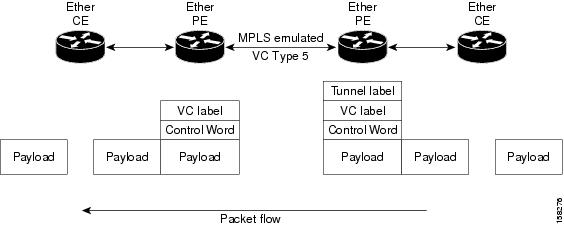
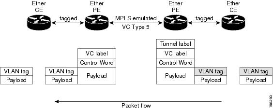
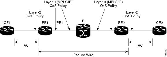
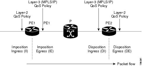
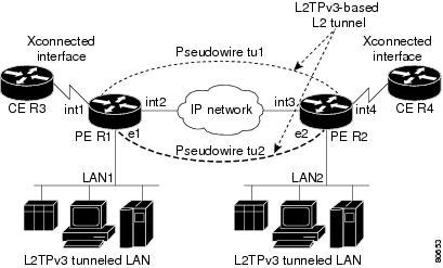
l2vpn 
pw-class ts
encapsulation l2tpv3 
protocol l2tpv3 
ttl <1-255>

Configuring Traffic Mirroring over L2TPv3 over IPv6 Tunnels: Example

This example associates an EFP to a monitor-session:

interface GigabitEthernet0/0/0/4.2 l2transport 
monitor-session customer-foo

Layer 2 SPAN is supported on L3 interfaces; however, the Layer 2 frame is mirrored:

interface GigabitEthernet0/0/0/4.2
ipv6 address <>
monitor-session customer-foo

SPAN is also supported on main interfaces.

interface GigabitEthernet0/4/0/3
l2transport
monitor-session customer-foo

This example creates the monitor-session globally:

monitor-session customer-foo
destination pseudowire

This example creates a cross-connect between the monitor-session and a L2TPv3 over IPv6 tunnel:

l2vpn
xconnect group span
p2p span-foo
monitor-session customer-foo
neighbor ipv6 1111:3333::cdef pw-id 1001
pw-class ts
source 1111:3333::abcd
l2tp static local cookie size 8 value 0xabcd 0x1234
l2tp static remote cookie size 8 value 0xcdef 0x5678

For more information on:

Configuring L2TPv3 over IPv4 Tunnels: Example

This section provides examples for:

Configuring a Dynamic L2TPv3 Pseudowire

Perform this task to configure a dynamic L2TPv3 pseudowire connecting to a remote IPv4 peer.

SUMMARY STEPS

  1. configure
  2. l2vpn
  3. xconnect group name
  4. p2p name
  5. interface type interface-path-id
  6. neighbor ipv4 ip-address pw-id number
  7. pw-class pw-class-name
  8. Use the commit or end command.

DETAILED STEPS


Step 1

configure

Example:
RP/0/RSP0/CPU0:router# configure

Enters the Global Configuration mode.

Step 2

l2vpn

Example:
RP/0/RSP0/CPU0:router(config)# l2vpn

Enter L2VPN configure submode.

Step 3

xconnect group name

Example:
RP/0/RSP0/CPU0:router(config-l2vpn)# xconnect group L2TPV3_V4_XC_GRP

Enter a name for the cross-connect group.

Step 4

p2p name

Example:
RP/0/RSP0/CPU0:router(config-l2vpn-xc)# p2p L2TPV3_P2P_1

Enters p2p configuration submode to configure point-to-point cross-connects.

Step 5

interface type interface-path-id

Example:

RP/0/RSP0/CPU0:router(config-l2vpn-xc-p2p)# interface GigabitEthernet 0/2/0/0/0.1

Specifies the interface type ID. The choices are:

  • GigabitEthernet
  • TenGigE
Step 6

neighbor ipv4 ip-address pw-id number

Example:
RP/0/RSP0/CPU0:router(config-l2vpn-xc-p2p)# neighbor ipv4 26.26.26.26 pw-id 100

Configures a pseudowire for a cross-connect.

Step 7

pw-class pw-class-name

Example:
RP/0/RSP0/CPU0:router(config-l2vpn-xc-p2p-pw)# pw-class L2TPV3_V4_CLASS

Enters pseudowire class submode to define a name for the cross-connect.

Step 8

Use the commit or end command.

commit - Saves the configuration changes and remains within the configuration session.

end - Prompts user to take one of these actions:

  • Yes - Saves configuration changes and exits the configuration session.
  • No - Exits the configuration session without committing the configuration changes.
  • Cancel - Remains in the configuration mode, without committing the configuration changes.

Configuring L2TPv3 Encapsulation and Protocol: Example

This example shows how to set the encapsulation and protocol for L2TPv3 tunnels:

configure
l2vpn
  pw-class L2TPV3_V4_CLASS
   encapsulation l2tpv3
    protocol l2tpv3 class L2TP-CLASS
    dfbit set
    ipv4 source 25.25.25.25
    cookie size 4
  !
!

Configuring L2TP Control-Channel Parameters: Example

The following example shows a typical L2TPv3 control-channel configuration:

configure
l2tp-class L2TP-CLASS
 authentication
 retransmit retries 5
 retransmit initial retries 10
 retransmit initial timeout max 5
 retransmit timeout max 6
 hidden
 password 7 1511021F07257A767B
 hello-interval 10
 digest hash MD5
!

Configuration Examples for EVPN-VPWS

Configuring EVPN-VPWS: Example

The following example shows how to configure EVPN-VPWS service.


RP/0/RSP0/CPU0:router# configure
RP/0/RSP0/CPU0:router(config)# l2vpn
RP/0/RSP0/CPU0:router(config-l2vpn)# xconnect group pw-he1
RP/0/RSP0/CPU0:router(config-l2vpn-xc)# p2p pw-ss
RP/0/RSP0/CPU0:router(config-l2vpn-xc-p2p)# interface gigabitethernet 0/1/0/9
RP/0/RSP0/CPU0:router(config-l2vpn-xc-p2p)# neighbor evpn evi 100 target 12 source 10

The following example shows how to configure EVPN-VPWS into PWHE interface.


RP/0/RSP0/CPU0:router# configure
RP/0/RSP0/CPU0:router(config)# l2vpn
RP/0/RSP0/CPU0:router(config-l2vpn)# xconnect group xg1
RP/0/RSP0/CPU0:router(config-l2vpn-xc)# p2p pwhe1
RP/0/RSP0/CPU0:router(config-l2vpn-xc-p2p)# interface PW-Ether 1
RP/0/RSP0/CPU0:router(config-l2vpn-xc-p2p)# neighbor evpn evi 2 target 20 source 20

Configuring an Access PW using EVPN-VPWS: Example

The following example shows how a bridge-domain can configure an access pseudowire using EVPN-VPWS.


RP/0/RSP0/CPU0:router# configure
RP/0/RSP0/CPU0:router(config)# l2vpn
RP/0/RSP0/CPU0:router(config-l2vpn)# bridge group bg1
RP/0/RSP0/CPU0:router(config-l2vpn-bg)# bridge-domain bd1
RP/0/RSP0/CPU0:router(config-l2vpn-bg-bd)# neighbor evpn evi 1 target 100