L2VPN and Ethernet Services Configuration Guide for Cisco ASR 9000 Series Routers, IOS XR Release 7.0.x
Bias-Free Language
The documentation set for this product strives to use bias-free language. For the purposes of this documentation set, bias-free is defined as language that does not imply discrimination based on age, disability, gender, racial identity, ethnic identity, sexual orientation, socioeconomic status, and intersectionality. Exceptions may be present in the documentation due to language that is hardcoded in the user interfaces of the product software, language used based on RFP documentation, or language that is used by a referenced third-party product. Learn more about how Cisco is using Inclusive Language.
This module provides conceptual and configuration information for IEEE 802.1ah Provider Backbone Bridge on Cisco ASR 9000
Series Routers. The IEEE 802.1ah standard (Ref [4]) provides a means for interconnecting multiple provider bridged networks
to build a large scale end-to-end Layer 2 provider bridged network.
The Cisco ASR 9000 Series Aggregation Services Routers now supports a scenario when the provider backbone bridge is a VPLS
network. You can now configure pseudowires in the PBB edge bridge domain and core bridge domain. In either type of bridge
domain, the pseudowire functionality remains the same as in the native bridge domain.
Feature History for Implementing IEEE 802.1ah Provider Backbone Bridge
Release
Modification
Release 3.9.1
This feature was introduced on Cisco ASR 9000 Series Routers
Release 4.3.0
Support was added for these features:
Provider Backbone Bridge VPLS
Multiple I-SID Registration Protocol Lite (MIRP Lite)
Release 4.3.2
Support was added for PBB-EVPN feature.
Release 5.1.2
Support was added for MMRP for PBB VPLS Flood Optimization
feature.
Release 6.3.2
Support for PBB-EVPN on nV Satellite access interface bundle over ICL
(Inter Chassis Link) bundle.
Note
PBB EVPN is supported only on Cisco ASR 9000 2nd generation Ethernet line cards and
Cisco ASR 9000 3rd generation Ethernet line cards.
PBB EVPN is not supported on Cisco ASR 9000 4th generation Ethernet line cards and
Cisco ASR 9000 5th generation Ethernet line cards.
Prerequisites for
Implementing 802.1ah Provider Backbone Bridge
This prerequisite
applies to implementing 802.1ah Provider Backbone Bridge:
You must be in a user group
associated with a task group that includes the proper task IDs. The command
reference guides include the task IDs required for each command.
If you suspect
user group assignment is preventing you from using a command, contact your AAA
administrator for assistance.
Information About
Implementing 802.1ah Provider Backbone Bridge
To implement 802.1ah,
you must understand these concepts:
Benefits of IEEE 802.1ah standard
The benefits of IEEE 802.1ah provider backbone bridges are as follows:
Increased service instance scalability—Enables a service provider to scale the number of services (service VLANs or service
instances) in a Provider Bridged Network (PBN).
MAC address scalability—Encapsulates the customer packet, including MAC addresses, into a new ethernet frame with new MAC
addresses (the backbone bridge MAC addresses). This eliminates the need for backbone core bridges to learn all MAC addresses
of every customer and also eases the load on backbone edge bridges.
VPLS pseudowire reduction and mesh scalability—The number of pseudowires in an IP/MPLS core can be significantly reduced.
This is because a single VPLS service can now transport several customer service instances thereby allowing a fewer number
of pseudowires in the IP/MPLS core to transport a large number of customer services.
Layer 2 backbone traffic engineering—Enables explicit controls for Layer 2 traffic engineering by separating service discrimination
function and moving it to the I-tags thereby leaving the backbone VLAN to be available for Layer 2 traffic engineering functions.
Point-to-point service scalability and optimization-enables point-to-point service implementation that includes multiple options
for service multiplexing as well as end point discovery.
Backbone flood traffic reduction—Since there are fewer MAC addresses in the core of the network, the amount of flood traffic
in the core network is reduced as there are fewer MAC addresses to be relearnt when MAC tables get flushed due to topology
changes.
IEEE 802.1ah Standard for Provider Backbone Bridging Overview
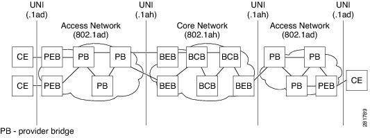
The IEEE 802.1ah Provider Backbone Bridge feature encapsulates or decapsulates end-user traffic on a Backbone Edge Bridge
(BEB) at the edge of the Provider Backbone Bridged Network (PBBN). A Backbone Core Bridge (BCB) based network provides internal
transport of the IEEE 802.1ah encapsulated frames within the PBBN. The following figure shows a typical 802.1ah PBB network.
Figure 1. IEEE 802.1ah Provider Backbone Bridge
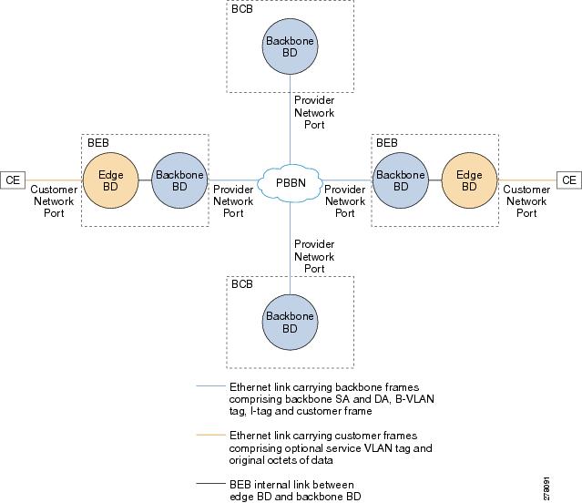
The following figure shows a typical provider backbone network topology.
Figure 2. Provider Back Bone Network Topology
Backbone Edge Bridges
Backbone edge bridges (BEBs) can contain either an I-Component or a B-Component. The I-Component maps service VLAN identifiers
(S-VIDs) to service instance identifiers (I-SIDs) and adds a provider backbone bridge (PBB) header without a backbone VLAN
tag (B-Tag). The B-Component maps I-SIDs to backbone VIDs (B-VIDs) and adds a PBB header with a B-Tag.
The IEEE 802.1ah standard specifies these three types of BEBs:
The B-BEB contains the B-Component of the MAC-in-MAC bridge. It validates the I-SIDs and maps the frames onto the backbone
VLAN (B-VLAN). It also switches traffic based on the B-VLANS within the core bridge.
The I-BEB contains the I-Component of the MAC-in-MAC bridge. It performs B-MAC encapsulation and inserts the I-SIDs based
on the provider VLAN tags (S-tags), customer VLAN tags (C-tags), or S-tag/C-tag pairs.
The IB-BEB contains one or more I-Components and a single B-Component interconnected through a LAN segment.
Note
Only IB-BEBs are supported on Cisco ASR 9000 Series Routers. Cisco IOS XR supports IB-BEB bridge type at the Edge node.
IB-BEB
The IB-BEB contains
both the I-Component and the B-Component. The bridge selects the B-MAC and
inserts the I-SID based on the provider VLAN tag (S-tag), the customer VLAN tag
(C-tag), or both the S-tag and the C-tag. It validates the I-SIDs and it
transmits and receives frames on the B-VLAN.
The IEEE 802.1ah on
Provider Backbone Bridges feature supports all services mandated by the IEEE
802.1ah standard and extends the services to provides these additional
functionalities:
S-Tagged Service:
In multiplexed environments
each S-tag maps to an I-SID and may be retained or removed.
In bundled environments
multiple S-tags map to the same I-SID and the S-tags must be retained.
C-Tagged Service:
In multiplexed environments
each C-tag maps to an I-SID and may be retained or removed.
In bundled environments
multiple C-tags map to the same I-SID and the C-tags must be retained.
S/C-Tagged Service:
In multiplexed environments
each S-tag/C-tag pair maps to an I-SID. The S-tag or the S-tag/C-tag pair may
be retained or removed.
In bundled environments
multiple S-tag/C-tags pairs map to the same I-SID and the S-tag/C-tag pair must
be retained.
Port-based Service
A port-based service
interface is delivered on a Customer Network Port (CNP). A port-based service
interface may attach to a C-VLAN Bridge, 802.1d bridge, router or end-station.
The service provided by this interface forwards all frames without an S-Tag
over the backbone on a single backbone service instance. A port-based interface
discards all frames with an S-Tag that have non-null VLAN IDs.
This example
shows how to configure a port-based service:
interface GigabitEthernet0/0/0/10.103 l2transport
encapsulation dot1q any
--> Creates
an EFP for C-tagged frames:
Note
To configure a
port-based service, all the above EFPs must be added to the same edge bridge
domain.
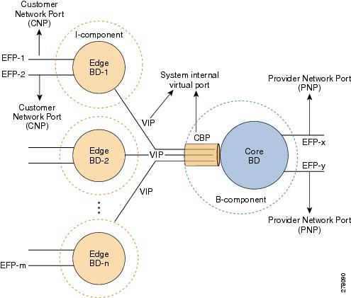
The following figure
shows the PBB bridge component topology on the Cisco ASR 9000 Series Routers.
Figure 3. PBB Bridge
Component Topology on Cisco ASR 9000 Series Routers
Multiple I-SID Registration Protocol Lite
The 802.1Qbe—Multiple I-SID Registration Protocol (MIRP) standard provides the ability to flush learned MAC address registration
entries held in the filtering database of an I-component on a per I-SID basis. The backbone service instance identifier (I-SID)
is a field in the backbone service instance tag which identifies the backbone service instance of a frame. MIRP defines mechanisms
for I-SID flushing, and has the required capabilities to handle topology changes that occur in networks attached to a provider
backbone bridged network. A backbone edge bridge (BEB) signals to other potentially affected BEBs, the need to alter certain
learned associations between customer MAC addresses and backbone MAC addresses. In the absence of MIRP, customer connections
across a provider backbone network can take several minutes to restore connectivity after a topology change in an access network.
In prior releases, PBB traffic was dropped for a MAC aging cycle when bridge forwarding topology changes occurred (due to
unavailable ports or spanning tree topology changes) in a PBB edge bridge domain. This resulted in severe limitations for
the use of PBB bridges.
Cisco ASR 9000 Series Aggregation Services Routers now support a simplified implementation of the MIRP protocol known as the
Multiple I-SID Registration Protocol Lite (MIRP-Lite). The MIRP-Lite feature enables detection of a topology change at a site.
A specially defined packet is flooded to all remote edge sites of the PBB network when a site detects a topology change. At
the sender site, I-SID of the I-component is placed in the I-TAG of the frame header to specify the I-SID that needs a MAC
flush. At the receiver site, each PBB edge switch performs I-SID checking. If the I-SID matches one of the I-components, the
MAC in the I-component is flushed.
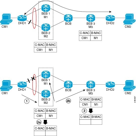
The use of MIRP in 802.1ah networks is illustrated in the following figure.
Figure 4. MIRP in 802.1ah Networks
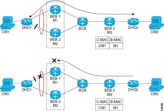
Device DHD1 is dual-homed to two 802.1ah backbone edge bridges (BEB1 and BEB2). Assume that initially the primary path is
through BEB1. In this configuration BEB3 learns that the host behind DHD1 (with MAC address CM1) is reachable via the destination
B-MAC M1. If the link between DHD1 and BEB1 fails and the host behind DHD1 remains inactive, the MAC cache tables on BEB3
still refer to the BEB1 MAC address even though the new path is now via BEB2 with B-MAC address M2. Any bridged traffic destined
from the host behind DHD2 to the host behind DHD1 is wrongly encapsulated with B-MAC M1 and sent over the MAC tunnel to BEB1,
where the traffic drops.
To circumvent the dropping of traffic when the link between DHD1 and BEB1 fails, BEB2 performs two tasks:
Flushes it’s own MAC address table for the service or services.
Requests the remote PE that receives the MIRP packet to clear it’s own MAC table. The MIRP message is transparent to the backbone
core bridges (BCBs). The MIRP message is processed on a BEB because only BCBs learn and forward, based on B-MAC addresses
and they are transparent to C-MAC addresses.
Note
MIRP triggers C-MAC address flushing for both native 802.1ah and PBB over VPLS.
The following figure shows the operation of the MIRP.
Figure 5. MIRP Operation
Provider Backbone
Bridging Ethernet VPN
The Provider
Backbone Bridging Ethernet VPN (PBB-EVPN) is a next generation L2VPN solution
that addresses resiliency and forwarding policy requirements. This feature also
introduces advanced multihoming options, support for multipath and user-defined
BGP policy capabilities to Ethernet L2VPNs. PBB-EVPN uses BGP for MAC address
distribution and learning over the packet-switched network (PSN). PBB-EVPN is a
combination of the capabilities of PBB and Ethernet VPN that addresses these
Carrier Ethernet and data center interconnect requirements:
All-active Redundancy and
Load Balancing
Simplified Provisioning and
Operation
Optimal Forwarding
Fast Convergence
MAC Address Scalability
Ethernet VPN
Ethernet Virtual
Private Network (EVPN) is a solution for secure and private connectivity of
multiple sites within an organization. The EVPN service extends the benefits of
Ethernet technology to the Wide Area Network (WAN). This service is delivered
over MPLS networks.
EVPN allows you to
manage routing over a virtual private network, providing complete control and
security. EVPN introduces a solution for multipoint L2VPN services, with
advanced multi-homing capabilities, using BGP for distributing customer or
client MAC address reachability information over the MPLS/IP network. EVPN
advertises each customer MAC address as BGP routes, therefore allowing BGP
policy control over MAC addresses.
Figure 6. MAC Distribution
in BGP (EVPN)
In the above figure,
the provider edge (PE) routers run multi-protocol BGP to advertise and learn
MAC addresses over MPLS. The customer MAC addresses are learnt in the data
plane over attachment circuits (links connecting customer devices to the PEs).
Then, the MAC addresses are distributed over MPLS using BGP with an MPLS label
identifying the EVPN instance.
PBB-EVPN
Overview
The PBB-EVPN solution
combines Ethernet Provider Backbone Bridging (PBB - IEEE 802.1ah) with Ethernet
VPN where, PEs perform as PBB Backbone Edge Bridge (BEB). The PEs receive
802.1Q Ethernet frames from their attachment circuits. These frames are
encapsulated in the PBB header and forwarded over the IP/MPLS core. On the
egress side (EVPN PE), the PBB header is removed after MPLS disposition, and
the original 802.1Q Ethernet frame is delivered to the customer equipment.
Figure 7. PBB-EVPN
Network
The PE routers perform
these functions:
Learns customer or
client MAC addresses (C-MACs) over the attachment circuits in the data-plane,
per normal bridge operation.
Learns remote
C-MAC to backbone MAC (B-MAC) bindings in the data-plane from traffic ingress
from the core.
Advertises local
B-MAC address reachability information in BGP to all other PE nodes in the same
set of service instances. Note that every PE has a set of local B-MAC addresses
that uniquely identify the device.
Builds a
forwarding table from the received remote BGP advertisements, associating
remote B-MAC addresses with remote PE IP addresses.
PBB-EVPN scales well
for large network with millions of customer MAC addresses by constraining
customer MAC address in access. Only B-MAC addresses are advertised in core,
making the number of BGP routes exchanged manageable.
For PBB EVPN, the B-MAC
flush is per B-MAC per Ethernet VPN Instance (EVI).
EVPN
Instance
E-VPN Instance (EVI)
identifies a VPN in the MPLS/IP network. There can only be one EVI per core
bridge.
Ethernet
Segment
Ethernet Segment is
a site connected to one or more PEs. The Ethernet Segment could be a single
device (i.e. Customer Edge (CE)) or an entire network, such as:
Single-Homed Device (SHD)
Multi-Homed Device (MHD) using Ethernet Multi-chassis Link Aggregation Group
Single-Homed Network (SHN)
Multi-Homed Network (MHN)
The Ethernet
segment is uniquely identified by a 10-byte global Ethernet Segment Identifier
(ESI).
The ESI format is RFC 7432 complaint. The ESI value depends on the ESI type. Currently, only ESI type 0 and 1 are supported.
The following table shows the ESI format based on the ESI type.
ESI Type
Explanation
ESI Format
Type 0
Arbitrary ESI value based on configuration
1 octet ESI Type 0x00
9 octet ESI value
Type 1
Auto-generated ESI value based on LACP
1 octet ESI Type 0x01
6 octet CE LACP MAC address
2 octet CE LACP Port Key
1 octet value of 0x00
The following figure
illustrates an example of Ethernet segment and ESI.
Figure 8. Ethernet
Segment
PBB-EVPN BGP
Routes
PBB-EVPN defines a
single new BGP network layer reachability information (NLRI) used to advertise
different types of routes along with new attributes.
Designated
Forwarder Election
The Designated
Forwarder (DF) election mechanism is used to determine a designated forwarder
in dual-homed or multi-homed devices or networks. The election is performed on
a per service basis. The DF filtering function for MHN differs from that for
MHD in:
Directionality—DF filtering for MHN is applied for traffic both ingress and egress on the access-facing Ethernet interfaces;
whereas, DF filtering for MHD is applied only to traffic that egress the access-facing interfaces.
Traffic Type—DF filtering for MHN impacts both unicast as well as flooded multi-destination traffic; whereas, DF filtering
for MHD only applies to flooded multi-destination traffic.
The following
figure shows the various DF filtering rules for MHN and MHD.
Figure 9. DF Filtering
Comparison for MHN/MHD
Access
Auto-Sensing
PEs connected to a
multi-homed or dual-homed device may support active-active per flow also known
as flow-based load balancing. PE services CEs via physical or bundle ports. An
Ethernet segment identifier is assigned per port. This value is calculated from
the connected CE using information such as, CE system priority, CE system ID
and CE port key. The PE must auto-detect the access topology to determine the
type of load balancing. The load balancing could be active-active per flow
load-balancing, per service load-balancing or simply no load balancing.
MMRP for PBB VPLS
Flood Optimization
In a PBB network,
traffic (unknown unicast, multicast, or broadcast) is flooded to all the PE
devices in the network even if the devices do not host the service instance to
which the traffic is destined.
The Multiple MAC
Registration Protocol (MMRP) for PBB VPLS Flood Optimization feature optimizes
the impact of the flooded traffic on PE devices by sending the traffic only to
the PE devices interested in a particular service instance.
In a PBB over VPLS
network, traffic between the PE devices flows over MPLS pseudo-wires that
connect all the PE devices in a full mesh network topology.
Provider Back Bone Network Topology figure illustrates a typical 802.1ah
PBB network.
For every I-SID
(Service Instance VLAN ID) there is a corresponding multicast MAC address
called the group B-MAC address, which is derived based on the I-SID. The group
B-MAC address is used as the destination address in the outer MAC header when
propagating flooded traffic across the provider backbone.
The MMRP is used by
the PE devices to inform each other about the set of group B-MAC addresses
corresponding to the I-SIDs of the service instances they host. This enables
each device to determine which set of pseudo-wires flooded traffic should be
forwarded on, that is, those pseudo-wires on which an MMRP registration has
been received for the group B-MAC address corresponding to the I-SID.
Note
The PBB-VPLS
flood optimization feature is enabled only on PBB-VPLS network and not on PBB
over Ethernet network.
Configuring PBB-VPLS Flood Optimization
To configure the PBB-VPLS flood optimization feature, do the following:
Enabling PBB-VPLS
Flood Optimization on PBB Core Bridge
Perform this task
to enable PBB-VPLS flood optimization on PBB core bridge.
SUMMARY STEPS
configure
l2vpn
bridgegroupbridge-group-name
bridge-domaindomain-name
pbbcore
mmrp-flood-optimization
Use the
commit or
end command.
DETAILED STEPS
Step 1
configure
Example:
RP/0/RSP0/CPU0:router# configure
Enters
Global Configuration mode.
Step 2
l2vpn
Example:
RP/0/RSP0/CPU0:router(config)# l2vpn
Enters L2VPN
configuration mode.
Step 3
bridgegroupbridge-group-name
Example:
RP/0/RSP0/CPU0:router(config-l2vpn)# bridge group pbb
Enters
configuration mode for the named bridge group. This command creates a new
bridge group or modifies the existing bridge group if it already exists. A
bridge group organizes bridge domains.
Enters
configuration mode for the named bridge domain. This command creates a new
bridge domain or modifies the existing bridge domain if it already exists.
Step 5
pbbcore
Example:
RP/0/RSP0/CPU0:router(config-l2vpn-bg-bd)# pbb core
Configures the
bridge domain as PBB core and enters the PBB core configuration submode.
This command
also creates an internal port known as Customer bridge port (CBP).
All the
interfaces (bridge ports) under this bridge domain are treated as the provider
network ports (PNP).
Enables
flooding of traffic to the entire core bridge when the PBB-VPLS Flood
Optimization feature is enabled on the core bridge.
Step 8
Use the
commit or
end command.
commit -
Saves the configuration changes and remains within the configuration session.
end - Prompts
user to take one of these actions:
Yes - Saves
configuration changes and exits the configuration session.
No - Exits the
configuration session without committing the configuration changes.
Cancel - Remains in the
configuration mode, without committing the configuration changes.
How to Implement 802.1ah Provider Backbone Bridge
This section contains these procedures:
Restrictions for
Implementing 802.1ah Provider Backbone Bridge
The following features
are not supported:
Cross-connect based point to
point services over MAC-in-MAC
One Edge bridge to multiple
Core bridge mapping
I type backbone edge bridge
(I-BEB) and B type backbone edge bridge (B-BEB)
IEEE 802.1ah over VPLS
Multiple source B-MAC
addresses per chassis
Direct encapsulation of
802.1ah formatted packets natively over an MPLS LSP encapsulation
The following
additional restriction applies when implementing Provider Backbone Bridge
Ethernet VPN (PBB-EVPN):
The Provider Edge
and Route Reflector routers must run software supporting the same IETF draft
version of L2VPN Ethernet VPN (EVPN). Due to the differences in BGP Network
Layer Reachability Information (NLRI) encoding, later draft versions are not
backward compatible with earlier ones. The following table shows the supported
draft for various Cisco IOS XR software releases.
Cisco IOS XR software release
Supported L2VPN EVPN draft
version
draft-ietf-l2vpn-evpn-04
draft-ietf-l2vpn-evpn-06
5.1.1 and older releases
✓
—
5.2.0
✓
—
5.1.2 and later releases except 5.2.0
—
✓
Configuring Ethernet
Flow Points on CNP and PNP Ports
Perform this task to
configure an Ethernet flow point (EFP) on the customer network port (CNP) or
the provider network port (PNP).
encapsulation dot1qvlan-id or
encapsulation dot1advlan-id
or
encapsulation dot1advlan-iddot1qvlan-id
Example:
RP/0/RSP0/CPU0:router(config-subif)# encapsulation dot1q 100
or
encapsulation dot1ad 100
or
encapsulation dot1ad 100 dot1q 101
Assigns the
matching VLAN ID and Ethertype to the interface
Step 4
Use the
commit or
end command.
commit - Saves the configuration changes and
remains within the configuration session.
end - Prompts user to take one of these actions:
Yes - Saves
configuration changes and exits the configuration session.
No - Exits the
configuration session without committing the configuration changes.
Cancel - Remains in the
configuration mode, without committing the configuration changes.
Configuring PBB Edge
Bridge Domain and Service Instance ID
Perform this task to
configure a PBB edge domain and the service ID.
Note
To configure the
PBB feature, login with admin user privileges and issue the
hw-module
profile feature l2 command to select an ASR 9000 Ethernet line card
ucode version that supports the PBB feature. The PBB feature will not be
supported on the ASR 9000 Ethernet line card unless you make this
configuration. For more information on configuring the feature profile, refer
to the
Cisco ASR 9000
Series Aggregation Services Router System Management Configuration
Guide.
SUMMARY STEPS
configure
l2vpn
bridge groupbridge-group-name
bridge-domaindomain-name
interfacetype
interface-path-id.subinterface
pbb edge i-sidservice-id
core-bridgecore-bridge-name
Use the
commit or
end command.
DETAILED STEPS
Step 1
configure
Example:
RP/0/RSP0/CPU0:router# configure
Enters the
Global Configuration mode.
Step 2
l2vpn
Example:
RP/0/RSP0/CPU0:router(config)# l2vpn
Enters L2VPN
configuration mode.
Step 3
bridge groupbridge-group-name
Example:
RP/0/RSP0/CPU0:router(config-l2vpn)# bridge group pbb
Enters
configuration mode for the named bridge group. This command creates a new
bridge group or modifies the existing bridge group if it already exists. A
bridge group organizes bridge domains.
Enters
configuration mode for the named bridge domain. This command creates a new
bridge domain or modifies the existing bridge domain, if it already exists.
Assigns the
matching VLAN ID and Ethertype to the interface. This EFP is considered as the
CNP for the Edge bridge.
Step 6
pbb edge i-sidservice-id
core-bridgecore-bridge-name
Example:
RP/0/RSP0/CPU0:router(config-l2vpn-bg-bd)# pbb edge i-sid 1000 core-bridge pbb-core
Configures the
bridge domain as PBB edge with the service identifier and the assigned core
bridge domain, and enters the PBB edge configuration submode.
This command
also creates the Virtual instance port (VIP) that associates the PBB Edge
bridge domain to the specified Core bridge domain.
All the
interfaces (bridge ports) under this bridge domain are treated as the customer
network ports (CNP).
Step 7
Use the
commit or
end command.
commit -
Saves the configuration changes and remains within the configuration session.
end - Prompts
user to take one of these actions:
Yes - Saves
configuration changes and exits the configuration session.
No - Exits the
configuration session without committing the configuration changes.
Cancel - Remains in the
configuration mode, without committing the configuration changes.
Configuring the PBB
Core Bridge Domain
Perform this task to
configure the PBB core bridge domain.
SUMMARY STEPS
configure
l2vpn
bridge groupgroup-name
bridge-domaindomain-name
interfacetype interface-path-id.subinterface
pbb
core
Use the
commit or
end command.
DETAILED STEPS
Step 1
configure
Example:
RP/0/RSP0/CPU0:router# configure
Enters
Global Configuration mode.
Step 2
l2vpn
Example:
RP/0/RSP0/CPU0:router(config)# l2vpn
Enters L2VPN
configuration mode.
Step 3
bridge groupgroup-name
Example:
RP/0/RSP0/CPU0:router(config-l2vpn)# bridge group pbb
Enters
configuration mode for the named bridge group. This command creates a new
bridge group or modifies the existing bridge group, if it already exists. A
bridge group organizes bridge domains.
Enters
configuration mode for the named bridge domain. This command creates a new
bridge domain or modifies the existing bridge domain if it already exists.
Assigns the
matching VLAN ID and Ethertype to the interface.
Step 6
pbb
core
Example:
RP/0/RSP0/CPU0:router(config-l2vpn-bg-bd)# pbb core
Configures the
bridge domain as PBB core and enters the PBB core configuration submode.
This command
also creates an internal port known as Customer bridge port (CBP).
All the
interfaces (bridge ports) under this bridge domain are treated as the provider
network ports (PNP).
Step 7
Use the
commit or
end command.
commit - Saves the configuration changes
and remains within the configuration session.
end - Prompts user to take one of these
actions:
Yes - Saves
configuration changes and exits the configuration session.
No - Exits the
configuration session without committing the configuration changes.
Cancel -
Remains in the configuration mode, without committing the configuration
changes.
Configuring Backbone
VLAN Tag under the PBB Core Bridge Domain
Perform this task to
configure the backbone VLAN tag under the PBB core bridge domain.
SUMMARY STEPS
configure
l2vpn
bridge groupbridge-group-name
bridge-domaindomain-name
interfacetype
interface-path-id.subinterface
interfacetype
interface-path-id. subinterface
pbb core
rewrite ingress tag push
dot1advlan-idsymmetric
Use the
commit or
end command.
DETAILED STEPS
Step 1
configure
Example:
RP/0/RSP0/CPU0:router# configure
Enters the
Global Configuration mode.
Step 2
l2vpn
Example:
RP/0/RSP0/CPU0:router(config)# l2vpn
Enters L2VPN
configuration mode.
Step 3
bridge groupbridge-group-name
Example:
RP/0/RSP0/CPU0:router(config-l2vpn)# bridge group pbb
Enters
configuration mode for the named bridge group. This command creates a new
bridge group or modifies the existing bridge group if it already exists. A
bridge group organizes bridge domains.
Enters
configuration mode for the named bridge domain. This command creates a new
bridge domain or modifies the existing bridge domain if it already exists.
Adds an
interface to a bridge domain that allows packets to be forwarded and received
from other interfaces that are part of the same bridge domain. The interface
now becomes an attachment circuit on this bridge domain.
Step 7
pbb core
Example:
RP/0/RSP0/CPU0:router(config-l2vpn-bg-bd)# pbb core
Configures the
bridge domain as PBB core and enters the PBB core configuration submode.
This command
also creates an internal port known as Customer bridge port (CBP).
All the
interfaces (bridge ports) under this bridge domain are treated as the provider
network ports (PNP).
Step 8
rewrite ingress tag push
dot1advlan-idsymmetric
Example:
RP/0/RSP0/CPU0:router(config-l2vpn-bg-bd-pbb-core)# end
Configures the
backbone VLAN tag in the Mac-in-MAC frame and also, sets the tag rewriting
policy.
Note
All PNPs in a
Core bridge domain use the same backbone VLAN.
Step 9
Use the
commit or
end command.
commit -
Saves the configuration changes and remains within the configuration session.
end - Prompts
user to take one of these actions:
Yes - Saves
configuration changes and exits the configuration session.
No - Exits the
configuration session without committing the configuration changes.
Cancel - Remains in the
configuration mode, without committing the configuration changes.
Configuring Backbone
Source MAC Address
The backbone source
MAC address (B-SA) is a unique address for a backbone network. Each Cisco ASR
9000 Series Router has one backbone source MAC address. If B-SA is not
configured, then the largest MAC in the EEPROM is used as the PBB B-SA.
Note
The backbone
source MAC address configuration is optional. If you do not configure the
backbone source MAC address, the Cisco ASR 9000 Series Routers allocate a
default backbone source MAC address from the chassis backplane MAC pool.
Perform this task to
configure the backbone source MAC address.
commit - Saves the configuration changes and
remains within the configuration session.
end - Prompts
user to take one of these actions:
Yes - Saves
configuration changes and exits the configuration session.
No - Exits the
configuration session without committing the configuration changes.
Cancel - Remains in the
configuration mode, without committing the configuration changes.
Configuring Unknown
Unicast Backbone MAC under PBB Edge Bridge Domain
Perform this task to
configure the unknown unicast backbone MAC under the PBB edge bridge domain.
SUMMARY STEPS
configure
l2vpn
bridge groupbridge-group-name
bridge-domaindomain-name
interfacetype
interface-path-id.subinterface
pbb edge i-sidservice-id
core-bridgecore-bridge-name
unknown-unicast-bmacmac-address
Use the
commit or
end command.
DETAILED STEPS
Step 1
configure
Example:
RP/0/RSP0/CPU0:router# configure
Enters the
Global Configuration mode.
Step 2
l2vpn
Example:
RP/0/RSP0/CPU0:router(config)# l2vpn
Enters L2VPN
configuration mode.
Step 3
bridge groupbridge-group-name
Example:
RRP/0/RSP0/CPU0:router(config-l2vpn)# bridge group pbb
Enters
configuration mode for the named bridge group. This command creates a new
bridge group or modifies the existing bridge group if it already exists. A
bridge group organizes bridge domains.
Enters
configuration mode for the named bridge domain. This command creates a new
bridge domain or modifies the existing bridge domain if it already exists.
Assigns the
matching VLAN ID and Ethertype to the interface.
Step 6
pbb edge i-sidservice-id
core-bridgecore-bridge-name
Example:
RP/0/RSP0/CPU0:router(config-l2vpn-bg-bd)# pbb edge i-sid 1000 core-bridge pbb-core
Configures the
bridge domain as PBB edge with the service identifier and the assigned core
bridge domain and enters the PBB edge configuration submode.
This command
also creates the Virtual instance port (VIP) that associates the PBB Edge
bridge domain to the specified Core bridge domain.
All the
interfaces (bridge ports) under this bridge domain are treated as the customer
network ports (CNP).
On Trident line cards, once you configure the unknown unicast
BMAC, the BMAC is used to forward customer traffic with multicast, broadcast
and unknown unicast destination MAC address.
Step 8
Use the
commit or
end command.
commit -
Saves the configuration changes and remains within the configuration session.
end - Prompts
user to take one of these actions:
Yes - Saves
configuration changes and exits the configuration session.
No - Exits the
configuration session without committing the configuration changes.
Cancel - Remains in the
configuration mode, without committing the configuration changes.
Configuring Static
MAC addresses under PBB Edge Bridge Domain
Perform this task to
configure the static MAC addresses under the PBB edge bridge domain.
SUMMARY STEPS
configure
l2vpn
bridge groupbridge-group-name
bridge-domaindomain-name
interfacetype interface-path-id.subinterface
interfacetype interface-path-id.subinterface
pbb edge
i-sidservice-idcore-bridgecore-bridge-name
RP/0/RSP0/CPU0:router(config-l2vpn)#bridge group pbb
Enters
configuration mode for the named bridge group. This command creates a new
bridge group or modifies the existing bridge group if it already exists. A
bridge group organizes bridge domains.
Enters
configuration mode for the named bridge domain. This command creates a new
bridge domain or modifies the existing bridge domain if it already exists.
Adds an
interface to a bridge domain that allows packets to be forwarded and received
from other interfaces that are part of the same bridge domain. The interface
now becomes an attachment circuit on this bridge domain.
Step 7
pbb edge
i-sidservice-idcore-bridgecore-bridge-name
Configures the
bridge domain as PBB edge with the service identifier and the assigned core
bridge domain and enters the PBB edge configuration submode.
This command
also creates the Virtual instance port (VIP) that associates the PBB Edge
bridge domain to the specified Core bridge domain.
All the
interfaces (bridge ports) under this bridge domain are treated as the customer
network ports (CNP).
Configures the
static CMAC to BMAC mapping under the PBB Edge submode.
Step 9
Use the
commit or
end command.
commit - Saves the configuration changes
and remains within the configuration session.
end - Prompts user to take one of these
actions:
Yes - Saves
configuration changes and exits the configuration session.
No - Exits the
configuration session without committing the configuration changes.
Cancel -
Remains in the configuration mode, without committing the configuration
changes.
Configuring PBB
VPLS
Perform these tasks
to configure PBB VPLS:
Configuring Access
Pseudowire in I-Component
Perform this task to
configure the static MAC addresses under the PBB edge bridge domain.
SUMMARY STEPS
configure
l2vpn
bridge groupbridge-group-name
bridge-domaindomain-name
mac withdraw state-down
exit
interfacetype
interface-path-id.subinterface
interfacetype
interface-path-id.subinterface
neighbor {
A.B.C.D }
pw-idvalue
exit
pbb edge i-sidservice-idcore-bridgecore-bridge-name
Use the
commit or
end command.
DETAILED STEPS
Step 1
configure
Example:
RP/0/RSP0/CPU0:router# configure
Enters the
Global Configuration mode.
Step 2
l2vpn
Example:
RP/0/RSP0/CPU0:router(config)# l2vpn
Enters L2VPN
configuration mode.
Step 3
bridge groupbridge-group-name
Example:
RP/0/RSP0/CPU0:router(config-l2vpn)# bridge group pbb
Enters bridge
group configuration mode. This command creates a new bridge group or modifies
the existing bridge group if it already exists. A bridge group organizes bridge
domains.
Adds an
interface to a bridge domain that allows packets to be forwarded and received
from other interfaces that are part of the same bridge domain. The interface
now becomes an attachment circuit on this bridge domain.
pbb edge i-sidservice-idcore-bridgecore-bridge-name
Example:
RP/0/RSP0/CPU0:router(config-l2vpn-bg-bd)# pbb edge i-sid 1000 core-bridge pbb-core
Configures the
bridge domain as PBB edge with the service identifier and the assigned core
bridge domain and enters the PBB edge configuration submode.
All the
interfaces (bridge ports) under this bridge domain are treated as the customer
network ports (CNP).
Step 12
Use the
commit or
end command.
commit -
Saves the configuration changes and remains within the configuration session.
end - Prompts
user to take one of these actions:
Yes - Saves
configuration changes and exits the configuration session.
No - Exits the
configuration session without committing the configuration changes.
Cancel - Remains in the
configuration mode, without committing the configuration changes.
Configuring Core
Pseudowire in B-Component
Perform this task to
configure the static MAC addresses under the PBB edge bridge domain.
SUMMARY STEPS
configure
l2vpn
bridge groupbridge-group-name
bridge-domaindomain-name
vfi {
vfi-name }
neighbor {
A.B.C.D } {
pw-idvalue }
Use the
commit or
end command.
DETAILED STEPS
Step 1
configure
Example:
RP/0/RSP0/CPU0:router# configure
Enters the
Global Configuration mode.
Step 2
l2vpn
Example:
RP/0/RSP0/CPU0:router(config)# l2vpn
Enters L2VPN
configuration mode.
Step 3
bridge groupbridge-group-name
Example:
RP/0/RSP0/CPU0:router(config-l2vpn)#bridge group pbb
Enters
configuration mode for the named bridge group. This command creates a new
bridge group or modifies the existing bridge group if it already exists. A
bridge group organizes bridge domains.
Enters
configuration mode for the named bridge domain. This command creates a new
bridge domain or modifies the existing bridge domain if it already exists.
Enters bridge
group domain configuration mode. This command creates a new bridge domain.
Step 5
pbb core
Example:
RP/0/RSP0/CPU0:router(config-l2vpn-bg-bd)# pbb core
Configures the
bridge domain as PBB core and enters the PBB core configuration submode.
This command
also creates an internal port known as Customer bridge port (CBP). All the
interfaces (bridge ports) under this bridge domain are treated as the provider
network ports (PNP).
Step 6
evpn evievi_id
Example:
RP/0/RSP0/CPU0:router(config-l2vpn-bg-bd-pbb-core)# evpn evi 100
Enters EVPN
configuration mode and configures the Ethernet VPN ID. The EVI ID range is from
1 to 65534.
Step 7
Use the
commit or
end command.
commit -
Saves the configuration changes and remains within the configuration session.
end - Prompts
user to take one of these actions:
Yes - Saves
configuration changes and exits the configuration session.
No - Exits the
configuration session without committing the configuration changes.
Cancel - Remains in the
configuration mode, without committing the configuration changes.
Configuring PBB Edge
Bridge Domains
As a pre-requisite, a
PBB-EVPN provider edge (PE) must be configured with PBB Edge Bridge Domains
which in one side are associated to ethernet flow points matching traffic from
access interfaces and on the other side are linked to PBB Core Bridge Domains
for traffic forwarding through the core.
Explicit
configuration of Ethernet Segment parameters such as ESI and service carving
behaviors (manual or dynamic) is required only for Dual Homed scenarios with
Active/Active per Service load-balancing.
Note
By default, Dual
Homed scenarios with Active/Active per Flow load-balancing auto-sense ESI
values from CE's LACP information.
Note
PBB-EVPN
configuration allows to create only 24 ICCP-groups.
Perform this task to
configure the EVPN Ethernet segment.
Flush-again
timer (for AApS only): When a MAC flush is sent, usually at the end of the
programming timer expiration, a flush-again timer is started for the
flush-again timer value. When it expires, another MAC flush message (MVRP or
STP-TCN) is sent to the CE. This timer can be configured per segment-interface.
Range: 0 to
120 seconds, 0 means disabled
Default: 60
seconds
Peering
timer: Once all conditions are met to advertise to BGP, the PE waits for the
peering timer value before advertising its RT, ESI and, Local MAC if it is
Single-Home.
Range: 0 to
300 seconds, 0 means disabled
Default: 45
seconds
Programming
timer: Indicated time required by the HW to apply the carving results. At the
end of the programming timer expiration, the next Ethernet Segment route object
will be processed.
Range: 0 to
100000 microseconds
Default:
1500 microseconds
Recovery
timer (for AApS only): Once the interface is up, the PE waits for the recovery
timer value in order to allow the CE running STP protocol to converge. This
timer can be configured per segment-interface.
Range: 20 to
3600 seconds
Default: 20
seconds
Note
Changing
timers is only useful for scale configurations.
Step 4
Use the
commit or
end command.
commit -
Saves the configuration changes and remains within the configuration session.
end - Prompts
user to take one of these actions:
Yes - Saves
configuration changes and exits the configuration session.
No - Exits the
configuration session without committing the configuration changes.
Cancel - Remains in the
configuration mode, without committing the configuration changes.
Configuring EVPN
Timers Per Ethernet Segment and CE flushing mechanism
Perform this task to
configure per Ethernet segment timers.
Flush-again
timer (for AApS only): When a MAC flush is sent, usually at the end of the
programming timer expiration, a flush-again timer is started for the
flush-again timer value. When it expires, another MAC flush message (MVRP or
STP-TCN) is sent to the CE. This timer can be configured per segment-interface.
Range: 0 to
120 seconds, 0 means disabled
Default: 60
seconds
Recovery
timer (for AApS only): Once the interface is up, the PE waits for the recovery
timer value in order to allow the CE running STP protocol to converge. This
timer can be configured per segment-interface.
Range: 20 to
3600 seconds
Default: 20
seconds
Note
Changing
timers is only useful for scale configurations.
Step 7
Use the
commit or
end command.
commit -
Saves the configuration changes and remains within the configuration session.
end - Prompts
user to take one of these actions:
Yes - Saves
configuration changes and exits the configuration session.
No - Exits the
configuration session without committing the configuration changes.
Cancel - Remains in the
configuration mode, without committing the configuration changes.
Configuring
Multichassis Link Aggregation
Multichassis Link
Aggregation (MCLAG) is used in scenarios involving Multi Homed Devices. You
must create an ICCP redundancy group in order to specify relevant MLACP
parameters, such as,
mlacp system mac, mlacp system priority, mlacp node
id and backbone interfaces.
Note
Even though the
redundancy group is created under the
redundancy-iccp-group sub-mode, the solution
does not rely on an actual ICCP session between PEs connected to the same site.
The mode singleton command has been introduced to alert ICCP module.
For more information
on configuring MCLAG, refer to the Configuring Link Bundling on the Cisco ASR
9000 Series Router module in the
Cisco ASR 9000 Series Aggregation Services Router Interface and
Hardware Component Configuration Guide.
Configuring BGP
Routing Process
A prerequisite of
PBB-EVPN involves enabling the new EVPN address family under the BGP routing
process and under BGP neighbor submode. For more information on BGP, refer to
the
Implementing
BGP module in the
Cisco ASR
9000 Series Aggregation Services Router Routing Configuration Guide.
Perform this task to
enable EVPN address family under BGP routing process and BGP neighbor submode.
SUMMARY STEPS
configure
router bgpasn_id
address-family l2vpn
evp
exit
neighborpeer_ip_add
address-family l2vpn
evpn
address-family l2vpn
evpn
Use the
commit or
end command.
DETAILED STEPS
Step 1
configure
Example:
RP/0/RSP0/CPU0:router# configure
Enters the
Global Configuration mode.
Step 2
router bgpasn_id
Example:
RP/0/RSP0/CPU0:router(config)# router bgp 100
Specifies the
BGP AS number and enters the BGP configuration mode, allowing you to configure
the BGP routing process.
Enables EVPN
address family under BGP routing process and enters EVPN address family
configuration submode.
Step 8
Use the
commit or
end command.
commit -
Saves the configuration changes and remains within the configuration session.
end - Prompts
user to take one of these actions:
Yes - Saves
configuration changes and exits the configuration session.
No - Exits the
configuration session without committing the configuration changes.
Cancel - Remains in the
configuration mode, without committing the configuration changes.
PBB EVPN Flow Label
The PBB EVPN Flow Label feature enables provider (P) routers to use flow-based load balancing to forward traffic between the
provider edge (PE) devices. A flow label is created based on indivisible packet flows entering an imposition PE, and it is
inserted as the lower most label in the packet. P routers use flow label for load balancing to provide better traffic distribution
across ECMP paths or link-bundled paths in the core. A flow is identified either by the source and destination IP address
and layer 4 source and destination ports of the traffic, or the source and destination MAC address of the traffic.
Consider the following topology where PBB EVPN imposition router, PE1, adds a flow label in the EVPN traffic. The PBB EVPN
disposition router, PE2, allows mixed types of traffic; some have flow label, others do not. The P router use flow label to
load balance the traffic between the PEs . PE2 ignores flow label in traffic, and uses one EVPN label for all unicast traffic.
Figure 10. PBB EVPN Flow Label
Configure PBB EVPN Flow Label
Perform these tasks to configure PBB EVPN Flow Label feature.
This section shows PBB EVPN Flow Label running configuration.
l2vpn
 bridge group PBB
  bridge-domain EDGE
   interface Bundle-Ether1.10
   pbb edge i-sid 1010 core-bridge CORE

  bridge-domain CORE
   pbb-core
     evpn evi 10

evpn
 evi 10
  load-balancing
   flow-label static

router bgp 20
address-family l2vpn evpn
Verification
Verify PBB EVPN Flow Label configuration.
RP/0/RSP0/CPU0:router#show evpn evi vpn-id 10 detail
EVI        Bridge Domain                Type
---------- ---------------------------- -------
10         EVPN                         PBB
   Unicast Label  : 24001
   Multicast Label: 24002
   Flow Label: Y
   RD Config: none
   RD Auto  : (auto) 1.1.1.1:10
   RT Auto  : 1:10
   Route Targets in Use           Type
   ------------------------------ -------
   1:10                           Import
   1:10                           Export
Configuration Examples for Implementing 802.1ah Provider Backbone Bridge
This section provides these configuration examples:
Configuring Ethernet Flow Points: Example
This example shows how to configure Ethernet flow points:
config
interface GigabitEthernet0/0/0/10.100 l2transport
 encapsulation dot1q 100
or
 encapsulation dot1ad 100
or
 encapsulation dot1ad 100 dot1q 101
Configuring PBB Edge Bridge Domain and Service Instance ID: Example
This example shows how to configure the PBB edge bridge domain:
config
l2vpn
 bridge group PBB
  bridge-domain PBB-EDGE
  interface GigabitEthernet0/0/0/38.100
  !
  interface GigabitEthernet0/2/0/30.150
  !
  pbb edge i-sid 1000 core-bridge PBB-CORE
   !
 !
!
Configuring PBB Core Bridge Domain: Example
This example shows how to configure the PBB core bridge domain:
config
l2vpn
 bridge group PBB
  bridge-domain PBB-CORE
  interface G0/5/0/10.100
  !
  interface G0/2/0/20.200
  !
   pbb core
   !
 !
!
Configuring Backbone VLAN Tag: Example
This example shows how to configure the backbone VLAN tag:
config
l2vpn
 bridge group PBB
  bridge-domain PBB-CORE
  interface G0/5/0/10.100
  !
  interface G0/2/0/20.200
  !
   pbb core
    rewrite ingress tag push dot1ad 100 symmetric
   !
 !
!
Configuring Backbone Source MAC Address: Example
This example shows how to configure the backbone source MAC address:
config
l2vpn
 pbb
  backbone-source-mac 0045.1200.04
 !
!
Configuring Static Mapping and Unknown Unicast MAC Address under the PBB Edge Bridge Domain
This example shows how to configure static mapping and unknown unicast MAC address under the PBB edge bridge domain:
config
l2vpn
 bridge group PBB
  bridge-domain PBB-EDGE
  interface GigabitEthernet0/0/0/38.100
  !
  interface GigabitEthernet0/2/0/30.150
  !
  pbb edge i-sid 1000 core-bridge PBB-CORE
   static-mac-address 0033.3333.3333 bmac 0044.4444.4444
   unknown-unicast-bmac 0123.8888.8888
   !
 !
!
Configuring PBB-VPLS: Example
This example shows you how to configure PBB VPLS.
Configuring Access Pseudowire in I-component
l2vpn
  bridge group PBB
    bridge-domain PBB-EDGE
      mac withdraw state-down ------ can be used with MIRP, optional
      interface GigabitEthernet0/0/0/38.100
      interface GigabitEthernet0/2/0/30.150
      neighbor 10.10.10.1 pw-id 1010 ------- configures access PW
      !
      pbb edge i-sid 1200 core-bridge PBB-CORE
   !
 !
!
The MIRP feature is enabled by default. However, MIRP packets are
sent when the attachment circuit is not functional and you have configured
macwithdrawstate-downas shown:
l2vpn
  bridge group PBB
    bridge-domain PBB-EDGE
mac withdraw state-down
However, if you have not configured mac withdraw state-down, then
MIRP packets are sent when the attachment circuit is functional.
Configuring
PBB-EVPN: Example
This section provides examples for:
PBB-EVPN on Single
Homed Device/Single Homed Network
This example covers:
PBB-EVPN service
between two PEs in the same AS with single homed CEs
Dual attached CE
using a bundle interface connected to PE1.
Single attached
CE connected to PE2
EVI carrying
traffic from single I-SID
PBB source MAC
customized via configuration on both PEs for easier tracking
BGP RD/RT
auto-derived from BGP ASN and EVI ID
Figure 11. PBB-EVPN on
Single Homed Device/Single Homed Network
Configuration on PE1:

interface Bundle-Ether1.1 l2transport
   encapsulation dot1q 1 200

l2vpn
  pbb
    backbone-source-mac 00aa.00bb.00cc
  bridge group gr1
    bridge-domain bd1
      interface Bundle-Ether1.1
      pbb edge i-sid 300 core-bridge core_bd1

  bridge group gr2
      bridge-domain core_bd1
        pbb core
          evpn evi 1000
!
router bgp 100
 bgp router-id 1.1.1.1
 address-family l2vpn evpn
 !
 neighbor 1.1.1.3
  remote-as 100
  address-family l2vpn evpn

Configuration on PE3:

interface GigabitEthernet 0/1/0/2.1 l2transport
   encapsulation dot1q 200

l2vpn
  pbb
    backbone-source-mac 00bb.00cc.00dd
  bridge group gr1
    bridge-domain bd1
      interface GigabitEthernet0/1/0/2.1
      pbb edge i-sid 300 core-bridge core_b1

  bridge group gr2
    bridge-domain core_bd1
      pbb core
        evpn evi 1000
!
router bgp 100
 bgp router-id 1.1.1.3
 address-family l2vpn evpn
 !
 neighbor 1.1.1.1
  remote-as 100
  address-family l2vpn evpn
PBB EVPN on Dual
Homed Device/Multi Homed Device with Active/Active per Flow
load-balancing
This examples
covers:
PBB-EVPN service
among three PEs in the same AS with a dual homed CE (behind PE1 and PE2) and a
single homed CE (behind PE3)
PE1/PE2
configured to perform active/active per Flow loadbalancing allowing ingress
traffic from the same I-SID to be handled by both PEs
Example shows
EVI carrying traffic from a single I-SID
PBB I-SID values
must match among PEs connected to a common dual homed site
ICCP must be
configured in PE1, PE2 using a new mode (mode singleton); where no ICCP
neighbor is configured. Note that MLACP parameters such as system MAC/priority
must be identical while MLACP node ID must be unique on PE1/PE2
ESI must be
identical on PEs connected to a common dual homed site. Example shows default
behavior where ESI value is auto-derived from CE's LACP information
PBB source MAC
must be the same on PEs connected to a dual homed site operating on
active/active per flow load-balancing. Example shows default behavior where PBB
source MAC value is auto-derived from CE's LACP information
CE must be
configured with one bundle interface that includes all member interfaces
connecting to both PEs
BGP RD/RT
auto-derived from BGP ASN and EVI ID
Figure 12. PBB EVPN on
Dual Homed Device/Multi Homed Device with Active/Active per Flow
load-balancing
Configuration on PE1:

redundancy
 iccp
  group 1
   mlacp node 1
   mlacp system mac 0aaa.0bbb.0ccc
   mlacp system priority 1
   backbone interface GigabitEthernet0/1/0/2
   mode singleton

interface bundle-Ether1
mlacp iccp-group 1

interface bundle-Ether1.1 l2transport
  encapsulation dot1q  10
l2vpn
  bridge group gr1
    bridge-domain bd1
      interface bundle-ether1.1
      pbb edge i-sid 600 core-bridge core_bd1

    bridge group gr2
      bridge-domain core_bd1
        pbb core
          evpn evi 1000
!
router bgp 100
 bgp router-id 1.1.1.1
 address-family l2vpn evpn
 !
 neighbor 1.1.1.100
  remote-as 100
  address-family l2vpn evpn

Configuration on PE2:

redundancy
 iccp
  group 1
   mlacp node 2
   mlacp system mac 0aaa.0bbb.0ccc
   mlacp system priority 1
   backbone interface GigabitEthernet0/1/0/2
   mode singleton

interface bundle-Ether1
mlacp iccp-group 1

interface bundle-Ether1.1 l2transport
  encapsulation dot1q  10
l2vpn
  bridge group gr1
    bridge-domain bd1
      interface bundle-Ether1.1
      pbb edge i-sid 600 core-bridge core_b1

    bridge group gr2
      bridge-domain core_bd1
        pbb core
            evpn evi 1000
!
router bgp 100
 bgp router-id 1.1.1.2
 address-family l2vpn evpn
 !
 neighbor 1.1.1.100
  remote-as 100
  address-family l2vpn evpn
PBB EVPN on Dual
Homed Device/Multi Homed Device with Active/Active per Service load-balancing
and Dynamic Service Carving
This example covers:
PBB-EVPN service
among three PEs in the same AS with a dual homed CE (behind PE1 and PE2) and a
single homed CE (behind PE3)
PE1/PE2
configured to perform active/active per service (i.e. per-ISID) loadbalancing
with dynamic service carving/DF election allowing traffic from some I-SIDs to
be handled by PE1 while the rest to be handled by PE2
EVI carrying
traffic from two I-SIDs
PBB I-SID values
must match among PEs connected to a common dual homed site
ICCP must be
configured in PE1, PE2 using a new mode (mode singleton); where no ICCP
neighbor is configured. ICCP configuration required to handle core isolation
failures. Example uses same MLACP system mac/priority and unique MLACP node
values on PE1/PE2
ESI must be
identical between PEs for a dual homed site. User configuration must be entered
to guarantee that
PBB source MAC
must be different on each PE connected to a dual homed site. By default, PE
uses system-wide PBB source MAC
CE must be
configured with two bundle interfaces. One for each set of member interfaces
leading to a different PE
BGP RD/RT
auto-derived from BGP ASN and EVI ID
Figure 13. PBB EVPN on
Dual Homed Device/Multi Homed Device with Active/Active per Service
load-balancing and Dynamic Service Carving
Configuration on PE1:

redundancy
 iccp
  group 66
   mlacp node 1
   mlacp system mac 0aaa.0bbb.0ccc
   mlacp system priority 1
   backbone interface GigabitEthernet0/1/0/2
   mode singleton

interface Bundle-Ether1
 mlacp iccp-group 66
interface bundle-Ether1.1 l2transport
   encapsulation dot1q 10

interface bundle-Ether1.20 l2transport
   encapsulation dot1q 20

evpn
  interface bundle-Ether1
    ethernet-segment
       identifier type 0 01.11.00.00.00.00.00.00.01
      load-balancing-mode per-service

l2vpn
  bridge group gr1
    bridge-domain bd1
      interface bundle-ether1.1
      pbb edge i-sid 300 core-bridge core_bd1

    bridge-domain bd20
      interface bundle-ether1.20
      pbb edge i-sid 320 core-bridge core_bd1

   bridge group gr2
     bridge-domain core_bd1
            pbb core
                evpn evi 1000
!
router bgp 100
 bgp router-id 1.1.1.1
 address-family l2vpn evpn
 !
 neighbor 1.1.1.100
  remote-as 100
  address-family l2vpn evpn

Configuration on PE2:

redundancy
 iccp
  group 66
   mlacp node 2
   mlacp system mac 0aaa.0bbb.0ccc
   mlacp system priority 1
   backbone interface GigabitEthernet0/1/0/2
   mode singleton

interface Bundle-Ether2
 mlacp iccp-group 66

interface bundle-Ether2.1 l2transport
   encapsulation dot1q 10


interface bundle-Ether2.20 l2transport
   encapsulation dot1q 20


evpn
  interface bundle-Ether2
    ethernet-segment
      identifier type 0 01.11.00.00.00.00.00.00.01
      load-balancing-mode per-service
l2vpn
  bridge group gr1
    bridge-domain bd1
      interface bundle-Ether2.1
      pbb edge i-sid 300 core-bridge core_bd1

    bridge-domain bd20
      interface bundle-Ether2.20
      pbb edge i-sid 320 core-bridge core_bd1

  bridge group gr2
         bridge-domain core_bd1
              pbb core
                   evpn evi 1000
!
router bgp 100
 bgp router-id 1.1.1.2
 address-family l2vpn evpn
 !
 neighbor 1.1.1.100
  remote-as 100
  address-family l2vpn evpn
PBB EVPN on Dual
Homed Device/Multi Homed Device with Active/Active per Service load-balancing
and Manual Service Carving
This example covers:
PBB-EVPN service
among three PEs in the same AS with a dual homed CE (behind PE1 and PE2) and a
single homed CE (behind PE3)
PE1/PE2
configured to perform active/active per service (i.e. per-ISID) load balancing
with manual service carving/DF election
PE1 configured
to forward traffic from I-SID range 256-276 and backup for I-SID 277-286. PE2
configured to behave in the opposite manner of PE1
EVI carrying
traffic from two I-SIDs
PBB I-SID values
must match among PEs connected to a common dual homed site
ICCP must be
configured in PE1, PE2 using a new mode (mode singleton); where no ICCP
neighbor is configured. ICCP configuration required to handle core isolation
failures. Example uses same MLACP system mac/priority and unique MLACP node
values on PE1/PE2
ESI must be
identical between PEs for a dual homed site. User configuration must be entered
to guarantee that
PBB source MAC
must be different on each PE connected to a dual homed site. Example below
customizes PBB source MAC value via configuration for easier tracking
CE must be
configured with two bundle interfaces. One for each set of member interfaces
leading to a different PE
BGP RD/RT
auto-derived from BGP ASN and EVI ID
Figure 14. PBB EVPN on
Dual Homed Device/Multi Homed Device with Active/Active per Service
load-balancing and Manual Service Carving
Configuration on PE1:

redundancy
 iccp
  group 66
   mlacp node 1
   mlacp system mac 0aaa.0bbb.0ccc
   mlacp system priority 1
   backbone interface GigabitEthernet0/1/0/2
   mode singleton

interface Bundle-Ether1
 mlacp iccp-group 66

interface bundle-Ether1.1 l2transport
  encapsulation dot1q  10

interface bundle-Ether1.20 l2transport
  encapsulation dot1q 20

evpn
  interface bundle-Ether1
    ethernet-segment
      identifier type 0 01.11.00.00.00.00.00.00.01
      load-balancing-mode per-service
      service-carving manual primary isid 256-276 secondary isid 277-286
l2vpn
  pbb
    backbone-source-mac 00aa.00bb.00cc
  bridge group gr1
    bridge-domain bd_256
      interface bundle-ether1.1
      pbb edge i-sid 260 core-bridge core_bd1

    bridge-domain bd_286
      interface bundle-ether1.20
      pbb edge i-sid 280 core-bridge core_bd1
  bridge group gr2
    bridge-domain core_bd1
      pbb core
        evpn evi 1000
!
router bgp 100
 bgp router-id 1.1.1.1
 address-family l2vpn evpn
 !
 neighbor 1.1.1.100
  remote-as 100
  address-family l2vpn evpn

Configuration on PE2:

redundancy
 iccp
  group 66
   mlacp node 2
   mlacp system mac 0aaa.0bbb.0ccc
   mlacp system priority 1
   backbone interface GigabitEthernet0/1/0/2
   mode singleton

interface Bundle-Ether2
 mlacp iccp-group 66

interface bundle-Ether2.1 l2transport
  encapsulation dot1q  10

interface bundle-Ether2.20 l2transport
  encapsulation dot1q 20


evpn
  interface bundle-Ether2
    ethernet-segment
      identifier type 0 01.11.00.00.00.00.00.00.01
        load-balancing-mode per-service
        service-carving manual primary 277-286 secondary 256-276

l2vpn
  pbb
    backbone-source-mac 00cc.00dd.00ee
  bridge group gr1
    bridge-domain bd1
      interface bundle-Ether2.1
      pbb edge i-sid 260 core-bridge core_b1

    bridge-domain bd30

      Interface bundle-Ether2.20
      pbb edge i-sid 280 core-bridge core_b1
  bridge group gr2
    bridge-domain core_bd1
      pbb core
        evpn evi 1000
!
router bgp 100
 bgp router-id 1.1.1.2
 address-family l2vpn evpn
 !
 neighbor 1.1.1.100
  remote-as 100
  address-family l2vpn evpn
PBB-EVPN Multi Homed
Network
This example shows how to configure
PBB-EVPN on a Multi Homed Network with Active-Active per service load
balancing:
Figure 15. PBB-EVPN Multi Homed Network
Configuration on PE1:

interface bundle-Ether1.1 l2transport
  encapsulation dot1q  1

evpn
  interface bundle-Ether1
    ethernet-segment
        load-balancing-mode per-service
l2vpn
  pbb
    backbone-source-mac 00aa.00bb.00cc
  bridge group gr1
    bridge-domain bd1
      interface bundle-ether1.1
      pbb edge i-sid 400 core-bridge core_bd1

    bridge group gr2
      bridge-domain core_bd1
        pbb core
          evpn evi 1000

Configuration on PE2:

interface bundle-Ether1.1 l2transport
  encapsulation dot1q  1
evpn
  interface bundle-Ether1
    ethernet-segment
      load-balancing-mode per-service

l2vpn
  pbb
    backbone-source-mac 00cc.00dd.00ee
  bridge group gr1
    bridge-domain bd1
      interface bundle-Ether1.1
      pbb edge i-sid 400 core-bridge core_bd1

  bridge group gr2
    bridge-domain core_bd1
      pbb core
        evpn evi 1000


 Feedback