EVPN Features

This chapter describes how to configure Layer 2 (L2) Ethernet VPN (EVPN) features on the Cisco ASR 9000 Series Aggregation Services Routers supporting Cisco IOS XR software.

EVPN Overview

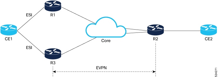
Ethernet VPN (EVPN) is a next generation solution that provide Ethernet multipoint services over MPLS networks. EVPN operates in contrast to the existing Virtual Private LAN Service (VPLS) by enabling control-plane based MAC learning in the core. In EVPN, PE's participating in the EVPN instances learn customer MAC routes in Control-Plane using MP-BGP protocol. Control-plane MAC learning brings a number of benefits that allow EVPN to address the VPLS shortcomings, including support for multi-homing with per-flow load balancing.

The EVPN control-plane MAC learning has the following benefits:

  • Eliminate flood and learn mechanism

  • Fast-reroute, resiliency, and faster reconvergence when link to dual-homed server fails

  • Enables load balancing of traffic to and from CEs that are multihomed to multiple PEs

The following EVPN modes are supported:

  • Single homing - This enables you connect a customer edge (CE) device to one provider edge (PE) device.

  • Multihoming - This enables you to connect a customer edge (CE) device to two or more provider edge (PE) devices to provide redundant connectivity. The redundant PE device ensures that there is no traffic disruption when there is a network failure. Following are the types of multihoming:

    • Single-Active - In single-active mode, only a single PE among a group of PEs attached to the particular Ethernet-Segment is allowed to forward traffic to and from that Ethernet Segment.

    • Active-Active - In active-active mode, all the PEs attached to the particular Ethernet-Segment is allowed to forward traffic to and from that Ethernet Segment.

EVPN Timers

The following table shows various EVPN timers:

Table 1. EVPN Timers

Timer

Range

Default Value

Trigger

Applicability

Action

Sequence

startup-cost-in

30-86400s

disabled

node recovered*

Single-Homed, All-Active, Single-Active

Postpone EVPN startup procedure and Hold AC link(s) down to prevent CE to PE forwarding. Startup-cost-in timer allows PE to set core protocols first.

1

recovery

20-3600s

Note


Starting from Release 6.6.3 onwards, the range is 0-3600s.

30s

node recovered, interface recovered **

Single-Homed***, Single-Active

Postpone EVPN Startup procedure. Recovery timer allows PE to set access protocols (STP) before reachability towards EVPN core is advertised.

2

peering

0-3600s

3s

node recovered, interface recovered

All-Active, Single-Active

Starts after sending EVPN RT4 to postpone rest of EVPN startup procedure. Peering timer allows remote PE (multihoming AC with same ESI) to process RT4 before DF election will happen.

3

core-de-isolation

60-300s

60s

core interface recovered

Single-Homed***, Single-Active

Postpone EVPN Startup procedure. Core-de-isolation timer allows EVPN PE nodes to relearn the MAC addresses and BGP routes received from the remote PEs.


Note


  • The timers are available in EVPN global configuration mode and in EVPN interface sub-configuration mode.

  • Startup-cost-in is available in EVPN global configuration mode only.

  • Timers are triggered in sequence (if applicable).

  • Cost-out in EVPN global configuration mode brings down AC link(s) to prepare node for reload or software upgrade.


* indicates all required software components are loaded.

** indicates link status is up.

*** you can change the recovery timer on Single-Homed AC if you do not expect any STP protocol convergence on connected CE.

EVPN Operation

At startup, PEs exchange EVPN routes in order to advertise the following:

  • VPN membership: The PE discovers all remote PE members of a given EVI. In the case of a multicast ingress replication model, this information is used to build the PE's flood list associated with an EVI.

  • Ethernet segment reachability: In multi-home scenarios, the PE auto-discovers remote PE and their corresponding redundancy mode (all-active or single-active). In case of segment failures, PEs withdraw ESI-EAD routes and retain EVI-EAD routes used at this stage in order to trigger fast convergence by signaling a MAC mass withdrawal on remote PEs.

  • Redundancy Group membership: PEs connected to the same Ethernet segment (multi-homing) automatically discover each other and elect a Designated Forwarder (DF) that is responsible for forwarding Broadcast, Unknown unicast and Multicast (BUM) traffic for a given EVI.

Figure 1. EVPN Operation


EVPN can operate in single homing or dual homing mode. Consider single homing scenario, when EVPN is enabled on PE, routes are advertised where each PE discovers all other member PEs for a given EVPN instance. When an unknown unicast (or BUM) MAC is received on the PE, it is advertised as EVPN type-2 routes to other PEs. MAC routes are advertised to the other PEs using EVPN type-2 routes. In multi-homing scenarios Type 1, 3 and 4 are advertised to discover other PEs and their redundancy modes (single active or active-active). Use of Type-1 route is to auto-discover other PE which hosts the same CE. The other use of this route type is to fast route unicast traffic away from a broken link between CE and PE. Type-4 route is used for electing designated forwarder. For instance, consider the topology when customer traffic arrives at the PE, EVPN MAC advertisement routes distribute reachability information over the core for each customer MAC address learned on local Ethernet segments. Each EVPN MAC route announces the customer MAC address and the Ethernet segment associated with the port where the MAC was learned from and is associated MPLS label. This EVPN MPLS label is used later by remote PEs when sending traffic destined to the advertised MAC address.

Behavior Change due to ESI Label Assignment

To adhere to RFC 7432 recommendations, the encoding or decoding of MPLS label is modified for extended community. Earlier, the lower 20 bits of extended community were used to encode the split-horizon group (SHG) label. Now, the SHG label encoding uses from higher 20 bits of extended community.

According to this change, routers in same ethernet-segment running old and new software release versions decodes extended community differently. This change causes inconsistent SHG labels on peering EVPN PE routers. Almost always, the router drops BUM packets with incorrect SHG label. However, in certain conditions, it may cause remote PE to accept such packets and forward to CE potentially causing a loop. One such instance is when label incorrectly read as NULL.

To overcome this problem, Cisco recommends you to:

  • Minimize the time both PEs are running different software release versions.

  • Before upgrading to a new release, isolate the upgraded node and shutdown the corresponding AC bundle.

  • After upgrading both the PEs to the same release, you can bring both into service.

Similar recommendations are applicable to peering PEs with different vendors with SHG label assignment that does not adhere to RFC 7432.

EVPN Route Types

The EVPN network layer reachability information (NLRI) provides different route types.

Table 2. EVPN Route Types

Route Type

Name

Usage

1

Ethernet Auto-Discovery (AD) Route

Few routes sent per ES, carry the list of EVIs that belong to ES

2

MAC/IP Advertisement Route

Advertise MAC, address reachability, advertise IP/MAC binding

3

Inclusive Multicast Ethernet Tag Route

Multicast Tunnel End point discovery

4

Ethernet Segment Route

Redundancy group discovery, DF election

Route Type 1: Ethernet Auto-Discovery (AD) Route

The Ethernet (AD) routes are advertised on per EVI and per ESI basis. These routes are sent per ES. They carry the list of EVIs that belong to the ES. The ESI field is set to zero when a CE is single-homed.

Route Type 2: MAC/IP Advertisement Route

The host's IP and MAC addresses are advertised to the peers within NRLI. The control plane learning of MAC addresses reduces unknown unicast flooding.

Route Type 3: Inclusive Multicast Ethernet Tag Route

This route establishes the connection for broadcast, unknown unicast, and multicast (BUM) traffic from a source PE to a remote PE. This route is advertised on per VLAN and per ESI basis.

Route Type 4: Ethernet Segment Route

Ethernet segment routes enable to connect a CE device to two or PE devices. ES route enables the discovery of connected PE devices that are connected to the same Ethernet segment.

Configure EVPN L2 Bridging Service

Perform the following steps to configure EVPN L2 bridging service.

SUMMARY STEPS

  1. configure
  2. l2vpn
  3. bridge group bridge-group-name
  4. bridge-domain bridge-domain-name
  5. interface GigabitEthernet GigabitEthernet Interface Instance
  6. evi ethernet vpn id
  7. exit
  8. exit
  9. bridge-domain bridge-domain-name
  10. interface GigabitEthernet GigabitEthernet Interface Instance
  11. evi ethernet vpn id
  12. Use the commit or end command.

DETAILED STEPS


Step 1

configure

Example:

RP/0/RSP0/CPU0:router# configure

Enters the global configuration mode.

Step 2

l2vpn

Example:

RP/0/RSP0/CPU0:router(config)# l2vpn

Enters the l2vpn configuration mode.

Step 3

bridge group bridge-group-name

Example:

RP/0/RSP0/CPU0:router(config-l2vpn)# bridge group 1 

Enters the bridge group configuration mode.

Step 4

bridge-domain bridge-domain-name

Example:

RP/0/RSP0/CPU0:router(config-l2vpn-bg)# bridge-domain 1-1 

Enters the bridge domain configuration mode.

Step 5

interface GigabitEthernet GigabitEthernet Interface Instance

Example:


RP/0/RSP0/CPU0:router(config-l2vpn-bg-bd)# interface GigabitEthernet 0/0/0/1.1

Enters interface configuration mode.

Step 6

evi ethernet vpn id

Example:

RP/0/RSP0/CPU0:router(config-l2vpn-bg-bd-ac)# evi 1

Creates the ethernet VPN ID.

Step 7

exit

Example:

RP/0/RSP0/CPU0:router(config-l2vpn-bg-bd-ac-evi)# exit

Exits the current configuration mode.

Step 8

exit

Example:

RP/0/RSP0/CPU0:router(config-l2vpn-bg-bd)# exit

Exits the current configuration mode.

Step 9

bridge-domain bridge-domain-name

Example:

RP/0/RSP0/CPU0:router(config-l2vpn-bg)# bridge-domain 1-2 

Enters the bridge domain configuration mode.

Step 10

interface GigabitEthernet GigabitEthernet Interface Instance

Example:


RP/0/RSP0/CPU0:router(config-evpn)# interface GigabitEthernet 0/0/0/1.2

Enters interface configuration mode.

Step 11

evi ethernet vpn id

Example:

RP/0/RSP0/CPU0:router(config-l2vpn-bg-bd-ac)# evi 2

Creates the ethernet VPN ID.

Step 12

Use the commit or end command.

commit - Saves the configuration changes and remains within the configuration session.

end - Prompts user to take one of these actions:

  • Yes - Saves configuration changes and exits the configuration session.

  • No - Exits the configuration session without committing the configuration changes.

  • Cancel - Remains in the configuration mode, without committing the configuration changes.


EVPN Software MAC Learning

MAC learning is the method of learning the MAC addresses of all devices available in a VLAN.

The MAC addresses learned on one device needs to be learned or distributed on the other devices in a VLAN. EVPN Native with software MAC Learning feature enables the distribution of the MAC addresses learned on one device to the other devices connected to a network. The MAC addresses are learnt from the remote devices using BGP.

Figure 2. EVPN Native with Software MAC Learning

The above figure illustrates the process of Software MAC Learning. The following are the steps involved in the process:

  1. Traffic comes in on one port in the bridge domain.

  2. The source MAC address (AA) is learnt on DCI1 and is stored as a dynamic MAC entry.

  3. The MAC address (AA) is converted into a type-2 BGP route and is sent over BGP to all the remote PEs in the same EVI.

  4. The MAC address (AA) is updated on DCI3 as a static remote MAC address.

Software and Hardware Support

The EVPN Native with Software MAC Learning feature is supported on Cisco ASR 9000 Series Routers that support Cisco IOS XR and Cisco IOS XR 64-bit software.

Configure EVPN Native with Software MAC Learning

The following section describes how you can configure EVPN Native with Software MAC Learning:


/* Configure bridge domain. */

RP/0/RSP0/CPU0:router(config)# l2vpn
RP/0/RSP0/CPU0:router(config-l2vpn)# bridge group EVPN_SH
RP/0/RSP0/CPU0:router(config-l2vpn-bg)# bridge-domain EVPN_2001
RP/0/RSP0/CPU0:router(config-l2vpn-bg-bd)# interface TenGigE0/4/0/10.2001
RP/0/RSP0/CPU0:router(config-l2vpn-bg-bd)# interface BundleEther 20.2001
RP/0/RSP0/CPU0:router(config-l2vpn-bg-bd)# storm-control broadcast pps 10000
RP/0/RSP0/CPU0:router(config-l2vpn-bg-bd)# neighbor 20.20.20.20 pw-id 1020001
RP/0/RSP0/CPU0:router(config-l2vpn-bg-bd-nbr)# evi 2001
RP/0/RSP0/CPU0:router(config-l2vpn-bg-bd)# exit
RP/0/RSP0/CPU0:router(config-l2vpn-bg)# exit
RP/0/RSP0/CPU0:router(config-l2vpn)# exit
/* Configure advertisement of MAC routes, suppress unknown unicast, disable the control word,*/
/* configure the flow label, configure BGP route-exchange using RT. */

RP/0/RSP0/CPU0:router(config)# evpn
RP/0/RSP0/CPU0:router(config-evpn)# evi 2001
/* Use the advertise-mac command to control the advertisement of MAC routes through BGP to other neighbors. */
RP/0/RSP0/CPU0:router(config-evpn-evi)# advertise-mac
/* Use the unknown-unicast-suppress command to prevent the flooding of unknown unicast traffic received from the EVPN core towards all other EVPN bridge-ports. */
RP/0/RSP0/CPU0:router(config-evpn-evi)# unknown-unicast-suppress
/* Use the control-word-disable command to prevent the control word from being sent */
/* in the packet that is sent to MPLS core. The control word functionality is enabled by default. */
RP/0/RSP0/CPU0:router(config-evpn-evi)# control-word-disable
/* Use the load-balance flow label static command to add additional flow label header to the packet */
/* that is sent to MPLS core. The loadbalance flow functionality is disabled by default. */
RP/0/RSP0/CPU0:router(config-evpn-evi)# load-balance flow label static
/* Perform the following steps to configure BGP route-exchange using RT */ 
RP/0/RSP0/CPU0:router(config-evpn-evi)# bgp
RP/0/RSP0/CPU0:router(config-evpn-evi)# route-target import 200:101
RP/0/RSP0/CPU0:router(config-evpn-evi)# route-target export 200:101
/* Configure address family session in BGP. */

RP/0/RSP0/CPU0:router# configure
RP/0/RSP0/CPU0:router(config)# router bgp 200
RP/0/RSP0/CPU0:router(config-bgp)# bgp router-id 40.40.40.40
RP/0/RSP0/CPU0:router(config-bgp)# address-family l2vpn evpn
RP/0/RSP0/CPU0:router(config-bgp)# neighbor 10.10.10.10
RP/0/RSP0/CPU0:router(config-bgp-nbr)# remote-as 200
RP/0/RSP0/CPU0:router(config-bgp-nbr)# description MPLSFACINGPEER
RP/0/RSP0/CPU0:router(config-bgp-nbr)# update-source Loopback 0
RP/0/RSP0/CPU0:router(config-bgp-nbr)# address-family l2vpn evpn

Supported Modes for EVPN Native with Software MAC Learning

The following are the modes in which EVPN MAC Learning is supported:

  • Single Home Device or Single Home Network

  • Dual Home Device (DHD) - All Active Load Balancing

  • Dual Home Device - Single-Active Load Balancing

Single Home Device or Single Home Network

The following section describes how you can configure EVPN Native with Software MAC Learning feature in single home device or single home network:

Figure 3. Single Home Device or Single Home Network (SHD/SHN)

In the above figure, the PE (PE1) is attached to Ethernet Segment using bundle or physical interfaces. Null Ethernet Segment Identifier (ESI) is used for SHD/SHN.

Configure EVPN in Single Home Device or Single Home Network

/* Configure bridge domain. */

RP/0/RSP0/CPU0:router(config)# l2vpn
RP/0/RSP0/CPU0:router(config-l2vpn)# bridge group EVPN_ALL_ACTIVE 
RP/0/RSP0/CPU0:router(config-l2vpn-bg)# bridge-domain EVPN_2001
RP/0/RSP0/CPU0:router(config-l2vpn-bg-bd)# interface BundleEther1.2001
RP/0/RSP0/CPU0:router(config-l2vpn-bg-bd)# evi 2001
/* Configure advertisement of MAC routes. */

RP/0/RSP0/CPU0:router(config)# evpn
RP/0/RSP0/CPU0:router(config-evpn)# evi 2001
RP/0/RSP0/CPU0:router(config-evpn-evi)# advertise-mac
/* Configure address family session in BGP. */

RP/0/RSP0/CPU0:router# configure
RP/0/RSP0/CPU0:router#(config)# router bgp 200
RP/0/RSP0/CPU0:router#(config-bgp)# bgp router-id 40.40.40.40
RP/0/RSP0/CPU0:router#(config-bgp)# address-family l2vpn evpn
RP/0/RSP0/CPU0:router#(config-bgp)# neighbor 10.10.10.10
RP/0/RSP0/CPU0:router#(config-bgp-nbr)# remote-as 200
RP/0/RSP0/CPU0:router#(config-bgp-nbr)# description MPLSFACING-PEER
RP/0/RSP0/CPU0:router#(config-bgp-nbr)# update-source Loopback 0
RP/0/RSP0/CPU0:router#(config-bgp-nbr)# address-family l2vpn evpn
Running Configuration

l2vpn 
bridge group EVPN_ALL_ACTIVE 
 bridge-domain EVPN_2001 
  interface BundleEther1.2001
  evi 2001 
!
evpn
 evi 2001  
  advertise-mac
! 
router bgp 200 bgp 
 router-id 40.40.40.40
 address-family l2vpn evpn
 neighbor 10.10.10.10 
  remote-as 200 description MPLS-FACING-PEER 
  updatesource Loopback0 
  addressfamily l2vpn evpn 

Verification

Verify EVPN in single home devices.


RP/0/RSP0/CPU0:router# show evpn ethernet-segment interface Te0/4/0/10 detail

Ethernet Segment Id    Interface   Nexthops
--------------------   ----------  ----------
N/A     													  Te0/4/0/10  20.20.20.20
……………
 Topology :
 Operational : SH
 Configured : Single-active (AApS) (default) 

Dual Home Device—All-Active Load Balancing Mode

The following section describes how you can configure EVPN Software MAC Learning feature in dual home device (DHD) in all-active load balancing mode:

Figure 4. Dual Home Device —All-Active Load Balancing Mode

All-active load-balancing is known as Active/Active per Flow (AApF). In the above figure, identical Ethernet Segment Identifier is used on both EVPN PEs. PEs are attached to Ethernet Segment using bundle interfaces. In the CE, single bundles are configured towards two EVPN PEs. In this mode, the MAC address that is learnt is stored on both PE1 and PE2. Both PE1 and PE2 can forward the traffic within the same EVI.

Configure EVPN Software MAC Learning in Dual Home Device—All-Active Mode

This section describes how you can configure EVPN Software MAC Learning feature in dual home device—all-active mode:

/* Configure bridge domain. */

RP/0/RSP0/CPU0:router(config)# l2vpn
RP/0/RSP0/CPU0:router(config-l2vpn)# bridge group EVPN_ALL_ACTIVE 
RP/0/RSP0/CPU0:router(config-l2vpn-bg)# bridge-domain EVPN_2001
RP/0/RSP0/CPU0:router(config-l2vpn-bg-bd)# interface Bundle-Ether1
RP/0/RSP0/CPU0:router(config-l2vpn-bg-bd)# evi 2001

/* Configure advertisement of MAC routes. */

RP/0/RSP0/CPU0:router(config)# evpn
RP/0/RSP0/CPU0:router(config-evpn)# evi 2001
RP/0/RSP0/CPU0:router(config-evpn-evi)# advertise-mac
RP/0/RSP0/CPU0:router(config-evpn-evi)# exit
RP/0/RSP0/CPU0:router(config-evpn)# interface Bundle-Ether1
RP/0/RSP0/CPU0:router(config-evpn-ac)# ethernet-segment
RP/0/RSP0/CPU0:router(config-evpn-ac-es)# identifier type 0 01.11.00.00.00.00.00.00.01

/* Configure address family session in BGP. */

RP/0/RSP0/CPU0:router# configure
RP/0/RSP0/CPU0:router#(config)# router bgp 200
RP/0/RSP0/CPU0:router#(config-bgp)# bgp router-id 209.165.200.227
RP/0/RSP0/CPU0:router#(config-bgp)# address-family l2vpn evpn
RP/0/RSP0/CPU0:router#(config-bgp)# neighbor 10.10.10.10
RP/0/RSP0/CPU0:router#(config-bgp-nbr)# remote-as 200
RP/0/RSP0/CPU0:router#(config-bgp-nbr)# description MPLS-FACING-PEER
RP/0/RSP0/CPU0:router#(config-bgp-nbr)# update-source Loopback 0
RP/0/RSP0/CPU0:router#(config-bgp-nbr)# address-family l2vpn evpn

/* Configure Link Aggregation Control Protocol (LACP) bundle. */

RP/0/RSP0/CPU0:router# configure
RP/0/RSP0/CPU0:router(config)# interface Bundle-Ether1
RP/0/RSP0/CPU0:router(config-if)# lacp switchover suppress-flaps 300
RP/0/RSP0/CPU0:router(config-if)# exit

/* Configure VLAN Header Rewrite.*/

RP/0/RSP0/CPU0:router# configure
RP/0/RSP0/CPU0:router(config)# interface Bundle-Ether1 l2transport
RP/0/RSP0/CPU0:router(config-if)# encapsulation dot1q 10
RP/0/RSP0/CPU0:router(config-if)# rewrite ingress tag pop 1 symmetric


Note


Configure the same mlacp system priority <id> for both the dual homed PE routers to enable all-active load balancing.


Running Configuration

l2vpn
bridge group EVPN_ALL_ACTIVE
 bridge-domain EVPN_2001
 interface Bundle-Ether1
 !
 evi 2001
 !
!
evpn
 evi 2001
 !
 advertise-mac
 !
 interface Bundle-Ether1
  ethernet-segment
  identifier type 0 01.11.00.00.00.00.00.00.01
  !
 !
router bgp 200
bgp router-id  209.165.200.227
address-family l2vpn evpn
!
neighbor 10.10.10.10
 remote-as 200
 description MPLS-FACING-PEER
 update-source Loopback0
 address-family l2vpn evpn
!
interface Bundle-Ether1
lacp switchover suppress-flaps 300
load-interval 30
!
interface Bundle-Ether1 l2transport
 encapsulation dot1aq 2001
 rewrite ingress tag pop 1 symmetric
!

Verification

Verify EVPN in dual home devices in All-Active mode.


Note


With the EVPN IRB, the supported label mode is per-VRF.

RP/0/RSP0/CPU0:router# show evpn ethernet-segment interface Bundle-Ether 1 carvin$

Ethernet Segment Id        Interface  Nexthops
-------- ---------- 	      --------   --------
0100.211b.fce5.df00.0b00   BE1       10.10.10.10
 209.165.201.1
Topology :
 Operational : MHN
 Configured : All-active (AApF) (default)
 Primary Services : Auto-selection
 Secondary Services: Auto-selection
 Service Carving Results:
 Forwarders : 4003
 Elected : 2002
 EVI E : 2000, 2002, 36002, 36004, 36006, 36008
 ........
 Not Elected : 2001
 EVI NE : 2001, 36001, 36003, 36005, 36007, 36009

	MAC Flushing mode : Invalid

Peering timer : 3 sec [not running]
 Recovery timer : 30 sec [not running]
 Local SHG label : 34251
 Remote SHG labels : 1
  38216 : nexthop 209.165.201.1

Dual Home Device—Single-Active Load Balancing

The following section describes how you can configure EVPN Native with Software MAC Learning feature in dual home device in single-active load balancing mode:

Figure 5. Dual Home Device (DHD)—Single-Active Load Balancing

Single-active load balancing also is known as Active/Active per Service (AApS).

Identical ESI are configured on both EVPN PEs. In the CE, separate bundles or independent physical interfaces are configured towards two EVPN PEs. In this mode, the MAC address that is learnt is stored on both PE1 and PE2. Only one PE can forward traffic within the EVI at a given time.

Configure EVPN in Dual Home Device—Single-Active Mode

/* Configure bridge domain. */

RP/0/RSP0/CPU0:router(config)# l2vpn
RP/0/RSP0/CPU0:router(config-l2vpn)# bridge group EVPN_ALL_ACTIVE 
RP/0/RSP0/CPU0:router(config-l2vpn-bg)# bridge-domain EVPN_2001
RP/0/RSP0/CPU0:router(config-l2vpn-bg-bd)# interface Bundle-Ether1
RP/0/RSP0/CPU0:router(config-l2vpn-bg-bd)# evi 2001

/* Configure VLAN Header Rewrite (Single-tagged sub-interface).*/

RP/0/RSP0/CPU0:router# configure
RP/0/RSP0/CPU0:router(config)# interface Bundle-Ether1 l2transport
RP/0/RSP0/CPU0:router(config-if)# lacp switchover suppress-flaps 300
RP/0/RSP0/CPU0:router(config-if)# exit
RP/0/RSP0/CPU0:router(config)# interface Bundle-Ether1 l2transport
RP/0/RSP0/CPU0:router(config-if)# encapsulation dot1q 10
RP/0/RSP0/CPU0:router(config-if)# rewrite ingress tag pop 1 symmetric

/* Configure advertisement of MAC routes. */

RP/0/RSP0/CPU0:router(config)# evpn
RP/0/RSP0/CPU0:router(config-evpn)# evi 2001
RP/0/RSP0/CPU0:router(config-evpn-evi)# advertise-mac

/* Configure load balancing. */

RP/0/RSP0/CPU0:router(config)# evpn
RP/0/RSP0/CPU0:router(config-evpn)# evi 2001
RP/0/RSP0/CPU0:router(config-evpn-evi)# advertise-mac
RP/0/RSP0/CPU0:router(config-evpn-evi)# exit
RP/0/RSP0/CPU0:router(config-evpn)# interface Bundle-Ether1
RP/0/RSP0/CPU0:router(config-evpn-ac)# ethernet-segment
RP/0/RSP0/CPU0:router(config-evpn-ac-es)# load-balancing-mode single-active
RP/0/RSP0/CPU0:router(config-evpn-ac-es)# identifier type 0 12.12.00.00.00.00.00.00.02
RP/0/RSP0/CPU0:router(config-evpn-ac-es)# bgp route-target 1212.0000.0002

/* Configure address family session in BGP. */

RP/0/RSP0/CPU0:router# configure
RP/0/RSP0/CPU0:router#(config)# router bgp 200
RP/0/RSP0/CPU0:router#(config-bgp)# bgp router-id 40.40.40.40
RP/0/RSP0/CPU0:router#(config-bgp)# address-family l2vpn evpn
RP/0/RSP0/CPU0:router#(config-bgp)# neighbor 10.10.10.10
RP/0/RSP0/CPU0:router#(config-bgp-nbr)# remote-as 200
RP/0/RSP0/CPU0:router#(config-bgp-nbr)# description MPLSFACING-PEER
RP/0/RSP0/CPU0:router#(config-bgp-nbr)# update-source Loopback 0
RP/0/RSP0/CPU0:router#(config-bgp-nbr)# address-family l2vpn evpn

Verification

Verify EVPN in dual home devices in Single-Active mode.


RP/0/RSP0/CPU0:router# show evpn ethernet-segment int Bundle-Ether 1 carving detail

...
Ethernet Segment Id       Interface          Nexthops 
----- ------------------  ----------         ----------- 
0012.1200.0000.0000.0002  BE1 		            10.10.10.10  30.30.30.30
 
ESI type : 0
 Value : 12.1200.0000.0000.0002
 ES Import RT : 1212.0000.0000 (from ESI) 

Source MAC : 0000.0000.0000 (N/A)
Topology :
 Operational : MHN
 Configured : Single-active (AApS)
 Primary Services : Auto-selection
 Secondary Services: Auto-selection
 
 Service Carving Results:
 Forwarders : 2
 Elected : 1
 EVI E : 500, 2001
 Not Elected : 1
 EVI NE : 501

Verify EVPN Native with Software MAC Learning

Verify the packet drop statistics.

RP/0/RSP0/CPU0:router# show l2vpn bridge-domain bd-name EVPN_2001 details

Bridge group: EVPN_ALL_ACTIVE, bridge-domain: EVPN_2001, id: 1110,
state: up, ShgId: 0, MSTi: 0
 List of EVPNs:
 EVPN, state: up
 evi: 2001
 XC ID 0x80000458
 Statistics:
 packets: received 28907734874 (unicast 9697466652), sent
76882059953
 bytes: received 5550285095808 (unicast 1861913597184), sent
14799781851396
 MAC move: 0
 List of ACs:
 AC: TenGigE0/4/0/10.2001, state is up
 Type VLAN; Num Ranges: 1
...
 Statistics:
 packets: received 0 (multicast 0, broadcast 0, unknown
unicast 0, unicast 0), sent 45573594908
 bytes: received 0 (multicast 0, broadcast 0, unknown unicast
0, unicast 0), sent 8750130222336
 MAC move: 0
 ........

Verify the EVPN EVI information with the VPN-ID and MAC address filter.


RP/0/RSP0/CPU0:router# show evpn evi vpn-id 2001 neighbor

Neighbor IP    vpn-id
-----------   --------
20.20.20.20   2001
30.30.30.30   2001

Verify the BGP L2VPN EVPN summary.


RP/0/RSP0/CPU0:router# show bgp l2vpn evpn summary
...
Neighbor    Spk   AS     MsgRcvd MsgSent  TblVer    InQ  OutQ  Up/Down  St/PfxRcd
20.20.20.20 0    200     216739  229871   200781341  0    0     3d00h   348032
30.30.30.30 0    200     6462962 4208831  200781341  10   0     2d22h   35750

Verify the MAC updates to the L2FIB table in a line card.


RP/0/RSP0/CPU0:router# show l2vpn mac mac all location 0/6/CPU0

Topo ID Producer Next Hop(s)     Mac Address    IP Address
------- -------- -----------     -------------- ----------
1112    0/6/CPU0 Te0/6/0/1.36001 00a3.0001.0001

Verify the MAC updates to the L2FIB table in a route switch processor (RSP).


RP/0/RSP0/CPU0:router# show l2vpn mac mac all location 0/RSP0/CPU0

Topo ID  Producer     Next Hop(s)     Mac Address    IP Address
-------  --------    -----------     -------------- ----------
1112     0/RSP0/CPU0 Te0/6/0/1.36001 00a3.0001.0001

Verify the summary information for the MAC address.


RP/0/RSP0/CPU0:router# show l2vpn forwarding bridge-domain EVPN_ALL_ACTIVE:EVPN_2001 mac-address location 0/6/CPU0

.....
Mac Address     Type      Learned from/Filtered on   LC learned   Resync Age/Last Change
Mapped to
0000.2001.5555  dynamic   Te0/0/0/2/0.2001           N/A          11 Jan 14:37:22
N/A <-- local dynamic
00bb.2001.0001 dynamic    Te0/0/0/2/0.2001           N/A          11 Jan 14:37:22
N/A
0000.2001.1111 EVPN       BD id: 1110                N/A 									N/A
N/A <-- remote static
00a9.2002.0001 EVPN 						BD id: 1110 															N/A 									N/A
N/A

Verify the EVPN EVI information with the VPN-ID and MAC address filter.


RP/0/RSP0/CPU0:router# show evpn evi vpn-id 2001 mac

EVI 			MAC address 			 IP address 							Nexthop 					Label
---- 		------------- 	 -----------       -------      ------
2001 		00a9.2002.0001  :: 															10.10.10.10  34226      <-- Remote MAC
2001 		00a9.2002.0001  :: 															30.30.30.30  34202

2001 		0000.2001.5555  20.1.5.55 			     TenGigE0/0/0/2/0.2001 34203    <-- local MAC


RP/0/RSP0/CPU0:router# RP/0/RSP0/CPU0:router# show evpn evi vpn-id 2001 mac 00a9.2002.0001 detail

EVI     MAC address      IP address  Nexthop      Label
----    --------------   ----------  -------      ----- 
2001    00a9.2002.0001   ::          10.10.10.10  34226

2001    00a9.2002.0001   ::          30.30.30.30  34202

 Ethernet Tag : 0
 Multi-paths Resolved : True <--- aliasing to two remote PE with All-Active load balancing

 Static : No
 Local Ethernet Segment : N/A
 Remote Ethernet Segment : 0100.211b.fce5.df00.0b00
 Local Sequence Number : N/A
 Remote Sequence Number : 0
 Local Encapsulation : N/A
 Remote Encapsulation : MPLS

Verify the BGP routes associated with EVPN with bridge-domain filter.


RP/0/RSP0/CPU0:router# show bgp l2vpn evpn bridge-domain EVPN_2001 route-type 2

*> [2][0][48][00bb.2001.0001][0]/104
                        0.0.0.0           0 i <------ locally learnt MAC
*>i[2][0][48][00a9.2002.00be][0]/104
  																						10.10.10.10 100 			0 i <----- remotely learnt MAC
* i 30.30.30.30 100 0 i

EVPN Software MAC Aging

You can configure MAC aging on a bridge domain to set the maximum aging time for learned MAC addresses. Decrease the aging time when you want to move the hosts to allow the bridge to adapt to the changes quickly. However, in an EVPN network, the data plane and control plane are always synchronized. Furthermore, it is desirable to have a longer aging times for:

  • MAC route stability and reliability

  • Support for very high scale of MAC routes

  • Reliable and consistent accounting without overloading the control plane

For the above-mentioned reasons, when you enable EVPN, maximum MAC aging times are not fully considered for the configured MAC aging values on the bridge domain. Also, it is observed that the aging times can be long, more than 2 hours.

Topology

Figure 6. MAC Aging in EVPN

For example, CE1 sends a frame to CE2 through router R1 and R3 using EVPN routes, and R2 receives the EVPN routes and learns CE1's MAC address from R1 and R3.

EVPN MAC Aging Process

  1. MAC Address Learning Process

    When a network device sends a frame, network device learns the MAC address and adds the MAC address to the MAC address table. For example,

    • R1 and R3 learn the MAC address of CE1 and add it to their MAC address tables.

    • R1 and R3 advertise the MAC address to the core network using EVPN routes.

    • R2 receives the EVPN routes and learns MAC address of CE1, adding it to its MAC address table.

  2. EVPN Polling Mechanism

    Every 15 minutes, the Control Plane (CP) polls the Data Plane (DP) to check if the learned MAC address is still in use. If the CP is busy, it may take up to three polling intervals approximately 45-60 minutes before it can inform the DP about the status of the MAC address.

  3. MAC Aging Process

    1. Inactive Customer Edge (CE) Device

      When a CE device stops sending frames, the DP MAC aging timer for that specific MAC address will expire after one hour. Combined with the CP polling mechanism, the effective MAC aging time is approximately two hours by default which is sum of one hour CP and one hour DP aging.

    2. Inactive MAC Address Removal

      Once the MAC aging timer expires, the inactive MAC address is removed from the MAC address table.

  4. Re-learning MAC Addresses

    If a frame from a previously aged-out MAC address is received again, the CP checks if the total MAC addresses in the table have reached 2 million.

    • If the MAC address table is full, the CP disables the MAC address learning process.

    • If the MAC address table is not full, the CP enables the MAC address learning process, and the MAC address is re-learned and added back to the table with a reset aging timer. The MAC aging cycle starts again from Step1.

EVPN Out of Service

The EVPN Out of Service feature enables you to control the state of bundle interfaces that are part of an Ethernet segment that have Link Aggregation Control protocol (LACP) configured. This feature enables you to put a node out of service (OOS) without having to manually shutdown all the bundles on their provider edge (PE).

Use the cost-out command to bring down all the bundle interfaces belonging to an Ethernet VPN (EVPN) Ethernet segment on a node. The Ethernet A-D Ethernet Segment (ES-EAD) routes are withdrawn before shutting down the bundles. The PE signals to the connected customer edge (CE) device to bring down the corresponding bundle member. This steers away traffic from this PE node without traffic disruption. The traffic that is bound for the Ethernet segment from the CE is directed to the peer PE in a multi-homing environment.

In the following topology, the CE is connected to PE1 and PE2. When you configure the cost-out command on PE1, all the bundle interfaces on the Ethernet segment are brought down. Also, the corresponding bundle member is brought down on the CE. Hence, the traffic for this Ethernet segment is now sent to PE2 from the CE.

Figure 7. EVPN Out of Service


To bring up the node into service, use no cost-out command. This brings up all the bundle interfaces belonging to EVPN Ethernet segment on the PE and the corresponding bundle members on the CE.

When the node is in cost-out state, adding a new bundle Ethernet segment brings that bundle down. Similarly, removing the bundle Ethernet segment brings that bundle up.

Use startup-cost-in command to bring up the node into service after the specified time on reload. The node will cost-out when EVPN is initialized and remain cost-out until the set time. If you execute evpn no startup-cost-in command while timer is running, the timer stops and node is cost-in.

The 'cost-out' configuration always takes precedence over the 'startup-cost-in' timer. So, if you reload with both the configurations, cost-out state is controlled by the 'cost-out' configuration and the timer is not relevant. Similarly, if you reload with the startup timer, and configure 'cost-out' while timer is running, the timer is stopped and OOS state is controlled only by the 'cost-out' configuration.

If you do a proc restart while the startup-cost-in timer is running, the node remains in cost-out state and the timer restarts.

Restrictions

  • EVPN cost-out is supported only on manually configured ESIs.

Configure EVPN Out of Service

This section describes how you can configure EVPN Out of Service.

/* Configuring node cost-out on a PE */

Router# configure
Router(config)# evpn
Router(config-evpn)# cost-out
Router(config-evpn)commit

/* Bringing up the node into service */

Router# configure
Router(config)# evpn
Router(config-evpn)# no cost-out
Router(config-evpn)commit

/* Configuring the timer to bring up the node into service after the specified time on reload */

Router# configure
Router(config)# evpn
Router(config-evpn)# startup-cost-in 6000
Router(config-evpn)commit

Running Configuration


configure
evpn
 cost-out
!

configure
evpn
 startup-cost-in 6000 
!
Verification
Verify the EVPN Out of Service configuration.

/* Verify the node cost-out configuration */

Router# show evpn summary
Fri Apr  7 07:45:22.311 IST
Global Information
-----------------------------
Number of EVIs                : 2
Number of Local EAD Entries   : 0
Number of Remote EAD Entries  : 0
Number of Local MAC Routes    : 0
Number of Local MAC Routes    : 5
          MAC                 : 5
          MAC-IPv4            : 0
          MAC-IPv6            : 0
Number of Local ES:Global MAC : 12
Number of Remote MAC Routes   : 7
          MAC                 : 7
          MAC-IPv4            : 0
          MAC-IPv6            : 0
Number of Local IMCAST Routes : 56
Number of Remote IMCAST Routes: 56
Number of Internal Labels     : 5
Number of ES Entries          : 9
Number of Neighbor Entries    : 1
EVPN Router ID                : 192.168.0.1
BGP Router ID                 : ::
BGP ASN                       : 100
PBB BSA MAC address           : 0207.1fee.be00
Global peering timer          :      3 seconds
Global recovery timer         :     30 seconds
EVPN cost-out                 : TRUE
      startup-cost-in timer   : Not configured


/* Verify the no cost-out configuration */

Router# show evpn summary
Fri Apr  7 07:45:22.311 IST
Global Information
-----------------------------
Number of EVIs                : 2
Number of Local EAD Entries   : 0
Number of Remote EAD Entries  : 0
Number of Local MAC Routes    : 0
Number of Local MAC Routes    : 5
          MAC                 : 5
          MAC-IPv4            : 0
          MAC-IPv6            : 0
Number of Local ES:Global MAC : 12
Number of Remote MAC Routes   : 7
          MAC                 : 7
          MAC-IPv4            : 0
          MAC-IPv6            : 0
Number of Local IMCAST Routes : 56
Number of Remote IMCAST Routes: 56
Number of Internal Labels     : 5
Number of ES Entries          : 9
Number of Neighbor Entries    : 1
EVPN Router ID                : 192.168.0.1
BGP Router ID                 : ::
BGP ASN                       : 100
PBB BSA MAC address           : 0207.1fee.be00
Global peering timer          :      3 seconds
Global recovery timer         :     30 seconds
EVPN cost-out                 : FALSE
      startup-cost-in timer   : Not configured


/* Verify the startup-cost-in timer configuration */

Router# show evpn summary
Fri Apr  7 07:45:22.311 IST
Global Information
-----------------------------
Number of EVIs                : 2
Number of Local EAD Entries   : 0
Number of Remote EAD Entries  : 0
Number of Local MAC Routes    : 0
Number of Local MAC Routes    : 5
          MAC                 : 5
          MAC-IPv4            : 0
          MAC-IPv6            : 0
Number of Local ES:Global MAC : 12
Number of Remote MAC Routes   : 7
          MAC                 : 7
          MAC-IPv4            : 0
          MAC-IPv6            : 0
Number of Local IMCAST Routes : 56
Number of Remote IMCAST Routes: 56
Number of Internal Labels     : 5
Number of ES Entries          : 9
Number of Neighbor Entries    : 1
EVPN Router ID                : 192.168.0.1
BGP Router ID                 : ::
BGP ASN                       : 100
PBB BSA MAC address           : 0207.1fee.be00
Global peering timer          :      3 seconds
Global recovery timer         :     30 seconds
EVPN node cost-out            : TRUE
        startup-cost-in timer : 6000

EVPN VXLAN Layer 2 Data Center Interconnect Gateway

The Cisco ASR 9000 Series Routers serve as a Data Center Interconnect (DCI) Layer 2 gateway to provide Layer 2 connectivity between EVPN VXLAN based data centers, over a MPLS-based L2VPN network. The data centers are connected through the intermediate service provider network. The EVPN VXLAN enabled data centers use EVPN control plane for distributing Layer 2 forwarding information from one data center to another data center. This feature provides redundancy, resiliency, and ease of provisioning.

The EVPN VXLAN layer 2 DCI gateway feature supports these functions:

  • VXLAN access for single homing

  • VXLAN access for all-active multi homing with anycast VXLAN Terminal EndPoint (VTEP) IP address

  • VXLAN access for all-active multi homing with unique VTEP IP address

  • EVPN ESI Multipath with VXLAN encapsulation

All-Active Multi Homing with Anycast VTEP IP Address

The DCIs use the same anycast VTEP IP address for all-active multi-homing with anycast VTEP IP address. Consider the following topology where Top of Racks (ToRs) are connected to the DCIs using multiple paths: The traffic passes from ToRs to the DCIs through multiple physical paths and uses anycast IP address for load balancing. DCI1 and DCI2 advertise MAC routes to ToRs using the same anycast IP address as that of the next-hop. So, the ToR sends the traffic to the same anycast IP address of the DCIs, and uses IGP ECMP for load balancing. A virtual PortChannel (vPC) allows ToR1 and ToR2 to have the same IP configuration. ToR1 and ToR2 advertise MAC routes to DCIs using the same IP address as that of the next-hop. So, the DCI sends the traffic to the same IP address of the ToRs, and uses IGP ECMP for load balancing. The DCI sends the traffic to the remote data center through MPLS forwarding.

Figure 8. All-Active Multi Homing with Anycast VTEP IP Address


All-Active Multi Homing with Unique VTEP IP Address

The DCIs do not share anycast VTEP IP address for all-active multi homing with unique VTEP IP address. Each DCI uses a unique VTEP IP address. Consider the following topology where ToR receives the MAC routes from DCIs. Each MAC route has a unique next-hop. Because both DCI1 and DCI2 advertise routes for the same MAC with different next-hops, ToR has two equal cost next-hops for the same MAC. When ToR sends the traffic to the MAC, ToR load balances the traffic on both next-hops.

Figure 9. All-Active Multi Homing with Unique VTEP IP Address


EVPN ESI Multipath for VxLAN - EVI Based Load balancing

The EVPN Ethernet Segment Identifier (ESI) Multipath feature supports multi-path traffic to active-active dual-homed TORs and DCIs to provide redundant connectivity within the data center. ESI multi paths are discovered by the ASR9k DCI router through EVPN signalling. The path selection is based on Ethernet Segment Identifier (ESI) and EVPN instance (EVI). To resolve paths for MAC routes received, use Ethernet A-D routes per ES ( ES-EAD) and Ethernet A-D routes per EVI (EVI-EAD) as specified in RFC 7432.

Consider the following topology where DCIs receive the MAC routes from ToRs and each MAC route has a next-hop for each ToR. Similarly, DCIs advertise MAC routes with different next-hops to ToRs. When DCI sends the traffic to VM, which is behind a pair of ToRs, there are two paths (ToR) for every MAC. The DCI load balances the traffic on the two paths. The selection of path is based on EVI. For example, DCI1 and DCI2 selects ToR1 for all traffic destined to the MAC address learnt on EVI1; DCI1 and DCI2 selects ToR2 for all traffic destined to the MAC address learnt on EVI2.

Figure 10. EVPN ESI Multipath


EVPN ESI Multipath for VxLAN - Flow-based Load Balancing

The EVPN Ethernet Segment Identifier (ESI) Multipath for VxLAN feature supports flow-based load balancing to forward the traffic between Top of Racks (ToRs) and Data Center Interconnect (DCI), and between the source and remote DCIs. A flow is identified either by the source and destination IP address of the traffic, or the source and destination MAC address of the traffic.

In Release 6.2.1, the default load balancing mode is flow-based. You can change the load balancing mode based on per EVI. See Configure Network Virtualization Endpoint (NVE) Interface task to change the load balancing mode based on per EVI.

In Release 6.1.2, only per EVI-based load balancing was supported. Starting from Release 6.2.1, both flow-based load balancing and per EVI based load balancing are supported. The following table shows the support matrix:

Table 3. Support Matrix for EVPN ESI Multipath for VxLAN Load Balancing

Line Card

Release 6.1.2

Release 6.2.1

ASR 9000 Enhanced Ethernet Line Card

Supports only per EVI-based load balancing

Supports only per EVI-based load balancing

A9K-8x100G-LB-SE, A9K-8x100G-LB-TR, A9K-8X100GE-SE, A9K-8X100GE-TR, A9K-4X100GE-SE, A9K-4X100GE-TR, A9K-400G-DWDM-TR, A9K-MOD400-SE, A9K-MOD400-TR, A9K-MOD200-SE, A9K-MOD200-SE

Supports only per EVI-based load balancing

Supports both flow-based and per EVI-based load balancing

The unknown unicast flooding on traffic received from VxLAN segment is supported. In Release 6.2.1, by default, the unknown unicast flooding on traffic received from VxLAN segment is enabled. To disable the unknown unicast flooding, use the suppress-unknown-unicast-flooding command. See Configure Network Virtualization Endpoint (NVE) Interface task to disable unknown unicast flooding on traffic received from VxLAN segment.

In Release 6.1.2, by default, the unknown unicast flooding on traffic received from VxLAN segment is disabled.

Table 4. Support Matrix for Unknown Unicast Flooding

Release

Unknown Unicast Flooding

Release 6.1.2 The unknown unicast flooding on traffic received from VxLAN segment is disabled.
Release 6.2.1 The unknown unicast flooding on traffic received from VxLAN segment is enabled. To disable, use the suppress-unknown-unicast-flooding command.

Configure EVPN VXLAN Layer 2 Data Center Interconnect Gateway

Perform the following tasks to configure EVPN VXLAN Layer 2 Data Center Interconnect Gateway.

If you want to configure EVPN ESI Multipath feature, do not configure anycast IP address, the remaining configuration tasks remain the same.

Configure L2 EVPN Address Family under BGP Routing Process

Perform this task to enable EVPN address family under BGP routing process.

SUMMARY STEPS

  1. configure
  2. router bgp asn_id
  3. nsr
  4. bgp graceful-restart
  5. bgp router-id ip-address
  6. address-family l2vpn evpn
  7. Use the commit or end command.

DETAILED STEPS


Step 1

configure

Example:

RP/0/RSP0/CPU0:router# configure

Enters the global configuration mode.

Step 2

router bgp asn_id

Example:

RP/0/RSP0/CPU0:router(config)# router bgp 100

Specifies the BGP AS number and enters the BGP configuration mode, allowing you to configure the BGP routing process.

Step 3

nsr

Example:

RP/0/RSP0/CPU0:router(config-bgp)# nsr

Enables non-stop routing.

Step 4

bgp graceful-restart

Example:

RP/0/RSP0/CPU0:router(config-bgp)# bgp graceful-restart

Enables graceful restart on the router.

Step 5

bgp router-id ip-address

Example:

RP/0/RSP0/CPU0:router(config-bgp)# bgp router-id 209.165.200.227

Configures the router with a specified router ID.

Step 6

address-family l2vpn evpn

Example:

RP/0/RSP0/CPU0:router(config-bgp)# address-fmaily l2vpn evpn

Enables EVPN address family globally under BGP routing process and enters EVPN address family configuration submode.

Step 7

Use the commit or end command.

commit - Saves the configuration changes and remains within the configuration session.

end - Prompts user to take one of these actions:

  • Yes - Saves configuration changes and exits the configuration session.

  • No - Exits the configuration session without committing the configuration changes.

  • Cancel - Remains in the configuration mode, without committing the configuration changes.


Configure the Routing Sessions Between the DCI and ToR

Perform this task to configure the routing sessions between the DCI and ToR.

SUMMARY STEPS

  1. configure
  2. router bgp asn_id
  3. neighbor ip-address
  4. remote-as autonomous-system-number
  5. ebgp-multihop maximum hop count
  6. update-source loopback
  7. address-family l2vpn evpn
  8. import stitching-rt reoriginate
  9. route-policy route-policy-name in
  10. encapsulation-type type
  11. route-policy route-policy-name out
  12. advertise l2vpn evpn re-originated stitching-rt
  13. Use the commit or end command.

DETAILED STEPS


Step 1

configure

Example:

RP/0/RSP0/CPU0:router# configure

Enters the global configuration mode.

Step 2

router bgp asn_id

Example:

RP/0/RSP0/CPU0:router(config)# router bgp 100

Specifies the BGP AS number and enters the BGP configuration mode, allowing you to configure the BGP routing process.

Step 3

neighbor ip-address

Example:

RP/0/RSP0/CPU0:router(config-bgp)# neighbor 209.165.200.225

Places the router in neighbor configuration mode for BGP routing and configures the neighbor IP address 209.165.200.225 as a BGP peer.

Step 4

remote-as autonomous-system-number

Example:

RP/0/RSP0/CPU0:router(config-bgp-nbr)# remote-as 2000

Creates a neighbor and assigns it a remote autonomous system number.

Step 5

ebgp-multihop maximum hop count

Example:

RP/0/RSP0/CPU0:router(config-bgp-nbr)# ebgp-multihop 255

Enables multihop peerings with external BGP neighbors.

Step 6

update-source loopback

Example:

RP/0/RSP0/CPU0:router(config-bgp-nbr)# update-source loopback1

Allows BGP sessions to use the primary IP address from a particular interface as the local address.

Step 7

address-family l2vpn evpn

Example:

RP/0/RSP0/CPU0:router(config-bgp-nbr)# address-fmaily l2vpn evpn

Configures EVPN address family.

Step 8

import stitching-rt reoriginate

Example:

RP/0/RSP0/CPU0:router(config-bgp-nbr-af)# import stitching-rt reoriginate

Enables import of routing information from BGP EVPN NLRIs that has route target identifier matching the stitching route target identifier and exports this routing information after re-origination to the L2VPN BGP neighbor.

Step 9

route-policy route-policy-name in

Example:

RP/0/RSP0/CPU0:router(config-bgp-nbr-af)# route-policy pass-all in

Applies the route policy to inbound unicast routes.

Step 10

encapsulation-type type

Example:

RP/0/RSP0/CPU0:router(config-bgp-nbr-af)# encapsulation-type vxlan

Configures VXLAN as encapsulation type.

Step 11

route-policy route-policy-name out

Example:

RP/0/RSP0/CPU0:router(config-bgp-nbr-af)# route-policy pass-all out

Applies the route policy to outbound unicast routes.

Step 12

advertise l2vpn evpn re-originated stitching-rt

Example:

RP/0/RSP0/CPU0:router(config-bgp-nbr-af)# advertise l2vpn evpn re-originated stitching-rt

Configures advertisement of L2VPN EVPN routes to be received from the L2VPN BGP neighbor.

Step 13

Use the commit or end command.

commit - Saves the configuration changes and remains within the configuration session.

end - Prompts user to take one of these actions:
  • Yes - Saves configuration changes and exits the configuration session.

  • No- Exits the configuration session without committing the configuration changes.

  • Cancel - Remains in the configuration mode, without committing the configuration changes.


Configure BGP session for remote DCI Connectivity

Perform this task to configure BGP session for remote DCI connectivity.

SUMMARY STEPS

  1. configure
  2. router bgp asn_id
  3. neighbor ip-address
  4. remote-as autonomous-system-number
  5. update-source loopback
  6. address-family l2vpn evpn
  7. import re-originate stitching-rt
  8. advertise l2vpn evpn re-originated
  9. Use the commit or end command.

DETAILED STEPS


Step 1

configure

Example:

RP/0/RSP0/CPU0:router# configure

Enters the global configuration mode.

Step 2

router bgp asn_id

Example:

RP/0/RSP0/CPU0:router(config)# router bgp 200

Specifies the BGP AS number and enters the BGP configuration mode, allowing you to configure the BGP routing process.

Step 3

neighbor ip-address

Example:

RP/0/RSP0/CPU0:router(config-bgp)# neighbor 209.165.201.1

Places the router in neighbor configuration mode for BGP routing and configures the neighbor IP address 209.165.201.1 as a BGP peer.

Step 4

remote-as autonomous-system-number

Example:

RP/0/RSP0/CPU0:router(config-bgp-nbr)# remote-as 100

Creates a neighbor and assigns it a remote autonomous system number.

Step 5

update-source loopback

Example:

RP/0/RSP0/CPU0:router(config-bgp-nbr)# update-source loopback2

Allows BGP sessions to use the primary IP address from a particular interface as the local address.

Step 6

address-family l2vpn evpn

Example:

RP/0/RSP0/CPU0:router(config-bgp-nbr)# address-fmaily l2vpn evpn

Configures EVPN address family.

Step 7

import re-originate stitching-rt

Example:

RP/0/RSP0/CPU0:router(config-bgp-nbr-af)# import re-originate stitching-rt

Enables import of routing information from BGP EVPN NLRIs that have route target identifier matching the stitching route target identifier, and exports this routing information after re-origination to the L2VPN BGP neighbor.

Step 8

advertise l2vpn evpn re-originated

Example:

RP/0/RSP0/CPU0:router(config-bgp-nbr-af)# advertise l2vpn evpn re-originated

Configures the advertisement of L2VPN EVPN routes to be received from the L2VPN BGP neighbor.

Step 9

Use the commit or end command.

commit - Saves the configuration changes and remains within the configuration session.

end - Prompts user to take one of these actions:
  • Yes - Saves configuration changes and exits the configuration session.

  • No- Exits the configuration session without committing the configuration changes.

  • Cancel - Remains in the configuration mode, without committing the configuration changes.


Configure Network Virtualization Endpoint (NVE) Interface

Perform this task to create an NVE interface and configure it as a VXLAN Tunnel EndPoint (VTEP) for VxLAN.

SUMMARY STEPS

  1. configure
  2. interface nve nve-identifier
  3. source-interface loopback loopback-interface-identifier
  4. anycast source-interface loopback loopback-interface-identifier
  5. redundancy
  6. backbone vxlan
  7. iccp group group number
  8. exit
  9. backbone mpls
  10. iccp group group number
  11. exit
  12. exit
  13. member vni vni_number
  14. load-balance per-evi
  15. suppress-unknown-unicast-flooding
  16. mcast-group ip_address
  17. host-reachability protocol protocol
  18. (Optional) ingress-replication protocol protocol
  19. Use the commit or end command

DETAILED STEPS


Step 1

configure

Example:

RP/0/RSP0/CPU0:router# configure

Enters the global configuration mode.

Step 2

interface nve nve-identifier

Example:

RP/0/RSP0/CPU0:router(config)# interface nve 1

Creates the NVE interface and enters the NVE interface configuration sub-mode.

Step 3

source-interface loopback loopback-interface-identifier

Example:

RP/0/RSP0/CPU0:router(config-if)# source-interface loopback 1

Sets a loopback interface as the source interface for the VTEP.

Step 4

anycast source-interface loopback loopback-interface-identifier

Example:

RP/0/RSP0/CPU0:router(config-if)# anycast source-interface loopback 1

Configures anycast mode parameters and source interface for the anycast mode.

Anycast IP address is used for BGP next hop on the fabric side. If you want to configure the ESI multipath feature, do not configure anycast IP address.

Step 5

redundancy

Example:

RP/0/RSP0/CPU0:router(config-if)# redundancy

Configures the redundancy path.

Step 6

backbone vxlan

Example:

RP/0/RSP0/CPU0:router(config-nve-red)# backbone vxlan

Configures Inter-Chassis Communication Protocol (ICCP) VXLAN backbone.

Step 7

iccp group group number

Example:

RP/0/RSP0/CPU0:router(config-nve-red-backbone-vxlan)# iccp group 11

Configures the ICCP group number.

Step 8

exit

Example:

RP/0/RSP0/CPU0:router(config-nve-red-backbone-vxlan)# exit

Exits the backbone-vxlan submode and returns to redundancy submode.

Step 9

backbone mpls

Example:

RP/0/RSP0/CPU0:router(config-nve-red)# backbone mpls

Configures ICCP MPLS backbone.

Step 10

iccp group group number

Example:

RP/0/RSP0/CPU0:router(config-nve-red-backbone-mpls)# iccp group 12

Configures ICCP group number for MPLS backbone.

Step 11

exit

Example:

RP/0/RSP0/CPU0:router(config-nve-red-backbone-mpls)# exit

Exits the backbone-mpls submode and returns to redundancy submode.

Step 12

exit

Example:

RP/0/RSP0/CPU0:router(config-nve-red)# exit

Exits the redundancy submode and returns to interface submode.

Step 13

member vni vni_number

Example:

RP/0/RSP0/CPU0:router(config-nve)# member vni 1

Associates a single VxLAN with the NVE interface using the VxLAN Network Identifier (VNI) and specifies a multicast address associated with this VNI.

Step 14

load-balance per-evi

Example:

RP/0/RSP0/CPU0:router(config-nve-vni)# load-balance per-evi

Configures per-evi load balance mode (default is per-flow).

Step 15

suppress-unknown-unicast-flooding

Example:

RP/0/RSP0/CPU0:router(config-nve-vni)# suppress-unknown-unicast-flooding

Configures the suppression of unknown unicast flooding.

Step 16

mcast-group ip_address

Example:

RP/0/RSP0/CPU0:router(config-nve-vni)# mcast-group 209.165.202.129

Specifies a multicast address associated with the VNI.

Step 17

host-reachability protocol protocol

Example:

RP/0/RSP0/CPU0:router(config-nve-vni)# host-reachability protocol bgp

Configures the BGP control protocol for VxLAN tunnel endpoint reachability.

Step 18

(Optional) ingress-replication protocol protocol

Example:

RP/0/RSP0/CPU0:router(config-nve-vni)# ingress-replication protocol bgp

Ingress replication is supported when configured, PIM-SSM otherwise.

Step 19

Use the commit or end command

commit - Saves the configuration changes and remains within the configuration session.

end - Prompts user to take one of these actions:

  • Yes - Saves configuration changes and exits the configuration session.

  • No - Exits the configuration session without committing the configuration changes.

  • Cancel - Remains in the configuration mode, without committing the configuration changes.


Configure a Bridge Domain

Perform the following steps to configure the bridge domain on the DCI Gateway.

SUMMARY STEPS

  1. configure
  2. l2vpn
  3. bridge group bridge-group-name
  4. bridge-domain bridge-domain-name
  5. evi ethernet vpn id
  6. exit
  7. member vni vxlan-id
  8. Use the commit or end command.

DETAILED STEPS


Step 1

configure

Example:

RP/0/RSP0/CPU0:router# configure

Enters the global configuration mode.

Step 2

l2vpn

Example:

RP/0/RSP0/CPU0:router(config)# l2vpn

Enters the l2vpn configuration mode.

Step 3

bridge group bridge-group-name

Example:

RP/0/RSP0/CPU0:router(config-l2vpn)# bridge group bg1 

Enters the bridge group configuration mode.

Step 4

bridge-domain bridge-domain-name

Example:

RP/0/RSP0/CPU0:router(config-l2vpn-bg)# bridge-domain bd1 

Enters the bridge domain configuration mode.

Step 5

evi ethernet vpn id

Example:

RP/0/RSP0/CPU0:router(config-l2vpn-bg-bd)# evi 1

Creates the ethernet VPN ID.

Step 6

exit

Example:

RP/0/RSP0/CPU0:router(config-l2vpn-bg-bd-evi)# exit

Exits the EVI configuration mode and returns to bridge domain configuration mode.

Step 7

member vni vxlan-id

Example:

RP/0/RSP0/CPU0:router(config-l2vpn-bg-bd)# member vni 1

Associates a member VNI with the bridge domain.

Step 8

Use the commit or end command.

commit - Saves the configuration changes and remains within the configuration session.

end - Prompts user to take one of these actions:

  • Yes - Saves configuration changes and exits the configuration session.

  • No - Exits the configuration session without committing the configuration changes.

  • Cancel - Remains in the configuration mode, without committing the configuration changes.


Configure BGP Route Targets Import/Export Rules

By default, these parameters are auto-derived from the DCI's configuration:

  • Route Distinguisher (RD) for global Ethernet Segment table

Default: Auto-generated RD based on loopback IP address

  • EVI’s BGP Route Distinguisher (RD)

Default: Auto-generated RD based on loopback IP address

  • EVI’s BGP Route Target. Default: Auto-generated RT based on EVI ID

Perform this task to overwrite the auto-generated BGP RD/RT values and define route targets to be used for import and export of forwarding information.

SUMMARY STEPS

  1. configure
  2. evpn
  3. bgp
  4. rd { 2-byte as_number | 4-byte as_number | IP_address | none } : { nn }
  5. exit
  6. evi evi_id
  7. bgp
  8. route-target import { 2-byte as_number | 4-byte as_number | IP_address | none } : { nn }
  9. route-target export { 2-byte as_number | 4-byte as_number | IP_address | none } : { nn }
  10. exit
  11. vni vni_id stitching
  12. bgp
  13. route-target import { 2-byte as_number | 4-byte as_number | IP_address | none } : { nn }
  14. route-target export { 2-byte as_number | 4-byte as_number | IP_address | none } : { nn }
  15. Use the commit or end command.

DETAILED STEPS


Step 1

configure

Example:

RP/0/RSP0/CPU0:router# configure

Enters the global configuration mode.

Step 2

evpn

Example:

RP/0/RSP0/CPU0:router(config)# evpn

Enters EVPN configuration mode.

Step 3

bgp

Example:

RP/0/RSP0/CPU0:router(config-evpn)# bgp

Enters EVPN BGP configuration mode and configures static BGP settings for the Ethernet Segment ES:GLOBAL EVI, which is used for handling ES routes.

Step 4

rd { 2-byte as_number | 4-byte as_number | IP_address | none } : { nn }

Example:

RP/0/RSP0/CPU0:router(config-evpn-bgp)# rd 200:50

Configures the route distinguisher.

Step 5

exit

Example:

RP/0/RSP0/CPU0:router(config-evpn-bgp)# exit

Exits the current configuration mode and returns to evpn submode

Step 6

evi evi_id

Example:

RP/0/RSP0/CPU0:router(config-evpn)# evi 1

Configures Ethernet VPN ID.

The EVI ID range is from 1 to 65534.

Step 7

bgp

Example:

RP/0/RSP0/CPU0:router(config-evpn-evi)# bgp

Enters the BGP configuration mode for the specific EVI.

Step 8

route-target import { 2-byte as_number | 4-byte as_number | IP_address | none } : { nn }

Example:

RP/0/RSP0/CPU0:router(config-evpn-evi-bgp)# route-target import 101:1

Configures importing of routes from the L2 EVPN BGP NLRI that have the matching route-target value.

Step 9

route-target export { 2-byte as_number | 4-byte as_number | IP_address | none } : { nn }

Example:

RP/0/RSP0/CPU0:router(config-evpn-evi-bgp)# route-target export 101:1

Configures exporting of routes to the L2 EVPN BGP NLRIs and assigns the specified route-target identifiers to the BGP EVPN NLRIs.

Step 10

exit

Example:

RP/0/RSP0/CPU0:router(config-evpn-evi-bgp)# exit

Exits the current configuration mode and returns to evpn submode

Step 11

vni vni_id stitching

Example:

RP/0/RSP0/CPU0:router(config-evpn)# vni 1 stitching

Configures Ethernet VNI ID. Configures stitching for the VxLAN side.

The VNI ID range is from 1 to 16777215.

Step 12

bgp

Example:

RP/0/RSP0/CPU0:router(config-evpn-instance)# bgp

Enters the BGP configuration mode for the specific VNI.

Step 13

route-target import { 2-byte as_number | 4-byte as_number | IP_address | none } : { nn }

Example:

RP/0/RSP0/CPU0:router(config-evpn-instance-bgp)# route-target import 101:1

Configures importing of routes from the L2 EVPN BGP NLRI that have the matching route-target value.

Step 14

route-target export { 2-byte as_number | 4-byte as_number | IP_address | none } : { nn }

Example:

RP/0/RSP0/CPU0:router(config-evpn-instance-bgp)# route-target export 101:1

Configures exporting of routes to the L2 EVPN BGP NLRIs and assigns the specified route-target identifiers to the BGP EVPN NLRIs.

Step 15

Use the commit or end command.

commit - Saves the configuration changes and remains within the configuration session.

end - Prompts user to take one of these actions:

  • Yes - Saves configuration changes and exits the configuration session.

  • No - Exits the configuration session without committing the configuration changes.

  • Cancel - Remains in the configuration mode, without committing the configuration changes.


Configure Ethernet Segment Identifier

Perform this task to configure Ethernet Segment Identifier (ESI).

SUMMARY STEPS

  1. configure
  2. evpn
  3. interface nve nve-identifier
  4. ethernet-segment
  5. identifier type esi-type esi-identifier
  6. bgp route-target route target value
  7. Use the commit or end command

DETAILED STEPS


Step 1

configure

Example:

RP/0/RSP0/CPU0:router# configure

Enters the global configuration mode.

Step 2

evpn

Example:

RP/0/RSP0/CPU0:router# evpn

Enters EVPN configuration mode.

Step 3

interface nve nve-identifier

Example:

RP/0/RSP0/CPU0:router(config-evpn)# interface nve 1

Creates the NVE interface and enters the NVE interface configuration sub-mode

Step 4

ethernet-segment

Example:

RP/0/RSP0/CPU0:router(config-evpn-ac)# ethernet-segment

Enters the EVPN ethernet-segment configuration mode.

Step 5

identifier type esi-type esi-identifier

Example:

RP/0/RSP0/CPU0:router(config-evpn-ac-es)# identifier type 0 88.00.00.00.00.00.00.00.01

Configures Ethernet Segment Identifier .

Step 6

bgp route-target route target value

Example:

RP/0/RSP0/CPU0:router(config-evpn-ac-es)# bgp route-target 8888.0000.0001

Configures the BGP import route-target for the Ethernet-Segment.

Step 7

Use the commit or end command

commit - Saves the configuration changes and remains within the configuration session.

end - Prompts user to take one of these actions:

  • Yes - Saves configuration changes and exits the configuration session.

  • No - Exits the configuration session without committing the configuration changes.

  • Cancel - Remains in the configuration mode, without committing the configuration changes.


Configure ICCP Group

Perform this task to configure Inter Chassis Communication Protocol (ICCP) parameters.

Configure ICCP group for core interface tracking. If all interfaces are down, the DCI is isolated from the core/fabric network. The associated nve interface is brought down, and BGP NLRIs are withdrawn.

SUMMARY STEPS

  1. configure
  2. redundancy
  3. iccp group group number
  4. mode singleton
  5. backbone
  6. interface GigabitEthernet GigabitEthernet Interface Instance
  7. Use the commit or end command

DETAILED STEPS


Step 1

configure

Example:

RP/0/RSP0/CPU0:router# configure

Enters the global configuration mode.

Step 2

redundancy

Example:

RP/0/RSP0/CPU0:router(config)# redundancy

Enters redundancy configuration mode.

Step 3

iccp group group number

Example:

RP/0/RSP0/CPU0:router(config-redundancy)# iccp group 11

Configures ICCP group number.

Step 4

mode singleton

Example:

RP/0/RSP0/CPU0:router(config-redundancy-iccp-group)# mode singleton

Enables to run the group in singleton mode.

Step 5

backbone

Example:

RP/0/RSP0/CPU0:router(config-redundancy-iccp-group)# backbone

Configures ICCP backbone interface.

Step 6

interface GigabitEthernet GigabitEthernet Interface Instance

Example:

RP/0/RSP0/CPU0:router(config-redundancy-group-iccp-backbone)# interface GigabitEthernet 0/2/0/12

Configures GigabitEthernet interface.

Step 7

Use the commit or end command

commit - Saves the configuration changes and remains within the configuration session.

end - Prompts user to take one of these actions:

  • Yes - Saves configuration changes and exits the configuration session.

  • No - Exits the configuration session without committing the configuration changes.

  • Cancel - Remains in the configuration mode, without committing the configuration changes.


Enable Flow-based Load Balancing

Perform this task to enable flow-based load balancing.

SUMMARY STEPS

  1. configure
  2. l2vpn
  3. load-balancing flow {src-dst-mac | src-dst-ip}
  4. Use the commit or end command.

DETAILED STEPS


Step 1

configure

Example:

RP/0/RSP0/CPU0:router# configure

Enters the Global Configuration mode.

Step 2

l2vpn

Example:


RP/0/RSP0/CPU0:router(config)# l2vpn

Enters the L2VPN configuration mode.

Step 3

load-balancing flow {src-dst-mac | src-dst-ip}

Example:


RP/0/RSP0/CPU0:router(config-l2vpn)# load-balancing flow src-dst-ip

Enables flow-based load balancing.

Step 4

Use the commit or end command.

commit - Saves the configuration changes and remains within the configuration session.

end - Prompts user to take one of these actions:

  • Yes - Saves configuration changes and exits the configuration session.
  • No - Exits the configuration session without committing the configuration changes.
  • Cancel - Remains in the configuration mode, without committing the configuration changes.

Example: All-Active Multi Homing with Anycast VTEP IP Address Configuration

The following example shows the all-active multi homing with anycast VTEP IP address configuration:


interface nve1
source-interface loopback1
anycast source-interface loopback2 
 member vni 5100
  mcast-address 239.1.1.1
  host-reachabilty protocol bgp
!

!
evpn
 evi 10
  bgp
   route-target import 100:10
!
 vni 5100 stitching
  bgp
   route-target import 200:5100 
   route-target export 200:5100
 !
!
l2vpn
 bridge group DCI
  bridge-domain V1
   evi 10
   member vni 5100
!
router bgp 100
 bgp router-id 209.165.200.226
 address-family l2vpn evpn
 
!
 neighbor 209.165.201.2
  remote-as 100
  description core-facing
  update-source Loopback1
  address-family l2vpn evpn
   import re-originate stitching-rt
   advertise l2vpn evpn re-originated 
!
neighbor 209.165.202.130
  remote-as 200
  ebgp-multihop 255
  update-source Loopback1
  address-family l2vpn evpn
   import stitching-rt re-originate
   route-policy passall in
   encapsulation-type vxlan
   route-policy passall out
   advertise l2vpn evpn re-originated stitching-rt
!

Example: All-Active Multi Homing with Unique VTEP IP Address Configuration

The following example shows the all-active multi homing with unique VTEP IP address configuration:


interface nve1
source-interface loopback1
 member vni 5100
  mcast-address 239.1.1.1
  host-reachabilty protocol bgp
!
!
evpn
 evi 10
  bgp
   route-target import 100:10
!
 vni 5100 stitching
  bgp
   route-target import 200:5100 
   route-target export 200:5100
 !
!
l2vpn
 bridge group DCI
  bridge-domain V1
   evi 10
   member vni 5100
!
router bgp 100
 bgp router-id 209.165.200.226
 address-family l2vpn evpn
 
!
neighbor 209.165.201.2
 remote-as 100
 description core-facing
 update-source Loopback1
 address-family l2vpn evpn
   import re-originate stitching-rt
   multipath
   advertise l2vpn evpn re-originated 
!
neighbor 209.165.202.130
  remote-as 200
  ebgp-multihop 255
  update-source Loopback1
  address-family l2vpn evpn
   import stitching-rt re-originate
    multipath
     route-policy passall in
     encapsulation-type vxlan
     route-policy passall out
     advertise l2vpn evpn re-originated stitching-rt
!

EVPN Port-Active Multihoming

The EVPN Port-Active Multihoming feature supports single-active redundancy load balancing at the port-level or the interface-level. You can use this feature when you want to forward the traffic to a specific interface, rather than have a per-flow load balancing across multiple PE routers. This feature provides a faster convergence during a link failure. This feature enables protocol simplification as only one of the physical ports is active at a given time. You can enable this feature only on bundle interfaces.

EVPN port-active provides protocol simplification compared to Inter-Chassis Communication Protocol (ICCP), which runs on top of Label Distribution Protocol (LDP). You can use this feature as an alternative to multi-chassis link aggregation group (MC-LAG) with ICCP.

Also, you can use this feature when you want certain QoS features to work.

This feature allows one of the PEs to be in active mode and another in the standby mode at the port-level. Only the PE which is in the active mode sends and receives the traffic. The other PE remains in the standby mode. The PEs use the Designated Forwarder (DF) election mechanism to determine which PE must be in the active mode and which must be in the standby mode. You can use either modulo or Highest Random Weight (HRW) algorithm for per port DF election. By default, the modulo algorithm is used for per port DF election.

Figure 11. EVPN Port-Active Multihoming

Consider a topology where the customer edge device (CE) is multihomed to provider edge devices, PE1 and PE2. Use single link aggregation at the CE. Only one of the two interfaces is in the forwarding state, and the other interface is in the standby state. In this topology, PE2 is in the active mode and PE1 is in the standby mode. Hence, PE2 carries traffic from the CE. All services on the PE2 interface operate in the active mode. All services on the PE1 operate in the standby mode.

If the interface is running LACP, then the standby sets the LACP state to Out-of-Service (OOS) instead of bringing the interface state down. This state enables better convergence on standby to active transition.

If you remove the port-active configuration on both PE1 and PE2 and then add back the port-active configuration on both the PEs, PE2 is chosen as an active interface again.

EVPN port-active is compatible with the following services:

  • L2 bridging

  • L3 gateway

  • L2VPN VPLS

  • EVPN ELAN

  • EVPN IRB

  • L2VPN VPWS

  • EVPN VPWS

  • FXC


Note


MC-LAG in EVPN Multihoming is not supported and alternative EVPN port-active should be used.


This feature supports both L2 and L3 port-active functionality. L2 and L3 port-active can coexist on the same bundle. For example, if you configure port-active on a bundle, the bundle can have a mix of both L3 subinterfaces and L2 subinterfaces participating in the services mentioned above.

Configure EVPN Port-Active Multihoming

Perform this task to configure EVPN port-active multihoming.

Configure the same ESI on both the routers. Configure Ethernet-Segment in port-active load-balancing mode on peering PEs for a specific interface.

Configuration Example


/* PE1 and PE2 Configuration */

Router#configure
Router(config)#interface Bundle-Ether11
Router(config-if)#lacp system mac 3637.3637.3637
Router(config-if)#exit

Router(config)#evpn
Router(config-evpn)#interface Bundle-Ether11
Router(config-evpn-ac)#ethernet-segment
Router(config-evpn-ac-es)#identifier type 0 11.11.11.11.11.00.11.11.11
Router(config-evpn-ac-es)#load-balancing-mode port-active
Router(config-evpn-ac-es)#commit

/* If you want enable L3 port-active, configure the IP address */
Router#configure
Router(config)#interface Bundle-Ether11
Router(config-if)#ipv4 address 10.0.0.1 255.0.0.0
Router(config-if)#ipv6 address 10::1/64
Router(config-if)#commit

Running Configuration

This section shows port-active running configuration.


configure
 interface Bundle-Ether11
  lacp system mac 3637.3637.3637
 !

evpn
 interface Bundle-Ether11
  ethernet-segment
   identifier type 0 11.11.11.11.11.00.11.11.11
    load-balancing-mode port-active
   !
  !
interface Bundle-Ether11
 ipv4 address 10.0.0.1 255.0.0.0
 ipv6 address 10::1/64
 !
!

Verification

Verify that you have configured the Port-Active Multihoming feature successfully.


Router:PE2#show bundle bundle-ether 11

Bundle-Ether11
  Status:                                    Up
  Local links <active/standby/configured>:   1 / 0 / 1
  Local bandwidth <effective/available>:     1000000 (1000000) kbps
  MAC address (source):                      02b4.3cb4.a004 (Chassis pool)
  Inter-chassis link:                        No
  Minimum active links / bandwidth:          1 / 1 kbps
  Maximum active links:                      64
  Wait while timer:                          2000 ms
  Load balancing:                            
    Link order signaling:                    Not configured
    Hash type:                               Default
    Locality threshold:                      None
  LACP:                                      Operational
    Flap suppression timer:                  Off
    Cisco extensions:                        Disabled
    Non-revertive:                           Disabled
  mLACP:                                     Not configured
  IPv4 BFD:                                  Not configured
  IPv6 BFD:                                  Not configured

  Port                  Device           State        Port ID         B/W, kbps
  --------------------  ---------------  -----------  --------------
  Gi0/2/0/8             Local            Active       0x8000, 0x0006     1000000
      Link is Active

/* PE2 is in the active mode, hence the status shows as Up and the Link as Active. */

Router:PE1#show bundle bundle-ether 11

Bundle-Ether11
  Status:                                    LACP OOS  (out of service)
  Local links <active/standby/configured>:   0 / 1 / 1
  Local bandwidth <effective/available>:     0 (0) kbps
  MAC address (source):                      02cf.94c1.0a04 (Chassis pool)
  Inter-chassis link:                        No
  Minimum active links / bandwidth:          1 / 1 kbps
  Maximum active links:                      64
  Wait while timer:                          2000 ms
  Load balancing:                            
    Link order signaling:                    Not configured
    Hash type:                               Default
    Locality threshold:                      None
  LACP:                                      Operational
    Flap suppression timer:                  Off
    Cisco extensions:                        Disabled
    Non-revertive:                           Disabled
  mLACP:                                     Not configured
  IPv4 BFD:                                  Not configured
  IPv6 BFD:                                  Not configured

  Port                  Device           State        Port ID         B/W, kbps
  --------------------  ---------------  -----------  --------------
  Gi0/2/0/7             Local         Standby       0x8000, 0x0006     1000000
      Link is in standby due to bundle out of service state

/* PE1 is in the standby mode, hence the status shows as LACP OOS  (out of service) and the Link is in standby due to bundle out of service state. */ 

Router:CE#sshow bundle bundle-ether 11

Bundle-Ether11
  Status:                                    Up
  Local links <active/standby/configured>:   1 / 0 / 2
  Local bandwidth <effective/available>:     1000000 (1000000) kbps
  MAC address (source):                      02ff.566c.be04 (Chassis pool)
  Inter-chassis link:                        No
  Minimum active links / bandwidth:          1 / 1 kbps
  Maximum active links:                      64
  Wait while timer:                          2000 ms
  Load balancing:                            
    Link order signaling:                    Not configured
    Hash type:                               Default
    Locality threshold:                      None
  LACP:                                      Operational
    Flap suppression timer:                  Off
    Cisco extensions:                        Disabled
    Non-revertive:                           Disabled
  mLACP:                                     Not configured
  IPv4 BFD:                                  Not configured
  IPv6 BFD:                                  Not configured

  Port                  Device           State        Port ID         B/W, kbps
  --------------------  ---------------  -----------  -------------- 
  Gi0/0/0/8             Local            Active       0x8000, 0x0006     1000000
      Link is Active
  Gi0/0/0/16            Local            Negotiating  0x8000, 0x000b     1000000
      Partner is not Synchronized (Waiting, Standby, or LAG ID mismatch)

Router:PE2#show evpn ethernet-segment interface BE11 detail

/* The following output shows that the port-active mode is configured and the port is in the UP state. */

Ethernet Segment Id              Interface                   Nexthops
------------------------ ---------------------------------- --------------------
0011.1111.1111.0011.1111 BE11                                192.168.0.2
                                                             192.168.0.3
  ES to BGP Gates   : Ready
  ES to L2FIB Gates : Ready
  Main port         :
     Interface name : Bundle-Ether11
     Interface MAC  : 02b4.3cb4.a004
     IfHandle       : 0x00004170
     State          : Up
     Redundancy     : Not Defined
  ESI type          : 0
     Value          : 11.1111.1111.0011.1111
  ES Import RT      : 1111.1111.1100 (from ESI)
  Source MAC        : 0000.0000.0000 (N/A)
  Topology          :
     Operational    : MH
     Configured     : Port-Active
  Service Carving   : Auto-selection
     Multicast      : Disabled
  Convergence       : 
     Mobility-Flush : Count 0, Skip 0, Last n/a
  Peering Details   : 2 Nexthops
     192.168.0.2 [MOD:P:7fff]
     192.168.0.3 [MOD:P:00]
  Service Carving Results:
     Forwarders     : 0
     Elected        : 0
     Not Elected    : 0
  EVPN-VPWS Service Carving Results:
     Primary        : 0
     Backup         : 0
     Non-DF         : 0
  MAC Flushing mode : STP-TCN
  Peering timer     : 3 sec [not running]
  Recovery timer    : 20 sec [not running]
  Carving timer     : 0 sec [not running]
  Local SHG label   : None
  Remote SHG labels : 0
  Access signal mode: Bundle OOS (Default)


Router:PE1#show evpn ethernet-segment interface BE11 detail

/* The following output shows that the por-active mode is configured and the port is in the Standby state. */

Ethernet Segment Id               Interface                  Nexthops
------------------------ ---------------------------------- --------------------
0011.1111.1111.0011.1111 BE11                                192.168.0.2
                                                             192.168.0.3
  ES to BGP Gates   : Ready
  ES to L2FIB Gates : Ready
  Main port         :
     Interface name : Bundle-Ether11
     Interface MAC  : 02cf.941c.0a04
     IfHandle       : 0x00004170
     State          : Standby
     Redundancy     : Not Defined
  ESI type          : 0
     Value          : 11.1111.1111.0011.1111
  ES Import RT      : 1111.1111.1100 (from ESI)
  Source MAC        : 0000.0000.0000 (N/A)
  Topology          :
     Operational    : MH
     Configured     : Port-Active
  Service Carving   : Auto-selection
     Multicast      : Disabled
  Convergence       : 
     Mobility-Flush : Count 0, Skip 0, Last n/a
  Peering Details   : 2 Nexthops
     192.168.0.2 [MOD:P:00]
     192.168.0.3 [MOD:P:7fff]
  Service Carving Results:
     Forwarders     : 0
     Elected        : 0
     Not Elected    : 0      
  EVPN-VPWS Service Carving Results:
     Primary        : 0
     Backup         : 0
     Non-DF         : 0
  MAC Flushing mode : STP-TCN
  Peering timer     : 3 sec [not running]
  Recovery timer    : 20 sec [not running]
  Carving timer     : 0 sec [not running]
  Local SHG label   : None
  Remote SHG labels : 0
  Access signal mode: Bundle OOS (Default)

EVPN Single-Flow-Active Load Multihoming Balancing Mode

Table 5. Feature History Table

Feature Name

Release Information

Feature Description

EVPN Single-Flow-Active Multihoming Load-Balancing Mode

Release 7.3.1

This feature introduces EVPN Single-Flow-Active multihoming mode to connect PE devices in an access network that run Layer 2 access gateway protocols. In this mode, only the PE that first advertises the host MAC address in a VLAN forwards the traffic in a specific flow. When the primary link fails, the traffic quickly switches to the standby PE that learns the MAC address from the originated path, thereby providing fast convergence. A keyword, single-flow-active is added to the load-balancing-mode command.

In a ring topology, only one of the PEs, which is the active PE, sends and receives the traffic to prevent a traffic loop. When the link to the active PE fails, the traffic switches over to the standby PE. Traffic switchover takes a while because the standby PE has to learn the MAC addresses of the connected hosts. There’s a traffic loss until the traffic switch over happens.

The EVPN Single-Flow-Active multihoming mode connects PE devices in an access network, and in the event of active link failure the switchover happens immediately and reduces the traffic loss.

Both active and standby PEs learn the MAC addresses of the connected host. The PE that learns the MAC address of the host directly is called the Primary (active) PE. The primary PE advertises the learnt MAC addresses to the peer PE, which is referred as standby PE. As the standby PE learns the MAC address of the host through the active PE, this learnt path is referred to as the reoriginated path.

When the primary link fails, the convergence happens fast and the traffic is sent through the standby PE (reoriginated path).

Let us understand how EVPN single flow-active mode helps in fast convergence:

  • In this topology, the access network devices are connected through a ring topology. The access network uses Layer-2 gateway protocols such as G.8032, MPLS-TP, STP to prevent traffic loop due to continuous flooding.

  • CE1, CE2, CE3, PE1, and PE2 devices form a ring topology.

  • Host 1 is connected to CE1.

  • CE1 is connected to both PE1 and PE2, thus is multihomed.

  • PE1 and PE2 are part of the access ring.

  • Both PE1 and PE2 is configured with the same non-zero Ethernet Segment ID (ESI) number 0 36.37.00.00.00.00.00.11.00 for the bundle interface to enable multihoming of the host (CE1).

  • PE1 and PE2 belongs to te same VLAN and hence configured with the same EVPN instance (EVI) 100.

Traffic Flow

  • Consider a traffic flow from Host 1 to Host 2. The traffic is sent from Host 1 to CE1.

  • In this ring topology, the link between CE1 to CE2 is in the blocked state; the link between CE1 to CE3 is in the forwarding state. Hence, CE1 sends the traffic to PE2 through CE3.

  • PE2 first learns the MAC address of Host1 through CE1. PE2 advertises the learnt MAC address to the peering PE1.

  • As PE2 has learnt the MAC address directly from Host 1, and acts as an active PE.

  • The PE which originates the MAC route due to access learning sets the default BGP local preference attribute value to 100.

  • PE1 learns the MAC address from PE2 and acts as a stand-by PE. As PE1 gets the reoriginated MAC route from PE2, PE1 sets the BGP local preference attribute value to 80.

  • The PE that has the higher local preference always sends and receives the traffic. Thus PE1 sends the traffic to PE3. PE3 sends the traffic to Host 2.

Failure Scenario

When the link between CE1 and CE3 is down or when the link between CE3 and PE2 is down, traffic is sent through PE1.

  • When the link fails, the link CE1-CE2 changes to the forwarding state.

  • PE1 learns the MAC address of Host 1 directly and advertises the learnt MAC address to PE2.

  • PE1 sends the traffic to Host 2 through the remote PE3 with a BGP local preference value of 100.

  • PE3 sends and receives the traffic from PE1 until the access link between CE1 and CE2 changes to the blocked state.

Configuration Example

  • Configure both PE1 and PE2 with the same EVI of 100.

  • Configure both PE1 and PE2 with the same ESI 0 36.37.00.00.00.00.00.11.01.

Perform these tasks on both PE1and PE2.


/* Configure advertisement of MAC routes */
Router# configure
Router(config)# evpn
Router(config-evpn)# evi 100
Router(config-evpn-instance)# advertise-mac
Router(config-evpn-instance-mac)# root

/* Configure single-flow-active load-balancing mode */
Router(config)# evpn        
Router(config-evpn)# interface bundle-ether 1
Router(config-evpn-ac)# ethernet-segment
Router(config-evpn-ac-es)# identifier type 0 36.37.00.00.00.00.00.11.01
Router(config-evpn-ac-es)# load-balancing-mode single-flow-active
Router(config-evpn-ac-es)# root

/* Configure bridge domain and associating the evi to the bridge domain */
Router(config)# l2vpn
Router(config-l2vpn)# bridge group 100
Router(config-l2vpn-bg)# bridge-domain 100
Router(config-l2vpn-bg-bd)# interface Bundle-Ether1
Router(config-l2vpn-bg-bd-ac)# evi 100
Router(config-l2vpn-bg-bd-ac)# commit
Router(config-l2vpn-bg-bd-evi)# root
Router(config)# exit
Router#

Running Configuration


evpn      
 evi 100  
  advertise-mac
  !       
 !        
 interface Bundle-Ether1
  ethernet-segment
   identifier type 0 36.37.00.00.00.00.00.11.01
   load-balancing-mode single-flow-active
  !       
 !        
!         
l2vpn     
 bridge group 100
  bridge-domain 100
   interface Bundle-Ether1
   !      
   evi 100
   !      
  !       
 !        
!                

Verification

Verify the Ethernet Segment Status:

  • Verify that the Ethernet Segment Id is the same as that you have configured: In this example, you notice that the ESI on PE1 is 0 36.37.00.00.00.00.00.11.01.

  • Verify that the Single-flow-active mode is enabled in the Topology section.

The following example shows the output for PE1:

Router# show evpn ethernet-segment carving detail
Thu Aug  6 13:00:37.988 IST
Legend:
  B   - No Forwarders EVPN-enabled,
  C   - Backbone Source MAC missing (PBB-EVPN),
  RT  - ES-Import Route Target missing,
  E   - ESI missing,
  H   - Interface handle missing,
  I   - Name (Interface or Virtual Access) missing,
  M   - Interface in Down state,
  O   - BGP End of Download missing,
  P   - Interface already Access Protected,
  Pf  - Interface forced single-homed,
  R   - BGP RID not received,
  S   - Interface in redundancy standby state,
  X   - ESI-extracted MAC Conflict
  SHG - No local split-horizon-group label allocated

Ethernet Segment Id      Interface                          Nexthops            
------------------------ ---------------------------------- --------------------
0 36.37.00.00.00.00.00.11.01 BE1                         10.0.0.1
                                                            172.16.0.1 
  ES to BGP Gates   : Ready
  ES to L2FIB Gates : Ready
  Main port         :
     Interface name : Bundle-Ether1
     Interface MAC  : 008a.96ee.88dc
     IfHandle       : 0x20005f5c
     State          : Up
     Redundancy     : Not Defined
  ESI type          : 0
     Value          : 00.0000.0000.0000.0001
  ES Import RT      : 0000.0000.0001 (Local)
  Source MAC        : 0000.0000.0000 (N/A)
  Topology          :
     Operational    : MH, Single-flow-active
     Configured     : Single-flow-active
  Service Carving   : Auto-selection
     Multicast      : Disabled
  Convergence       : MAC-Mobility,
     Mobility-Flush : Debounce 13 sec, Count 1, Skip 1499
                    : Last 01/01 05:57:42.468
  Peering Details   : 2 Nexthops
  10.0.0.1[MOD:P:00:T]
    172.16.0.1 [MOD:P:7fff:T]
  Service Carving Synchronization:
     Mode           : NONE
     Peer Updates   :
  Service Carving Results:
     Forwarders     : 1000
     Elected        : 1000
            EVI E   :        1,       2,       3,       4,       5,       6
            EVI E   :        7,       8,       9,      10,      11,      12,
            EVI E   :       13,      14,      15,      16,      17,      18,
            EVI E   :       19,      20,      21,      22,      23,      24,
[........]
            EVI E   :      979,     980,     981,     982,     983,     984,
            EVI E   :      985,     986,     987,     988,     989,     990,
            EVI E   :      991,     992,     993,     994,     995,     996,
            EVI E   :      997,     998,     999,    1000
     Not Elected    : 0
  EVPN-VPWS Service Carving Results:
     Primary        : 0
     Backup         : 0
     Non-DF         : 0
  MAC Flushing mode : STP-TCN
  Peering timer     : 3 sec [not running]
  Recovery timer    : 30 sec [not running]
  Carving timer     : 0 sec [not running]
  Local SHG label   : 29096
  Remote SHG labels : 1
              29096 : nexthop 10.0.0.1
  Access signal mode: Bundle OOS (Default)

The following example shows the output for PE2:

Router# show evpn ethernet-segment carving detail
Thu Aug  6 13:00:37.988 IST
Legend:
  B   - No Forwarders EVPN-enabled,
  C   - Backbone Source MAC missing (PBB-EVPN),
  RT  - ES-Import Route Target missing,
  E   - ESI missing,
  H   - Interface handle missing,
  I   - Name (Interface or Virtual Access) missing,
  M   - Interface in Down state,
  O   - BGP End of Download missing,
  P   - Interface already Access Protected,
  Pf  - Interface forced single-homed,
  R   - BGP RID not received,
  S   - Interface in redundancy standby state,
  X   - ESI-extracted MAC Conflict
  SHG - No local split-horizon-group label allocated

Ethernet Segment Id      Interface                          Nexthops            
------------------------ ---------------------------------- --------------------
0 36.37.00.00.00.00.00.11.01 BE1                         10.0.0.1
                                                            172.16.0.1 
  ES to BGP Gates   : Ready
  ES to L2FIB Gates : Ready
  Main port         :
     Interface name : Bundle-Ether1
     Interface MAC  : 008a.96ee.88dc
     IfHandle       : 0x20005f5c
     State          : Up
     Redundancy     : Not Defined
  ESI type          : 0
     Value          : 00.0000.0000.0000.0001
  ES Import RT      : 0000.0000.0001 (Local)
  Source MAC        : 0000.0000.0000 (N/A)
  Topology          :
     Operational    : MH, Single-flow-active
     Configured     : Single-flow-active
  Service Carving   : Auto-selection
     Multicast      : Disabled
  Convergence       : MAC-Mobility,
     Mobility-Flush : Debounce 13 sec, Count 1, Skip 1499
                    : Last 01/01 05:57:42.468
  Peering Details   : 2 Nexthops
  10.0.0.1[MOD:P:00:T]
    172.16.0.1 [MOD:P:7fff:T]
  Service Carving Synchronization:
     Mode           : NONE
     Peer Updates   :
  Service Carving Results:
     Forwarders     : 1000
     Elected        : 1000
            EVI E   :        1,       2,       3,       4,       5,       6
            EVI E   :        7,       8,       9,      10,      11,      12,
            EVI E   :       13,      14,      15,      16,      17,      18,
            EVI E   :       19,      20,      21,      22,      23,      24,
[........]
            EVI E   :      979,     980,     981,     982,     983,     984,
            EVI E   :      985,     986,     987,     988,     989,     990,
            EVI E   :      991,     992,     993,     994,     995,     996,
            EVI E   :      997,     998,     999,    1000
     Not Elected    : 0
  EVPN-VPWS Service Carving Results:
     Primary        : 0
     Backup         : 0
     Non-DF         : 0
  MAC Flushing mode : STP-TCN
  Peering timer     : 3 sec [not running]
  Recovery timer    : 30 sec [not running]
  Carving timer     : 0 sec [not running]
  Local SHG label   : 29098
  Remote SHG labels : 1
              29098 : nexthop 172.16.0.1
  Access signal mode: Bundle OOS (Default)

Associated Commands

  • load-balancing-mode

  • show evpn ethernet-segment

EVPN Convergence Using NTP Synchronization

Table 6. Feature History Table

Feature Name

Release Information

Feature Description

EVPN Convergence Using NTP Synchronization

Release 7.3.1

This feature leverages the NTP clock synchronization mechanism to handle the transfer of DF role from one edge device to another. In this mechanism, the newly added or recovered PE advertises the Service Carving Timestamp along with the current time to peering PEs. This improves convergence by reducing the time for DF election from three seconds to a few tens of milliseconds. The show evpn ethernet-segment  command is modified to display the Service-Carving wall clock Timestamp (SCT).

In Ethernet VPN, depending on the load-balancing mode, the Designated Forwarder (DF) is responsible for forwarding Unicast, Broadcast, Unknown Unicast, and Multicast (BUM) traffic to a multihomed Customer Edge (CE) device on a given VLAN on a particular Ethernet Segment (ES).

The DF is selected from the set of multihomed edge devices attached to a given ES. When a new edge router joins the peering group either through failure recovery or booting up of a new device, the DF election process is triggered.

By default, the process of transferring the DF role from one edge device to another takes 3 seconds. The traffic may be lost during this period.

The NTP synchronization mechanism for fast DF election upon recovery leverages the NTP clock synchronization to better align DF events between peering PEs.

If all edge devices attached to a given Ethernet Segment are clock-synchronized with each other using NTP, the default DF election time reduces from 3 seconds to few tens of milliseconds, thereby reducing traffic loss.


Note


If the NTP is not synchronized with the NTP server when the EVPN Ethernet Segment interface is coming up, EVPN performs normal DF election.


Let's understand how NTP synchronization works:

Figure 12. EVPN Convergence Using NTP Synchronization

In this topology, CE1 is multihomed to PE1 and PE2.

  • PE1 joins the peering group after failure recovery at time (t) = 99 seconds.

  • When PE1 joins the peering group, PE1 advertises Route-Type 4 at t = 100 seconds with target Service Carving Time (SCT) value t = 103 seconds to PE2.

  • PE2 receives peering Route-Type 4 and learns the DF election time of PE1 to be t =103 seconds.

  • If all the peers support NTP, PE2 starts a timer based on the SCT received from PE1 along with a skew value in the Service Carving Time. The skew values are used to eliminate any potential duplicate traffic or loops. Both PE1 and PE2 carves at time t = 103 seconds.

Benefits

  • Helps in fast convergence during a primary link recovery

  • Supports all the existing load-balancing modes:

    • All-active multihoming

    • Single-active multihoming

    • Port-active multihoming

    • Single-Flow-Active multihoming

Limitations

  • All devices attached to a given Ethernet Segment must be configured with NTP. If one of the devices doesn't support NTP clock, the mechanism falls back to default timers.

Verification

Use the show evpn ethernet-segment command to view the Service Carving Time of the edge device.

For example,

Router# show evpn ethernet-segment interface Bundle-Ether200 carving detail

Ethernet Segment Id      Interface                          Nexthops
------------------------ ---------------------------------- --------------------
0053.5353.5353.5353.5301 BE200                              10.0.0.1
                                                            172.16.0.1
  ES to BGP Gates   : Ready
  ES to L2FIB Gates : Ready
  Main port         :
     Interface name : Bundle-Ether200
     Interface MAC  : 2c62.34fd.2485
     IfHandle       : 0x20004334
     State          : Up
     Redundancy     : Not Defined
  ESI type          : 0
     Value          : 53.5353.5353.5353.5301
  ES Import RT      : 8888.8888.8888 (Local)
  Source MAC        : 0000.0000.0000 (N/A)
  Topology          :
     Operational    : MH, All-active
     Configured     : All-active (AApF) (default)
  Service Carving   : Auto-selection
     Multicast      : Disabled
  Convergence       : Reroute
  Peering Details   : 2 Nexthops
     91.0.0.10 [MOD:P:00:T]
     91.0.0.30 [MOD:P:7fff:T]
  Service Carving Synchronization:
     Mode           : NTP_SCT
     Peer Updates   :
               10.0.0.1 [SCT: 2020-10-16 00:28:22:559418]
               10.0.0.3 [SCT: 2020-10-22 17:46:36:587875]
  Service Carving Results:
     Forwarders     : 128
     Elected        : 64
            
     Not Elected    : 64
            

Associated Commands

  • Show evpn ethernet-segment

EVPN MPLS Seamless Integration with VPLS

VPLS is a widely-deployed L2VPN technology. As service providers are looking to adopt EVPN on their existing VPLS networks, it is required to provide a mechanism by which EVPN can be introduced without a software upgrade. The EVPN MPLS Seamless Integration with VPLS feature allows EVPN service introduced gradually in the network on a few PE nodes at a time. It eliminates the need to network wide software upgrade at the same time. This feature allows a VPLS service migrated to EVPN service. This feature allows for staged migration where new EVPN sites can be provisioned on existing VPLS enabled PEs. This feature also allows for the co-existence of PE nodes running EVPN and VPLS for the same VPN instance. This allows VPLS or legacy network to be upgraded to the next generation EVPN network without service disruption.

Migrate VPLS Network to EVPN Network through Seamless Integration

In EVPN network, VPN instances are identified by EVPN instance ID (EVI-ID). Similar to other L2VPN technologies, EVPN instances are also associated with route-targets and route-distinguisher. EVPN uses control plane for learning and propagating MAC unlike traditional VPLS, where MAC is learnt in the data plane (learns using "flood and learn technique"). In EVPN, MAC routes are carried by MP-BGP protocol. In EVPN enabled PEs, PEs import the MAC route along with the label to their respective EVPN forwarding table only if their route targets (RTs) match. An EVPN PE router is capable of performing VPLS and EVPN L2 bridging in the same VPN instance. When both EVPN and BGP-AD PW are configured in a VPN instance, the EVPN PEs advertise the BGP VPLS auto-discovery (AD) route as well as the BGP EVPN Inclusive Multicast route (type-3) for a given VPN Instance. Route type-3 referred to as ingress replication multicast route, is used to send broadcast, unknown unicast, and multicast (BUM) traffic. Other remote PEs import type-3 routes for the same VPN instance only if the sending PE RTs match with their configured RT. Thus, at the end of these route-exchanges, EVPN capable PEs discover all other PEs in the VPN instance and their associated capabilities. The type-3 routes used by PE to send its BUM traffic to other PEs ensure that PEs with the same RTs receive the BUM traffic. EVPN advertises the customer MAC address using type-2 route.

This feature allows you to upgrade the VPLS PE routers to EVPN one by one and the network works without any service disruption. Consider the following topology where PE1, PE2, PE3, and PE4 are interconnected in a full-meshed network using VPLS PW.

Figure 13. EVPN MPLS Seamless Integration with VPLS


The EVPN service can be introduced in the network one PE node at a time. The VPLS to EVPN migration starts on PE1 by enabling EVPN in a VPN instance of VPLS service. As soon as EVPN is enabled, PE1 starts advertising EVPN inclusive multicast route to other PE nodes. Since PE1 does not receive any inclusive multicast routes from other PE nodes, VPLS pseudo wires between PE1 and other PE nodes remain up. PE1 keeps forwarding traffic using VPLS pseudo wires. At the same time, PE1 advertises all MAC address learned from CE1 using EVPN route type-2. In the second step, EVPN is enabled in PE3. PE3 starts advertising inclusive multicast route to other PE nodes. Both PE1 and PE3 discover each other through EVPN routes. As a result, PE1 and PE3 shut down the pseudo wires between them. EVPN service replaces VPLS service between PE1 and PE3. At this stage, PE1 keeps running VPLS service with PE2 and PE4. It starts EVPN service with PE3 in the same VPN instance. This is called EVPN seamless integration with VPLS. The VPLS to EVPN migration then continues to remaining PE nodes. In the end, all four PE nodes are enabled with EVPN service. VPLS service is completely replaced with EVPN service in the network. All VPLS pseudo wires are shut down.

Configure EVPN on the Existing VPLS Network

Perform the following tasks to configure EVPN on the existing VPLS network.

  • Configure L2VPN EVPN address-family

  • Configure EVI and corresponding BGP route-targets under EVPN configuration mode

  • Configure EVI under a bridge-domain

See EVI Configuration under L2VPN Bridge-Domain section for how to migrate various VPLS-based network to EVPN.

Configure L2 EVPN Address-Family

Perform this task to enable EVPN address family under both BGP and participating neighbor.

SUMMARY STEPS

  1. configure
  2. router bgp asn_id
  3. nsr
  4. bgp graceful-restart
  5. bgp router-id ip-address
  6. address-family l2vpn evpn
  7. exit
  8. neighbor ip-address
  9. remote-as autonomous-system-number
  10. update-source loopback
  11. address-family l2vpn evpn
  12. Use the commit or end command.

DETAILED STEPS


Step 1

configure

Example:
RP/0/RSP0/CPU0:router# configure

Enters the global configuration mode.

Step 2

router bgp asn_id

Example:
RP/0/RSP0/CPU0:router(config)# router bgp 65530

Specifies the BGP AS number and enters the BGP configuration mode, allowing you to configure the BGP routing process.

Step 3

nsr

Example:
RP/0/RSP0/CPU0:router(config-bgp)# nsr

Enables non-stop routing.

Step 4

bgp graceful-restart

Example:
RP/0/RSP0/CPU0:router(config-bgp)# bgp graceful-restart

Enables graceful restart on the router.

Step 5

bgp router-id ip-address

Example:
RP/0/RSP0/CPU0:router(config-bgp)# bgp router-id 200.0.1.1

Configures the router with a specified router ID.

Step 6

address-family l2vpn evpn

Example:
RP/0/RSP0/CPU0:router(config-bgp)# address-family l2vpn evpn

Enables EVPN address family globally under BGP routing process and enters EVPN address family configuration submode.

Step 7

exit

Example:
RP/0/RSP0/CPU0:router(config-bgp-af)# exit

Exits the current configuration mode.

Step 8

neighbor ip-address

Example:
RP/0/RSP0/CPU0:router(config-bgp)# neighbor 200.0.4.1

Places the router in neighbor configuration mode for BGP routing and configures the neighbor IP address 200.0.4.1 as a BGP peer.

Step 9

remote-as autonomous-system-number

Example:
RP/0/RSP0/CPU0:router(config-bgp-nbr)# remote-as 65530

Creates a neighbor and assigns it a remote autonomous system number.

Step 10

update-source loopback

Example:
RP/0/RSP0/CPU0:router(config-bgp-nbr)# update-source Loopback0

Allows BGP sessions to use the primary IP address from a particular interface as the local address.

Step 11

address-family l2vpn evpn

Example:
RP/0/RSP0/CPU0:router(config-bgp-nbr)# address-family l2vpn evpn

Enables EVPN address family globally under BGP routing process and enters EVPN address family configuration submode.

Step 12

Use the commit or end command.

commit - Saves the configuration changes and remains within the configuration session.

end - Prompts user to take one of these actions:

  • Yes - Saves configuration changes and exits the configuration session.

  • No - Exits the configuration session without committing the configuration changes.

  • Cancel - Remains in the configuration mode, without committing the configuration changes.


Configure EVI and Corresponding BGP Route Targets under EVPN Configuration Mode

Perform this task to configure EVI and define the corresponding BGP route targets. Also, configure advertise-mac, else the MAC routes (type-2) are not advertised.

SUMMARY STEPS

  1. configure
  2. evpn
  3. evi evi_id
  4. bgp
  5. table-policy policy name
  6. route-target import { 2-byte as_number | 4-byte as_number | IP_address | none } : { nn }
  7. route-target export { 2-byte as_number | 4-byte as_number | IP_address | none } : { nn }
  8. exit
  9. advertise-mac
  10. Use the commit or end command.

DETAILED STEPS


Step 1

configure

Example:
RP/0/RSP0/CPU0:router# configure

Enters the global configuration mode.

Step 2

evpn

Example:
RP/0/RSP0/CPU0:router(config)# evpn

Enters EVPN configuration mode.

Step 3

evi evi_id

Example:
RP/0/RSP0/CPU0:router(config-evpn)# evi 1

Configures Ethernet VPN ID.

The EVI ID range is from 1 to 65534.

Step 4

bgp

Example:
RP/0/RSP0/CPU0:router(config-evpn-evi)# bgp

Enters the BGP configuration mode for the specific EVI.

Step 5

table-policy policy name

Example:
RP/0/RSP0/CPU0:router(config-evpn-evi-bgp)# table-policy spp-basic-6

Configures policy for installation of forwarding data to L2FIB.

The EVI ID range is from 1 to 65534.

Step 6

route-target import { 2-byte as_number | 4-byte as_number | IP_address | none } : { nn }

Example:
RP/0/RSP0/CPU0:router(config-evpn-evi-bgp)# route-target import 100:6005

Configures importing of routes from the L2 EVPN BGP NLRI that have the matching route-target value.

Step 7

route-target export { 2-byte as_number | 4-byte as_number | IP_address | none } : { nn }

Example:
RP/0/RSP0/CPU0:router(config-evpn-evi-bgp)# route-target export 100:6005

Configures exporting of routes to the L2 EVPN BGP NLRIs and assigns the specified route-target identifiers to the BGP EVPN NLRIs.

Step 8

exit

Example:
RP/0/RSP0/CPU0:router(config-evpn-evi-bgp)# exit

Exits the current configuration mode.

Step 9

advertise-mac

Example:
RP/0/RSP0/CPU0:router(config-evpn-evi)# advertise-mac

Advertises MAC route (type-2).

Step 10

Use the commit or end command.

commit - Saves the configuration changes and remains within the configuration session.

end - Prompts user to take one of these actions:

  • Yes - Saves configuration changes and exits the configuration session.

  • No - Exits the configuration session without committing the configuration changes.

  • Cancel - Remains in the configuration mode, without committing the configuration changes.


Example: EVI Configuration under EVPN Configuration-mode

Every participating EVPN instances are identified by EVI_ID. EVI_ID must be defined under EVPN configuration mode as shown below.


EVPN
 Evi <VPN ID>
  Bgp
   RD <>
   RT <>
   !
advertise-mac
Configure EVI under a Bridge Domain

Perform this task to configure EVI under the corresponding L2VPN bridge domain.

SUMMARY STEPS

  1. configure
  2. l2vpn
  3. bridge group bridge group name
  4. bridge-domain bridge-domain name
  5. interface type interface-path-id
  6. exit
  7. vfi { vfi name }
  8. neighbor { A.B.C.D } { pw-id value }
  9. mpls static label local label remote label
  10. Use the commit or end command.

DETAILED STEPS


Step 1

configure

Example:
RP/0/RSP0/CPU0:router# configure

Enters the global configuration mode.

Step 2

l2vpn

Example:

RP/0/RSP0/CPU0:router(config)# l2vpn

Enters the L2VPN configuration mode.

Step 3

bridge group bridge group name

Example:

RP/0/RSP0/CPU0:router(config-l2vpn)# bridge group bg1

Creates a bridge group so that it can contain bridge domains and then assigns network interfaces to the bridge domain.

Step 4

bridge-domain bridge-domain name

Example:

RP/0/RSP0/CPU0:router(config-l2vpn-bg)# bridge-domain bd1

Establishes a bridge domain and enters L2VPN bridge group bridge domain configuration mode.

Step 5

interface type interface-path-id

Example:

RP/0/RSP0/CPU0:router(config-l2vpn-bg-bd)# interface GigabitEthernet0/2/0/0.1

Enters interface configuration mode and adds an interface to a bridge domain that allows packets to be forwarded and received from other interfaces that are part of the same bridge domain.

Step 6

exit

Example:
RP/0/RSP0/CPU0:router(config-l2vpn-bg-bd-ac)# exit

Exits the current configuration mode.

Step 7

vfi { vfi name }

Example:

RP/0/RSP0/CPU0:router(config-l2vpn-bg-bd)# vfi v1

Configures virtual forwarding interface (VFI) parameters and enters L2VPN bridge group bridge domain VFI configuration mode.

Step 8

neighbor { A.B.C.D } { pw-id value }

Example:

RP/0/RSP0/CPU0:router(config-l2vpn-bg-bd-vfi)# neighbor 10.1.1.2 pw-id 1000

Adds an access pseudowire port to a bridge domain or a pseudowire to a bridge virtual forwarding interface (VFI).

  • Use the A.B.C.D argument to specify the IP address of the cross-connect peer.

  • Use the pw-id keyword to configure the pseudowire ID and ID value. The range is 1 to 4294967295.

Step 9

mpls static label local label remote label

Example:
RP/0/RSP0/CPU0:router(config-l2vpn-bg-bd-vfi-pw)# mpls static label local 20001 remote 10001

Configures the MPLS static local label to associate a remote label with a pseudowire or any other bridge interface.

Step 10

Use the commit or end command.

commit - Saves the configuration changes and remains within the configuration session.

end - Prompts user to take one of these actions:

  • Yes - Saves configuration changes and exits the configuration session.
  • No - Exits the configuration session without committing the configuration changes.
  • Cancel - Remains in the configuration mode, without committing the configuration changes.

EVI Configuration under L2VPN Bridge-Domain

The following examples show EVI configuration under L2VPN bridge-domain for various VPLS-based network:

MPLS static labels based VPLS

l2vpn
 bridge group bg1
  bridge-domain bd-1-1
   interface GigabitEthernet0/2/0/0.1
   !
   vfi vfi-1-1
    neighbor 200.0.2.1 pw-id 1200001
     mpls static label local 20001 remote 10001
    !
    neighbor 200.0.3.1 pw-id 1300001
     mpls static label local 30001 remote 10001
    !
    neighbor 200.0.4.1 pw-id 1400001
     mpls static label local 40001 remote 10001
    !   
  !
  evi <VPN-ID> 
!
AutoDiscovery BGP and BGP Signalling based VPLS

l2vpn
bridge group bg1
bridge-domain bd-1-2
   interface GigabitEthernet0/2/0/0.2
   !
   vfi vfi-1-2
    vpn-id 2
    autodiscovery bgp
     rd 101:2
     route-target 65530:200
     signaling-protocol bgp
      ve-id 11
      ve-range 16
     !
    !
   evi <VPN-ID>
  !
AutoDiscovery BGP and LDP signaling based VPLS

l2vpn
bridge group bg1
bridge-domain bd-1-3
   interface GigabitEthernet0/2/0/0.3
   !
   vfi vfi-1-3
    vpn-id 3
    autodiscovery bgp
     rd 101:3
     route-target 65530:300
     signaling-protocol ldp
      vpls-id 65530:3
     !
    !
evi <VPN-ID>
!
Targeted LDP based VPLS

bridge-domain bd-1-4
   interface GigabitEthernet0/2/0/0.4
   !
   vfi vfi-1-4
    neighbor 200.0.2.1 pw-id 1200004
    !
    neighbor 200.0.3.1 pw-id 1300004
    !
    neighbor 200.0.4.1 pw-id 1400004
    !
   evi <VPN-ID>
   !
Verify EVPN Configuration

Verify EVPN configuration and MAC advertisement.

Verify EVPN status, AC status, and VFI status


RP/0/#show l2vpn bridge-domain bd-name bd-1-1
Mon Feb 20 21:03:40.244 EST
Legend: pp = Partially Programmed.
Bridge group: bg1, bridge-domain: bd-1-1, id: 0, state: up, ShgId: 0, MSTi: 0
  Aging: 300 s, MAC limit: 4000, Action: none, Notification: syslog
  Filter MAC addresses: 0
  ACs: 1 (1 up), VFIs: 1, PWs: 3 (2 up), PBBs: 0 (0 up), VNIs: 0 (0 up)
  List of EVPNs:
    EVPN, state: up
  List of ACs:
    Gi0/2/0/0.1, state: up, Static MAC addresses: 0, MSTi: 2
  List of Access PWs:
  List of VFIs:
    VFI vfi-1-1 (up)
      Neighbor 200.0.2.1 pw-id 1200001, state: up, Static MAC addresses: 0
      Neighbor 200.0.3.1 pw-id 1300001, state: down, Static MAC addresses: 0
      Neighbor 200.0.4.1 pw-id 1400001, state: up, Static MAC addresses: 0
  List of Access VFIs:
 When PEs are evpn enabled, pseudowires that are associated with that BD will be brought down. The VPLS BD pseudowires are always up.  

Verify the number of EVI’s configured, local and remote MAC-routes that are advertised.


RP/0/#show evpn summary
Mon Feb 20 21:05:16.755 EST
-----------------------------
Global Information
-----------------------------
Number of EVIs                     : 6
Number of Local EAD Entries        : 0
Number of Remote EAD Entries       : 0
Number of Local MAC Routes         : 4
          MAC                      : 4
          MAC-IPv4                 : 0
          MAC-IPv6                 : 0
Number of Local ES:Global MAC      : 1
Number of Remote MAC Routes        : 0
          MAC                      : 0
          MAC-IPv4                 : 0
          MAC-IPv6                 : 0
Number of Remote SOO MAC Routes    : 0
Number of Local IMCAST Routes      : 4
Number of Remote IMCAST Routes     : 4
Number of Internal Labels          : 0
Number of ES Entries               : 1
Number of Neighbor Entries         : 4
EVPN Router ID                     : 200.0.1.1
BGP ASN                            : 65530
PBB BSA MAC address                : 0026.982b.c1e5
Global peering timer               :      3 seconds
Global recovery timer              :     30 seconds

Verify EVPN route-targets.


RP/0/#show bgp rt l2vpn evpn
Mon Feb 20 21:06:18.882 EST
EXTCOMM         IMP/EXP
RT:65530:1               1 / 1
RT:65530:2               1 / 1
RT:65530:3               1 / 1
RT:65530:4               1 / 1
Processed 4 entries

Locally learnt MAC routes can be viewed by forwarding table 
show l2vpn forwarding bridge-domain mac-address location 0/0/cpu0
To Resynchronize MAC table from the Network Processors, use the command...
    l2vpn resynchronize forwarding mac-address-table location <r/s/i>

Mac Address    Type    Learned from/Filtered on    LC learned Resync Age/Last Change Mapped to       
-------------- ------- --------------------------- ---------- ----------------------
0033.0000.0001 dynamic Gi0/2/0/0.1                 N/A        20 Feb 21:06:59     N/A             
0033.0000.0002 dynamic Gi0/2/0/0.2                 N/A        20 Feb 21:06:59     N/A             
0033.0000.0003 dynamic Gi0/2/0/0.3                 N/A        20 Feb 21:04:29     N/A             
0033.0000.0004 dynamic Gi0/2/0/0.4                 N/A        20 Feb 21:06:59     N/A  

The remote routes learned via evpn enabled BD 
show l2vpn forwarding bridge-domain mac-address location 0/0$
To Resynchronize MAC table from the Network Processors, use the command...
    l2vpn resynchronize forwarding mac-address-table location <r/s/i>

Mac Address    Type    Learned from/Filtered on    LC learned Resync Age/Last Change Mapped to       
-------------- ------- --------------------------- ---------- ----------------------   
0033.0000.0001 EVPN    BD id: 0                    N/A        N/A                 N/A             
0033.0000.0002 EVPN    BD id: 1                    N/A        N/A                 N/A             
0033.0000.0003 EVPN    BD id: 2                    N/A        N/A                 N/A             
0033.0000.0004 EVPN    BD id: 3                    N/A        N/A                 N/A             

Verify EVPN MAC routes pertaining to specific VPN instance.


RP/0/#show evpn evi vpn-id 1 mac
Mon Feb 20 21:36:23.574 EST

EVI        MAC address    IP address                   Nexthop                            Label   
---------- -------------- ---------------------------------------- ---------------------------------
1      0033.0000.0001      ::                       200.0.1.1                          45106

Verify L2 routing.


RP/0/#show l2route evpn mac all
Mon Feb 20 21:39:43.953 EST
Topo ID  Mac Address    Prod   Next Hop(s)                             
-------- -------------- ------ ----------------------------------------
0        0033.0000.0001 L2VPN  200.0.1.1/45106/ME                      
1        0033.0000.0002 L2VPN  200.0.1.1/45108/ME                      
2        0033.0000.0003 L2VPN  200.0.1.1/45110/ME                      
3        0033.0000.0004 L2VPN  200.0.1.1/45112/ME   

Verifty EVPN route-type 2 routes.


RP/0/#show bgp l2vpn evpn route-type 2
Mon Feb 20 21:43:23.616 EST
BGP router identifier 200.0.3.1, local AS number 65530
BGP generic scan interval 60 secs
Non-stop routing is enabled
BGP table state: Active
Table ID: 0x0   RD version: 0
BGP main routing table version 21
BGP NSR Initial initsync version 1 (Reached)
BGP NSR/ISSU Sync-Group versions 0/0
BGP scan interval 60 secs

Status codes: s suppressed, d damped, h history, * valid, > best
              i - internal, r RIB-failure, S stale, N Nexthop-discard
Origin codes: i - IGP, e - EGP, ? - incomplete
   Network            Next Hop            Metric LocPrf Weight Path
Route Distinguisher: 200.0.1.1:1
*>i[2][0][48][0033.0000.0001][0]/104
                      200.0.1.1                     100      0 i
Route Distinguisher: 200.0.1.1:2
*>i[2][0][48][0033.0000.0002][0]/104
                      200.0.1.1                     100      0 i
Route Distinguisher: 200.0.1.1:3
*>i[2][0][48][0033.0000.0003][0]/104
                      200.0.1.1                     100      0 i
Route Distinguisher: 200.0.1.1:4
*>i[2][0][48][0033.0000.0004][0]/104
                      200.0.1.1                     100      0 i
Route Distinguisher: 200.0.3.1:1 (default for vrf bd-1-1)
*>i[2][0][48][0033.0000.0001][0]/104
                      200.0.1.1                     100      0 i
Route Distinguisher: 200.0.3.1:2 (default for vrf bd-1-2)
*>i[2][0][48][0033.0000.0002][0]/104
                      200.0.1.1                     100      0 i
Route Distinguisher: 200.0.3.1:3 (default for vrf bd-1-3)
*>i[2][0][48][0033.0000.0003][0]/104
                      200.0.1.1                     100      0 i
Route Distinguisher: 200.0.3.1:4 (default for vrf bd-1-4)
*>i[2][0][48][0033.0000.0004][0]/104
                      200.0.1.1                     100      0 i

Processed 8 prefixes, 8 paths

Verify inclusive multicast routes and route-type 3 routes.


RP/0/#show bgp l2vpn evpn route-type 3
Mon Feb 20 21:43:33.970 EST
BGP router identifier 200.0.3.1, local AS number 65530
BGP generic scan interval 60 secs
Non-stop routing is enabled
BGP table state: Active
Table ID: 0x0   RD version: 0
BGP main routing table version 21
BGP NSR Initial initsync version 1 (Reached)
BGP NSR/ISSU Sync-Group versions 0/0
BGP scan interval 60 secs

Status codes: s suppressed, d damped, h history, * valid, > best
              i - internal, r RIB-failure, S stale, N Nexthop-discard
Origin codes: i - IGP, e - EGP, ? - incomplete
   Network            Next Hop            Metric LocPrf Weight Path
Route Distinguisher: 200.0.1.1:1
*>i[3][0][32][200.0.1.1]/80
                      200.0.1.1                     100      0 i
Route Distinguisher: 200.0.1.1:2
*>i[3][0][32][200.0.1.1]/80
                      200.0.1.1                     100      0 i
Route Distinguisher: 200.0.1.1:3
*>i[3][0][32][200.0.1.1]/80
                      200.0.1.1                     100      0 i
Route Distinguisher: 200.0.1.1:4
*>i[3][0][32][200.0.1.1]/80
                      200.0.1.1                     100      0 i
Route Distinguisher: 200.0.3.1:1 (default for vrf bd-1-1)
*>i[3][0][32][200.0.1.1]/80
                      200.0.1.1                     100      0 i
*> [3][0][32][200.0.3.1]/80
                      0.0.0.0                                0 i
Route Distinguisher: 200.0.3.1:2 (default for vrf bd-1-2)
*>i[3][0][32][200.0.1.1]/80
                      200.0.1.1                     100      0 i
*> [3][0][32][200.0.3.1]/80
                      0.0.0.0                                0 i
Route Distinguisher: 200.0.3.1:3 (default for vrf bd-1-3)
*>i[3][0][32][200.0.1.1]/80
                      200.0.1.1                     100      0 i
*> [3][0][32][200.0.3.1]/80
                      0.0.0.0                                0 i
Route Distinguisher: 200.0.3.1:4 (default for vrf bd-1-4)
*>i[3][0][32][200.0.1.1]/80
                      200.0.1.1                     100      0 i
*> [3][0][32][200.0.3.1]/80
                      0.0.0.0                                0 i

EVPN Single-Active Multi-Homing

The EVPN Single-Active Multi-Homing feature supports single-active redundancy mode. In single-active mode, the PE nodes locally connected to an Ethernet Segment load balance traffic to and from the Ethernet Segment based on EVPN service instance (EVI). Within an EVPN service instance, only one PE forwards traffic to and from the Ethernet Segment.

Figure 14. EVPN: Single-Active Multi-Homing


Here is a topology in which CE1 is multihomed to PE1 and PE2. PE1 and PE2 are connected to PE3 through MPLS core. CE3 is connected to PE3 through an Ethernet 'interface bundle. PE1 and PE2 advertise Type 4 routes, and then do designated forwarder (DF) election. The non-DF blocks the traffic in both the directions in single-active mode.

Consider a traffic flow from CE1 to CE2. CE1 sends an address resolution protocol (ARP) broadcast request to both PE1 and PE2. If PE1 is the designated forwarder for the EVI, PE1 forwards the ARP request from CE1. PE2 drops the traffic from CE1. Thereafter, all the unicast traffic is sent through PE1. PE2 will be stand-by or blocked. Traffic is not sent over this path. PE1 advertises MAC to PE3. PE3 always sends and receives traffic through PE1. PE3 sends the traffic to CE2 over Ethernet interface bundle.

Configure EVPN Single-Active Multi-Homing

Perform the following tasks on PE1 and PE2 to configure EVPN Single-Active Multi-Homing feature:

Configuring EVPN Ethernet Segment

Perform this task to configure the EVPN Ethernet segment.

SUMMARY STEPS

  1. configure
  2. evpn
  3. (Optional) timers
  4. (Optional) peering seconds
  5. (Optional) recovery seconds
  6. exit
  7. interface Bundle-Ether bundle-id
  8. ethernet-segment
  9. identifier type esi-type esi-identifier
  10. load-balancing-mode single-active
  11. bgp route-target ipv4/v6-address
  12. (Optional) service-carving manual primary {isid} secondary {isid}
  13. exit
  14. exit
  15. (Optional) mac-flush mvrp
  16. (Optional) timers
  17. (Optional) peering seconds
  18. (Optional) recovery seconds
  19. Use the commit or end command.

DETAILED STEPS


Step 1

configure

Example:

RP/0/RSP0/CPU0:router# configure

Enters the Global Configuration mode.

Step 2

evpn

Example:

RP/0/RSP0/CPU0:router(config)# evpn

Enters EVPN configuration mode.

Step 3

(Optional) timers

Example:

RP/0/RSP0/CPU0:router(config-evpn)# timers 

Configures global EVPN timers.

Step 4

(Optional) peering seconds

Example:

RP/0/RSP0/CPU0:router(config-evpn-timers)# peering 15 

Configures the global peering timer. Default is 3 seconds. Range is 0 to 300 seconds.

Step 5

(Optional) recovery seconds

Example:

RP/0/RSP0/CPU0:router(config-evpn-timers)# recovery 30 

Configures the global recovery timer. Default is 30 seconds. Range is from 20 to 3600 seconds. Starting from Release 6.6.3 onwards, the range is from 0 to 3600 seconds.

Step 6

exit

Example:

RP/0/RSP0/CPU0:router(config-evpn-timers)# exit

Exits the current configuration mode.

Step 7

interface Bundle-Ether bundle-id

Example:

RP/0/RSP0/CPU0:router(config-evpn)# interface Bundle-Ether1 

Enters bundle interface configuration mode.

Step 8

ethernet-segment

Example:

RP/0/RSP0/CPU0:router(config-evpn-ac)# ethernet-segment 

Enters the EVPN ethernet-segment configuration mode.

Step 9

identifier type esi-type esi-identifier

Example:

RP/0/RSP0/CPU0:router(config-evpn-ac-es)# identifier type 0 40.00.00.00.00.00.00.00.01

Configures the Ethernet segment identifier (ESI) of an interface.

Step 10

load-balancing-mode single-active

Example:

RP/0/RSP0/CPU0:router(config-evpn-ac-es)# load-balancing-mode single-active

Specifies the load balancing mode.

Step 11

bgp route-target ipv4/v6-address

Example:

RP/0/RSP0/CPU0:router(config-evpn-ac-es)# bgp route-target 4000.0000.0001

Configures the BGP Import Route-Target for the Ethernet-Segment.

Step 12

(Optional) service-carving manual primary {isid} secondary {isid}

Example:

RP/0/RSP0/CPU0:router(config-evpn-ac-es)# service-carving manual primary 100 secondary 200

Specifies a list of service identifiers (isid) as active and standby services. The isid range is from 256 to 16777216.

Note


For ELINE, the isid is the etag. For ELAN, the isid is the EVI. If ELINE and ELAN are used at the same time on a particular ethernet-segment, the isid that matches etag or EVI or both, would apply to carving on ELINE or ELAN or both.

Step 13

exit

Example:

RP/0/RSP0/CPU0:router(config-evpn-ac-es-man)# exit

Exits the current configuration mode.

Step 14

exit

Example:

RP/0/RSP0/CPU0:router(config-evpn-ac-es)# exit

Exits the current configuration mode.

Step 15

(Optional) mac-flush mvrp

Example:

RP/0/RSP0/CPU0:router(config-evpn-ac)# mac-flush mvrp

Specifies MAC flush mode for this Ethernet Segment.

Step 16

(Optional) timers

Example:

RP/0/RSP0/CPU0:router(config-evpn-ac)# timers 

Configures per Ethernet segment timers.

Step 17

(Optional) peering seconds

Example:

RP/0/RSP0/CPU0:router(config-evpn-ac-timers)# peering 15 

Configures the interface specific peering timer. Default is 3 seconds. Range is 0 to 300 seconds.

Step 18

(Optional) recovery seconds

Example:

RP/0/RSP0/CPU0:router(config-evpn-ac-timers)# recovery 30 

Configures the interface specific recovery timer. Default is 30 seconds. Range is from 20 to 3600 seconds. Starting from Release 6.6.3 onwards, the range is from 0 to 3600 seconds.

Step 19

Use the commit or end command.

commit - Saves the configuration changes and remains within the configuration session.

end - Prompts user to take one of these actions:

  • Yes - Saves configuration changes and exits the configuration session.

  • No - Exits the configuration session without committing the configuration changes.

  • Cancel - Remains in the configuration mode, without committing the configuration changes.


Configure EVPN Service Instance (EVI) Parameters

Perform this task to define EVPN service instance (EVI) parameters.

SUMMARY STEPS

  1. configure
  2. evpn
  3. evi evi_id
  4. bgp
  5. (Optional) rd { 2-byte as_number | 4-byte as_number | IP_address | none } : { nn }
  6. (Optional) route-target import { 2-byte as_number | 4-byte as_number | IP_address | none } : { nn }
  7. (Optional) route-target export { 2-byte as_number | 4-byte as_number | IP_address | none } : { nn }
  8. exit
  9. advertise-mac
  10. Use the commit or end command.

DETAILED STEPS


Step 1

configure

Example:
RP/0/RSP0/CPU0:router# configure

Enters the global configuration mode.

Step 2

evpn

Example:
RP/0/RSP0/CPU0:router(config)# evpn

Enters EVPN configuration mode.

Step 3

evi evi_id

Example:
RP/0/RSP0/CPU0:router(config-evpn)# evi 6005

Configures Ethernet VPN ID.

The EVI ID range is from 1 to 65534.

Step 4

bgp

Example:
RP/0/RSP0/CPU0:router(config-evpn-evi)# bgp

Enters the BGP configuration mode for the specific EVI.

Step 5

(Optional) rd { 2-byte as_number | 4-byte as_number | IP_address | none } : { nn }

Example:

RP/0/RSP0/CPU0:router(config-evpn-evi-bgp)# rd 200:50

Configures the route distinguisher.

Step 6

(Optional) route-target import { 2-byte as_number | 4-byte as_number | IP_address | none } : { nn }

Example:
RP/0/RSP0/CPU0:router(config-evpn-evi-bgp)# route-target import 100:6005

Configures importing of routes from the L2 EVPN BGP NLRI that have the matching route-target value.

Step 7

(Optional) route-target export { 2-byte as_number | 4-byte as_number | IP_address | none } : { nn }

Example:
RP/0/RSP0/CPU0:router(config-evpn-evi-bgp)# route-target export 100:6005

Configures exporting of routes to the L2 EVPN BGP NLRIs and assigns the specified route-target identifiers to the BGP EVPN NLRIs.

Step 8

exit

Example:
RP/0/RSP0/CPU0:router(config-evpn-evi-bgp)# exit

Exits the current configuration mode.

Step 9

advertise-mac

Example:
RP/0/RSP0/CPU0:router(config-evpn-evi)# advertise-mac

Advertises the MAC route.

Step 10

Use the commit or end command.

commit - Saves the configuration changes and remains within the configuration session.

end - Prompts user to take one of these actions:

  • Yes - Saves configuration changes and exits the configuration session.

  • No - Exits the configuration session without committing the configuration changes.

  • Cancel - Remains in the configuration mode, without committing the configuration changes.


Configure Layer 2 Interface

Perform this task to define Layer 2 interface.

SUMMARY STEPS

  1. configure
  2. interface bundle-ether instance.subinterface l2transport
  3. (Optional) no shut
  4. encapsulation dot1q vlan-id
  5. (Optional) rewrite tag pop dot1q vlan-id symmetric
  6. Use the commit or end command.

DETAILED STEPS


Step 1

configure

Example:
RP/0/RSP0/CPU0:router# configure

Enters the global configuration mode.

Step 2

interface bundle-ether instance.subinterface l2transport

Example:
RP/0/RSP0/CPU0:router(config)# interface bundle-ether2.1 l2transport

Configures the bundle ethernet interface and enables Layer 2 transport mode on the bundle ethernet interface.

Step 3

(Optional) no shut

Example:
RP/0/RSP0/CPU0:router(config-subif-l2)# no shut

If a link is in the down state, bring it up. The no shut command returns the link to an up or down state depending on the configuration and state of the link.

Step 4

encapsulation dot1q vlan-id

Example:

RP/0/RSP0/CPU0:router(config-subif-l2)# encapsulation dot1q 1

Assigns a VLAN attachment circuit to the subinterface.

Step 5

(Optional) rewrite tag pop dot1q vlan-id symmetric

Example:
RP/0/RSP0/CPU0:router(config-subif-l2)# rewrite ingress tag pop 1 symmetric
 

Specifies the encapsulation adjustment that is to be performed on the frame ingress to the service instance.

Step 6

Use the commit or end command.

commit - Saves the configuration changes and remains within the configuration session.

end - Prompts user to take one of these actions:

  • Yes - Saves configuration changes and exits the configuration session.

  • No - Exits the configuration session without committing the configuration changes.

  • Cancel - Remains in the configuration mode, without committing the configuration changes.


Configure a Bridge Domain

Perform the following steps to configure the bridge domain on PE1 and PE2.

SUMMARY STEPS

  1. configure
  2. l2vpn
  3. bridge group bridge-group-name
  4. bridge-domain bridge-domain-name
  5. interface Bundle-Ether bundle-id
  6. evi ethernet vpn id
  7. Use the commit or end command.

DETAILED STEPS


Step 1

configure

Example:
RP/0/RSP0/CPU0:router# configure

Enters the global configuration mode.

Step 2

l2vpn

Example:
RP/0/RSP0/CPU0:router(config)# l2vpn

Enters the l2vpn configuration mode.

Step 3

bridge group bridge-group-name

Example:
RP/0/RSP0/CPU0:router(config-l2vpn)# bridge group 6005 

Enters the bridge group configuration mode.

Step 4

bridge-domain bridge-domain-name

Example:
RP/0/RSP0/CPU0:router(config-l2vpn-bg)# bridge-domain 6005 

Enters the bridge domain configuration mode.

Step 5

interface Bundle-Ether bundle-id

Example:

RP/0/RSP0/CPU0:router(config-evpn)# interface Bundle-Ether2.1 

Enters bundle interface configuration mode.

Step 6

evi ethernet vpn id

Example:
RP/0/RSP0/CPU0:router(config-l2vpn-bg-bd-ac)# evi 6005

Creates the ethernet VPN ID.

Step 7

Use the commit or end command.

commit - Saves the configuration changes and remains within the configuration session.

end - Prompts user to take one of these actions:

  • Yes - Saves configuration changes and exits the configuration session.

  • No - Exits the configuration session without committing the configuration changes.

  • Cancel - Remains in the configuration mode, without committing the configuration changes.


Virtual Ethernet Segment (vES)

Traditionally, multi-homing access to EVPN bridge is through bundle Ethernet connection or a physical Ethernet connection. The Virtual Ethernet Segment (vES) allows a Customer Edge (CE) to access EVPN bridge through MPLS network. The logical connection between CE and EVPN provider edge (PE) is a pseudowire (PW). Using vES you can connect VxLAN EVPN-based data center and a legacy data center through PW based virtual circuit.

The VxLAN EVPN-based data centers and legacy data centers are interconnected through access pseudowire (PW), access virtual forwarding instance (VFI), or both. One vES is created for each access PW and one vES is created per access VFI. This feature supports only single-active mode.

Use access VFI for connecting multiple sites in a mesh topology. Use access PW for connecting few sites in hub and spoke topology.

Figure 15. Virtual Ethernet Segment (vES)


Consider the topology where EVPN data centers are connected to legacy data centers through access PW or access VFI on a single Ethernet segment, which is vES.

Consider a traffic flow from CE2 to PE3. CE2 sends the traffic to DCI1 or DCI2 through EVPN VxLAN. DCI1 and DCI2 are connected to PE3 through access PW on a single Ethernet segment. DCI1 and DCI2 advertise Type 4 routes, and then do designated forwarder (DF) election. The non-DF blocks the traffic on that particular Ethernet segment. Both DCI1 and DCI2 can do the DF election. DCI1 and DCI2 perform DF election after they discover each other. Either one of them can be a DF and other a non-DF. The traffic is forwarded through the DF. The non-DF path is in stand-by mode. DF election is used to prevent traffic loop. DCI1 or DCI2 sends the traffic to PE3.

Consider a traffic flow from CE2 to PE1 and PE2. CE2 sends the traffic to DCI1 or DCI2 through EVPN VxLAN. DCI1 and DCI2 are connected to PE1 and PE2 through access VFI. DCI1 and DCI2 are connected to PE1 and PE2 through access VFI on a single Ethernet segment. DCI1 or DCI2 sends the traffic to PE1 and PE2. DCI1 and DCI2 advertise Type 4 routes, and then do designated forwarder (DF) election. The non-DF blocks the traffic on that particular Ethernet segment. Both DCI1 and DCI2 can do the DF election. DCI1 and DCI2 perform DF election after they discover each other. Either one of them can be a DF and other a non-DF. The traffic is forwarded through the DF. The non-DF path is in stand-by mode. DF election is used to prevent traffic loop. DCI1 or DCI2 sends the traffic to PE3.

Interoperability Between VxLAN and vES

When all-active VxLAN and single-active vES are integrated together, some traffic may take non-optimal path. Consider a traffic flow from CE2 to PE1. VxLAN is in all-active mode and vES is in single active mode. CE2 sends the traffic to ToR1, and ToR1 sends the traffic to DCI1 and DCI2. Both DCI1 and DCI2 can receive the traffic from VxLAN because it is in all-active mode. But, either DCI1 or DCI2 (which is a DF) can forward the traffic through vES. If DCI1 is a non-DF, the traffic is sent from DCI2 to PE1.

Limitations

The vES feature is supported with the following limitations:

  • Core isolation is not supported for vES. MPLS core network must be always up and vES redundant peers must be able to exchange type 4 routes while vES is in operation.

  • Only targeted LDP pseudowire is supported.

  • Interoperability between VxLAN and classic VFI (legacy L2VPN) is not supported.

  • Backup PW is not supported with vES.

  • PW-status must be supported and enabled on both sides of PW.

  • Up to 400 unique RTs are supported for each ESI. However, multiple ESI can share same the RT. Hence, this does not restrict the number of vES.

Configure Virtual Ethernet Segment (vES)

The following sections describe how to configure access PW and access VFI.

Configure Access PW

This section describes how you can configure access PW.

/* Configure DCI1 */
RP/0/RSP0/CPU0:router# configure 
RP/0/RSP0/CPU0:router(config)# l2vpn 
RP/0/RSP0/CPU0:router(config-l2vpn)# bridge group bg1
RP/0/RSP0/CPU0:router(config-l2vpn-bg)# bridge-domain bd1
RP/0/RSP0/CPU0:router(config-bg-bd)# neighbor 70.70.70.70 pw-id 17300001
RP/0/RSP0/CPU0:router(config-bg-bd-pw)# evi 1 
RP/0/RSP0/CPU0:router(config-bg-bd-pw-evi)# member vni 10001

/* Configure EVPN */
RP/0/RSP0/CPU0:router# configure 
RP/0/RSP0/CPU0:router(config)# evpn 
RP/0/RSP0/CPU0:router(config-evpn)# virtual neighbor 70.70.70.70 pw-id 17300001
RP/0/RSP0/CPU0:router(config-evpn-ac-pw)# ethernet-segment
RP/0/RSP0/CPU0:router(config-evpn-ac-pw-es)# identifier type 0 12.12.00.00.00.01.00.00.03
RP/0/RSP0/CPU0:router(config-evpn-ac-pw-es)# bgp route-target 1212.8888.0003
RP/0/RSP0/CPU0:router(config-evpn-ac-pw-es)# exit
RP/0/RSP0/CPU0:router(config-evpn-ac-pw)# timers peering 15
RP/0/RSP0/CPU0:router(config-evpn-ac-pw-timers)# commit
/* Configure DCI2 */
RP/0/RSP0/CPU0:router# configure 
RP/0/RSP0/CPU0:router(config)# l2vpn 
RP/0/RSP0/CPU0:router(config-l2vpn)# bridge group bg1
RP/0/RSP0/CPU0:router(config-l2vpn-bg)# bridge-domain bd1
RP/0/RSP0/CPU0:router(config-bg-bd)# neighbor 70.70.70.70 pw-id 27300001
RP/0/RSP0/CPU0:router(config-bg-bd-pw)# evi 1 
RP/0/RSP0/CPU0:router(config-bg-bd-pw-evi)# member vni 10001

/* Configure EVPN */
RP/0/RSP0/CPU0:router# configure 
RP/0/RSP0/CPU0:router(config)# evpn 
RP/0/RSP0/CPU0:router(config-evpn)# virtual neighbor 70.70.70.70 pw-id 27300001
RP/0/RSP0/CPU0:router(config-evpn-ac-pw)# ethernet-segment
RP/0/RSP0/CPU0:router(config-evpn-ac-pw-es)# identifier type 0 12.12.00.00.00.01.00.00.03
RP/0/RSP0/CPU0:router(config-evpn-ac-pw-es)# bgp route-target 1212.8888.0003
RP/0/RSP0/CPU0:router(config-evpn-ac-pw-es)# exit
RP/0/RSP0/CPU0:router(config-evpn-ac-pw)# timers peering 15
RP/0/RSP0/CPU0:router(config-evpn-ac-pw-timers)# commit
/* Configure PE3 */
RP/0/RSP0/CPU0:router# configure 
RP/0/RSP0/CPU0:router(config)# l2vpn 
RP/0/RSP0/CPU0:router(config-l2vpn)# bridge group 73
RP/0/RSP0/CPU0:router(config-l2vpn-bg)# bridge-domain 73-1
RP/0/RSP0/CPU0:router(config-bg-bd)# neighbor 10.10.10.10 pw-id 17300001
RP/0/RSP0/CPU0:router(config-bg-bd-pw)# neighbor 20.20.20.20 pw-id 27300001
RP/0/RSP0/CPU0:router(config-bg-bd-pw)# commit

Running Configuration - Access PW

This section shows access PW running configuration.

/* On DCI1 */
!
configure
l2vpn
 bridge group bg1
  bridge-domain bd1
   neighbor 70.70.70.70 pw-id 17300001
    evi 1
     member vni 10001
!

evpn
  virtual neighbor 70.70.70.70 pw-id 17300001
   ethernet-segment
    identifier type 0 12.12.00.00.00.01.00.00.03
    bgp route-target 1212.8888.0003
    !
  timers peering 15
!

/* On DCI2 */
!
configure
l2vpn
 bridge group bg1
  bridge-domain bd1
   neighbor 70.70.70.70 pw-id 27300001
    evi 1
     member vni 10001
!

evpn
  virtual neighbor 70.70.70.70 pw-id 27300001
   ethernet-segment
    identifier type 0 12.12.00.00.00.01.00.00.03
    bgp route-target 1212.8888.0003
    !
  timers peering 15
!

/* On PE3 */
!
configure
l2vpn
 bridge group bg73
  bridge-domain bd73-1
   neighbor 10.10.10.10 pw-id 17300001
   !
   neighbor 20.20.20.20 pw-id 27300001
				
!

Configure Access VFI

This section describes how you can configure access VFI. RTs must match on the redundant DCIs that are connected to the same Ethernet segment.

/* Configure DCI1 */
RP/0/RSP0/CPU0:router# configure 
RP/0/RSP0/CPU0:router(config)# l2vpn 
RP/0/RSP0/CPU0:router(config-l2vpn)# bridge group bg1
RP/0/RSP0/CPU0:router(config-l2vpn-bg)# bridge-domain bd1
RP/0/RSP0/CPU0:router(config-bg-bd)# access-vfi ac-vfi-1
RP/0/RSP0/CPU0:router(config-bg-bd-accessvfi)# neighbor 70.70.70.70 pw-id 17100005
RP/0/RSP0/CPU0:router(config-bg-bd-accessvfi-pw)# neighbor 80.80.80.80 pw-id 18100005
RP/0/RSP0/CPU0:router(config-bg-bd-accessvfi-pw)# exit
RP/0/RSP0/CPU0:router(config-bg-bd-accessvfi)# evi 1 
RP/0/RSP0/CPU0:router(config-bg-bd-accessvfi-evi)# member vni 10001

/* Configure EVPN */
RP/0/RSP0/CPU0:router# configure 
RP/0/RSP0/CPU0:router(config)# evpn 
RP/0/RSP0/CPU0:router(config-evpn)# virtual vfi ac-vfi-1
RP/0/RSP0/CPU0:router(config-evpn-ac-vfi)# ethernet-segment
RP/0/RSP0/CPU0:router(config-evpn-ac-vfi-es)# identifier type 0 12.12.00.00.00.01.00.00.01
RP/0/RSP0/CPU0:router(config-evpn-ac-vfi-es)# bgp route-target 1212.0005.0001
RP/0/RSP0/CPU0:router(config-evpn-ac-vfi-es)# exit
RP/0/RSP0/CPU0:router(config-evpn-ac-vfi)# timers peering 15
RP/0/RSP0/CPU0:router(config-evpn-ac-vfi-timers)# exit
RP/0/RSP0/CPU0:router(config-evpn-ac-vfi)# ethernet-segment
RP/0/RSP0/CPU0:router(config-evpn-ac-vfi-es)# identifier type 0 12.12.00.00.05.00.00.00.03
RP/0/RSP0/CPU0:router(config-evpn-ac-vfi-es)# bgp route-target 1212.0005.0003
RP/0/RSP0/CPU0:router(config-evpn-ac-vfi-es)# commit
/* Configure DCI2 */
RP/0/RSP0/CPU0:router# configure 
RP/0/RSP0/CPU0:router(config)# l2vpn 
RP/0/RSP0/CPU0:router(config-l2vpn)# bridge group bg1
RP/0/RSP0/CPU0:router(config-l2vpn-bg)# bridge-domain bd1
RP/0/RSP0/CPU0:router(config-bg-bd)# access-vfi ac-vfi-1
RP/0/RSP0/CPU0:router(config-bg-bd-accessvfi)# neighbor 70.70.70.70 pw-id 27100005
RP/0/RSP0/CPU0:router(config-bg-bd-accessvfi-pw)# neighbor 80.80.80.80 pw-id 28100005
RP/0/RSP0/CPU0:router(config-bg-bd-accessvfi-pw)# exit
RP/0/RSP0/CPU0:router(config-bg-bd-accessvfi)# evi 1 
RP/0/RSP0/CPU0:router(config-bg-bd-accessvfi-evi)# member vni 10001

/* Configure EVPN */
RP/0/RSP0/CPU0:router# configure 
RP/0/RSP0/CPU0:router(config)# evpn 
RP/0/RSP0/CPU0:router(config-evpn)# virtual vfi ac-vfi-1
RoRP/0/RSP0/CPU0:routeruter(config-evpn-ac-vfi)# ethernet-segment
RP/0/RSP0/CPU0:router(config-evpn-ac-vfi-es)# identifier type 0 12.12.00.00.00.01.00.00.01
RP/0/RSP0/CPU0:router(config-evpn-ac-vfi-es)# bgp route-target 1212.0005.0001
RP/0/RSP0/CPU0:router(config-evpn-ac-vfi-es)# exit
RP/0/RSP0/CPU0:router(config-evpn-ac-vfi)# timers peering 15
RP/0/RSP0/CPU0:router(config-evpn-ac-vfi-timers)# exit
RP/0/RSP0/CPU0:router(config-evpn-ac-vfi)# ethernet-segment
RoRP/0/RSP0/CPU0:routeruter(config-evpn-ac-vfi-es)# identifier type 0 12.12.00.00.05.00.00.00.03
RP/0/RSP0/CPU0:router(config-evpn-ac-vfi-es)# bgp route-target 1212.0005.0003
RP/0/RSP0/CPU0:router(config-evpn-ac-vfi-es)# commit
/* Configure PE1 */
RP/0/RSP0/CPU0:router# configure 
RP/0/RSP0/CPU0:router(config)# l2vpn 
RP/0/RSP0/CPU0:router(config-l2vpn)# bridge group 71
RoRP/0/RSP0/CPU0:routeruter(config-l2vpn-bg)# bridge-domain 71-1
RP/0/RSP0/CPU0:router(config-bg-bd)# vfi vfi-71-1
RP/0/RSP0/CPU0:router(config-bg-bd-vfi)# neighbor 10.10.10.10 pw-id 17100005
RP/0/RSP0/CPU0:router(config-bg-bd-vfi-pw)# neighbor 20.20.20.20 pw-id 27100005
RP/0/RSP0/CPU0:router(config-bg-bd-vfi-pw)# neighbor 80.80.80.80 pw-id 78100005
RP/0/RSP0/CPU0:router(config-bg-bd-vfi-pw)# commit
/* Configure PE2 */
RP/0/RSP0/CPU0:router# configure 
RP/0/RSP0/CPU0:router(config)# l2vpn 
RP/0/RSP0/CPU0:router(config-l2vpn)# bridge group 71
RP/0/RSP0/CPU0:router(config-l2vpn-bg)# bridge-domain 71-1
RP/0/RSP0/CPU0:router(config-bg-bd)# vfi vfi-71-1
RP/0/RSP0/CPU0:router(config-bg-bd-vfi)# neighbor 10.10.10.10 pw-id 18100005
RP/0/RSP0/CPU0:router(config-bg-bd-vfi-pw)# neighbor 20.20.20.20 pw-id 28100005
RP/0/RSP0/CPU0:router(config-bg-bd-vfi-pw)# neighbor 70.70.70.70 pw-id 78100005
RP/0/RSP0/CPU0:router(config-bg-bd-vfi-pw)# commit

Running Configuration - Access VFI

This section shows access VFI running configuration.

/* On DCI1 */
!
configure
l2vpn
 bridge group bg1
  bridge-domain bd1
   access-vfi ac-vfi-1
    neighbor 70.70.70.70 pw-id 17100005
    neighbor 80.80.80.80 pw-id 18100005
   evi 1
    member vni 10001
!
evpn
  virtual vfi ac-vfi-1
   ethernet-segment
    identifier type 0 12.12.00.00.00.01.00.00.01
    bgp route-target 1212.0005.0001
    !
  timers peering 15
!

!
		
  ethernet-segment
   identifier type 0 12.12.00.00.05.00.00.00.03
   bgp route-target 1212.0005.0003
!


/* On DCI2 */
!
configure
l2vpn
 bridge group bg1
  bridge-domain bd1
   access-vfi ac-vfi-1
    neighbor 70.70.70.70 pw-id 27100005
    neighbor 80.80.80.80 pw-id 28100005
   evi 1
    member vni 10001
!

evpn
  virtual vfi ac-vfi-1
   ethernet-segment
    identifier type 0 12.12.00.00.00.01.00.00.01
    bgp route-target 1212.0005.0001
    !
  timers peering 15
!
!

		
  ethernet-segment
   identifier type 0 12.12.00.00.05.00.00.00.03
   bgp route-target 1212.0005.0003
!

/* On PE1 */
!
configure
l2vpn
 bridge group bg71
  bridge-domain bd71-1
   neighbor 10.10.10.10 pw-id 17100005
   !
   neighbor 20.20.20.20 pw-id 27100005
   !
   neighbor 80.80.80.80 pw-id 78100005		
!

/* On PE2 */
!
configure
l2vpn
 bridge group bg71
  bridge-domain bd71-1
   neighbor 10.10.10.10 pw-id 18100005
   !
   neighbor 20.20.20.20 pw-id 28100005
   !
   neighbor 70.70.70.70 pw-id 78100005		
!

AC-based Virtual Ethernet Segment

Table 7. Feature History Table

Feature Name

Release Information

Feature Description

AC-based Virtual Ethernet Segment

Release 7.5.1

This feature allows you to extend the physical links to have VLANs (ACs) that act as Ethernet Virtual Circuits (EVCs). Many such EVCs can be aggregated on a single main interface called Virtual Ethernet Segment (vES). The main interface aggregates many vESs and creates a group to identify these vESs. This mechanism helps to minimize service disruption by mass withdrawal for main peering at the vES level.

Many service providers want to extend the concept of the physical links in an Ethernet Segment. They are looking at having Ethernet Virtual Circuits (EVCs) where many of such EVCs (for example, VLANs) are aggregated on a single physical External Network-to-Network Interface (ENNI). An ES that consists of a set of EVCs instead of physical links is referred to as a virtual ES (vES).

To meet customers' Service Level Agreements (SLA), service providers typically build redundancy through multiple EVPN PEs and across multiple ENNIs where a given vES can be multihomed to two or more EVPN PE devices through their associated EVCs. These Virtual Ethernet Segments (vESes) can be single-homed or multi-homed ES's and when multi-homed, they can operate in either single-active or all-active redundancy modes.

The Ethernet Segment over a parent interface (main port) is represented by parent ES (pES) that can be the main or physical bundle interface. The vES represents the logical connectivity of the access service multi-homed to PE nodes. Multiple vESs are grouped to form one group ES (gES) for one parent interface. This new grouping allows for mass withdrawal of MAC addresses upon main port failure.

The parent interface advertises the grouping ES/EAD (gES/EAD) with the type-3 ESI (meant to represent the main port grouping scheme), which is populated with the six octet MAC address of the main port, and the three octet Local Discriminator value set to 0xFFFFFF. ​

Similarly, the main port advertises grouping scheme in Type-3 ESI with gES/EAD (and Type-3 ESI also tagged on vES/EAD as an extcomm)​.

Supported Services

vES supports the following services:

  • EVPN ELAN

  • EVPN VPWS

  • EVPN IRB

  • EVPN FXC

  • Single-homing load balancing mode

  • Multi-homing load balancing mode - active-active and single-active

  • Supports Highest Random Weight (HRW) and MODULO algorithm for per port DF election.

  • Local switching on the same main port between two vES ACs (ELAN, FXC)

Restrictions

  • You might observe a traffic drop during the AC shutdown with vES.

  • For vES subinterface, the L3 route-sync is not supported when the main-port is vES-enabled. The syslog or warning message is not reported when the L3 subinterface is configured with VRF evpn-route-sync .

Topology

In this example, vES-A is setup between PE1 and PE2. On PE1, there is a grouping ES gES-1 on the access facing interface. Similarly, on PE2 there is also a grouping ES gES-2.

In this topology, the following shows how PEs are peered:

  • PE1 and PE2 routers peer using vES-A with RT-4 (each route colored with gES-1 and gES-2 respectively).

  • PE2 and PE3 routers peer using vES-B with RT-4 (each route colored with gES-2 and gES-3 respectively).

The following information depicts how traffic is forwarded:

PE4 connects vES-B remotely through PE2 and PE3:

  • vES-B - MAC2 [PE3]

  • vES-B - EVI/EAD [PE2/L2, PE3/L3)

  • vES-B - ES/EAD [PE2 (gES-2), PE3 (gES-3)]

  • gES-2 - ES/EAD [PE2]

  • gES-3 - ES/EAD [PE3]

PE3 connects vES-A remotely through PE1 and PE2:

  • vES-A - MAC1 [PE1]

  • vES-A - EVI/EAD [PE1/L1, PE2/L2)

  • vES-A - ES/EAD [PE1 (gES-1), PE2 (gES-2)]

  • gES-1 - ES/EAD [PE1]

  • gES-2 - ES/EAD [PE2]

PE1 performs the same forwarding for PE3 for vES-B.

The following routes are advertised with the vESI in the NLRI:

  • RT-4 at the granularity of vES for peering and DF-election, along with BGP router MAC extcomm carrying grouping scheme value (gES), which is the main port MAC address. BGP extcomm carries six bytes data which is exactly the length of MAC address.

  • Any locally learned MAC address through RT-2 for bridging.

  • Per EVI/EAD for service reachability.

  • Per ES/EAD for that vES along with BGP router MAC extcomm carrying gES MAC address.

Local Switching

Local switching allows you to switch Layer 2 data between two ACs on the same interface. Local switching involves the exchange of L2 data from one attachment circuit (AC) to the other, and between two interfaces of the same type on the same router. A local switching connection works like a bridge domain that has only two bridge ports, where traffic enters from one port of the local connection and leaves through the other.

Consider an example where the customer is provided a service by two different SPs. PE1 and PE2 can local-switch between vES-A and vES-B.

In this topology, the following shows how PEs are peered:

  • PE1 and PE2 are peered for vES-A with RT-4

  • PE1 and PE2 are peered for vES-B with RT-4

For BUM traffic, traffic is flooded to other ACs in Split-Horizon Group 0.

For Unicast traffic, the MAC lookup in the bridge forwards the traffic to the right AC.

If the local switching is not available, for example the AC goes down, then traffic is routed through the EVPN core. PE1 and PE2 will see each other's remote EVI/EAD and ES/EAD routes for vES-A and vES-B along with pES1 and pES2 ES/EAD.

Main Port Failure

When there is a main port failure, the gES/EAD is withdrawn to provide fast switchover. The vES EVI/EAD and vES/EAD are advertised. After the main port recovery, the gES/EAD is re-advertised on the last vES to prevent remote end steering traffic to node.

The vES failure is identified as an AC failure, and is signaled through CFM/OAM. During vES failure, not the main port failure, the vES EVI/EAD is advertised and the vES/EAD is withdrawn. On vES recovery, after the peering timer expires, the vES/EAD is advertised.

Figure 16.

The following are remote routes for PE3

  • vES-A EVI/EAD [PE1/L1,PE2/L2]

  • vES-A ES/EAD [PE1 [gESI-1],PE2 [gESI-2]]

  • gES-1 ES/EAD [PE1]

  • gES-2 ES/EAD [PE2]

After the main port failure, PE3 sees the following remote routes:

  • vES-A EVI/EAD [PE1/L1,PE2/L2]

  • vES-A ES/EAD [PE1 [gESI-1],PE2 [gESI-2]]

  • gES-2 ES/EAD [PE2]

  • gES-1 ES/EAD [PE1] is withdrawn

Configure Virtual Ethernet Segment - AC based

Configuration Example

The following example depicts a simple configuration for all-active vES sub-interface and non-vES enabled sub-interface under the same main-port:


evpn
  virtual interface Bundle-Ether1.1
    ethernet-segment
      identifier type 0 1.2.3.4.5.6.7.8.9
!
l2vpn  bridge-group g1
    bridge-domain d1
      interface Bundle-Ether1.1      >>MH vES
      interface Bundle-Ether1.2      >>Becomes SH
      evi 1

The following example depicts an expanded configuration to flex all options for vES (single-active bundle vES sub-interface with static gES-MAC):


  interface Bundle-Ether1
    ethernet-segment
       load-balancing-mode single-active
    virtual-ethernet-segment
       identifier type 3 000a.000b.000c  !
  virtual interface Bundle-Ether1.1
    ethernet-segment
      identifier type 0 1.2.3.4.5.6.7.8.9
!
l2vpn  bridge-group g1
    bridge-domain d1
      interface Bundle-Ether1.1          >>MH vES
      interface Bundle-Ether1.2          >>Becomes SH
      evi 1

Verification

Verify the vES AC carving details.


Router# show evpn ethernet-segment interface bundle-Ether 5555.1 carving detail 

Ethernet Segment Id      Interface                          Nexthops            
------------------------ ---------------------------------- --------------------
0055.5555.aabb.0000.0001 BE5555.1                 10.201.201.201
                                                                             10.250.250.250
  ES to BGP Gates   : Ready
  ES to L2FIB Gates : Ready
  Virtual Access    :
     Interface name : Bundle-Ether5555.1
     IfHandle       : 0x20017b36
     State          : Up
  ESI type          : 0
     Value          : 55.5555.aabb.0000.0001
  ES Import RT      : 6500.1111.2222 (Local)
  Source MAC        : 0000.0000.0000 (N/A)
  Topology          :
     Operational    : MH, All-active
     Configured     : All-active (AApF) (default)
  Service Carving   : HRW
     Multicast      : Disabled
  Convergence       : 
  Peering Details   : 2 Nexthops
     10.201.201.201 [HRW:P:7fff:T]
     10.250.250.250 [HRW:P:00:T][5995.5995.5992]
  Service Carving Synchronization:
     Mode           : NTP_SCT
     Peer Updates   :
          10.201.201.201 [SCT: 2021-10-17 01:25:16.1634459]
          10.250.250.250 [SCT: 2021-10-18 19:43:45.1634611]
Service Carving Results:
     Forwarders     : 1
     Elected        : 1
            EVI E   :    41001
     Not Elected    : 0
  EVPN-VPWS Service Carving Results:
     Primary        : 0
     Backup         : 0
     Non-DF         : 0
  MAC Flushing mode : STP-TCN
  Peering timer     : 3 sec [not running]
  Recovery timer    : 30 sec [not running]
  Carving timer     : 0 sec [not running]
  HRW Reset timer   : 5 sec [not running]
  Local SHG label   : 47276
  Remote SHG labels : 1
              35041 : nexthop 10.250.250.250
  Access signal mode: Bundle OOS (Default)

Verify the main port carving details.


Router# show evpn ethernet-segment interface bundle-Ether 5555 carving detail 

Ethernet Segment Id      Interface                          Nexthops            
------------------------ ---------------------------------- --------------------
N/A                      BE5555                             10.201.201.201
  ES to BGP Gates   : Ready
  ES to L2FIB Gates : Ready
  Main port         :
     Interface name : Bundle-Ether5555
     Interface MAC  : fe1d.1d8d.d489
     IfHandle       : 0x20017a84
     State          : Up
     Redundancy     : Not Defined
  VES Main port     :
     Grouping MAC   : 5995.5995.5991
     Subif count    : 30

  ESI type          : Invalid
  ES Import RT      : 0000.0000.0000 (Incomplete Configuration)
  Source MAC        : 0000.0000.0000 (PBB BSA, no ESI)
  Topology          :
     Operational    : SH
     Configured     : All-active (AApF) (default)
  Service Carving   : Auto-selection
     Multicast      : Disabled
  Convergence       : 
  Peering Details   : 1 Nexthops
     10.201.201.201 [MOD:P:7fff]
  Service Carving Synchronization:
     Mode           : NONE
     Peer Updates   :
          10.201.201.201 [SCT: N/A]
  Service Carving Results:
     Forwarders     : 1
     Elected        : 1
            EVI E   :    15001
     Not Elected    : 0

Verify the evi/ead gES/EAD route and internal-label.


Router# show evpn evi vpn-id 41001 ead 

VPN-ID     Encap  Ethernet Segment Id      EtherTag   Nexthop                                 Label    SID                                    
---------- ------ ------------------------ ---------- --------------------------------------- -------- ---------------------------------------
41001      MPLS   0055.5555.aabb.0000.0001 0x0        ::                                             47069   
                                                                                      10.250.250.250                          34950   
41001      MPLS   0055.5555.aabb.0000.0001 0xffffffff 10.250.250.250                          0       
41001      MPLS   0055.5555.ccdd.0000.0001 0x0        10.240.240.240                          56530   
41001      MPLS   0055.5555.ccdd.0000.0001 0xffffffff 10.240.240.240                             0       
41001      MPLS   0359.9559.9559.92ff.ffff 0xffffffff       10.250.250.250                             0       
41001      MPLS   0370.e422.60e0.1eff.ffff 0xffffffff      10.240.240.240                              0       


Router# show evpn internal-label vpn-id 41001 detail 

VPN-ID     Encap  Ethernet Segment Id         EtherTag     Label   
---------- ------ --------------------------- ----------   --------
41001      MPLS   0370.e422.60e0.1eff.ffff    0                   None    
   Multi-paths resolved: FALSE (Remote all-active) 
    Reason: No valid MAC paths
   Multi-paths Internal label: None
    EAD/ES      10.240.240.240                             0              

41001      MPLS   0055.5555.aabb.0000.0001    0             97041   
   Multi-paths resolved: TRUE (Remote all-active) 
   Multi-paths Internal label: 97041
    EAD/ES      10.250.250.250                             0              
                 Grouping MAC: 5995.5995.5992
    EAD/EVI     10.250.250.250                                           34950          
   Summary pathlist:
 0x02000005 (P) 10.250.250.250                                      34950          

41001      MPLS   0055.5555.ccdd.0000.0001    0            70349   
   Multi-paths resolved: TRUE (Remote all-active) 
   Multi-paths Internal label: 70349
    EAD/ES      10.240.240.240                             0              
                 Grouping MAC: 70e4.2260.e01e
    EAD/EVI     10.240.240.240                                          56530          
   Summary pathlist:
 0x02000004 (P) 10.240.240.240                                     56530          

41001      MPLS   0359.9559.9559.92ff.ffff    0                  None    
   Multi-paths resolved: FALSE (Remote all-active) 
    Reason: No valid MAC paths
   Multi-paths Internal label: None
    EAD/ES      10.250.250.250                             0              

EVPN Anycast Gateway All-Active Static Pseudowire

The EVPN Anycast Gateway All-active Static Pseudowire (PW) feature enables all-active multi-homing support for static PWs. When static PWs are configured, it overrides the default behavior of single-active, and the node becomes all-active per flow (AApF).

Configure EVPN Anycast All-active Static Pseudowire

Consider a traffic flow from CE1 to CE2. CE1 sends the traffic to PE1 or PE2. PE1 and PE2 are connected to CE1 through static PW. CE1 sends the traffic to the PEs using the same anycast IP address, and uses IGP ECMP for load balancing. Anycast PWs are static. You can configure an ESI per static PW. PE1 and PE2 forward the traffic based on the type of traffic.


Consider PE1 to be a DF and PE2 a non-DF. When a Broadcast, Unknown unicast and Multicast (BUM) traffic is sent from CE1 to PE1 or PE2. PE1 sends traffic to all other nodes towards the core side, including PE2. However, PE2 drops the traffic as it a non-DF. Similarly, PE2 sends traffic to all other nodes towards the core side, including PE1. However, PE1 drops the traffic as it is coming from a non-DF node. PE1 or PE2 sends the traffic to CE2 through MPLS core.

When BUM traffic is sent from the core side, that is from PE3 or PE4 to CE1. PE3 or PE4 sends the traffic to PE1 and PE2. PE1 forwards the traffic to CE1. PE2 drops the packets as it is a non-DF.

When unicast traffic is sent from CE1 to PE1 and PE2, both PE1 and PE2 forward the traffic to the core. When unicast traffic is sent from PE3 or PE4 to CE1, both PE1 and PE2 send the traffic to CE1.

Configure Static PW

This section describes how you can configure static PW.

/* Configure PE1 */
RP/0/RSP0/CPU0:router# configure 
RP/0/RSP0/CPU0:router(config)# l2vpn 
RP/0/RSP0/CPU0:router(config-l2vpn)# bridge group bg1
RP/0/RSP0/CPU0:router(config-l2vpn-bg)# bridge-domain bd1
RP/0/RSP0/CPU0:router(config-bg-bd)# neighbor 10.0.0.1 pw-id 17300001
RP/0/RSP0/CPU0:router(config-bg-bd-pw)# mpls static label local 1000 remote 2000 

/* Configure EVPN */
RP/0/RSP0/CPU0:router# configure 
RP/0/RSP0/CPU0:router(config)# evpn 
RP/0/RSP0/CPU0:router(config-evpn)# virtual neighbor 10.0.0.1 pw-id 17300001
RP/0/RSP0/CPU0:router(config-evpn-ac-pw)# ethernet-segment
RP/0/RSP0/CPU0:router(config-evpn-ac-pw-es)# identifier type  0 14.14.00.00.00.01.00.00.03
RP/0/RSP0/CPU0:router(config-evpn-ac-pw-es)# commit
/* Configure PE2 */
RP/0/RSP0/CPU0:router# configure 
RP/0/RSP0/CPU0:router(config)# l2vpn 
RP/0/RSP0/CPU0:router(config-l2vpn)# bridge group bg1
RP/0/RSP0/CPU0:router(config-l2vpn-bg)# bridge-domain bd1
RP/0/RSP0/CPU0:router(config-bg-bd)# neighbor 10.0.0.1 pw-id 17300001
RP/0/RSP0/CPU0:router(config-bg-bd-pw)# mpls static label local 1000 remote 2000  

/* Configure EVPN */
RP/0/RSP0/CPU0:router# configure 
RP/0/RSP0/CPU0:router(config)# evpn 
RP/0/RSP0/CPU0:router(config-evpn)# virtual neighbor 10.10.0.1 pw-id 17300001
RP/0/RSP0/CPU0:router(config-evpn-ac-pw)# ethernet-segment
RP/0/RSP0/CPU0:router(config-evpn-ac-pw-es)# identifier type  0 14.14.00.00.00.01.00.00.03
RP/0/RSP0/CPU0:router(config-evpn-ac-pw-es)# commit
/* Configure CE1 */
RP/0/RSP0/CPU0:router# configure 
RP/0/RSP0/CPU0:router(config)# l2vpn 
RP/0/RSP0/CPU0:router(config-l2vpn)# bridge group 73
RP/0/RSP0/CPU0:router(config-l2vpn-bg)# bridge-domain 73-1
RP/0/RSP0/CPU0:router(config-bg-bd)# neighbor 209.165.200.225 pw-id 17300001
RP/0/RSP0/CPU0:router(config-bg-bd-pw)# mpls static label local 2000 remote 1000
RP/0/RSP0/CPU0:router(config-bg-bd-pw)# commit

Running Configuration

This section shows static PW running configuration.

/* On PE1 */
!
configure
l2vpn
 bridge group bg1
  bridge-domain bd1
   neighbor 10.0.0.1 pw-id 17300001
    mpls static label local 1000 remote 2000
     
!

evpn
  virtual neighbor 10.0.0.1 pw-id 17300001
   ethernet-segment
    identifier type 0 14.14.00.00.00.01.00.00.03
    !
  

/* On PE2 */
!
configure
l2vpn
 bridge group bg1
  bridge-domain bd1
   neighbor 10.0.0.1 pw-id 17300001
    mpls static label local 1000 remote 2000
     
!

evpn
  virtual neighbor 10.0.0.1 pw-id 17300001
   ethernet-segment
    identifier type 0 14.14.00.00.00.01.00.00.03
    !
  
/* On CE1 */
!
configure
l2vpn
 bridge group bg73
  bridge-domain bd73-1
   neighbor 209.165.200.225 pw-id 17300001
    mpls static label local 2000 remote 1000
				
!

Verification

The outputs in this section show the number of static PWs configured on CE1, PE1, and PE2 and the configuration details of their neighbors.


/* CE1 static PW configuration details */

RP/0/RSP0/CPU0:router-CE1# show l2vpn bridge-domain bd-name bd-73-1    
Fri Aug 11 12:36:12.732 EDT
Legend: pp = Partially Programmed.
Bridge group: bg73, bridge-domain: bd-73-1, id: 3, state: up, ShgId: 0, MSTi: 0
  Aging: 300 s, MAC limit: 4000, Action: none, Notification: syslog
  Filter MAC addresses: 0
  ACs: 1 (1 up), VFIs: 0, PWs: 1 (1 up), PBBs: 0 (0 up), VNIs: 0 (0 up)
  List of ACs:
    BE7301.1, state: up, Static MAC addresses: 0
  List of Access PWs:
      Neighbor 128.0.0.19 pw-id 17300001, state: up, Static MAC addresses: 0
  List of VFIs:
  List of Access VFIs:

RP/0/RSP0/CPU0:router-CE1#show l2vpn bridge-domain bd-name bd-73-1 detail 
Fri Aug 11 12:36:27.136 EDT
Number of groups: 2, bridge-domains: 8000, Up: 8000, Shutdown: 0, Partially-
programmed: 0
Default: 8000, pbb-edge: 0, pbb-core: 0
Number of ACs: 8000 Up: 8000, Down: 0, Partially-programmed: 0
Number of PWs: 12001 Up: 12000, Down: 1, Standby: 0, Partially-programmed: 0
Number of P2MP PWs: 0, Up: 0, Down: 0, other-state: 0
Number of VNIs: 0, Up: 0, Down: 0, Unresolved: 0
  Coupled state: disabled
  VINE state: Default
  MAC learning: enabled
  MAC withdraw: enabled
    MAC withdraw for Access PW: enabled
    MAC withdraw sent on: bridge port down (legacy)
    MAC withdraw relaying (access to access): disabled
  Flooding:
    Broadcast & Multicast: enabled
    Unknown unicast: enabled
  MAC aging time: 300 s, Type: inactivity
  MAC limit: 4000, Action: none, Notification: syslog
  MAC limit reached: no
 MAC port down flush: enabled
  MAC Secure: disabled, Logging: disabled
  Split Horizon Group: none
  Dynamic ARP Inspection: disabled, Logging: disabled
  IP Source Guard: disabled, Logging: disabled
  DHCPv4 Snooping: disabled
  DHCPv4 Snooping profile: none
  IGMP Snooping: disabled
  IGMP Snooping profile: none
  MLD Snooping profile: none
  Storm Control: disabled
  Bridge MTU: 1500
  MIB cvplsConfigIndex: 4
  Filter MAC addresses:
  P2MP PW: disabled
  Create time: 08/08/2017 17:19:31 (2d19h ago)
  No status change since creation
  ACs: 1 (1 up), VFIs: 0, PWs: 1 (1 up), PBBs: 0 (0 up), VNIs: 0 (0 up)
  List of ACs:
    AC: Bundle-Ether7301.1, state is up
      Type VLAN; Num Ranges: 1
      Rewrite Tags: []
      VLAN ranges: [1, 1]
      MTU 8986; XC ID 0xc0003e82; interworking none
      MAC learning: enabled
      Flooding:
        Broadcast & Multicast: enabled
        Unknown unicast: enabled
      MAC aging time: 300 s, Type: inactivity
      MAC limit: 4000, Action: none, Notification: syslog
      MAC limit reached: no
      MAC port down flush: enabled
      MAC Secure: disabled, Logging: disabled
      Split Horizon Group: none
      Dynamic ARP Inspection: disabled, Logging: disabled
      IP Source Guard: disabled, Logging: disabled
      DHCPv4 Snooping: disabled
      DHCPv4 Snooping profile: none
      IGMP Snooping: disabled
      IGMP Snooping profile: none
      MLD Snooping profile: none
      Storm Control: bridge-domain policer
      Static MAC addresses:
      Statistics:
        packets: received 0 (multicast 0, broadcast 0, unknown unicast 0, unicast 0), sent 0
        bytes: received 0 (multicast 0, broadcast 0, unknown unicast 0, unicast 0), sent 0
        MAC move: 0
      Storm control drop counters: 
        packets: broadcast 0, multicast 0, unknown unicast 0 
        bytes: broadcast 0, multicast 0, unknown unicast 0 
      Dynamic ARP inspection drop counters: 
        packets: 0, bytes: 0
      IP source guard drop counters: 
        packets: 0, bytes: 0
  List of Access PWs:
    PW: neighbor 128.0.0.19, PW ID 17300001, state is up
      PW class not set, XC ID 0xa0000013
      Encapsulation MPLS, protocol none
      Source address 10.0.0.1
      PW type Ethernet, control word disabled, interworking none
      PW backup disable delay 0 sec
      Sequencing not set

        MPLS         Local                          Remote                        
        ------------ ------------------------------ ---------------------------
        Label        2000                           1000                         
        Interface    Access PW                     
        MTU          1500                          
        Control word disabled                      
        PW type      Ethernet                      
        VCCV CV type 0x2                                                          
                     (LSP ping verification)                                      
        VCCV CC type 0x6                                                          
                     (router alert label)                                         
                     (TTL expiry)                                                 
        ------------ ------------------------------ ---------------------------
      MIB cpwVcIndex: 2684354579
      Create time: 08/08/2017 17:19:33 (2d19h ago)
      Last time status changed: 11/08/2017 11:39:50 (00:56:46 ago)
      MAC withdraw messages: sent 0, received 0
      Forward-class: 0
      Static MAC addresses:
      Statistics:
        packets: received 0 (unicast 0), sent 0
        bytes: received 0 (unicast 0), sent 0
        MAC move: 0
      Storm control drop counters: 
        packets: broadcast 0, multicast 0, unknown unicast 0 
        bytes: broadcast 0, multicast 0, unknown unicast 0 
      MAC learning: enabled
      Flooding:
        Broadcast & Multicast: enabled
        Unknown unicast: enabled
      MAC aging time: 300 s, Type: inactivity
      MAC limit: 4000, Action: none, Notification: syslog
      MAC limit reached: no
      MAC port down flush: enabled
      MAC Secure: disabled, Logging: disabled
      Split Horizon Group: none
      DHCPv4 Snooping: disabled
      DHCPv4 Snooping profile: none
      IGMP Snooping: disabled
      IGMP Snooping profile: none
      MLD Snooping profile: none
      Storm Control: bridge-domain policer
  List of VFIs:
  List of Access VFIs:

/* PE1 static PW configuration details */

RP/0/RSP0/CPU0:router-PE1#show evpn ethernet-segment esi 0 14.14.00.00.00.01.00.00.03 carving detail 
Fri Aug 11 12:47:30.981 EDT
Legend:
  A   - Load-balancing mode and Access Protection incompatible,
  B   - No Forwarders EVPN-enabled,
  C   - Backbone Source MAC missing (PBB-EVPN),
  RT  - ES-Import Route Target missing,
  E   - ESI missing,
  H   - Interface handle missing,
  I   - Name (Interface or Virtual Access) missing,
  M   - Interface in Down state,
  O   - BGP End of Download missing,
  P   - Interface already Access Protected,
  Pf  - Interface forced single-homed,
  R   - BGP RID not received,
  S   - Interface in redundancy standby state,
  X   - ESI-extracted MAC Conflict
  SHG - No local split-horizon-group label allocated

Ethernet Segment Id      Interface                          Nexthops            
------------------------ ---------------------------------- --------------------
0014.1400.0000.0100.0003 PW:10.0.0.1,17300001               128.0.0.1
                                                            128.0.0.2
  ES to BGP Gates   : Ready
  ES to L2FIB Gates : Ready
  Virtual Access    :
     Name           : PW_10.0.0.1_17300001
     State          : Up
     Num PW Up      : 1
  ESI type          : 0
     Value          : 14.1400.0000.0100.0003
  ES Import RT      : 1414.0001.0003 (from ESI)
  Source MAC        : 0000.0000.0000 (N/A)
  Topology          :
     Operational    : MH
     Configured     : All-active (AApF)
  Primary Services  : Auto-selection
  Secondary Services: Auto-selection
  Service Carving Results:
     Forwarders     : 1
     Permanent      : 0
     Elected        : 1
            EVI E   :        1
     Not Elected    : 0
  MAC Flushing mode : Invalid
  Peering timer     : 3 sec [not running]
  Recovery timer    : 30 sec [not running]
  Carving timer     : 0 sec [not running]
  Local SHG label   : 32096
  Remote SHG labels : 1
              32096 : nexthop  128.0.0.1

/* PE2 static PW configuration details */

RP/0/RSP0/CPU0:router-PE2#show evpn ethernet-segment esi 0014.1400.0000.0100.0003 carving detail 
Legend:
  A   - Load-balancing mode and Access Protection incompatible,
  B   - No Forwarders EVPN-enabled,
  C   - Backbone Source MAC missing (PBB-EVPN),
  RT  - ES-Import Route Target missing,
  E   - ESI missing,
  H   - Interface handle missing,
  I   - Name (Interface or Virtual Access) missing,
  M   - Interface in Down state,
  O   - BGP End of Download missing,
  P   - Interface already Access Protected,
  Pf  - Interface forced single-homed,
  R   - BGP RID not received,
  S   - Interface in redundancy standby state,
  X   - ESI-extracted MAC Conflict
  SHG - No local split-horizon-group label allocated

Ethernet Segment Id      Interface                          Nexthops            
------------------------ ---------------------------------- --------------------
0014.1400.0000.0100.0003 PW:10.0.0.1,17300001               128.0.0.2
                                                            128.0.0.1
  ES to BGP Gates   : Ready
  ES to L2FIB Gates : Ready
  Virtual Access    :
     Name           : PW_10.0.0.1_17300001
     State          : Up
     Num PW Up      : 1
  ESI type          : 0
     Value          : 14.1400.0000.0100.0003
  ES Import RT      : 1414.0001.0003 (from ESI)
  Source MAC        : 0000.0000.0000 (N/A)
  Topology          :
     Operational    : MH
     Configured     : All-active (AApF)
  Primary Services  : Auto-selection
  Secondary Services: Auto-selection
  Service Carving Results:
     Forwarders     : 1
     Permanent      : 0
     Elected        : 0
     Not Elected    : 1
            EVI NE  :        1
  MAC Flushing mode : Invalid
  Peering timer     : 3 sec [not running]
  Recovery timer    : 30 sec [not running]
  Carving timer     : 0 sec [not running]
  Local SHG label   : 32096
  Remote SHG labels : 1
              32096 : nexthop 128.0.0.2

CFM Support for EVPN

Ethernet Connectivity Fault Management (CFM) is a service-level OAM protocol that provides tools for monitoring and troubleshooting end-to-end Ethernet services per VLAN. This includes proactive connectivity monitoring, fault verification, and fault isolation. CFM can be deployed in an EVPN network. You can monitor the connections between the nodes using CFM in an EVPN network.

Restrictions

CFM for EVPN is supported with the following restrictions:
  • In an active-active multi-homing scenario, when monitoring the connectivity between a multi-homed CE device and the PE devices to which it is connected, CFM can only be used across each individual link between a CE and a PE. Attempts to use CFM on the bundle between CE and PE devices cause sequence number errors and statistical inaccuracies.

  • There is a possibility of artefacts in loopback and linktrace results. Either a loopback or linktrace may report multiple results for the same instance, or consecutive instances of a loopback and linktrace between the same two endpoints may produce different results.

For more information about Ethernet Connectivity Fault Management (CFM), refer to the Configuring Ethernet OAM chapter in the Cisco ASR 9000 Series Aggregation Services Router Interface and Hardware Component Configuration Guide.

EVPN Multiple Services per Ethernet Segment

EVPN Multiple Services per Ethernet Segment feature allows you to configure multiple services over single Ethernet Segment (ES). Instead of configuring multiple services over multiple ES, you can configure multiple services over a single ES.

You can configure the following services on a single Ethernet Bundle; you can configure one service on each sub-interface.

  • EVPN-VPWS Xconnect service. Only all-active multihoming is supported.

    For more information, see EVPN Virtual Private Wire Service (VPWS) chapter in L2VPN and Ethernet Services Configuration Guide for Cisco ASR 9000 Series Routers.

  • Native EVPN with Integrated Routing and Bridging (IRB) on a single ES. Both single-active and all-active multihoming modes are supported. However, both single-active and all-active multihoming cannot be configured on a single ES. You can configure either single-active or all-active multihoming mode on a single ES. But, they can coexist.

    For more information, see Configure EVPN IRB chapter in L2VPN and Ethernet Services Configuration Guide for Cisco ASR 9000 Series Routers.

  • Native EVPN. Both single-active and all-active multihoming modes are supported. However, both single-active and all-active multihoming cannot be configured on a single ES. You can configure either single-active or all-active multihoming mode on a single ES. But, they can coexist.

    For more information see, EVPN Features chapter in L2VPN and Ethernet Services Configuration Guide for Cisco ASR 9000 Series Routers.

Configure EVPN Multiple Services per Ethernet Segment

Consider a customer edge (CE) device connected to two provider edge (PE) devices through Ethernet Bundle interface 22001. Configure multiple services on Bundle Ethernet sub-interfaces.

Configuration Example

Consider Bundle-Ether22001 ES, and configure multiple services on sub-interface.


/* Configure EVPN-VPWS xconnect service and native EVPN with IRB */

Router# configure
Router(config)# interface Bundle-Ether22001.11 l2transport
Router(config-l2vpn-subif)# encapsulation dot1q 1 second-dot1q 11
Router(config-l2vpn-subif)# rewrite ingress tag pop 2 symmetric
Router(config-l2vpn-subif)# commit
Router(config-l2vpn-subif)# exit

Router# configure
Router(config)# interface Bundle-Ether22001.21 l2transport 
Router(config-l2vpn-subif)# encapsulation dot1q 1 second-dot1q  21
Router(config-l2vpn-subif)# rewrite ingress tag pop 2 symmetric
Router(config-l2vpn-subif)# commit
Router(config-l2vpn-subif)# exit

Router# configure
Route(config)# l2vpn
Router(config-l2vpn)# xconnect group xg22001
Router(config-l2vpn-xc)# p2p evpn-vpws-mclag-22001
Router(config-l2vpn-xc-p2p)# interface Bundle-Ether22001.11  
Router(config-l2vpn-xc-p2p)# neighbor evpn evi 22101 target 220101 source 220301
Router(config-l2vpn-xc-p2p)# commit
Router(config-l2vpn-xc-p2p)# exit

Router # configure
Router (config)# l2vpn
Router (config-l2vpn)# bridge group native_evpn1
Router (config-l2vpn-bg)#  bridge-domain bd21  
Router (config-l2vpn-bg-bd)# interface Bundle-Ether22001.21
Router (config-l2vpn-bg-bd-ac)# routed interface BVI21
Router (config-l2vpn-bg-bd-bvi)# evi 22021
Router (config-l2vpn-bg-bd-bvi)# commit
Router (config-l2vpn-bg-bd-bvi)# exit

/* Configure Native EVPN */

Router # configure
Router (config)# evpn
Router (config-evpn)# interface Bundle-Ether22001
Router (config-evpn-ac)# ethernet-segment identifier type 0 ff.ff.ff.ff.ff.ff.ff.ff.ee
Router (config-evpn-ac-es)# bgp route-target 2200.0001.0001
Router (config-evpn-ac-es)# exit
Router (config-evpn)# evi 24001 
Router (config-evpn-evi)# bgp
Router (config-evpn-evi-bgp)# route-target import 64:24001  
Router (config-evpn-evi-bgp)# route-target export 64:24001
Router (config-evpn-evi-bgp)# exit
Router (config-evpn-evi)# exit
Router (config-evpn)# evi 21006
Router (config-evpn-evi)# bgp
Router (config-evpn-evi-bgp)# route-target route-target 64:10000
Router (config-evpn-evi-bgp)# exit
Router (config-evpn-evi)# exit
Router (config-evpn)# evi 22101 
Router (config-evpn-evi)# bgp
Router (config-evpn-evi-bgp)# route-target import 64:22101
Router (config-evpn-evi-bgp)# route-target export 64:22101
Router (config-evpn-evi-bgp)# exit
Router (config-evpn-evi)# exit
Router (config-evpn)# evi 22021
Router (config-evpn-evi)# bgp
Router (config-evpn-evi-bgp)# route-target import 64: 22021
Router (config-evpn-evi-bgp)# route-target export 64: 22021
Router (config-evpn-evi-bgp)# exit
Router (config-evpn-evi)# exit
Router (config-evpn-evi)# advertise-mac
Router (config-evpn-evi)# exit
Router (config-evpn)# evi 22022
Router (config-evpn-evi)# bgp
Router (config-evpn-evi-bgp)# route-target import 64: 22022
Router (config-evpn-evi-bgp)# route-target export 64: 22022
Router (config-evpn-evi-bgp)# exit
Router (config-evpn-evi)# advertise-mac
Router (config-evpn-evi)# commit
Router (config-evpn-evi)# exit

Running Configuration


/* Configure EVPN-VPWS xconnect service and native EVPN with IRB */

interface Bundle-Ether22001.11 l2transport 
  encapsulation dot1q 1 second-dot1q 11
  rewrite ingress tag pop 2 symmetric
 !
interface Bundle-Ether22001.21 l2transport 
  encapsulation dot1q 1 second-dot1q  21 
  rewrite ingress tag pop 2 symmetric
 !
!
l2vpn 
xconnect group xg22001  
p2p evpn-vpws-mclag-22001  
 interface Bundle-Ether22001.11  
 neighbor evpn evi 22101 target 220101 source 220301  
! 
bridge group native_evpn1 
   bridge-domain bd21  
   interface Bundle-Ether22001.21   
    routed interface BVI21    
     evi 22021  
  !  
/* Configure Native EVPN */
Evpn
 interface Bundle-Ether22001  
  ethernet-segment   identifier type 0 ff.ff.ff.ff.ff.ff.ff.ff.ee 
  bgp route-target 2200.0001.0001
  !
  evi 24001  
   bgp  
    route-target import 64:24001   
    route-target export 64:24001
   !
   evi 21006  
    bgp   
      route-target 64:100006
   !
    evi 22101  
     bgp  
       route-target import 64:22101   
       route-target export 64:22101
     !
   evi 22021 
    bgp   
      route-target import 64:22021  
      route-target export 64:22021  
    !  
    advertise-mac
  !
  evi 22022  
   bgp   
    route-target import 64:22022  
    route-target export 64:22022  
   ! 
    advertise-mac
  !
Verification
Verify if each of the services is configured on the sub-interface.

Router# show l2vpn xconnect summary
Number of groups: 6
Number of xconnects: 505  Up: 505  Down: 0  Unresolved: 0 Partially-programmed: 0  
AC-PW: 505  AC-AC: 0  PW-PW: 0 Monitor-Session-PW: 0
Number of Admin Down segments: 0
Number of MP2MP xconnects: 0  
 Up 0 Down 0  
Advertised: 0 Non-Advertised: 0


Router# show l2vpn xconnect-service summary
Number of flexible xconnect services: 74 
 Up: 74 

Router# show l2vpn xconnect group xg22001 xc-name evpn-vpws-mclag-22001
Fri Sep 1 17:28:58.259 UTC
Legend: ST = State, UP = Up, DN = Down, AD = Admin Down, UR = Unresolved,
SB = Standby, SR = Standby Ready, (PP) = Partially Programmed
XConnect 																															Segment 1 										Segment 2
Group 				Name 																		ST 				Description ST 					Description 																ST
------------------------ ----------------------------- -----------------------------------
xg22001 	evpn-vpws-mclag-22001 		UP 			BE22001.101 	UP 					EVPN 22101, 220101,64.1.1.6 UP
------------------------------------------------------------------------------------------

Associated Commands

  • evpn

  • evi

  • ethernet-segment

  • advertise-mac

  • show evpn ethernet-segment

  • show evpn evi

  • show evpn summary

  • show l2vpn xconnect summary

  • show l2vpn xconnect group

EVPN VXLAN Ingress Replication

The EVPN VXLAN Ingress Replication feature enables the VXLAN tunnel endpoint (VTEP) to exchange local and remote VTEP IP addresses on the Virtual Network Identifier (VNI) in order to create the ingress replication list. This enables VTEPs to send and receive broadcast, unknown unicast and multicast (BUM) traffic for the VNI. These IP addresses are exchanged between VTEPs through the BGP EVPN control plane using EVPN Route Type 3. This feature enables in reduced traffic flooding, increased load sharing at VTEP, faster convergence during link and device failures, and simplified data center automation.

The VXLAN imposition node maintains a list of remote VTEP nodes that serve the same tenant VNI. Each copy of VXLAN packet is sent to the destination VTEP through underlay L3 unicast transport. EVPN Route Type 3 which is a inclusive multicast route, is used to build a replication list of VXLAN data plane VTEPs. The imposition node replicates BUM traffic for each remote VTEP node discovered by this route. Each copy of VXLAN is sent to destination VTEP through underlay L3 unicast transport. The ASR 9000 router is a DC edge router, which works as DCI gateway by stitching two MP-BGP control planes, one on the DC side, and the other on the MPLS WAN side.

Following are the use cases of this feature:

  • Single Homing VXLAN L2 gateway

  • Anycast VXLAN L2 gateway

  • All-active multihoming VXLAN L2 gateway

Single Homing VXLAN L2 GW

Consider a topology of single homing L2 gateway between DC and WAN. In this topology, ASR 9000 router is the DCI PE router. The L2 gateway on the PE is a bridge which forwards L2 frames between VXLAN DC and MPLS WAN. DC fabric devices, such as leaf and spine nodes, do not run IP multicast protocols, such as PIM-SM. All L2 BUM traffic between Nexus 9000 router and ASR 9000 router is forwarded through ingress replication at VXLAN imposition node.
Figure 17. Single Homing VXLAN L2 GW


A tenant VNI is enabled on all the four Nexus 9000 leaf nodes and one ASR 9000 border leaf node for L2VPN service. An IP host in DC1 initiates a communication to another IP host in DC2. The first ARP request goes from DC1 to DC2. Nexus 9000 router receives the ARP first, and uses ingress replication approach to flood the frame to other leaf nodes in DC1. One copy arrives on border leaf node ASR 9000. ASR 9000 performs L2 gateway operation. It replicates traffic using per EVI replication list at MPLS WAN side. One copy is sent to DC2. The other to DC3.

In the reverse direction, when an IP host in DC2 initiates a communication with an IP host in DC1, an ARP request arrives at ASR 9000 DCI PE from WAN. ASR 9000 performs L2 gateway operation using per VNI ingress replication list for VXLAN. A total of four copies are created. Each copy is sent to one Nexus 9000 leaf node. Nexus 9000 leaf nodes that are configured as DFs forward the traffic to IP hosts on VMs.


Anycast VXLAN L2 Gateway

Anycast VXLAN L2 gateway requires multihoming gateway nodes to use a common VTEP IP address. Gateway nodes in the same DC advertise the common VTEP IP in all EVPN routes from type 2 to type 5. Nexus 9000 leaf nodes in the DC considers only one border leaf VTEP located on multiple physical gateway nodes. Each Nexus 9000 router forwards traffic to the nearest gateway node through IGP routing.

Among multihoming DCI gateway nodes, an EVPN Ethernet segment is created on VXLAN facing NVE interface. One of the nodes is elected as DF for a tenant VNI. The DF node floods BUM traffic from WAN to DC. All DCI PE nodes discover each other through EVPN inclusive multicast routes advertised through WAN.

Consider a topology of anycast VXLAN L2 gateway between DC and WAN. In this topology, both ASR 9000 PE nodes share the same source VTEP IP address (VTEP5). Nexus 9000 router runs in vPC mode. ASR 9000 nodes advertise inclusive multicast routes using VTEP5 IP address. Nexus 9000 leaf nodes discover only one VTEP hosted by two ASR 9000 nodes.
Figure 18. Anycast VXLAN L2 Gateway


When the Nexus 9000 router in DC1 receives BUM traffic from local IP host, it sends one copy to VTEP5. IGP routing in underlay transport chooses the nearest ASR 9000 router as the destination. After ASR 9000 router receives the L2 frame, it replicates it to MPLS WAN side. Three copies are sent to WAN. One arrives on peer ASR 9000 router in the same DC. The copy is dropped on peer PE using Ethernet Segment Split-Horizon feature.

In the direction from DC2 and DC3 to DC1, both ASR 9000 DCI PE nodes receive the same BUM traffic from MPLS WAN. The DF PE for the tenant VNI forwards traffic to DC1. Non-DF PE drops BUM traffic from WAN.


All-Active Multihoming VXLAN L2 Gateway

Consider a topology of all-active multihoming VXLAN L2 gateway where all leaf nodes, including Nexus 9000 node and ASR 9000 node, each has an unique VTEP IP address. Each Nexus 9000 leaf node creates EVPN Ethernet segment (ES1 and ES2) for dual-homed VM server. ASR 9000 border leaf nodes create an Ethernet Segment (ES3) for VXLAN facing NVE interface. Since every leaf node advertises inclusive multicast route using its local VTEP IP, ASR 9000 node receives four routes from Nexus 9000 node. The per VNI ingress replication list includes four remote VTEP (VTEP1 to VTEP4). Every Nexus 9000 node receives two routes from ASR 9000 gateway nodes. It sends BUM traffic to both ASR 9000 nodes. To prevent traffic duplication, only one of the ASR 9000 nodes can accept VXLAN traffic from Nexus 9000 leaf using DF. DF election is done at per tenant VNI level. One half of the VNIs elect top PE as DF. The other half elect bottom PE. DF PE accepts traffic both from DC and WAN. Non-DF drops traffic from DC and WAN.
Figure 19. All-Active Multihoming VXLAN L2 Gateway


BUM traffic from DC1 arrives at Nexus 9000 leaf first. Nexus 9000 replicates the traffic to two ASR 9000 DCI nodes. DF DCI nodes flood traffic to WAN. Non-DF node drops traffic from DC fabric. Traffic flooded to WAN goes to DC2 and DC3. One copy comes back to DC1 through bottom DCI node. The bottom DCI node compares the split horizon label in the received MPLS packet and drops the packet.

In the reverse direction, when the traffic flows from DC2 and DC3, towards DC1, arrives at both top and bottom DCI nodes. The bottom DCI which is a non-DF drops traffic. The top DCI which is a DF, forwards four copies to remote leaf nodes. The Nexus 9000 leaf nodes forward traffic to an IP host.


Configure EVPN VXLAN Ingress Replication

Perform the following tasks to configure EVPN VXLAN Ingress Replication feature:
  • Configure DCI

  • Configure ToR


/* DCI Configuration */

/* Configure Network Virtualization Endpoint (NVE) Interface */

Router# configure
Router(config)# interface nve 40
Router(config-if)# member vni 40002
Router(config-if)# host-reachability protocol bgp
Router(config-if)# source-interface loopback 40
Router(config-if)# anycast source-interface Loopback41
Router(config-if)# ingress-replication protocol bgp
Router(config-if)# commit

/* Configure a Bridge Domain */

Router# configure
Router(config)# l2vpn
Router(config-l2vpn)# bridge group bg1 
Router(config-l2vpn-bg)# bridge-domain bd2
Router(config-l2vpn-bg-bd)# evi 40
Router(config-l2vpn-bg-bd-evi)# exit
Router(config-l2vpn-bg-bd)# member vni 40002
Router(config-l2vpn-bg-bd-vni)# commit

/* Configure Ethernet Segment Identifier */

Router# configure
Router(config)# evpn
Router(config-evpn)# interface nve 40
Router(config-evpn-ac)# ethernet-segment
Router(config-evpn-ac-es)# identifier type 0 28.28.28.00.00.40.00.00.13
Router(config-evpn-ac-es)# bgp route-target 200:40000 stitching
Router(config-evpn-ac-es)# commit

/* Configure the routing sessions between the DCI and ToR */

Router# configure
Router(config)# router bgp 100
Router(config-bgp)# bgp router-id 192.168.0.4
Router(config-bgp)# address-family l2vpn evpn
Router(config-bgp-af)# exit
Router(config-bgp)# neighbor 15.15.15.5 -------> ToR ebgp neighbour
Router(config-bgp-nbr)# remote-as 200
Router(config-bgp-nbr)# ebgp-multihop 255
Router(config-bgp-nbr)# address-fmaily l2vpn evpn
Router(config-bgp-nbr-af)# import stitching-rt reoriginate
Router(config-bgp-nbr-af)# route-policy pass-all in
Router(config-bgp-nbr-af)# encapsulation-type vxlan
Router(config-bgp-nbr-af)# route-policy pass-all out
Router(config-bgp-nbr-af)# advertise l2vpn evpn re-originated stitching-rt
Router(config-bgp-nbr-af)# commit
Router(config-bgp-nbr-af)# exit
!
Router(config-bgp)# neighbor 192.168.0.2 -------> DCI BGP neighbour
Router(config-bgp-nbr)# remote-as 100
Router(config-bgp-nbr)# update-source Loopback0
Router(config-bgp-nbr)# address-fmaily l2vpn evpn
Router(config-bgp-nbr-af)# import stitching-rt reoriginate
Router(config-bgp-nbr-af)# advertise l2vpn evpn re-originated stitching-rt
Router(config-bgp-nbr-af)# commit


/* ToR Configuration */

/* Configure Network Virtualization Endpoint (NVE) Interface */

Router# configure
Router(config)# interface nve 40
Router(config-if)# member vni 40002
Router(config-if)# host-reachability protocol bgp
Router(config-if)# source-interface loopback 40
Router(config-if)# anycast source-interface Loopback41
Router(config-if)# ingress-replication protocol bgp
Router(config-if)# commit

/* Configure RD and Route Targets for VXLAN Bridging */

Router# configure
Router(config)# evpn
Router(config-evpn)# router bgp 
Router(config-evpn-bgp)# rd auto
Router(config-evpn-bgp)# route-target import auto
Router(config-evpn-bgp)# route-target import 200:40000
Router(config-evpn-bgp)# route-target export 200:40000
Router(config-evpn-bgp)# commit


/* Configure the routing sessions between the ToR and DCI */

Router# configure
Router(config)# router bgp 200
Router(config-bgp)# bgp router-id  10.5.41.41
Router(config-bgp)# address-family l2vpn evpn
Router(config-bgp-af)# maximum-paths 8
Router(config-bgp-af)# maximum-paths ibgp 8
Router(config-bgp-af)# exit
!
Router(config-bgp)# 192.168.0.4 -------> DCI neighbour: ebgp
Router(config-bgp-nbr)# remote-as 100
Router(config-bgp-nbr)# update-source Loopback0
Router(config-bgp-nbr)# ebgp-multihop 255
Router(config-bgp-nbr)# address-family ipv4 unicast
Router(config-bgp-nbr-af)# address-fmaily l2vpn evpn
Router(config-bgp-nbr-af)# send-community extended
Router(config-bgp-nbr-af)# route-map passall in
Router(config-bgp-nbr-af)# route-map IR-test out
Router(config-bgp-nbr-af)# commit
Router(config-bgp-nbr-af)# exit
!
Router(config-bgp)# neighbor 192.168.0.2 -------> VXLAN neighbour
Router(config-bgp-nbr)# remote-as 200
Router(config-bgp-nbr)# update-source Loopback0
Router(config-bgp-nbr)# address-fmaily l2vpn evpn
Router(config-bgp-nbr-af)# send-community extended
Router(config-bgp-nbr-af)# commit

Running Configuration


/* DCI Configuration */

interface nve40
 member vni 40002
  host-reachability protocol bgp
 !
 source-interface Loopback40
 anycast source-interface Loopback41
 ingress-replication protocol bgp

l2vpn
 bridge group bg1
  bridge-domain bd2
   evi 40
   member vni 40002

evpn
 interface nve 40
  ethernet-segment
   identifier type 0 28.28.28.00.00.40.00.00.13
    bgp route-target 200:40000 stitching

evpn evi 40
  bgp route-target 200:40000 stitching
router bgp 100
 bgp router-id 192.168.0.4
 address-family l2vpn evpn
 !
 neighbor 15.15.15.5 -------> TOR ebgp neighbor
  remote-as 200  
  ebgp-multihop 255
  address-family l2vpn evpn
   import stitching-rt re-originate
   route-policy pass-all in
   encapsulation-type vxlan
   route-policy pass-all out
   next-hop-self
   advertise l2vpn evpn re-originated stitching-rt
 
 neighbor 192.168.0.2  ---------> DCI BGP neighor
  remote-as 100
  update-source Loopback0
  address-family l2vpn evpn
   import re-originate stitching-rt
   advertise l2vpn evpn re-originated

/* ToR Configuration */

interface nve 40
 member vni 40002
 host-reachability protocol bgp
 source-interface loopback 40
 anycast source-interface Loopback41
 ingress-replication protocol bgp

evpn
 router bgp
  rd auto
  route-target import auto
  route-target import 200:40000
  route-target export 200:40000

router bgp 200
 bgp router-id  10.5.41.41
 address-family l2vpn evpn
  maximum-paths 8
  maximum-paths ibgp 8

  neighbor 192.168.0.4  -----------> DCI neighbour: ebgp
   remote-as 100
    update-source loopback0
    ebgp-multihop 255
    address-family ipv4 unicast
    address-family l2vpn evpn
      send-community extended
      route-map passall in
      route-map IR-test out

  neighbor 192.168.0.6 ------->  VXLAN neighbour
   remote-as 200
    update-source loopback0
    address-family l2vpn evpn
      send-community both

Verification

Verify that you have configured EVPN VXLAN Ingress Replication feature successfully.


DC3# show evpn evi vpn-id 40 inclusive-multicast detail
Ethernet Tag: 0, Originating IP: 192.168.0.2, vpn-id: 40
    Nexthop: 192.168.0.2
    Label  : 24004
    Source : Remote
    Encap  : MPLS
Ethernet Tag: 0, Originating IP: 192.168.0.3, vpn-id: 40
    Nexthop: 192.168.0.3
    Label  : 24003
    Source : Remote
    Encap  : MPLS
Ethernet Tag: 0, Originating IP: 192.168.0.4, vpn-id: 40
    Nexthop: ::
    Label  : 24001
    Source : Local
    Encap  : MPLS

------------------------------------------------------------------------------------------------------------------------------

DC2# show evpn ethernet-segment interface  nve 40 detail

Ethernet Segment Id      Interface                          Nexthops           
 ------------------------ ---------------------------------- --------------------
0028.2828.0000.4000.0013 nv40                               128.0.0.1
                                                                                    128.0.0.2  
ES to BGP Gates   : Ready  
ES to L2FIB Gates : Ready  
Main port         :     
       Interface name : nve40     
       Interface MAC  : 0000.0000.0000     
       IfHandle       : 0x0003e960     
       State          : Up     
       Redundancy     : Not Defined  
ESI type          : 0     
       Value          : 28.2828.0000.4000.0013  
ES Import RT      : 2828.2800.0040 (from ESI)  
Source MAC        : 0000.0000.0000 (N/A)  
Topology          :     
       Operational    : MH     
       Configured     : All-active (AApF) (default)  
Primary Services  : Auto-selection  
Secondary Services: Auto-selection  
Service Carving Results:     
        Forwarders     : 4000     
        Permanent      : 0     
        Elected        : 2000     
        Not Elected    : 2000  
MAC Flushing mode : Invalid  
Peering timer     : 30 sec [not running]  
Recovery timer    : 30 sec [not running]  
Carving timer     : 0 sec [not running]  
Local SHG label   : 38029  
Remote SHG labels : 1              
        46029 : nexthop 128.0.0.1
-------------------------------------------------------------------------------------------------------------------------------

DCI# show l2vpn forwarding protection main-interface nve 40 location 0/2/CPU0 
Main Interface ID                Instance   State       
-------------------------------- ---------- ------------
nve40                            0          FORWARDING  
nve40                            1          FORWARDING  
nve40                            2          PE2CEBLOCK  
nve40                            3          FORWARDING  
nve40                            4          PE2CEBLOCK  
nve40                            5          FORWARDING  
nve40                            6          PE2CEBLOCK  
nve40                            7          FORWARDING  
nve40                            8          PE2CEBLOCK  
nve40                            9          FORWARDING  
nve40                            10         PE2CEBLOCK  
nve40                            11         FORWARDING  
nve40                            12         PE2CEBLOCK  
nve40                            13         FORWARDING  
nve40                            14         PE2CEBLOCK
--------------------------------------------------------------------------------------------------------------------------

DC3# show evpn evi vpn-id 40 inclusive-multicast detail

Ethernet Tag: 0, Originating IP: 10.4.41.41, vpn-id: 40
    Nexthop: ::
    Label  : 40000
    Source : Local
    Encap  : VXLAN
Ethernet Tag: 0, Originating IP: 10.5.41.41, vpn-id: 40
    Nexthop: 10.5.41.41
    Label  : 40000
    Source : Remote
    Encap  : VXLAN
Ethernet Tag: 0, Originating IP: 10.6.41.41, vpn-id: 40
    Nexthop: 10.6.41.41
    Label  : 40000
    Source : Remote
    Encap  : VXLAN
----------------------------------------------------------------------------------------------------------------------------

DC3# show l2vpn forwarding bridge-domain evpn inclusive-multicast location 0/0/CPU0

Bridge-Domain Name               BD-ID  XCID       Next Hop        Label/VNI
-------------------------------- ------ ---------- --------------- ----------
l2cp-ir:l2cp-40                  1      0xfff01002 192.168.0.2     24004   ;; MPLS-side
                                                   192.168.0.3     24003
l2cp-ir:l2cp-40                  1      0xfffc1805 10.5.41.41      40000   ;; VXLAN side
                                                   10.6.41.41      40000
------------------------------------------------------------------------------------------

EVPN Core Isolation Protection

The EVPN Core Isolation Protection feature enables you to monitor and detect the link failure in the core. When a core link failure is detected in the provider edge (PE) device, EVPN brings down the PE's Ethernet Segment (ES), which is associated with access interface attached to the customer edge (CE) device.

EVPN replaces ICCP in detecting the core isolation. This new feature eliminates the use of ICCP in the EVPN environment.

Consider a topology where CE is connected to PE1 and PE2. PE1, PE2, and PE3 are running EVPN over the MPLS core network. The core interfaces can be Gigabit Ethernet or bundle interface.

Figure 20. EVPN Core Isolation Protection


When the core links of PE1 go down, the EVPN detects the link failure and isolates PE1 node from the core network by bringing down the access network. This prevents CE from sending any traffic to PE1. Since BGP session also goes down, the BGP invalidates all the routes that were advertised by the failed PE. This causes the remote PE2 and PE3 to update their next-hop path-list and the MAC routes in the L2FIB. PE2 becomes the forwarder for all the traffic, thus isolating PE1 from the core network.

When all the core interfaces and BGP sessions come up, PE1 advertises Ethernet A-D Ethernet Segment (ES-EAD) routes again, triggers the service carving and becomes part of the core network.

Configure EVPN Core Isolation Protection

Configure core interfaces under EVPN group and associate that group to the Ethernet Segment which is an attachment circuit (AC) attached to the CE. When all the core interfaces go down, EVPN brings down the associated access interfaces which prevents the CE device from using those links within their bundles. All interfaces that are part of a group go down, EVPN brings down the bundle and withdraws the ES-EAD route.

Restrictions

  • A maximum of 24 groups can be created under the EVPN.

  • A maximum of 12 core interfaces can be added under the group.

  • The core interfaces can be reused among the groups. The core interface can be a bundle interface.

  • EVPN group must only contain core interfaces, do not add access interfaces under the EVPN group.

  • The access interface can only be a bundle interface.

  • EVPN core facing interfaces must be physical or bundle main interfaces only. Sub-interfaces are not supported.


Router# configure
Router(config)# evpn
Router(config-evpn)# group 42001
Router(config-evpn-group)# core interface GigabitEthernet0/2/0/1
Router(config-evpn-group)# core interface GigabitEthernet0/2/0/3
Router(config-evpn-group)#exit
!
Router(config-evpn)# group 43001
Router(config-evpn-group)# core interface GigabitEthernet0/2/0/2
Router(config-evpn-group)# core interface GigabitEthernet0/2/0/4
Router(config-evpn-group)#exit
!
Router# configure
Router(config)# evpn
Router(config-evpn)# interface bundle-Ether 42001
Router(config-evpn-ac)# core-isolation-group 42001
Router(config-evpn-ac)# exit
!
Router(config-evpn)# interface bundle-Ether 43001
Router(config-evpn-ac)# core-isolation-group 43001
Router(config-evpn-ac)# commit

Running Configuration


configure
 evpn
  group 42001
   core interface GigabitEthernet0/2/0/1
   core interface GigabitEthernet0/2/0/3
   !
  group 43001
   core interface GigabitEthernet0/2/0/2
   core interface GigabitEthernet0/2/0/4
   !
 !
configure
 evpn
  interface bundle-Ether 42001
   core-isolation-group 42001
   !
  interface bundle-Ether 43001
   core-isolation-group 43001
   !
  !

Verification

The show evpn group command displays the complete list of evpn groups, their associated core interfaces and access interfaces. The status, up or down, of each interface is displayed. For the access interface to be up, at least one of the core interfaces must be up.

Router# show evpn group /* Lists specific group with core-interfaces and access interface status */
EVPN Group: 42001
  State: Ready
  Core Interfaces:
     Bundle-Ethernet110: down    
     Bundle-Ethernet111: down
     GigabethEthernet0/2/0/1: up
     GigabethEthernet0/2/0/3: up
     GigabethEthernet0/4/0/8: up
     GigabethEthernet0/4/0/9: up
     GigabethEthernet0/4/0/10: up
  Access Interfaces:
     Bundle-Ether42001: up

EVPN Group: 43001
  State: Ready
  Core Interfaces:
     Bundle-Ethernet110: down             
     GigabethEthernet0/2/0/2: up
     GigabethEthernet0/2/0/4: up
     GigabethEthernet0/4/0/9: up

  Access Interfaces:
     Bundle-Ether43001: up

Configurable Recovery Time for EVPN Core Isolation Group

Table 8. Feature History Table

Feature Name

Release Information

Feature Description

Configurable Recovery Time for EVPN Core Isolation Group

Release 7.6.1

You can now configure the recovery time for the EVPN core isolation group after the core interfaces recover from a network failure. This functionality is important because post-failure recovery, you can provide sufficient time for the EVPN PE nodes to relearn the MAC addresses and BGP routes received from the remote PEs. There's also time to handle delays in exchanging EVPN routes after recovery.

This feature introduces the core-de-isolation  command under the EVPN Timers configuration mode.

When the core link failure is detected on the PE device, the PE device is isolated from the network and brings down the access interfaces connected to this PE till the core interfaces recover. When the core links recover, the default recovery delay timer begins. The access interfaces become active after the default recover delay timer of 60 seconds expire. The core isolation group recovery delay timer was not user-configurable.

Under scale situations where a network has high MAC addresses, it is observed that the 60 seconds is too short to bring up the access bundle interface as there can be multiple reasons which can delay the exchange of EVPN routes even after the core interfaces have come up.

This feature allows you to configure the core isolation group recovery time to handle delays coming from the core and provides enough time for the EVPN PE nodes to relearn the MAC addresses. You can configure the core isolation group recovery time using the core-de-isolation command.

Topology

Consider a topology where CE1 is connected to PE1 and PE2. PE1 and PE2 are running EVPN over the MPLS core network. The core interfaces on PE1 are configured with BE11 and BE22. When the core links of PE1 go down, the EVPN detects the link failure and isolates the PE1 node from the core network, and brings down the access interfaces connected to PE1. This prevents CE1 from sending any traffic to PE1.

When all the core interfaces and BGP sessions come up, PE1 advertises Ethernet A-D Ethernet Segment (ES-EAD) routes again, triggers the service carving, and becomes part of the core network. The access interfaces connected to PE1 from CE1 also come up after the core-de-isolation timer value expires.

Configurable Recovery Time for EVPN Core Isolation Group

To enable this feature, configure core interfaces under the EVPN group and associate that group to the Ethernet Segment which is an attachment circuit (AC) attached to the CE.

Perform the following tasks to configure recovery time for EVPN core isolation group:

  • Configure EVPN core interfaces on PE1

  • Configure core-de-isolation timer on PE1

  • Configure attachment circuits on CE1

Configuration Example

Configure EVPN core interfaces on PE1.


Router# configure
Router(config)# evpn
Router(config-evpn)# group 100
Router(config-evpn-group)# core interface BE11
Router(config-evpn-group)# core interface BE21
Router(config-evpn-group)# commit

Configure core-de-isolation timer on PE1.


Router# configure
Router(config)# evpn timers
Router(config-evpn-timers)# core-de-isolation 120
Router(config-evpn-timers)# commit

Configure attachment circuits on CE1.


/* Configure interface Bundle-Ether200 and associate it to core isolation group 100 */
Router # configure
Router(config)# evpn
Router(config-evpn)# interface Bundle-Ether200
Router(config-evpn-ac)# ethernet-segment identifier type 0 11.11.11.11.11.11.11.11.11
Router(config-evpn-ac-es)# bgp route-target 1111.1111.1111
Router(config-evpn-ac-es)# exit
Router(config-evpn-ac)# core-isolation-group 100

/* Configure interface Bundle-Ether201 and associate it to core isolation group 100 */
Router# configure
Router(config)# evpn
Router(config-evpn)# interface Bundle-Ether201
Router(config-evpn-ac)# ethernet-segment identifier type 0 11.22.22.22.22.22.22.22.22
Router(config-evpn-ac-es)# bgp route-target 1111.2222.2222
Router(config-evpn-ac-es)# exit
Router(config-evpn-ac)# core-isolation-group 100

Running Configuration

This section shows the EVPN core isolation group recovery delay timer running configuration.


/* Configure EVPN core interfaces on PE1 */
evpn
 group 100
  core interface Bundle-Ether11
  core interface Bundle-Ether21
!
!
/* Configure core-de-isolation timer on PE1 */
evpn timers
  core-de-isolation 120
!
!
/* Configure attachment circuits on CE1 */
evpn
 interface Bundle-Ether200
  ethernet-segment
   identifier type 0 11.11.11.11.11.11.11.11.11
   bgp route-target 1111.1111.1111
  !
  core-isolation-group 100
!
!
evpn
 interface Bundle-Ether201
  ethernet-segment
   identifier type 0 11.22.22.22.22.22.22.22.22
   bgp route-target 1111.2222.2222
  !
  core-isolation-group 100
!
!

Verification

The following output shows that all core interfaces and access interfaces are UP. The core de-isolation timer value is configured as 120 seconds, but not running as the core interfaces are UP.


Router# show evpn group
EVPN Group: 100

  state: Ready

  Core Interfaces:
     Bundle-Ether11: up
     Bundle-Ether21: up

  Access Interfaces:
     Bundle-Ether200: up
     Bundle-Ether201: up

Router# show evpn summary 
-----------------------------
Global Information
-----------------------------
Number of EVIs                     : 141
Number of TEPs                     : 2
Number of Local EAD Entries        : 178
Number of Remote EAD Entries       : 534
Number of Local MAC Routes         : 89
          MAC                      : 89
          MAC-IPv4                 : 0
          MAC-IPv6                 : 0
Number of Local ES:Global MAC      : 1
Number of Remote MAC Routes        : 0
          MAC                      : 0
          MAC-IPv4                 : 0
          MAC-IPv6                 : 0
Number of Remote SYNC MAC Routes   : 0
Number of Local IMCAST Routes      : 89
Number of Remote IMCAST Routes     : 178
Number of Internal Labels          : 178
Number of single-home Internal IDs : 0
Number of multi-home Internal IDs  : 0
Number of ES Entries               : 3
Number of Neighbor Entries         : 178
EVPN Router ID                     : 192.168.10.1
BGP ASN                            : 64600
PBB BSA MAC address                : d46a.3599.50d8
Global peering timer               :      3 seconds
Global recovery timer              :     30 seconds
Global carving timer               :      0 seconds
Global MAC postpone timer          :    300 seconds [not running]
Global core de-isolation timer     :    120 seconds [not running]
EVPN services costed out on node   : No
          Startup-cost-in timer    : Not configured
          EVPN manual cost-out     : No
          EVPN Bundle Convergence  : No

Failure Scenario

The following example shows the failure scenario and how the core de-isolation timer works.

Let’s bring down the core interfaces:


Router# configure
Router(config)# interface Bundle-Ether11
Router(config-if)# shutdown 
Router(config-if)# exit
Router(config)# interface Bundle-Ether21
Router(config-if)# shutdown                
Router(config-if)# commit 
This example shows when the core interfaces are shutdown even the access interfaces are down and the core is isolated.

Router# show evpn group

EVPN Group: 100

  state: Isolated

  Core Interfaces:
     Bundle-Ether11: shutdown
     Bundle-Ether21: shutdown

  Access Interfaces:
     Bundle-Ether200: down
     Bundle-Ether201: down

This example shows that the core de-isolation timer is not yet running because the core interfaces are still down.


Router# show evpn summary 
-----------------------------
Global Information
-----------------------------
Number of EVIs                     : 141
Number of TEPs                     : 0
Number of Local EAD Entries        : 178
Number of Remote EAD Entries       : 0
Number of Local MAC Routes         : 89
          MAC                      : 89
          MAC-IPv4                 : 0
          MAC-IPv6                 : 0
Number of Local ES:Global MAC      : 1
Number of Remote MAC Routes        : 0
          MAC                      : 0
          MAC-IPv4                 : 0
          MAC-IPv6                 : 0
Number of Remote SYNC MAC Routes   : 0
Number of Local IMCAST Routes      : 89
Number of Remote IMCAST Routes     : 0
Number of Internal Labels          : 0
Number of single-home Internal IDs : 0
Number of multi-home Internal IDs  : 0
Number of ES Entries               : 3
Number of Neighbor Entries         : 0
EVPN Router ID                     : 192.168.10.1
BGP ASN                            : 64600
PBB BSA MAC address                : d46a.3599.50d8
Global peering timer               :      3 seconds
Global recovery timer              :     30 seconds
Global carving timer               :      0 seconds
Global MAC postpone timer          :    300 seconds [not running]
Global core de-isolation timer     :    120 seconds [not running]
EVPN services costed out on node   : No
          Startup-cost-in timer    : Not configured
          EVPN manual cost-out     : No
          EVPN Bundle Convergence  : No

Let's bring up the core interfaces and see how the core de-isolation timer starts.


Router# rollback configuration last 1

Loading Rollback Changes.
Loaded Rollback Changes in 1 sec 
Committing.
6 items committed in 1 sec (5)items/sec
Updating.
Updated Commit database in 1 sec 
Configuration successfully rolled back 1 commits.

In this example, you can see that the core de-isolation timer starts running after the core interfaces come up. When the core interfaces are UP, the state of core changes to Deisolating. In the following output you can see the state as Deisolating and core interfaces are up and the core de-isolation timer has started.

The access interfaces come up only after the core de-isolation timer value expires. In the following output you can see the access interfaces are still down.


Router# show evpn group                         

EVPN Group: 100

  state: Deisolating

  Core Interfaces:
     Bundle-Ether11: up
     Bundle-Ether21: up

  Access Interfaces:
     Bundle-Ether200: down
     Bundle-Ether201: down

Router# show evpn summary                       
-----------------------------
Global Information
-----------------------------
Number of EVIs                     : 141
Number of TEPs                     : 2
Number of Local EAD Entries        : 178
Number of Remote EAD Entries       : 534
Number of Local MAC Routes         : 89
          MAC                      : 89
          MAC-IPv4                 : 0
          MAC-IPv6                 : 0
Number of Local ES:Global MAC      : 1
Number of Remote MAC Routes        : 0
          MAC                      : 0
          MAC-IPv4                 : 0
          MAC-IPv6                 : 0
Number of Remote SYNC MAC Routes   : 0
Number of Local IMCAST Routes      : 89
Number of Remote IMCAST Routes     : 178
Number of Internal Labels          : 178
Number of single-home Internal IDs : 0
Number of multi-home Internal IDs  : 0
Number of ES Entries               : 3
Number of Neighbor Entries         : 178
EVPN Router ID                     : 192.168.10.1
BGP ASN                            : 64600
PBB BSA MAC address                : d46a.3599.50d8
Global peering timer               :      3 seconds
Global recovery timer              :     30 seconds
Global carving timer               :      0 seconds
Global MAC postpone timer          :    300 seconds [not running]
Global core de-isolation timer     :    120 seconds [running, 14.6 sec left]
EVPN services costed out on node   : No
          Startup-cost-in timer    : Not configured
          EVPN manual cost-out     : No
          EVPN Bundle Convergence  : No

The following output shows that the core de-isolation timer has expired.


Router# show evpn summary 
-----------------------------
Global Information
-----------------------------
Number of EVIs                     : 141
Number of TEPs                     : 2
Number of Local EAD Entries        : 178
Number of Remote EAD Entries       : 534
Number of Local MAC Routes         : 89
          MAC                      : 89
          MAC-IPv4                 : 0
          MAC-IPv6                 : 0
Number of Local ES:Global MAC      : 1
Number of Remote MAC Routes        : 0
          MAC                      : 0
          MAC-IPv4                 : 0
          MAC-IPv6                 : 0
Number of Remote SYNC MAC Routes   : 0
Number of Local IMCAST Routes      : 89
Number of Remote IMCAST Routes     : 178
Number of Internal Labels          : 178
Number of single-home Internal IDs : 0
Number of multi-home Internal IDs  : 0
Number of ES Entries               : 3
Number of Neighbor Entries         : 178
EVPN Router ID                     : 192.168.10.1
BGP ASN                            : 64600
PBB BSA MAC address                : d46a.3599.50d8
Global peering timer               :      3 seconds
Global recovery timer              :     30 seconds
Global carving timer               :      0 seconds
Global MAC postpone timer          :    300 seconds [not running]
Global core de-isolation timer     :    120 seconds [not running]
EVPN services costed out on node   : No
          Startup-cost-in timer    : Not configured
          EVPN manual cost-out     : No
          EVPN Bundle Convergence  : No

After the core de-isolation timer expires, you can see that the state is Ready, and both core and access interfaces are UP.


Router# show evpn group   

EVPN Group: 100

  state: Ready

  Core Interfaces:
     Bundle-Ether11: up
     Bundle-Ether21: up

  Access Interfaces:
     Bundle-Ether200: up
     Bundle-Ether201: up

EVPN Routing Policy

The EVPN Routing Policy feature provides the route policy support for address-family L2VPN EVPN. This feature adds EVPN route filtering capabilities to the routing policy language (RPL). The filtering is based on various EVPN attributes.

A routing policy instructs the router to inspect routes, filter them, and potentially modify their attributes as they are accepted from a peer, advertised to a peer, or redistributed from one routing protocol to another.

This feature enables you to configure route-policies using EVPN network layer reachability information (NLRI) attributes of EVPN route type 1 to 5 in the route-policy match criteria, which provides more granular definition of route-policy. For example, you can specify a route-policy to be applied to only certain EVPN route-types or any combination of EVPN NLRI attributes. This feature provides flexibility in configuring and deploying solutions by enabling route-policy to filter on EVPN NLRI attributes.

To implement this feature, you need to understand the following concepts:
  • Routing Policy Language

  • Routing Policy Language Structure

  • Routing Policy Language Components

  • Routing Policy Language Usage

  • Policy Definitions

  • Parameterization

  • Semantics of Policy Application

  • Policy Statements

  • Attach Points

For information on these concepts, see Implementing Routing Policy.

Currently, this feature is supported only on BGP neighbor "in" and "out" attach points. The route policy can be applied only on inbound or outbound on a BGP neighbor.

EVPN Route Types

The EVPN NLRI has the following different route types:

Route Type 1: Ethernet Auto-Discovery (AD) Route

The Ethernet (AD) routes are advertised on per EVI and per Ethernet Segment Identifier (ESI) basis. These routes are sent per Ethernet segment (ES). They carry the list of EVIs that belong to the ES. The ESI field is set to zero when a CE is single-homed.

An Ethernet A-D route type specific EVPN NLRI consists of the following fields:


NLRI Format: Route-type 1:

[Type][Len][RD][ESI][ETag][MPLS Label]

Net attributes: [Type][RD][ESI][ETag]

Path attributes: [MPLS Label]

Example


route-policy evpn-policy
  if rd in (10.0.0.1:0) [and/or evpn-route-type is 1] [and/or esi in (0a1.a2a3.a4a5.a6a7.a8a9)] [and/or etag is 4294967295] then
    set ..
  endif
end-policy
!
route-policy evpn-policy
  if rd  in (1.0.0.2:0) [and/or evpn-route-type is 1] [and/or esi in (00a1.a2a3.a4a5.a6a7.a8a9)] [and/or etag is 4294967295] then
    set ..
  endif
end-policy

Route Type 2: MAC/IP Advertisement Route

The host's IP and MAC addresses are advertised to the peers within NLRI. The control plane learning of MAC addresses reduces unknown unicast flooding.

A MAC/IP Advertisement Route type specific EVPN NLRI consists of the following fields:


NLRI Format: Route-type 2:

[Type][Len][RD][ESI][ETag][MAC Addr Len][MAC Addr][IP Addr Len][IP Addr][MPLS Label1][MPLS Label2]

Net attributes: [Type][RD][ETag][MAC Addr Len][MAC Addr][IP Addr Len][IP Addr]

Path attributes: [ESI], [MPLS Label1], [MPLS Label2]

Example


route-policy evpn-policy
  if rd in (10.0.0.2:0) [and/or evpn-route-type is 2] [and/or esi in (0000.0000.0000.0000.0000)] [and/or etag is 0] [and/or macaddress in (0013.aabb.ccdd)] [and/or destination in (1.2.3.4/32)] then
    set ..
  endif
end-policy

Route Type 3: Inclusive Multicast Ethernet Tag Route

This route establishes the connection for broadcast, unknown unicast, and multicast (BUM) traffic from a source PE to a remote PE. This route is advertised on per VLAN and per ESI basis.

An Inclusive Multicast Ethernet Tag route type specific EVPN NLRI consists of the following fields:


NLRI Format: Route-type 3:

[Type][Len][RD][ETag][IP Addr Len][Originating Router's IP Addr]

Net attributes: [Type][RD][ETag][IP Addr Len][Originating Router's IP Addr]

Example


route-policy evpn-policy
  if rd  in (10.0.0.1:300) [and/or evpn-route-type is 3] [and/or etag is 0] [and/or evpn-originator in (10.0.0.1)] then
    set ..
  endif
end-policy

Route Type 4: Ethernet Segment Route

Ethernet segment routes enable to connect a CE device to two or PE devices. ES route enables the discovery of connected PE devices that are connected to the same Ethernet segment.

An Ethernet Segment route type specific EVPN NLRI consists of the following fields:


NLRI Format: Route-type 4:

[Type][Len][RD][ESI][IP Addr Len][Originating Router's IP Addr]

Net attributes: [Type][RD][ESI][IP Addr Len][Originating Router's IP Addr]

Example


route-policy evpn-policy
  if rd  in (10.0.0.1:0) [and/or evpn-route-type is 4] [and/or esi in (00a1.a2a3.a4a5.a6a7.a8a9)] [and/or evpn-originator in (10.0.0.1)] then
    set ..
  endif
end-policy

Route Type 5: IP Prefix Route

An IP Prefix Route type specific EVPN NLRI consists of the following fields:


NLRI Format: Route-type 5:

[Type][Len][RD][ESI][ETag][IP Addr Len][IP Addr][GW IP Addr][Label]

Net attributes: [Type][RD][ETag][IP Addr Len][IP Addr]

Path attributes: [ESI], [GW IP Addr], [Label]

Example


route-policy evpn-policy
  if rd in (30.30.30.30:1) [and/or evpn-route-type is 5] [and/or esi in (0000.0000.0000.0000.0000)] [and/or etag is 0] [and/or destination in (12.2.0.0/16)] [and/or evpn-gateway in (0.0.0.0)] then
    set ..
  endif
end-policy

EVPN RPL Attribute

Route Distinguisher

A Route Distinguisher (rd) attribute consists of eight octets. An rd can be specified for each of the EVPN route types. This attribute is not mandatory in route-policy.

Example


rd in (1.2.3.4:0)

EVPN Route Type

EVPN route type attribute consists of one octet. This specifies the EVPN route type. The EVPN route type attribute is used to identify a specific EVPN NLRI prefix format. It is a net attribute in all EVPN route types.

Example


evpn-route-type is 3


The following are the various EVPN route types that can be used:
1 - ethernet-ad
2 – mac-advertisement
3 - inclusive-multicast
4 - ethernet-segment
5 – ip-advertisement

IP Prefix

An IP prefix attribute holds IPv4 or IPv6 prefix match specification, each of which has four parts: an address, a mask length, a minimum matching length, and a maximum matching length. The address is required, but the other three parts are optional. When IP prefix is specified in EVPN route type 2, it represents either a IPv4 or IPv6 host IP Address (/32 or /128). When IP prefix is specified in EVPN route type 5, it represents either IPv4 or IPv6 subnet. It is a net attribute in EVPN route type 2 and 5.

Example


destination in (128.47.10.2/32)
destination in (128.47.0.0/16)
destination in (128:47::1/128)
destination in (128:47::0/112)

esi

An Ethernet Segment Identifier (ESI) attribute consists of 10 octets. It is a net attribute in EVPN route type 1 and 4, and a path attribute in EVPN route type 2 and 5.

Example


esi in (ffff.ffff.ffff.ffff.fff0)

etag

An Ethernet tag attribute consists of four octets. An Ethernet tag identifies a particular broadcast domain, for example, a VLAN. An EVPN instance consists of one or more broadcast domains. It is a net attribute in EVPN route type 1, 2, 3 and 5.

Example


etag in (10000)

mac

The mac attribute consists of six octets. This attribute is a net attribute in EVPN route type 2.

Example


mac in (0206.acb1.e806)

evpn-originator

The evpn-originator attribute specifies the originating router's IP address (4 or 16 octets). This is a net attribute in EVPN route type 3 and 4.

Example


evpn-originator in (1.2.3.4)

evpn-gateway

The evpn-gateway attribute specifies the gateway IP address. The gateway IP address is a 32-bit or 128-bit field (IPv4 or IPv6), and encodes an overlay next-hop for the IP prefixes. The gateway IP address field can be zero if it is not used as an overlay next-hop. This is a path attribute in EVPN route type 5.

Example


evpn-gateway in (1.2.3.4)

EVPN RPL Attribute Set

In this context, the term set is used in its mathematical sense to mean an unordered collection of unique elements. The policy language provides sets as a container for groups of values for matching purposes. Sets are used in conditional expressions. The elements of the set are separated by commas. Null (empty) sets are allowed.

prefix-set

A prefix-set holds IPv4 or IPv6 prefix match specifications, each of which has four parts: an address, a mask length, a minimum matching length, and a maximum matching length. The address is required, but the other three parts are optional. The prefix-set specifies one or more IP prefixes.

Example


prefix-set ip_prefix_set
14.2.0.0/16,
54.0.0.0/16,
12.12.12.0/24,
50:50::1:0/112
end-set

mac-set

The mac-set specifies one or more MAC addresses.

Example


mac-set mac_address_set
1234.2345.6789,
2345.3456.7890
end-set

esi-set

The esi-set specifies one or more ESI's.

Example


esi-set evpn_esi_set
1234.2345.3456.4567.5678,
1234.2345.3456.4567.5670
end-set

etag-set

The etag-set specifies one or more Ethernet tags.

Example


etag-set evpn_etag_set
10000,
20000
end-set

EVPN Attributes and Operators

This table summarizes the EVPN attributes and operators per attach points.

Table 9. EVPN Attributes and Operators

Attach Point

Attribute

Match

Attribute-Set

neighbor-in

destination

in

rd

in

evpn-route-type

is

esi

in

Yes

etag

in

Yes

mac

in

Yes

evpn-originator

in

evpn-gateway

in

neighbor-out

destination

in

rd

in

evpn-route-type

is

esi

in

Yes

etag

in

Yes

mac

in

Yes

evpn-originator

in

evpn-gateway

in

Configure EVPN RPL Feature

The following section describe how to configure mac-set, esi-set, evpn-gateway, and evpn-originator.


/* Configuring a mac-set and refering it in a route-policy (Attach point - neighbor-in) */
Router# configure
Router(config)# mac-set demo_mac_set
Router(config-mac)# 1234.ffff.aaa3,
Router(config-mac)# 2323.4444.ffff
Router(config-mac)# end-set
Router(config)# !
Router(config)# route-policy policy_use_pass_mac_set
Router(config-rpl)# if mac in demo_mac_set then
Router(config-rpl-if)# set med 200
Router(config-rpl-if)# else
Router(config-rpl-else)# set med 1000
Router(config-rpl-else)# endif
Router(config-rpl)# end-policy
Router(config)# commit
Router(config)# router bgp 100
Router(config-bgp)# address-family l2vpn evpn
Router(config-bgp-af)# !
Router(config-bgp-af)# neighbor 10.0.0.10
Router(config-bgp-nbr)# remote-as 8
Router(config-bgp-nbr)# address-family l2vpn evpn
Router(config-bgp-nbr-af)# route-policy policy_use_pass_mac_set in
Router(config-bgp-nbr-af)# commit

/* Configuring a esi-set and refering it in a route-policy (Attach point - neighbor-in) */
Router# configure
Router(config)# esi-set demo_esi
Router(config-esi)# ad34.1233.1222.ffff.44ff,
Router(config-esi)# ad34.1233.1222.ffff.6666
Router(config-esi)# end-set
Router(config)# !
Router(config)# route-policy use_esi
Router(config-rpl)# if esi in demo_esi then
Router(config-rpl-if)# set local-preference 100
Router(config-rpl-if)# else
Router(config-rpl-else)# set local-preference 300
Router(config-rpl-else)# endif
Router(config-rpl)# end-policy
Router(config)# commit

/* Configuring evpn-gateway/evpn-originator in a route-policy (Attach point - neighbor-in and out) */
Router# configure
Router(config)# route-policy gateway_demo
Router(config-rpl)# if evpn-gateway in (10.0.0.0/32) then
Router(config-rpl-if)# pass
Router(config-rpl-if)# endif
Router(config-rpl)# end-policy
Router(config)# commit
Router(config)# route-policy originator_demo
Router(config-rpl)# if evpn-originator in (10.0.0.1/32) then
Router(config-rpl-if)# set local-preference 100
Router(config-rpl-if)# else
Router(config-rpl-else)# set med 200
Router(config-rpl-else)# endif
Router(config-rpl)# end-policy
Router(config)# commit
Router(config)# router bgp 100
Router(config-bgp)# address-family ipv4 unicast
Router(config-bgp-af)# !
Router(config-bgp-af)# neighbor 10.0.0.10
Router(config-bgp-nbr)# remote-as 8
Router(config-bgp-nbr)# address-family ipv4 unicast
Router(config-bgp-nbr-af)# route-policy gateway_demo in
Router(config-bgp-nbr-af)# route-policy originator_demo out
Router(config-bgp-nbr-af)# commit

Running Configuration


/* Configuring a mac-set and refering it in a route-policy (Attach point - neighbor-in) */
mac-set demo_mac_set
  1234.ffff.aaa3,
  2323.4444.ffff
end-set
!
route-policy policy_use_pass_mac_set
  if mac in demo_mac_set then
    set med 200
  else
    set med 1000
  endif
end-policy
!
router bgp 100
 address-family l2vpn evpn
 !
 neighbor 10.0.0.10
  remote-as 8
  address-family l2vpn evpn  
  route-policy policy_use_pass_mac_set in
  !
 !
!
end

/* Configuring a esi-set and refering it in a route-policy (Attach point - neighbor-in) */
Wed Oct 26 11:52:23.720 IST
esi-set demo_esi
  ad34.1233.1222.ffff.44ff,
  ad34.1233.1222.ffff.6666
end-set
!
route-policy use_esi
  if esi in demo_esi then
    set local-preference 100
  else
    set local-preference 300
  endif
end-policy
EVPN Route Policy Examples

route-policy ex_2
  if rd in (2.2.18.2:1004) and evpn-route-type is 1 then
    drop
  elseif rd in (2.2.18.2:1009) and evpn-route-type is 1 then
    drop
  else
    pass
  endif
end-policy
!
route-policy ex_3
  if evpn-route-type is 5 then
    set extcommunity bandwidth (100:9999)
  else
    pass
  endif
end-policy
!
route-policy samp
end-policy
!
route-policy samp1
  if rd in (30.0.101.2:0) then
    pass
  endif
end-policy
!
route-policy samp2
  if rd in (30.0.101.2:0, 1:1) then
    pass
  endif
end-policy
!
route-policy samp3
  if rd in (*:*) then
    pass
  endif
end-policy
!
route-policy samp4
  if rd in (30.0.101.2:*) then
    pass
  endif
end-policy
!
route-policy samp5
  if evpn-route-type is 1 then
    pass
  endif
end-policy
!
route-policy samp6
  if evpn-route-type is 2 or evpn-route-type is 5 then
    pass
  endif
end-policy
!
route-policy samp7
  if evpn-route-type is 4 or evpn-route-type is 3 then
    pass
  endif
end-policy
!
route-policy samp8
  if evpn-route-type is 1 or evpn-route-type is 2 or evpn-route-type is 3 then
    pass
  endif
end-policy
!
route-policy samp9
  if evpn-route-type is 1 or evpn-route-type is 2 or evpn-route-type is 3 or evpn-route-type is 4 then
    pass
  endif
end-policy
!
route-policy test1
  if evpn-route-type is 2 then
    set next-hop 10.2.3.4
  else
    pass
  endif
end-policy
!
route-policy test2
  if evpn-route-type is 2 then
    set next-hop 10.10.10.10
  else
    drop
  endif
end-policy
!
route-policy test3
  if evpn-route-type is 1 then
    set tag 9988
  else
    pass
  endif
end-policy
!
route-policy samp21
  if mac in (6000.6000.6000) then
    pass
  endif
end-policy
!
route-policy samp22
  if extcommunity rt matches-any (100:1001) then
    pass
  else
    drop
  endif
end-policy
!
route-policy samp23
  if evpn-route-type is 1 and esi in (aaaa.bbbb.cccc.dddd.eeee) then
    pass
  else
    drop
  endif
end-policy
!
route-policy samp24
  if evpn-route-type is 5 and extcommunity rt matches-any (100:1001) then
    pass
  else
    drop
  endif
end-policy
!
route-policy samp25
  if evpn-route-type is 2 and esi in (1234.1234.1234.1234.1236) then
    pass
  else
    drop
  endif
end-policy
!
route-policy samp26
  if etag in (20000) then
    pass
  else
    drop
  endif
end-policy
!
route-policy samp27
  if destination in (99.99.99.1) and etag in (20000) then
    pass
  else
    drop
  endif
end-policy
!
route-policy samp31
  if evpn-route-type is 1 or evpn-route-type is 2 or evpn-route-type is 3 or evpn-route-type is 4 or evpn-route-type is 5 then
    pass
  else
    drop
  endif
end-policy
!
route-policy samp33
  if esi in evpn_esi_set1 then
    pass
  else
    drop
  endif
end-policy
!
route-policy samp34
  if destination in (90:1:1::9/128) then
    pass
  else
    drop
  endif
end-policy
!
route-policy samp35
  if destination in evpn_prefix_set1 then
    pass
  else
    drop
  endif
end-policy
!
route-policy samp36
  if evpn-route-type is 3 and evpn-originator in (80:1:1::3) then
    pass
  else
    drop
  endif
end-policy
!
route-policy samp37
  if evpn-gateway in (10:10::10) then
    pass
  else
    drop
  endif
end-policy
!
route-policy samp38
  if mac in evpn_mac_set1 then
    pass
  else
    drop
  endif
end-policy
!
route-policy samp39
  if mac in (6000.6000.6002) then
    pass
  else
    drop
  endif
end-policy
!
route-policy samp41
  if evpn-gateway in (10.10.10.10, 10:10::10) then
    pass
  else
    drop
  endif
end-policy
!
route-policy samp42
  if evpn-originator in (24.162.160.1/32, 70:1:1::1/128) then
    pass
  else
    drop
  endif
end-policy
!
route-policy example
  if rd in (62300:1903) and evpn-route-type is 1 then
    drop
  elseif rd in (62300:19032) and evpn-route-type is 1 then
    drop
  else
    pass
  endif
end-policy
!
route-policy samp100
  if evpn-route-type is 4 or evpn-route-type is 5 then
    drop
  else
    pass
  endif
end-policy
!
route-policy samp101
  if evpn-route-type is 4 then
    drop
  else
    pass
  endif
end-policy
!
route-policy samp102
  if evpn-route-type is 4 then
    drop
  elseif evpn-route-type is 5 then
    drop
  else
    pass
  endif
end-policy
!
route-policy samp103
  if evpn-route-type is 2 and destination in evpn_prefix_set1 then
    drop
  else
    pass
  endif
end-policy
!
route-policy samp104
  if evpn-route-type is 1 and etag in evpn_etag_set1 then
    drop
  elseif evpn-route-type is 2 and mac in evpn_mac_set1 then
    drop
  elseif evpn-route-type is 5 and esi in evpn_esi_set1 then
    drop
  else
    pass
  endif
end-policy
!

BGP Multiple Sourced or Redistributed Paths

The BGP Multiple Sourced or Redistributed Paths feature allows BGP to receive multiple paths for each prefix that is redistributed or locally sourced. These multipaths can be used for add-path functionality advertisement. This feature allows the Virtual Topology System (VTS) to advertise the routes along with its IP address even when the Virtual Traffic Forwarder (VTF) resides outside the VTS controller. This enables the VTS customers to use multipath load-balancing capabilities across multiple VTFs.

The VTS advertises multiple paths of its VTFs to the remote autonomous system add path along with the properties of its own path, such as load-metrics and VXLAN Network Identifier (VNIs). The VTS uses the Server Layer applications for this advertisement. This enables multipath capability across VTFs along with load balancing.

Configure BGP Multiple Sourced or Redistributed Paths

You can configure the BGP Multiple Sourced or Redistributed Paths feature for redistributed or locally sourced prefix.

Perform the following tasks to configure BGP Multipath Extensions for redistributed prefix.


Router# configure
Router(config)# router bgp 100
Router(config-bgp)# vrf vrf-1
Router(config-bgp-vrf)# address-family ipv4 unicast
Router(config-bgp-vrf-af)# redistribute application Service-layer multipath
Router(config-bgp-vrf-af)# commit

Perform the following tasks to configure BGP Multipath Extensions for locally sourced prefix.


Router# configure
Router(config)# router bgp 200
Router(config-bgp)# vrf vrf-1
Router(config-bgp-vrf)# address-family ipv4 unicast
Router(config-bgp-vrf-af)# network 192.0.2.1 255.255.255.0 multipath
Router(config-bgp-vrf-af)# commit

Running Configuration

This section shows BGP Multiple Sourced and Redistributed Paths running configuration.


/* For redistributed prefix */
configure
 router bgp 100
  vrf vrf-1
    address-family ipv4 unicast
      redistribute application Service-layer multipath
!
!

/* For locally sourced prefix */
configure
 router bgp 200
  vrf vrf-1
    address-family ipv4 unicast
      network 192.0.2.1 255.255.255.0 multipath
!
!

Verification

Verify the BGP Multiple Sourced or Redistributed Paths feature configuration.

Router# show bgp vrf vrf-1 198.51.100.1/32
Fri Nov 16 19:03:08.727 PST
BGP routing table entry for 198.51.100.1/32, Route Distinguisher: 192.168.0.1:0
Versions:
  Process           bRIB/RIB  SendTblVer
  Speaker                 10          10
    Local Label: 24001
Last Modified: Nov 16 15:47:24.000 for 03:15:45
Paths: (2 available, best #1)
  Not advertised to any peer
  Path #1: Received by speaker 0
  Not advertised to any peer
  Local
    0.0.0.0 from 0.0.0.0 (192.168.0.1)
      Received Label 10000
      Origin incomplete, metric 5, localpref 100, weight 32768, valid, redistributed, best, group-best, import-candidate
      Received Path ID 1, Local Path ID 1, version 10
      Extended community: Encapsulation Type:8 Router MAC:abcd.ef00.0101 RT:10:10
      VPN Nexthop: 10.0.0.1 <-------------------------------------------------------------- PATH1
  Path #2: Received by speaker 0
  Not advertised to any peer
  Local
    0.0.0.0 from 0.0.0.0 (192.168.0.1)
      Received Label 10000
      Origin incomplete, metric 5, localpref 100, weight 32768, valid, redistributed, add-path
      Received Path ID 2, Local Path ID 2, version 10
      Extended community: Encapsulation Type:8 Router MAC:abcd.ef00.0102 RT:10:10
      VPN Nexthop: 10.0.0.2 <-------------------------------------------------------------- PATH2
 

Related Topics

Associated Commands

  • redistribute application Service-layer multipath

  • network <ip address> multipath

  • show bgp vrf <vrf_name>

Highest Random Weight Mode for EVPN DF Election

The Highest Random Weight (HRW) Mode for EVPN DF Election feature provides optimal load distribution of Designated Forwarder (DF) election, redundancy, and fast access. It ensures a nondisruptive service for an ES irrespective of the state of a peer DF.

The DF election is calculated based on the weight. The highest weight becomes the DF and the subsequent weight becomes a backup DF (BDF). The weight is determined by the mathematical function of EVI, ESI, and the IP address of the server.

DF weight calculation is based on the weight vector:


Wrand(v, Si) = (1103515245((1103515245.Si+12345)XOR
       D(v))+12345)(mod 2^31)
                       where:
             Si: IP Address of the server i
             v: EVI
             D(v): 31 bit digest [CRC-32 of v]

The existing DF election algorithm is based on ordinal value of a modulus calculation, and it comprises of number of peers and EVI. The DF is determined by the mathematical function of ESI and EVI, which is called “service carving”. This mode of DF election is described in RFC 7432.

In modulus calculation mode, the algorithm does not perform well when the Ethernet tags are all even or all odd. When the Ethernet Segment (ES) is multihomed to two PEs, all the VLANs pick only one of the PEs as the DF; one of the PEs does not get elected at all as the DF. The DF election is not optimal in this mode of operation.

The HRW mode of DF election has the following advantages over modulus mode of DF election:

  • The DF election for the respective VLANs is equally distributed among the PEs.

  • When a PE which is neither a DF nor a BDF hosts some VLANs on a given ES, and if the PE goes down, or its connection to the ES goes down, it does not result in a DF and BDF reassignment to the other PEs. This eliminates computation during the connection flaps.

  • It avoids the service disruption that are inherent in the existing modulus based algorithm.

  • The BDF provides redundant connectivity. The BDF ensures that there is no traffic disruption when a DF fails. When a DF fails, the BDF becomes the DF.

Configure Highest Random Weight Mode for EVPN DF Election

Perform this task to configure Highest Random Weight Mode for EVPN DF Election feature.

Configuration Example


Router# configure
Router(config)#evpn
Router(config-evpn)#interface Bundle-Ether 23
Router(config-evpn-ac)#ethernet-segment
Router(config-evpn-ac-es)#service-carving hrw
Router(config-evpn-ac-es)#commit

Running Configuration


configure
 evpn
  interface Bundle-Ether 23
   ethernet-segment
    service-carving hrw
   !
  !
 !

Verification

Verify that you have configured HRW mode of DF election.


Router#show evpn ethernet-segment interface bundleEther 23 carving detail
Ethernet Segment Id      Interface                          Nexthops            
------------------------ ---------------------------------- --------------------
0011.1111.1111.1111.1111 Gi0/2/0/0                          192.168.0.2
                                                            192.168.0.3
  ES to BGP Gates   : Ready
  ES to L2FIB Gates : Ready
  Main port         :
     Interface name : GigabitEthernet0/2/0/0
     Interface MAC  : 02db.c740.ca4e
     IfHandle       : 0x01000060
     State          : Up
     Redundancy     : Not Defined
  ESI type          : 0
     Value          : 11.1111.1111.1111.1111
  ES Import RT      : 0011.0011.0011 (Local)
  Source MAC        : 0000.0000.0000 (N/A)
  Topology          :
     Operational    : MH, Single-active
     Configured     : Single-active (AApS) (default)
  Service Carving   : HRW    -> Operation mode of carving
  Peering Details   : 192.168.0.2[HRW:P:00] 192.168.0.3[HRW:P:00] -> Carving capability as advertised by peers
  Service Carving Results:
     Forwarders     : 1
     Permanent      : 0
     Elected        : 0
     Not Elected    : 1
  MAC Flushing mode : STP-TCN
  Peering timer     : 3 sec [not running]
  Recovery timer    : 30 sec [not running]
  Carving timer     : 0 sec [not running]
  Local SHG label   : 28109
  Remote SHG labels : 1
              24016 : nexthop 192.168.0.3

Associated Commands

  • service-carving

  • show evpn ethernet-segment

Layer 2 Fast Reroute

Table 10. Feature History Table

Feature Name

Release Information

Feature Description

Layer 2 Fast Reroute

Release 7.3.1

In the event of a link failure, this feature enables the router to switch traffic quickly to a precomputed loop-free alternative (LFA) path by allocating a label to the incoming traffic. This minimizes the traffic loss ensuring fast convergence.

This feature introduces the  convergence reroute  command.

When there is a link failure, a network experiences traffic loss for a brief period until the convergence is complete. The extent of traffic loss depends on various factors such as the performance of the control plane, tuning of fast convergence, and the choice of technologies of the control plane on each node in the network.

Certain fault-tolerant applications are impacted by the traffic loss. To reduce this traffic loss, a technique for data plane convergence is essential. Fast Reroute (FRR) is one such technique that is primarily applicable to the network core.

The Layer 2 Fast Reroute (L2 FRR) feature enables the router to quickly send the traffic through the backup path when a primary link fails. The feature helps to minimise traffic loss and ensures fast convergence.

L2 FRR precomputes the loop-free alternative (LFA) path in the hardware. When a link or a router fails, distributed routing algorithms takes the failure into account and compute new routes. The time taken for computation is called routing transition. The routing transition in BGP convergence can take up to several hundreds of milliseconds.

Use LFA FRR to reduce the routing transition time to less than 50 milliseconds using a precomputed alternate backup path. When a router detects a link failure, FRR allocates a label to the incoming traffic, and the router immediately switches the traffic over to the backup path to reduce traffic loss.

Benefits

This feature provides fast and predictable convergence:

  • Convergence time is 50 ms

  • Fast failure notification even in large rings with high number of nodes

  • Manual configuration for predictable failover behavior

  • You do not have to change the topology

Restrictions

  • You can use L2 FRR only when PE devices are in EVPN active-active or single-active mode.

  • L2 FRR is applicable only for unicast traffic and not for BUM traffic.

Figure 21. Layer 2 Fast Reroute

In this topology:

  • CE2 is multihomed to PE1 and PE2.

  • PE1 and PE2 are in EVPN active-active or single-active mode. They are connected to a remote router PE3 over the MPLS core network.

  • CE1 is connected to PE3.

  • Both PE1 and PE2 are L2 FRR enabled. An FRR label is added per EVI for the backup path.

Consider a traffic flow from CE1 to CE2 in a regular scenario:

  • The traffic is sent from CE1 to PE3.

  • PE3 distributes the traffic over PE1 and PE2.

  • PE1 and PE2 sends the traffic to CE2.

When FRR is enabled:

  • When the PE1-CE2 link goes down, L2 FRR is triggered on PE1. Traffic is redirected to PE2 until the convergence is complete.

  • When you enable FRR on PE1, the logical backup path is pre-programmed in the hardware. When PE1 detects a failure on the access side (CE2), PE1 identifies the backup PE2 as has been programmed in the hardware.

  • PE1 allocates the FRR label to the incoming traffic to reach PE2.

  • All incoming traffic to PE1 is redirected to PE2 using this FRR label.

  • PE1 encapsulates all the traffic with the label of PE2 and forwards the traffic to PE2.

  • PE2 receives the traffic with the label.

  • Each interface has an unique label.

  • PE2 removes the FRR label and forwards the traffic to the correct AC.

Configure Layer 2 Fast Reroute


Router# configure
Router(config)# evpn
Router(config-evpn)# interface Bundle-Ether100
Router(config-evpn-ac)# ethernet-segment
Router(config-evpn-ac-es)# identifier type 0 00.00.00.00.00.00.05.01.02
Router(config-evpn-ac-es)# convergence
Router(config-evpn-ac-es-conv)# reroute
Router(config-evpn-ac-es-conv)# bgp route-target 5000.5000.5002
Router(config-evpn-ac-es-conv)# exit
Router(config-evpn-ac-es)# l2vpn
Router(config-l2vpn)# bridge group bg1
Router(config-l2vpn-bg)# bridge-domain bd1
Router(config-l2vpn-bg-bd)# interface Bundle-Ether100.100 > L2FRR enabled bridge-port (BP), Primary and backup learn-fecs will be created in the hardware for this BP
Router(config-l2vpn-bg-bd-ac)# routed interface BVI100
Router(config-l2vpn-bg-bd-bvi)# evi 990
Router(config-l2vpn-bg-bd-evi)# commit

Running Configuration

This section shows the Layer 2 Fast Reroute running configuration.


evpn      
 interface Bundle-Ether100
  ethernet-segment
   identifier type 0 00.00.00.00.00.00.05.01.02
   convergence
    reroute
   !      
   bgp route-target 5000.5000.5002
  !       
 !        
!         
l2vpn     
 bridge group bg1
  bridge-domain bd1
   interface Bundle-Ether100.100
   !      
   routed interface BVI100
   !      
   evi 990
   !      
  !       
 !        
!         
end       

Verification

Verify that you have configured Layer 2 Fast Reroute successfully.Check ESI bundle carving details, and ensure convergence reroute is enabled.


Router:PE1#show evpn ethernet-segment interface bundle-Ether 100 carving details
Mon Dec  7 11:04:37.604 UTC
Legend:
  B   - No Forwarders EVPN-enabled,
  C   - Backbone Source MAC missing (PBB-EVPN),
  RT  - ES-Import Route Target missing,
  E   - ESI missing,
  H   - Interface handle missing,
  I   - Name (Interface or Virtual Access) missing,
  M   - Interface in Down state,
  O   - BGP End of Download missing,
  P   - Interface already Access Protected,
  Pf  - Interface forced single-homed,
  R   - BGP RID not received,
  S   - Interface in redundancy standby state,
  X   - ESI-extracted MAC Conflict
  SHG - No local split-horizon-group label allocated

Ethernet Segment Id      Interface                          Nexthops            
------------------------ ---------------------------------- --------------------
0000.0000.0000.0005.0102 BE200                              2.2.2.2
                                                            8.8.8.8
  ES to BGP Gates   : Ready
  ES to L2FIB Gates : Ready
  Main port         :
     Interface name : Bundle-Ether200
     Interface MAC  : 008a.960e.70d9
     IfHandle       : 0x20004064
     State          : Up
     Redundancy     : Not Defined
  ESI type          : 0
     Value          : 00.0000.0000.0005.0102
  ES Import RT      : 5000.5000.5002 (Local)
  Source MAC        : 0000.0000.0000 (N/A)
  Topology          :
     Operational    : MH, All-active
     Configured     : All-active (AApF) (default)
  Service Carving   : Auto-selection
     Multicast      : Disabled
  Convergence       : Reroute, <<<<<<<< Check reroute is enabled on this ESI bundle
     Mobility-Flush : Debounce 1 sec, Count 0, Skip 0
                    : Last n/a
  Peering Details   : 2 Nexthops
     2.2.2.2 [MOD:P:7fff:T]
     8.8.8.8 [MOD:P:00:T]
  Service Carving Synchronization:
     Mode           : NONE
     Peer Updates   :
  Service Carving Results:
     Forwarders     : 2
     Elected        : 1
            EVI E   :      990
     Not Elected    : 1
            EVI NE  :      991
  EVPN-VPWS Service Carving Results:
     Primary        : 0
     Backup         : 0
     Non-DF         : 0
  MAC Flushing mode : STP-TCN
  Peering timer     : 3 sec [not running]
  Recovery timer    : 30 sec [not running]
  Carving timer     : 0 sec [not running]
  Local SHG label   : 28098
  Remote SHG labels : 1
              28098 : nexthop 8.8.8.8
  Access signal mode: Bundle OOS (Default)

Check multihoming nodes per bridge-port (BP) AC backup information is programmed correctly.


Router:PE1#show l2vpn forwarding interface bundle-Ether100.100 private location 0/0/CPU0

Mon Dec  7 11:04:37.604 UTC

Xconnect ID 0xa0000007

  Xconnect info:
   Base info: version=0xaabbcc13, flags=0xc110, type=2, reserved=0, address=0x308b25c448
    xcon_bound=TRUE, switching_type=0, data_type=12
    xcon_name=

  AC info:
   Base info: version=0xaabbcc11, flags=0x0, type=3, reserved=0, address=0x308b25c570
    xcon_id=0xa0000007, ifh=0x2000403c, subifh=0x20004046, ac_id=0, ac_type=21,
    ac_mtu=1500, iw_mode=1, adj_valid=TRUE, adj_addr=0x20004046, adj_ptr=0x30887ab5c8
    r_aps_channel=FALSE, prot_exclusion=FALSE
    rg_id=0, ro_id=0x0000000000000000
    evpn internal label = None
    E-Tree = Root
    FXC local-switch AC xcid = 0x0 (Invalid)
    FXC local-switch PW xcid = 0xffffffff (Invalid)
    Statistics:
      packets: received 0 (multicast 0, broadcast 0, unknown unicast 0, unicast 0), sent 0
      bytes: received 0 (multicast 0, broadcast 0, unknown unicast 0, unicast 0), sent 0
      MAC move: 0
      packets dropped: PLU 0, tail 0
      bytes dropped: PLU 0, tail 0

  AC Backup info:
   Base info: version=0xaabbcc39, flags=0x0, type=43, reserved=0, address=0x308b264b70
      VC label: 28100  << FRR label advertised by remote multihome peer node. Check this label details on the multihoming peer node is correct or not. Note down this label and check on MH2 node.

   Object: AC_BACKUP
   Base info: version=0xaabbcc39, flags=0x0, type=43, reserved=0, address=0x308b264b70
   Event Trace History [Total events: 1]
--------------------------------------------------------------------------------
     Time                Event                Flags     
     ====                =====                =====     
     Jul 23 08:59:49.658 Create               0x0          -  -    
--------------------------------------------------------------------------------

  Nexthop info:
   Base info: version=0xaabbcc14, flags=0x10000, type=7, reserved=0, address=0x308b25b4f8
    nh_addr=2.2.2.2
    ecd_plat_data_valid=TRUE, ecd_plat_data_len=104, plat_data_size=496
    child_count=0, child_evpn_ole_count=2, child_mac_count=0, child_pwhe_mp_count=0, child_ac_backup_count=2

   Object: NHOP
   Base info: version=0xaabbcc14, flags=0x10000, type=7, reserved=0, address=0x308b25b4f8
   Event Trace History [Total events: 5]
--------------------------------------------------------------------------------
     Time                Event                Flags     
     ====                =====                =====     
     Jul 16 17:01:54.093 Create               0x0          -  -    
     Jul 16 17:01:54.093 FIB reg              0x2300       -  -    
     Jul 16 17:01:54.093 PD create            0x300        -  -    
     Jul 16 17:01:54.093 FIB ecd              0x200        -  S    
     Jul 16 17:01:54.093 PD bind              0x10200      -  -    
--------------------------------------------------------------------------------

  Bridge port info:
   Base info: version=0xaabbcc1a, flags=0x0, type=12, reserved=0, address=0x308b25c690
    xcon_id=0xa0000007, bridge_id=0, shg_id=0, mac_limit=64000, mac_limit_action=0,
    bridge_ptr=0x8b263f68, shg_ptr=0x0, msti_ptr=0x8b2613a0, segment_ptr=0x8b25c570
    segment_type=0x2, mtu=1500, msti=7, mvrp_seq_number=0, learn_key = 0
    is_flooding_disabled=FALSE, is_mac_learning_disabled=FALSE, is_mac_port_down_flush_disabled=FALSE, mtu=1500, msti=7,
    aging_timeout=300, bridge_ptr=0x8b263f68, shg_ptr=0x0, segment_type=2,
    segment_ptr=0x8b25c570
    MAC learning: enabled
    Software MAC learning: enabled
    MAC port down flush: enabled
    Flooding:
      Broadcast & Multicast: enabled
      Unknown unicast: enabled
    MAC aging time: 300 s, Type: inactivity
    MAC limit: 64000, Action: none, Notification: syslog
    MAC limit reached: no, threshold: 75%
    MAC Secure: disabled, Logging: disabled, Accept-Shutdown: enabled
    DHCPv4 snooping: profile not known on this node, disabled
    Dynamic ARP Inspection: disabled, Logging: disabled
    IP Source Guard: disabled, Logging: disabled
    IGMP snooping profile: profile not known on this node
    MLD snooping profile: profile not known on this node
    Router guard disabled
    STP participating: disabled
    Storm control: disabled
    PD System Data: AF-LIF-IPv4: 0x00014003  AF-LIF-IPv6: 0x00014004 FRR-LIF: 0x00014002


   Object: XCON
   Base info: version=0xaabbcc13, flags=0xc110, type=2, reserved=0, address=0x308b25c448
   Event Trace History [Total events: 14]
--------------------------------------------------------------------------------
     Time                Event                Flags     
     ====                =====                =====     
     Jul 23 08:59:48.126 Create               0x80000      -  -    
     Jul 23 08:59:48.126 Modify_RED           0x113        M  -    
     Jul 23 08:59:48.126 PD create            0x100110     -  -    
     Jul 23 08:59:48.126 PD create            0x2110       -  -  (seg2)
     Jul 23 08:59:48.126 PD bind              0x110        -  -    
     Jul 23 08:59:48.126 PD bind              0x2110       -  -  (seg2)
     Jul 23 08:59:48.126 Modify_RED           0x113        M  -    
     Jul 23 08:59:48.126 DHCP upd             0xc110       -  -    
     Jul 23 08:59:48.126 AIB upd              0xc110       -  -    
     Jul 23 08:59:48.126 PD modify            0x110        -  -    
     Jul 23 08:59:49.662 Modify               0x100110     -  -    
     Jul 23 08:59:49.662 Modify_RED           0x110        -  -    
     Jul 23 08:59:49.662 PD modify            0x110        -  -    
     Jul 23 08:59:49.662 DHCP upd             0xc110       -  -    
--------------------------------------------------------------------------------
   Modify Event History, oldest - 0x0 - 0x100110
RP/0/RP0/CPU0:shan-evpn-leaf1#

/* Check MH2 node FRR-label 28100 output */
Router:PE#show mpls forwarding labels 28100
Mon Dec  7 11:04:37.604 UTCv
Local  Outgoing    Prefix             Outgoing     Next Hop        Bytes       
Label  Label       or ID              Interface                    Switched    
------ ----------- ------------------ ------------ --------------- ------------
28100  Pop         PW(127.0.0.1:4254701977609)   \
                                      BE200.200    point2point     0     

Associated Commands

  • convergence reroute

  • show evpn ethernet-segment

  • show evpn evi

  • show evpn evi ead private

EVPN Preferred Nexthop

Table 11. Feature History Table

Feature Name

Release Information

Feature Description

EVPN Preferred Nexthop

Release 7.3.1

With this feature, you can set an active and backup path, in a dual-homed mode based on the nexthop IP address, thereby allowing greater control over traffic patterns. If you are unable to use single-active mode due to hardware, topology, or technological limitations, this feature enables you to direct traffic to a specific remote PE.

This feature introduces the preferred nexthop  command.

The EVPN Preferred Nexthop feature allows you to choose a primary nexthop and backup nexthop among the remote PE devices in dual-homed mode. By default, in an all-active dual-homed topology, traffic is load balanced using ECMP across both remote PE devices.

Configure the preferred-nexthop command when you want to direct traffic to one specific remote PE, and you are unable to use single-active mode due to hardware, topology, or technological limitations. The router allocates an internal label and will not allocate or consume ECMP FEC. The internal label enables fast switchover to backup PE when the primary link fails.

When remote PEs are operating in EVPN all-active mode, configure the preferred-nexthop command per EVI to choose an active and backup path based on the nexthop IP address. You can set the highest IP address as primary, which results in the lower IP address as a backup or vice versa.This feature provides you greater control over traffic patterns, that is to achieve symmetric traffic flow, and to allow support when a topology cannot support an all-active remote PE. Preferred nexthop is supported for native EVPN, EVPN VPWS, and EVPN PWHE. This feature supports a topology that has only two remote nexthops.

Configure EVPN Preferred Nexthop

Perform the following task to configure EVPN preferred nexthop.

Configuration Example

This example shows the configuration of highest IP address as the preferred nexthop.


Router# configure
Router(config)# evpn
Router(config-evpn)# evi 100
Router(config-evpn-evi)# preferred-nexthop highest-ip
Router(config-evpn-evi)# commit

This example shows the configuration of lowest IP address as the preferred nexthop.


Router# configure
Router(config)# evpn
Router(config-evpn)# evi 100
Router(config-evpn-evi)# preferred-nexthop lowest-ip
Router(config-evpn-evi)# commit

This example shows the configuration of preferred nexthop using the modulo keyword.


Router# configure
Router(config)# evpn
Router(config-evpn)# evi 100
Router(config-evpn-evi)# preferred-nexthop modulo
Router(config-evpn-evi)# commit

Running Configuration

This section shows the EVPN preferred nexthop running configuration.


/* Configuration of highest IP address as the preferred nexthop */
evpn
 evi 100
  preferred-nexthop highest-ip
!

/* Configuration of lowest IP address as the preferred nexthop */
evpn
 evi 100
  preferred-nexthop lowest-ip
!

/* Configuration of preferred nexthop using the modulo keyword */
evpn
 evi 100
  preferred-nexthop modulo

Verification

The output shows that the Highest IP is selected as primary (P) and the lowest IP as backup (B). The path selection is programmed in CEF.


Router#show evpn evi vpn-id 100 detail 
Mon Oct 26 14:00:51.459 EDT
 
VPN-ID     Encap      Bridge Domain                Type               
---------- ---------- ---------------------------- -------------------
100        MPLS       bd100                        EVPN               
…
   Preferred Nexthop Mode: Highest IP
 
Router#show evpn internal-label vpn-id  100 detail 
Mon Oct 26 14:01:46.665 EDT
 
VPN-ID     Encap  Ethernet Segment Id         EtherTag     Label   
---------- ------ --------------------------- ----------   --------
100        MPLS   0100.0000.acce.5500.0100    0            28120   
      Multi-paths resolved: TRUE (Remote all-active) (Preferred NH, Highest IP)
      Multi-paths Internal label: 28120
      EAD/ES      192.168.0.1                                0              
                             192.168.0.3                                0              
      EAD/EVI     192.168.0.1                                28099          
                       192.168.0.3                                28099          
      Summary pathlist:
     0xffffffff (P) 192.168.0.3                                28099         
      0xffffffff (B) 192.168.0.1                                28099
 
Router#show cef mpls local-label 28120 eOS 
Mon Oct 26 14:04:10.851 EDT
Label/EOS 28120/1, version 56, internal 0x1000001 0x30 (ptr 0x4d3ba2a8) [1], 0x0 (0x0), 0x208 (0x4e6502c0)
Updated Oct 26 14:00:31.225
…
   via 192.168.0.3/32, 6 dependencies, recursive [flags 0x0]
    path-idx 0 NHID 0x0 [0x4d3bb58c 0x0], Internal 0x4e7890f8
    recursion-via-/32
    next hop 192.168.0.3/32 via 28103/0/21
     local label 28120 
     next hop 27.27.27.3/32 Gi0/2/0/7    labels imposed {ImplNull 28099}
   via 192.168.0.1/32, 6 dependencies, recursive, backup (Local-LFA) [flags 0x300]
    path-idx 1 NHID 0x0 [0x4d3bb454 0x0]
    recursion-via-/32
    next hop 192.168.0.1/32 via 28105/0/21
     local label 28120 
     next hop 26.26.26.1/32 Gi0/2/0/6    labels imposed {ImplNull 28099} 

EVPN Access-Driven DF Election

Table 12. Feature History Table

Feature Name

Release Information

Feature Description

EVPN Access-Driven DF Election

Release 7.3.1

This feature enables the access network to control EVPN PE devices by defining the backup path much before the event of a link failure, thereby reducing the traffic loss.

The following keywords are added to the service-carving command:

  • preference-based

  • access-driven

This feature includes a preference-based and access-driven DF election mechanism.

In a preference-based DF election mechanism, the weight decides which PE is the DF at any given time. You can use this method for topologies where interface failures are revertive. However, for topologies where an access-PE is directly connected to the core PE, use the access-driven DF election mechanism.

When access PEs are configured in a non-revertive mode, the access-driven DF election mechanism allows the access-PE to choose which PE is the DF.

Consider an interface in an access network that connects PE nodes running Multichassis Link Aggregation Control Protocol (mLACP) and the EVPN PE in the core. When this interface fails, there may be a traffic loss for a longer duration. The delay in convergence is because the backup PE is not chosen before failure occurs.

The EVPN Access-Driven DF Election feature allows the EVPN PE to preprogram a backup PE even before the failure of the interface. In the event of failure, the PE node will be aware of the next PE that will take over. Thereby reducing the convergence time. Use the preference df weight option for an Ethernet segment identifier (ESI) to set the backup path. By configuring the weight for a PE, you can control the DF election, thus define the backup path.

Restrictions

  • The feature is supported only in an EVPN-VPWS scenario where EVPN PEs are in the port-active mode.

  • The bundle attached to the ethernet segment must be configured with lacp mode active .

    LACP mode on is not supported.

Topology

Let’s understand the feature on how the backup path is precomputed with the following topology.

Figure 22. EVPN Access-Driven DF Election
  • PE1, PE2, and PE3 are PEs for the EVPN core network.

  • aPE1, aPE2, and aPE3 are their access PE counterparts and configured in a multichassis link aggregation group (MCLAG) redundancy group. Only one link among the three is active at any given time. aPE1, aPE2, and aPE3 are in a non-revertive mode.

  • PE1 is directly connected to aPE1, PE2 to aPE2, and PE3 to aPE3. EVPN VPWS is configured on the PE devices in the core.

  • All PE devices are attached to the same bundle and shares the same ethernet segment identifier.

  • PE1, PE2, and PE3 are configured with a weight of 100, 10, and 1 respectively.

Traffic Flow

In this example, consider a traffic flow from a host connected to PE4 to the host connected to the access PE.

  • aPE1-PE1 interface state is up. The aPE2-PE2 and aPE3-PE3 remains in OOS state.

  • The traffic is sent from PE4 to aPE1 through PE1 as the PE1 is configured with a highest weight of 100.

  • The highest weight is modified by adding 32768 to the configured weight. For example, the weight of PE1 is 100, 32768 is added to this weight. Hence, 32868 is advertised to the peer PEs.

  • The highest weight is advertised as P-bit, which is primary. The next highest weight is advertised as B-bit, which is secondary. The lowest weight as non-DF (NDF).

  • When the EVPN PE devcies are of same weight, the traffic is sent based on the IP address. Lowest IP address takes the precedence.

  • Only one PE indicates that the state of the bundle for the Ethernet Segment is up. For all other PEs, the Ethernet Segment is standby and the bundle is in OOS state.

  • All PE devices are aware of the associated next hop and weights of their peers.

Failure and Recovery Scenarios

The weights configured on the EVPN PE devices cascade in the same order as the protection mechanism on the access side PEs:

  • During the network failure, the redundancy ordering for the access PEs is aPE1, aPE2, aPE3.

  • The weights of PE1 through PE3 are weight of PE1 > weight of PE2 > weight of PE3.

  • If this ordering is not satisfied, the network will eventually converge, but it will not be as efficient as if the weights are ordered correctly.

Scenario - 1

Consider a scenario where the aPE1-PE1 interface is down.

When aPE1-PE1 interface is down, the PE1 withdraws the EAD/ES route, and the traffic is sent through the backup path, which is PE2.

The aPE2-PE2 becomes the primary with a weight of 32778, and aPE3-PE3 becomes the backup. The aPE2-PE2 advertises P-bit to PE4. aPE3-PE3 advertises the B-bit to PE4.

Scenario - 2

Consider a scenario where aPE2-PE2 interface is also down.

When the aPE2-PE2 interface is also down, the traffic is sent through aPE3-PE3 link. aPE3-PE3 becomes the primary path with a weight of 32769.

Scenario - 3

When the aPE2-PE2 interface comes up, the aPE3-PE3 link still remains the primary path. aPE2-PE2 interface becomes the backup path with a weight of 10.

Scenario - 4

When the aPE1-PE1 interface comes up, the aPE3-PE3 link remains the primary path with a weight of 32769. aPE1-PE1 interface becomes the backup path with a weight of 100. The aPE2-PE2 interface becomes NDF with a weight of 10.

Configure EVPN Access-Driven DF Election

Perform the following tasks to configure EVPN Access-Driven DF Election feature:

  • Configure EVPN access-driven DF election on PE1, PE2, and PE3

  • Configure LACP on aPE1, aPE2, and aPE3

  • Configure EVPN-VPWS for PE1, PE2, and PE3

    See the EVPN Virtual Private Wire Service (VPWS) chapter on how to configure EVPN-VPWS.

Configuration Example

  • All PE devices are configured with different weights. PE1, PE2, and PE3 are configured with a weight of 100, 10, and 1 respectively.

  • The bundle attached to the ethernet segment is configured with lacp mode active .

  • EVPN VPWS is configured on the PE devices.

/* Configure EVPN access-driven DF election on PE1, PE2, and PE3 */

/*  PE1 Configuration */
Router#configure
Router(config)#evpn
Router(config-evpn)#interface Bundle-Ether1
Router(config-evpn-ac)#ethernet-segment
Router(config-evpn-ac-es)#identifier type 0 01.11.00.00.00.00.00.00.01
Router(config-evpn-ac-es)#load-balancing-mode port-active
Router(config-evpn-ac-es)#service-carving preference-based
Router(config-evpn-ac-es-sc-pref)#weight 100 
Router(config-evpn-ac-es-sc-pref)#access-driven
Router(config-evpn-ac-es-sc-pref)#commit

/* PE2 Configuration */
Router#configure
Router(config)#evpn
Router(config-evpn)#interface Bundle-Ether1
Router(config-evpn-ac)#ethernet-segment
Router(config-evpn-ac-es)#identifier type 0 01.11.00.00.00.00.00.00.01
Router(config-evpn-ac-es)#load-balancing-mode port-active
Router(config-evpn-ac-es)#service-carving preference-based
Router(config-evpn-ac-es-sc-pref)#weight 10 
Router(config-evpn-ac-es-sc-pref)#access-driven
Router(config-evpn-ac-es-sc-pref)#commit

/* PE3 Configuration */
Router#configure
Router(config)#evpn
Router(config-evpn)#interface Bundle-Ether1
Router(config-evpn-ac)#ethernet-segment
Router(config-evpn-ac-es)#identifier type 0 01.11.00.00.00.00.00.00.01
Router(config-evpn-ac-es)#load-balancing-mode port-active
Router(config-evpn-ac-es)#service-carving preference-based
Router(config-evpn-ac-es-sc-pref)#weight 1 
Router(config-evpn-ac-es-sc-pref)#access-driven
Router(config-evpn-ac-es-sc-pref)#commit

Configure LACP on aPE1, aPE2, and aPE3


/* aPE1 Configuration */
Router#configure
Router(config)#interface Bundle-Ether 1
Router(config-if)#lacp non-revertive
Router(config-if)#bundle maximum-active links 1 hot-standby
Router(config-if)#exit
Router(config-if)#interface GigabitEthernet0/0/0/40
Router(config-if)bundle id 10 mode active
Router(config-if)bundle port-priority 10000
Router(config-if)description Connection to PE1
Router(config-if)commit

/* aPE2 Configuration */
Router#configure
Router(config)#interface Bundle-Ether 1
Router(config-if)#lacp non-revertive
Router(config-if)#bundle maximum-active links 1 hot-standby
Router(config-if)#exit
Router(config-if)#interface GigabitEthernet0/0/0/39
Router(config-if)bundle id 10 mode active
Router(config-if)bundle port-priority 20000
Router(config-if)description Connection to PE2
Router(config-if)commit

/* aPE3 Configuration */
Router#configure
Router(config)#interface Bundle-Ether 1
Router(config-if)#lacp non-revertive
Router(config-if)#bundle maximum-active links 1 hot-standby
Router(config-if)#exit
Router(config-if)#interface GigabitEthernet0/0/0/38
Router(config-if)bundle id 10 mode active
Router(config-if)bundle port-priority 30000
Router(config-if)description Connection to PE3
Router(config-if)commit

Running Configuration

This section shows the running configuration of EVPN Access-Driven DF Election feature.


/* PE1 Configuration */
evpn
 interface Bundle-Ether 1
  ethernet-segment
   identifier type 0 01.11.00.00.00.00.00.00.01
    load-balancing-mode port-active
    service-carving preference-based
    weight 100
    access-driven
   !
 !  

/* PE2 Configuration */
evpn
 interface Bundle-Ether 1
  ethernet-segment
   identifier type 0 01.11.00.00.00.00.00.00.01
    load-balancing-mode port-active
    service-carving preference-based
    weight 10
    access-driven
   !
 !  

/* PE3 Configuration */
evpn
 interface Bundle-Ether 1
  ethernet-segment
   identifier type 0 01.11.00.00.00.00.00.00.01
    load-balancing-mode port-active
    service-carving preference-based
    weight 1
    access-driven
   !
 !  

/* aPE1 Configuration */

interface Bundle-Ether 1
 lacp non-revertive
  bundle maximum-active links 1 hot-standby
interface GigabitEthernet0/0/0/40
 bundle id 10 mode active
 bundle port-priority 10000
 description Connection to PE1
!

/* aPE2 Configuration */

interface Bundle-Ether 1
 lacp non-revertive
  bundle maximum-active links 1 hot-standby
interface GigabitEthernet0/0/0/39
 bundle id 10 mode active
 bundle port-priority 20000
 description Connection to PE2
!

/* aPE3 Configuration */

interface Bundle-Ether 1
 lacp non-revertive
  bundle maximum-active links 1 hot-standby
interface GigabitEthernet0/0/0/40
 bundle id 10 mode active
 bundle port-priority 30000
 description Connection to PE3
!

Verification

Verify that you have configured the EVPN Access-Driven DF Election feature successfully.


Router#show evpn ethernet-segment detail
Ethernet Segment Id      Interface                          Nexthops            
------------------------ ---------------------------------- --------------------
0001.0001.0001.1b01.001b BE1                                192.168.0.1
                                                            192.168.0.3
  ES to BGP Gates   : Ready
  ES to L2FIB Gates : Ready
  Main port         :
     Interface name : Bundle-Ether1
     Interface MAC  : 02ef.af8d.8008
     IfHandle       : 0x00004190
     State          : Up
     Redundancy     : Active
  ESI type          : 0
     Value          : 01.0001.0001.1b01.001b
  ES Import RT      : 0100.0100.011b (from ESI)
  Source MAC        : 0000.0000.0000 (N/A)
  Topology          :
     Operational    : MH
     Configured     : Port-Active 
  Service Carving   : Preferential
     Multicast      : Disabled
  Convergence       : 
  Peering Details   : 2 Nexthops
     192.168.0.1 [PREF:P:d6ce:T] >> Weight in hexadecimal
     192.168.0.3 [PREF:P:457]
  Service Carving Synchronization:
     Mode           : NONE
     Peer Updates   :
  Service Carving Results:
     Forwarders     : 24
     Elected        : 6
     Not Elected    : 0
  EVPN-VPWS Service Carving Results:
     Primary        : 18
     Backup         : 0
     Non-DF         : 0
  MAC Flushing mode : STP-TCN
  Peering timer     : 3 sec [not running]
  Recovery timer    : 30 sec [not running]
  Carving timer     : 0 sec [not running]
  Local SHG label   : 28384
  Remote SHG labels : 0
  Access signal mode: Bundle OOS (Default)

Associated Commands

  • service-carving

  • show evpn ethernet-segment

Hierarchical EVPN Access Pseudowire

Table 13. Feature History Table

Feature Name

Release Information

Feature Description

Hierarchical EVPN Access Pseudowire

Release 7.4.1

This feature enables you to configure EVPN VPWS in the access node under the same bridge domain as EVPN in the core and helps to build a PW to the nearest high-end PE that stitches those access circuits using EVPN. Therefore, the access nodes can leverage the benefits of EVPN.

This feature also allows you to reduce the number of pseudowires (PWs) between the network provider edge (N-PE) devices by replacing PE devices with user provider edge (U-PE) and network provider edge (N-PE) devices. This feature prevents signaling overhead and packet replication.

A standard VPN configuration comprises of CE devices and PE devices. With this feature, each PE device is replaced with a user provider edge (U-PE) and network provider edge (N-PE) devices. U-PE devices communicate with the CE devices and N-PE devices on the access side, and N-PE devices communicate with other N-PE devices on the core.

The Hierarchical EVPN Access Pseudowire feature allows you to reduce the number of pseudowires (PWs) between the network provider edge (N-PE) devices. The user provider edge (U-PE) device connects to the N-PE device using EVPN access pseudowire (PW) for each VPN instance. Each CE device is connected to a U-PE device through an attachment circuit.

Hierarchical EVPN Access Pseudowire Topology

In this topology, a user provider edge (U-PE1) device is connected to the CE1 through an attachment circuit. The U-PE1 device transports the CE1 traffic over an EVPN access PW to a network provider edge (N-PE1) device. The N-PE1 is connected with other N-PE2 in an EVPN core. On the N-PE1, the access PW coming from the U-PE1 is much like an AC. The U-PE is not part of the core with the other N-PEs. The N-PE forwards traffic from that access PW to the core PWs that are part of the EVPN core.

Configure Hierarchical EVPN Access Pseudowire

Perform the following task to configure Hierarchical EVPN Access Pseudowire feature on U-PEs and N-PEs.

Configuration Example


/* Configure U-PE1 */
Router# configure 
Router(config)# l2vpn 
Router(config-l2vpn)# xconnect group XG1
Router(config-l2vpn-xc)# p2p P1
Router(config-l2vpn-xc-p2p)# interface TenGigE0/0/0/31
Router(config-l2vpn-xc-p2p)# neighbor evpn evi 4 target 33 source 33
Router(config-l2vpn-xc-p2p-pw)# commit

/* Configure N-PE1 */
Router# configure 
Router(config)# l2vpn 
Router(config-l2vpn)# bridge group evpn
Router(config-l2vpn-bg)# bridge-domain evpn1
Router(config-l2vpn-bg-bd)# neighbor evpn evi 4 target 33
Router(config-l2vpn-bg-bd)# evi 1
Router(config-l2vpn-bg-bd-evi)# commit

Running Configuration

This section shows the Hierarchical EVPN Access Pseudowire running configuration.


/* U-PE1 Configuration */
l2vpn
 xconnect group XG1
  p2p P1
   interface TenGigE0/0/0/31 l2transport
   neighbor evpn evi 4 target 33 source 33
   !
!
/* N-PE1 Configuration */
l2vpn
bridge group evpn
  bridge-domain evpn1
   neighbor evpn evi 4 target 33
   evi 1
   !
  !
!
!

Verification

Verify the EVPN state, and the list of access PWs. The following is the sample output on N-PE1:


Router:N-PE1# show l2vpn bridge-domain bd-name evpn1
Wed Jun 16 09:22:30.328 EDT
Legend: pp = Partially Programmed.
Bridge group: evpn, bridge-domain: evpn1, id: 1, state: up, ShgId: 0, MSTi: 0
  Aging: 300 s, MAC limit: 4000, Action: none, Notification: syslog
  Filter MAC addresses: 0
  ACs: 0 (0 up), VFIs: 0, PWs: 1 (1 up), PBBs: 0 (0 up), VNIs: 0 (0 up)
  List of EVPNs:
    EVPN, state: up
  List of ACs:
  List of Access PWs:
      EVPN 4,33,192.168.0.4, state: up, Static MAC addresses: 0
  List of VFIs:
  List of Access VFIs:

Inter-AS EVPN Option B

Table 14. Feature History Table

Feature Name

Release Information

Feature Description

Inter-AS EVPN Option B

Release 7.4.1

This feature enables the service providers to establish an end-to-end EVPN service over an MPLS backbone that spans multiple autonomous systems (AS). Inter-AS EVPN Option B allows the autonomous system boundary routers (ASBRs) to exchange L2VPN EVPN label routes between AS without the need for dedicated interfaces. This feature helps you to increase the number of services terminated on PE devices without requiring a dedicated number of interfaces on ASBR nodes.

This feature introduces the option-b-asbr-only  command.

The Inter-AS Option B for EVPN feature allows the service providers to offer the L2VPN EVPN service across service provider boundaries similar to L3VPN. Typically, service providers are in charge of AS and offers L2VPN EVPN services to its customers. SP customers control access devices and would want pure L2 or a combination of L2 and L3 unicast or multicast services with single or dual-homing capabilities. This is achieved by setting up MPLS tunnels over the SP core similar to L3VPN.

Prior to this release, L2VPN EVPN routes could not be exchanged across AS boundaries because ASBRs do not assign a local label to L2VPN EVPN routes. Hence L2VPN EVPN routes were not advertised to other ASBRs.

Inter-AS EVPN Option B allows L2VPN EVPN routes to be exchanged across AS boundaries because the ASBRs allocate the local label for L2VPN EVPN route types, and also perform the rewrite action. To provide an end-to-end L2VPN EVPN service across AS boundaries, you must combine the EVPN Label Switched Path (LSP) together, from PE1 to ASBR1, ASBR1 to ASBR2, and from ASBR2 to PE3.

Figure 23. Inter-AS EVPN Option B

In this topology:

  • The L2VPN EVPN session between ASBRs is used to exchange the L2VPN EVPN prefixes. BGP session is used to exchange L2VPN EVPN routes between PEs and ASBRs and between ASBRs.

  • A labeled switched path must exist between the PEs or each carrier. Exchange of labels is accomplished using BGP on the Inter-AS link.

  • These are the three LSPs where next-hop changes:

    • PE1 to ASBR1

    • ASBR1 to ASBR2

    • ASBR2 to the PE3

  • End-to-end LSPs using three hops make QoS easier to manage.

  • The ASBRs are configured to change the next-hop when sending L2VPN EVPN NLRIs to the eBGP neighbors. Therefore, the ASBRs must allocate a new label when they forward the NLRI to the eBGP neighbors.

  • ASBR assigns a local label to L2VPN EVPN routes and L2VPN EVPN routes are advertised to other ASBR.

  • ASBRs must have all of the L2VPN EVPN prefixes, which requires them to be as resource intensive as route reflectors.

Restrictions

  • Support EVPN Type-1, Type-2 (MAC only, MAC-IP with only MAC label), Type-3, and Type-5 routes.

  • Type-2 MAC-IP routes with two labels, MAC label, and IP label are not supported.

  • This feature does not support dual-home mode.

Configure Inter-AS EVPN Option B

Perform the following tasks to configure Inter-AS EVPN Option B:

  • Configure EVPN-VPWS

  • Configure native EVPN

  • Configure EVPN IRB

  • Configure BGP

Configuration Example

Configure EVPN-VPWS on PE1.


/* Type-1 Route */
Router# configure
Router(config)# interface TenGigE0/0/0/9.33 l2transport
Router(config-subif)# encapsulation dot1q 33
Router(config-subif)# exit
Router(config)# l2vpn
Router(config-l2vpn)# xconnect group xconnect-group
Router(config-l2vpn-xc)# p2p p2p_33
Router(config-l2vpn-xc-p2p)# interface TenGigE0/0/0/9.33
Router(config-l2vpn-xc-p2p)# neighbor evpn evi 4033 target 333 >> Exchange target and source on remote PE
Router(config-l2vpn-xc-p2p-pw)# exit
Router(config-l2vpn-xc)# exit
Router(config-l2vpn)# exit
Router(config)# evpn
Router(config-evpn)# evi 4033 
Router(config-evpn-instance)# bgp     
Router(config-evpn-instance-bgp)# route-target 4033:4033
Router(config-evpn-instance-bgp)# commit

Configure native EVPN on PE1.


/* Type-2 MAC only Route */
Router# configure
Router(config)# interface TenGigE0/0/0/9.22 l2transport
Router(config-subif)# encapsulation dot1q 22
Router(config-subif)# exit
Router(config)# l2vpn
Router(config-l2vpn)# bridge group evpn-group
Router(config-l2vpn-bg)# bridge-domain evpn_3022
Router(config-l2vpn-bg-bd)# interface TenGigE0/0/0/9.22
Router(config-l2vpn-bg-bd-ac)# exit
Router(config-l2vpn-bg-bd)# evi 3022
Router(config-l2vpn-bg-bd-evi)# exit
Router(config-l2vpn-bg-bd)# exit
Router(config-l2vpn-bg)# exit
Router(config-l2vpn)# exit
Router(config)# exit
Router(config)# evpn
Router(config-evpn)# evi 3022
Router(config-evpn-instance)# bgp
Router(config-evpn-instance-bgp)# route-target 3022:3022
Router(config-evpn-instance-bgp)# exit
Router(config-evpn-instance)# advertise-ma >> advertise mac to other PEs using EVPN type-2 routes
Router(config-evpn-instance-mac)# commit

Configure EVPN IRB on PE1.


/* Type-2 MAC-IP Route with only MAC Layer Label */
Router# configure
Router(config)# interface TenGigE0/0/0/9.12 l2transport
Router(config-subif)# encapsulation dot1q 12
Router(config-subif)# rewrite ingress tag pop 1 symmetric
Router(config-subif)# exit
Router(config)# interface BVI12 > BVI under default vrf generate type-2  mac-ip route with only MAC layer label
Router(config-if)# host-routing
Router(config-if)# ipv4 address 10.0.0.1 255.0.0.0
Router(config-if)# ipv6 address 2020:c::1/112
Router(config-if)# mac-address 20.12.1
Router(config-if)# exit
Router(config)# l2vpn
Router(config-l2vpn)# bridge group evpn-irb-group
Router(config-l2vpn-bg)# bridge-domain evpn_2012
Router(config-l2vpn-bg-bd)# interface TenGigE0/0/0/9.12
Router(config-l2vpn-bg-bd-ac)# exit
Router(config-l2vpn-bg-bd)# routed interface BVI12
Router(config-l2vpn-bg-bd-bvi)# split-horizon group core
Router(config-l2vpn-bg-bd-bvi)# exit
Router(config-l2vpn-bg-bd-bvi)# evi 2012
Router(config-l2vpn-bg-bd-evi)# exit
Router(config-l2vpn-bg-bd)# exit
Router(config-l2vpn-bg)# exit
Router(config-l2vpn)# exit
Router(config)# evpn
Router(config-evpn)# evi 2012
Router(config-evpn-instance)# bgp
Router(config-evpn-instance-bgp)# route-target 2012:2012
Router(config-evpn-instance-bgp)# commit

Configure BGP on PE1.


Router# configure
Router(config)# router bgp 1
Router(config-bgp)# bgp router-id 10.0.0.2
Router(config-bgp)# address-family l2vpn evpn
Router(config-bgp-af)# neighbor 172.16.0.1
Router(config-bgp-nbr)# remote-as 1
Router(config-bgp-nbr)# update-source Loopback0
Router(config-bgp-nbr)# address-family l2vpn evpn
Router(config-bgp-nbr-af)# route-policy pass-all in
Router(config-bgp-nbr-af)# route-policy set_community out
Router(config-bgp-nbr-af)# advertise vpnv4 unicast
Router(config-bgp-nbr-af)# advertise vpnv6 unicast >> advertise IP prefixes as type-5 routes under l2vpn evpn address family 
Router(config-bgp-nbr-af)# vrf cust-1
Router(config-bgp-vrf)# rd 1:1
Router(config-bgp-vrf)# address-family ipv4 unicast
Router(config-bgp-vrf-af)# label mode per-vrf
Router(config-bgp-vrf-af)# exit
Router(config-bgp-vrf)# address-family ipv6 unicast
Router(config-bgp-vrf-af)# label mode per-vrf
Router(config-bgp-vrf-af)# commit

Configure BGP on ASRBR.


Router# configure
Router(config)# router bgp 1
Router(config-bgp)# address-family l2vpn evpn
Router(config-bgp-af)# label mode per-nexthop-received-label
Router(config-bgp-af)# option-b-asbr-only > Enables Inter-AS EVPN option B
Router(config-bgp-af)# retain route-target all
Router(config-bgp-af)# exit
Router(config-bgp)# neighbor 192.0.2.1
Router(config-bgp-nbr)# remote-as 2
Router(config-bgp-nbr)# address-family l2vpn evpn
Router(config-bgp-nbr-af)# route-policy pass-all in
Router(config-bgp-nbr-af)# route-policy pass-all out
Router(config-bgp-nbr-af)# exit
Router(config-bgp-nbr)# exit
Router(config-bgp)# neighbor 172.16.0.1
Router(config-bgp-nbr)# remote-as 1
Router(config-bgp-nbr)# update-source Loopback0
Router(config-bgp-nbr)# address-family l2vpn evpn
Router(config-bgp-nbr-af)# route-policy pass-all in
Router(config-bgp-nbr-af)# route-policy pass-all out
Router(config-bgp-nbr-af)# next-hop-self
Router(config-bgp-nbr-af)# commit

Runninng Configuration

This section shows the Inter-AS EVPN Option B running configuration.


/* EVPN-VPWS Configuration on PE1 */
interface TenGigE0/0/0/9.33 l2transport
 encapsulation dot1q 33

l2vpn
 xconnect group xconnect-group
 p2p p2p_33
   interface TenGigE0/0/0/9.33
   neighbor evpn evi 4033 target 333 source 133

evpn
 evi 4033 
  bgp     
   route-target 4033:4033
!
/* Native EVPN Configuration */
interface TenGigE0/0/0/9.22 l2transport
 encapsulation dot1q 22

l2vpn
 bridge group evpn-group
  bridge-domain evpn_3022
   interface TenGigE0/0/0/9.22
   !
   evi 3022

evpn
 evi 3022
  bgp
   route-target 3022:3022
  !
  advertise-mac
!
/* EVPN IRB Configuration on PE1 */
interface TenGigE0/0/0/9.12 l2transport
 encapsulation dot1q 12
 rewrite ingress tag pop 1 symmetric

interface BVI12
 host-routing
 ipv4 address 10.0.0.1 255.0.0.0
 ipv6 address 2020:c::1/112
 mac-address 20.12.1

l2vpn
 bridge group evpn-irb-group
  bridge-domain evpn_2012
   interface TenGigE0/0/0/9.12
   !
   routed interface BVI12
    split-horizon group core
   !
   evi 2012

evpn
 evi 2012
  bgp
   route-target 2012:2012
!
/* BGP Configuration on PE1 */
router bgp 1
 bgp router-id 10.0.0.2
  address-family l2vpn evpn

 neighbor 172.16.0.1
  remote-as 1
  update-source Loopback0
  address-family l2vpn evpn
   route-policy pass-all in
   route-policy set_community out
   advertise vpnv4 unicast
   advertise vpnv6 unicast
  vrf cust-1
  rd 1:1
  address-family ipv4 unicast
   label mode per-vrf
  !
  address-family ipv6 unicast
   label mode per-vrf
  !
!
/* BGP Configuration on ASBR */
router bgp 1
 address-family l2vpn evpn
  label mode per-nexthop-received-label
  option-b-asbr-only
  retain route-target all

 neighbor 192.0.2.1
  remote-as 2
  address-family l2vpn evpn
   route-policy pass-all in
   route-policy pass-all out
 
 neighbor 172.16.0.1
  remote-as 1
  update-source Loopback0
  address-family l2vpn evpn
   route-policy pass-all in
   route-policy pass-all out
   next-hop-self

Verification

Verify the Inter-AS EVPN Option B configuration.


Router:PE1# show bgp l2vpn evpn rd 10.0.0.2:4033
[1][0000.0000.0000.0000.0000][133]/120 > Type - 1 route
Last Modified: Feb  3 23:05:09.595 for 00:02:35
Paths: (1 available, best #1)
  Advertised to peers (in unique update groups):
    172.16.0.1     
  Path #1: Received by speaker 0
  Advertised to peers (in unique update groups):
    172.16.0.1     
  Local
    0.0.0.0 from 0.0.0.0 (10.0.0.2)
      Origin IGP, localpref 100, valid, redistributed, best, group-best, import-candidate, rib-install
      Received Path ID 0, Local Path ID 1, version 153095
      Extended community: EVPN L2 ATTRS:0x06:1504 RT:4033:4033

Router:PE1# show bgp l2vpn evpn rd 10.0.0.2:3022 
[2][0][48][0011.0100.00c9][0]/104
Paths: (1 available, best #1)
  Advertised to peers (in unique update groups):
    172.16.0.1     
  Path #1: Received by speaker 0
  Advertised to peers (in unique update groups):
    172.16.0.1     
  Local
    0.0.0.0 from 0.0.0.0 (10.0.0.2)
      Origin IGP, localpref 100, valid, redistributed, best, group-best, import-candidate, rib-install
      Received Path ID 0, Local Path ID 1, version 153097
      Extended community: SoO:10.0.0.2:3022 0x060e:0000.0000.0016 RT:3022:3022 
      EVPN ESI: 0000.0000.0000.0000.0000

Note


EVPN Option B supports Type-2 MAC-IP routes with only MAC layer labels; Type-2 MAC-IP routes with two labels, MAC layer labels, and IP layer labels are not supported.


BGP receives L2VPN EVPN routes from EVPN.


Router:PE1# show bgp l2vpn evpn bridge-domain evpn_2012
...
Route Distinguisher: 10.0.0.2:2012 (default for vrf evpn_2012)
*> [2][0][48][0011.0100.0065][32][20.0.12.11]/136 >> Type-2 MAC-IP routes
                      0.0.0.0                                0 i
*> [2][0][48][0011.0100.0065][128][2020:c::11]/232
                      0.0.0.0                                0 i
*> [2][0][48][0011.0100.0065][128][fe80::211:1ff:fe00:65]/232
                      0.0.0.0                                0 i
*>i[2][0][48][0012.0100.0065][32][20.0.12.51]/136
                      2.2.2.2                       100      0 I
*>i[2][0][48][0013.0100.0065][32][20.0.12.101]/136
                      3.3.3.3                       100      0 2 I
*> [3][0][32][10.0.0.2]/80 >> Type-3 Inclusive Multicast Ethernet Tag (IMET) route
                      0.0.0.0                                0 i 
*>i[3][0][32][2.2.2.2]/80
                      2.2.2.2                       100      0 i
*>i[3][0][32][5.5.5.5]/80
                      3.3.3.3                       100      0 2 i

Router:PE1# show evpn evi vpn-id 2012 detail 
VPN-ID     Encap      Bridge Domain                Type               
---------- ---------- ---------------------------- -------------------
2012       MPLS       evpn_2012                    EVPN               
   Stitching: Regular
   Unicast Label  : 26048
   Multicast Label: 24000
   ...
   BVI Subnet Withheld: ipv4 No, ipv6 No
   RD Config: none
   RD Auto  : (auto) 10.0.0.2:2012
   RT Auto  : 1:2012
   Route Targets in Use           Type                 
   ------------------------------ ---------------------
   2012:2012                      Both
...

If PE is aware of the destination MAC address, the PE uses unicast label for forwarding traffic, and if PE is not aware of the destination MAC route, multicast label is used for forwarding traffic.

Verify the ASBR BGP configuration.


/* Route Type-2 Verification */
Router:ASBR-1# show bgp l2vpn evpn rd 10.0.0.2:2012 
[2][0][48][0011.0100.0065][32][20.0.12.11]/136
...
    Local Label: 25018
Paths: (1 available, best #1)
Path #1: Received by speaker 0
  Advertised to peers (in unique update groups):
    192.0.2.1        
  Local
    10.0.0.2 (metric 20) from 172.16.0.1 (10.0.0.2)
      Received Label 26048 
      Origin IGP, localpref 100, valid, internal, best, group-best, import-candidate, not-in-vrf
      Received Path ID 1, Local Path ID 1, version 6705962
      Community: internet 1:1 2:2 3:3 4:4 5:5 6:6 7:7 8:8 9:9
      Large Community: 0:0:0 1:1:1 2:2:2 3:3:3 4:4:4 5:5:5 6:6:6 7:7:7 8:8:8 9:9:9
      Extended community: Flags 0x14: SoO:10.0.0.2:2012 0x060e:0000.0000.000c RT:2012:2012 
      Originator: 10.0.0.2, Cluster list: 172.16.0.1
      EVPN ESI: 0000.0000.0000.0000.0000

/* Route Type-3 Verification */
Router:ASBR-1# show bgp l2vpn evpn rd 10.0.0.2:2012 
[3][0][32][10.0.0.2]/80
...
    Local Label: 201762
Paths: (1 available, best #1)
  Advertised to peers (in unique update groups):
    192.0.2.1        
  Path #1: Received by speaker 0
  Advertised to peers (in unique update groups):
    192.0.2.1        
  Local
    10.0.0.2 (metric 20) from 172.16.0.1 (10.0.0.2)
      Origin IGP, localpref 100, valid, internal, best, group-best, import-candidate, not-in-vrf
      Received Path ID 1, Local Path ID 1, version 893
      Community: internet 1:1 2:2 3:3 4:4 5:5 6:6 7:7 8:8 9:9
      Large Community: 0:0:0 1:1:1 2:2:2 3:3:3 4:4:4 5:5:5 6:6:6 7:7:7 8:8:8 9:9:9
      Extended community: RT:2012:2012 
      Originator: 10.0.0.2, Cluster list: 172.16.0.1
      PMSI: flags 0x00, type 6, label 24000, ID 0x01010101

EVPN IGMPv2 Selective Multicast

Table 15. Feature History Table

Feature Name

Release Information

Feature Description

EVPN IGMPv2 Selective Multicast

Release 7.5.1

Using this feature, you can now forward multicast traffic over the EVPN network only to the receivers in the multicast groups. This targeted and selective forwarding helps eliminate unnecessary flooding of traffic. This feature also helps in optimal forwarding and efficient bandwidth utilization.

Multicast traffic is getting forwarded to all PE devices participating in a given EVPN instance, regardless of presence of interested receivers. Without BUM suppression, BUM traffic is flooded to all PE devices. This leads to very inefficient use of inter-PE bandwidth as the volume of traffic increases. For example, if multicast is used for live video feed distribution.

This feature allows the anycast gateway routers to forward multicast traffic over EVPN network to only to the receivers in the multicast groups using selective multicast.

With this feature, leaf sends the IGMP reports as BGP EVPN Route Type 6 and centralized gateway (CGW) learns it. When traffic is received over MVPN from the external source, centralized gateway sends the traffic only to interested receiver. Centralized gateway also floods the traffic to leaf which doesn’t support RT-6.

You can enable this feature using igmp-snooping command under evpn-evi-proxy mode.

CGW supports only MVPN session profile 14 to remote PE.


Note


This feature does not support IPv6 multicast and SSM.


Topology

PE1-CGW1 and PE2-CGW2 are centralized gateways. Leaf 1 and Leaf 2 are multihomed. Leaf 3 is single-homed. Receivers are connected to leaf and the mulicast source is external, and are connected to centralized gateways, which is configured with mPVN profile14.

IGMP reports from the leaf are sent as BGP EVPN Route Type 6 and CGW learns it. When traffic is received over mVPN from the external source, CGW sends the traffic only to leafs which has the interested receiver.

CGW also floods the traffic to leaf which doesn’t support RT-6.

Figure 24. Topology

Configuration for EVPN IGMPv2 Selective Multicast

Before your enable this feature, perform the following tasks on all nodes:

  • Configure BGP

  • Configure MPLS

  • Enable multicast

  • BVI configuration

The following is the BGP configuration:


router bgp 1
 nsr
 bgp router-id 1.1.1.21
 bgp graceful-restart
 address-family vpnv4 unicast
 !
 address-family vpnv6 unicast
 !
 address-family ipv4 mvpn
 !
 address-family l2vpn evpn
 !
 neighbor 1.1.1.11
  remote-as 1
  update-source Loopback0
  address-family l2vpn evpn
  !
 !
 neighbor 1.1.1.12
  remote-as 1
  update-source Loopback0
  address-family l2vpn evpn
  !       
 !
vrf cgw
  rd auto
  address-family ipv4 unicast
   redistribute connected
  !
  address-family ipv6 unicast
   redistribute connected
  !
  address-family ipv4 mvpn
  !
 !
 vrf vrf10
  rd auto
  address-family ipv4 unicast
   redistribute connected
  !
  address-family ipv6 unicast
   redistribute connected
  !       
  address-family ipv4 mvpn
  !
 !

The following is the MPLS configuration:

mpls ldp
 graceful-restart
 mldp
  address-family ipv4
  !
 !
 router-id 1.1.1.21
 interface Bundle-Ether22
 !
 interface Bundle-Ether222
 !
 interface Bundle-Ether2222
 !
 interface HundredGigE0/0/0/1
 !
 interface HundredGigE0/0/0/3
 !
 interface HundredGigE0/0/0/5
 !

l2vpn
 bridge group bg
  bridge-domain cgw10
   igmp snooping profile snoop_profile1
   access-evi 10
   routed interface BVI10
   !
  !
  bridge-domain cgw11
   igmp snooping profile snoop_profile1
   access-evi 11
   routed interface BVI11
   !

The following is the multicast configuration:


multicast-routing
 address-family ipv4
  mdt source Loopback0
  interface all enable
  bgp auto-discovery mldp
  !
 vrf cgw
  address-family ipv4
   mdt source Loopback0
   rate-per-route
   interface all enable
   accounting per-prefix
   bgp auto-discovery mldp
   !
   mdt partitioned mldp ipv4 p2mp
   mdt data mldp 1000
  !
 !
 vrf vrf10
  address-family ipv4
   mdt source Loopback0
   rate-per-route
   interface all enable
   accounting per-prefix
   bgp auto-discovery mldp
   !
   mdt partitioned mldp ipv4 p2mp
   mdt data mldp 1000
 !
router pim
 vrf cgw
  address-family ipv4
   rpf topology route-policy rpf-profile14
   mdt c-multicast-routing bgp
   !
   rp-address 1.1.1.113
  !
 !
 vrf vrf10
  address-family ipv4
   rpf topology route-policy rpf-profile14
   mdt c-multicast-routing bgp
   !
   rp-address 1.1.1.114
  !
 !
 vrf vrf11
  address-family ipv4
   rpf topology route-policy rpf-profile14
   mdt c-multicast-routing bgp
   !
   rp-address 1.1.1.115
  !
 !
vrf vrf12
  address-family ipv4
   rpf topology route-policy rpf-profile14
   mdt c-multicast-routing bgp
   !
   rp-address 1.1.1.116
  !
 !
 vrf vrf13
  address-family ipv4
   rpf topology route-policy rpf-profile14
   mdt c-multicast-routing bgp
   !
   rp-address 1.1.1.117
  !
 !
 vrf vrf14
  address-family ipv4
   rpf topology route-policy rpf-profile14
   mdt c-multicast-routing bgp
   !
   rp-address 1.1.1.118
  !
 !

The following is the BVI configuration:


interface BVI10
 vrf cgw
 ipv4 address 10.10.1.1 255.255.0.0
 ipv6 address 10:10::1/64
 mac-address 11.d1.d2
!
interface BVI11
 vrf cgw
 ipv4 address 10.11.1.1 255.255.0.0
 ipv6 address 10:11::1/64
 mac-address 0.d3.d4
!

Configuration for Centralized Gateway

L2VPN and EVPN configuration:

The following is the configuration of centralized gateway routers:


Router#configure
Router(config)#l2vpn
Router(config-l2vpn)#bridge group bg
Router(config-l2vpn-bg)#bridge-domain cgw10
Router(config-l2vpn-bg-bd)#igmp snooping profile snoop_profile1
Router(config-l2vpn-bg-bd)#access-evi 10
Router(config-l2vpn-bg-bd)#routed interface BVI10
Router(config-l2vpn-bg-bd-bvi)#exit
Router(config-l2vpn-bg-bd)#exit

Router(config-l2vpn-bg)#bridge-domain cgw11
Router(config-l2vpn-bg-bd)#igmp snooping profile snoop_profile1
Router(config-l2vpn-bg-bd)#access-evi 11
Router(config-l2vpn-bg-bd)#routed interface BVI1
Router(config-l2vpn-bg-bd-bvi)#

Router(config)#evpn
Router(config-evpn)# evi 10
Router(config-evpn-instance)#advertise-mac
Router(config-evpn-instance-mac)#bvi-mac
Router(config-evpn-instance-mac)#proxy
Router(config-evpn-instance-proxy)# igmp-snooping
Router(config-evpn-instance-proxy)#exit
Router(config-evpn-instance)#exit

Router(config-evpn)#evi 11
Router(config-evpn-instance)#advertise-mac
Router(config-evpn-instance-mac)#proxy
Router(config-evpn-instance-proxy)#igmp-snooping
Router(config-evpn-instance-proxy)#

IGMP snooping configuration:


Router(config)#igmp snooping profile snoop_profile1
Router(config-igmp-snooping-profile)#

Configuration for Leafs

The following is the configuration of Leaf routers


Router(config)#l2vpn
Router(config-l2vpn)#bridge group bg
Router(config-l2vpn-bg)#bridge-domain cgw10
Router(config-l2vpn-bg-bd)#multicast-source ipv4
Router(config-l2vpn-bg-bd)#igmp snooping profile snoop_profile1
Router(config-l2vpn-bg-bd)#interface TenGigE0/0/0/0/0.10
Router(config-l2vpn-bg-bd-ac)#exit
Router(config-l2vpn-bg-bd)#exit

Router(config-l2vpn)#evpn
Router(config-evpn)#evi 10
Router(config-evpn-instance)#advertise-mac
Router(config-evpn-instance-mac)#exit
Router(config-evpn-instance-proxy)#igmp-snooping

The following is the IGMP snooping configuration for leaf router:


Router(config)#igmp snooping profile snoop_profile1
Router(config-igmp-snooping-profile)#system-ip-address 1.1.1.11
Router(config-igmp-snooping-profile)#internal-querier
Router(config-igmp-snooping-profile)#internal-querier version 3
Router(config-igmp-snooping-profile)#internal-querier query-interval 60

The followung the route-policy configuration:


route-policy policy-discard-smet-routes
  if evpn-route-type is 6 then
    drop
  else
    pass
  endif
end-policy
!

Verification

Router<PE1-CGW1># show igmp snooping port group 226.43.1.3

Key: GM=Group Filter Mode, PM=Port Filter Mode
Flags Key: S=Static, D=Dynamic, B=BGP Learnt, E=Explicit Tracking, R=Replicated

                            Bridge Domain group1:cgw830

Port                        PM Group           Ver GM Source          Exp   Flgs
----                        -- -----           --- -- ------          ---   ----
Ev830,Peer 1.1.1.11         -  226.43.1.3      V2  -  *               never B    

                            Bridge Domain group1:cgw831

Port                        PM Group           Ver GM Source          Exp   Flgs
----                        -- -----           --- -- ------          ---   ----
Ev831,Peer 1.1.1.11         -  226.43.1.3      V2  -  *               never B    

                             Bridge Domain group1:cgw837

Port                        PM Group           Ver GM Source          Exp   Flgs
----                        -- -----           --- -- ------          ---   ----
Ev837,Peer 1.1.1.11         -  226.43.1.3      V2  -  *               never B    

                            Bridge Domain group1:cgw838

Port                        PM Group           Ver GM Source          Exp   Flgs
----                        -- -----           --- -- ------          ---   ----
Ev838,Peer 1.1.1.11         -  226.43.1.3      V2  -  *               never B    

                            Bridge Domain group1:cgw839

Port                        PM Group           Ver GM Source          Exp   Flgs
----                        -- -----           --- -- ------          ---   ----
Ev839,Peer 1.1.1.11         -  226.43.1.3      V2  -  *               never B  
Router<PE2-CGW2># show evpn ethernet-segment carving detail
Legend:
  B   - No Forwarders EVPN-enabled,
  C   - MAC missing (Backbone S-MAC PBB-EVPN / Grouping ES-MAC vES)
  RT  - ES-Import Route Target missing,
  E   - ESI missing,
  H   - Interface handle missing,
  I   - Name (Interface or Virtual Access) missing,
  M   - Interface in Down state,
  O   - BGP End of Download missing,
  P   - Interface already Access Protected,
  Pf  - Interface forced single-homed,
  R   - BGP RID not received,
  S   - Interface in redundancy standby state,
  X   - ESI-extracted MAC Conflict
  SHG - No local split-horizon-group label allocated
  Hp  - Interface blocked on peering complete during HA event

Ethernet Segment Id      Interface                          Nexthops            
------------------------ ---------------------------------- --------------------
0000.00ac.ce55.00e1.0000 Access-EVI:all               1.1.1.21
                                                            1.1.1.22
  ES to BGP Gates   : Ready
  ES to L2FIB Gates : Ready

Main port         :
     Interface name : Access-EVI/all
     Interface MAC  : 0000.0000.0000
     IfHandle       : 0x00000000
     State          : Up
     Redundancy     : Not Defined
  ESI type          : 0
     Value          : 00.00ac.ce55.00e1.0000
  ES Import RT      : 0000.acce.5500 (from ESI)
  Source MAC        : 0000.0000.0000 (N/A)
  Topology          :
     Operational    : MH, Single-active
     Configured     : Single-active (AApS) (default)
  Service Carving   : Auto-selection
     Multicast      : Disabled
  Convergence       : 
  Peering Details   : 2 Nexthops
     1.1.1.21 [MOD:P:7fff:T]
     1.1.1.22 [MOD:P:00:T]
Service Carving Synchronization:
     Mode           : NONE
     Peer Updates   :
                1.1.1.21 [SCT: 2021-11-16 10:12:21.1637086]
                1.1.1.22 [SCT: N/A]
  Service Carving Results:
     Forwarders     : 1690
     Elected        : 845
            EVI E   :       10,      12,      14,      16,      18,      20
            EVI E   :       22,      24,      26,      28,      30,      32,
            EVI E   :       34,      36,      38,      40,      42,      44,
            EVI E   :       46,      48,      50,      52,      54,      56,
            EVI E   :       58,      60,      62,      64,      66,      68,
            EVI E   :       70,      72,      74,      76,      78,      80,
            EVI E   :       82,      84,      86,      88,      90,      92,
            EVI E   :       94,      96,      98,     100,     102,     104,
            EVI E   :      106,     108,     110,     112,     114,     116,
            EVI E   :     1894,    1896,    1898,    1900,    1902,    1904,
            EVI E   :     1906,    1908,    1910,    1912,    1914,    1916,
            EVI E   :     1918,    1920,    1922,    1924,    1926,    1928,
            EVI E   :     1930,    1932,    1934,    1936,    1938,    1940,
            EVI E   :     1942,    1944,    1946,    1948,    1950,    1952,
            EVI E   :     1954,    1956,    1958,    1960,    1962,    1964,
            EVI E   :     1966,    1968,    1970,    1972,    1974,    1976,
            EVI E   :     1978,    1980,    1982,    1984,    1986,    1988,
            EVI E   :     1990,    1992,    1994,    1996,    1998
Not Elected    : 845
            EVI NE  :       11,      13,      15,      17,      19,      21
            EVI NE  :       23,      25,      27,      29,      31,      33,
            EVI NE  :       35,      37,      39,      41,      43,      45,
            EVI NE  :       47,      49,      51,      53,      55,      57,
            EVI NE  :       59,      61,      63,      65,      67,      69,
            EVI NE  :       71,      73,      75,      77,      79,      81,
            EVI NE  :       83,      85,      87,      89,      91,      93,
            EVI NE  :       95,      97,      99,     101,     103,     105...
            EVI NE  :     1859,    1861,    1863,    1865,    1867,    1869,
            EVI NE  :     1871,    1873,    1875,    1877,    1879,    1881,
            EVI NE  :     1883,    1885,    1887,    1889,    1891,    1893,
            EVI NE  :     1895,    1897,    1899,    1901,    1903,    1905,
            EVI NE  :     1907,    1909,    1911,    1913,    1915,    1917,
            EVI NE  :     1919,    1921,    1923,    1925,    1927,    1929,
            EVI NE  :     1931,    1933,    1935,    1937,    1939,    1941,
            EVI NE  :     1943,    1945,    1947,    1949,    1951,    1953,
            EVI NE  :     1955,    1957,    1959,    1961,    1963,    1965,
            EVI NE  :     1967,    1969,    1971,    1973,    1975,    1977,
            EVI NE  :     1979,    1981,    1983,    1985,    1987,    1989,
            EVI NE  :     1991,    1993,    1995,    1997,    1999
EVPN-VPWS Service Carving Results:
     Primary        : 0
     Backup         : 0
     Non-DF         : 0
  MAC Flushing mode : STP-TCN
  Peering timer     : 3 sec [not running]
  Recovery timer    : 30 sec [not running]
  Carving timer     : 0 sec [not running]
  HRW Reset timer   : 5 sec [not running]
  Local SHG label   : 27884
  Remote SHG labels : 0
  Access signal mode: Unsupported