Cisco ASR 9000 Series Aggregation Services Router L2VPN and Ethernet Services Configuration Guide, Release 6.1.x
Bias-Free Language
The documentation set for this product strives to use bias-free language. For the purposes of this documentation set, bias-free is defined as language that does not imply discrimination based on age, disability, gender, racial identity, ethnic identity, sexual orientation, socioeconomic status, and intersectionality. Exceptions may be present in the documentation due to language that is hardcoded in the user interfaces of the product software, language used based on RFP documentation, or language that is used by a referenced third-party product. Learn more about how Cisco is using Inclusive Language.
This chapter describes
how to configure Layer 2 (L2) Ethernet features on the Cisco ASR 9000 Series
Aggregation Services Routers supporting Cisco IOS XR software.
Feature History for Configuring Ethernet Interfaces on the Cisco
ASR 9000 Series Routers
Release
Modification
Release 3.9.1
Support for Policy Based Forwarding and Layer 2 Protocol
Tunneling features was added..
Prerequisites for
Implementing Ethernet Features
You must be in a user group associated with a task group that includes
the proper task IDs. The command reference guides include the task IDs required
for each command.
If you suspect user group assignment is preventing you from using a
command, contact your AAA administrator for assistance.
Information About
Implementing Ethernet Features
To configure 10-Gigabit Ethernet
interfaces, you must understand these concepts:
Policy Based
Forwarding
The Cisco ASR 9000
Series Routers allow a single MAC address to be mapped to a VLAN that is
different from the port’s configured VLAN. To separate the traffic entering two
different EFPs, you must define an EFP using the source VLAN tag and the source
MAC address.
Note
This feature is supported only in the ASR 9000 Ethernet Line Card.
Layer 2 Protocol
Tunneling
Layer 2 Protocol
Tunneling (L2PT) is a Cisco proprietary protocol for tunneling Ethernet
protocol frames across Layer 2 (L2) switching domains.
When an L2 protocol
frame enters the interface of an L2 switching device, the switch or router
performs one of these actions on the frame:
forward—the frame
is switched or routed with no exceptional handling.
drop—the frame is
discarded on the router.
terminate—the
router recognizes that the frame is an L2 protocol frame, and therefore sends
it to the router's control plane for protocol processing.
tunnel—the router
encapsulates the frame to hide its identity as a protocol frame. This prevents
the frame from being terminated on other routers. The opposite end of the
tunnel performs a decapsulation, returning the frame to its original state.
L2PT Features
The Cisco ASR 9000 Series Routers offer these functions:
Tunnels these protocols:
Cisco Discovery Protocol (CDP)
Spanning Tree Protocol (STP and its derivatives)
Virtual Trunking Protocol (VTP)
Supports these modes of tunneling
Forward
Reverse
L2PT encapsulates and decapsulates protocol frames that have VLAN
headers.
Supports capability of handling enormous frame rates. The Cisco ASR
9000 Series Routers perform L2PT encapsulation and decapsulation at the
interface line rates.
Note
There are no dedicated L2PT counters. There are no L2PT-specific
adjustments for QoS or other miscellaneous parameters.
L2PT in the Forward
Mode
Figure below shows
L2PT configured in the forward mode.
Figure 1. L2PT in forward
mode
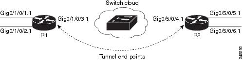
A Service Provider
network (S-network) is depicted in Figure 1. The customer network (C-network)
connects to router R1 at the GigabitEthernet subinterface 0/1/0/1.1, and to
router R2 at the GigabitEthernet subinterface 0/5/0/2.1. The C-network is not
shown in the diagram; however, the C-network sends L2 traffic through the
S-network, and the S-network switches the traffic from end to end. The customer
traffic also carries L2 protocol frames. The purpose of L2PT is to allow these
protocol frames to pass through the S-network. In forward mode, L2PT is applied
to the customer facing interfaces of the S-network, R1 GigabitEthernet
0/1/0/1.1 and R2 GigabitEthernet 0/5/0/2.1.
Figure above depicts
the configuration for L2PT in forward mode: :
Protocol traffic
enters router R1 at the GigabitEthernet subinterface 0/1/0/1.1. Router R1
detects the frames as protocol frames, and performs L2PT encapsulation at the
customer facing interface. Inside R1, the local connection
r1-connect
connects R1's customer-facing and service provider-facing interfaces. The
traffic then flows out of router R1 on GigabitEthernet subinterface 0/1/0/2.1
through several other service provider network routers or switches (switch
cloud) into router R2 at GigabitEthernet subinterface 0/5/0/1.1. Router R2
connects the customer-facing and service provider-facing interfaces through a
local connection
r2-connect. Therefore, traffic is sent to the customer-facing interface
GigabitEthernet 0/5/0/2.1. At this interface, an L2PT decapsulation occurs and
the protocol traffic flows out of router R2 into the customer network.
Without L2PT being
configured the customer protocol frames that are sent into R1 are terminated.
The customer traffic can consist of a variety of traffic; the protocol frames
comprise a small percentage of the overall traffic stream.
L2PT in the Reverse
Mode with Protocol Frame Tagging
The Cisco ASR 9000
Series Routers can perform L2PT encapsulation and decapsulation on supported L2
protocol frames that have VLAN headers. The L2 protocol frames do not have VLAN
headers. However, in a service provider (SP) network that transports customer
protocol traffic from one customer campus to another, this capability can be
put to use within the SP network.
Figure below shows
L2PT configured in the reverse mode. Assume that the customer traffic that
enters R1 is trunked, that is all traffic is tagged. The only untagged traffic
is the protocol traffic, that comes from the customer network.
Figure 2. L2PT in reverse
mode
When L2PT is
configured in the reverse mode, the L2PT encapsulation occurs when the frame
exits the interface. Likewise, in reverse mode decapsulation is performed when
the frame enters the interface. Therefore, the L2PT tunnel is formed between
the service provider-facing interfaces, instead of the customer-facing
interfaces.
In this example, once
the protocol traffic enters router R1, a VLAN tag is added to it. Before the
traffic is sent through the service provider network, a second VLAN tag is
added (100). The Cisco ASR 9000 Series Routers perform the L2PT encapsulation
on a double-tagged protocol frame.
The above figure above
shows four customer-facing interfaces (R1: GigabitEthernet subinterface
0/1/0.1.1, GigabitEthernet subinterface 0/1/0/2.1 and R2: GigabitEthernet
subinterface 0/5/0/5.1, GigabitEthernet subinterface 0/5/0/6.1) and two service
provider-facing interfaces (R1: GigabitEthernet subinterface 0/1/0/3.1 and R2:
GigabitEthernet subinterface 0/5/0/4.1).
Figure above depicts
the configuration for L2PT in reverse mode:
Customer traffic
entering router R1 is trunked, that is all traffic is tagged. The only untagged
traffic is the protocol traffic, which arrives from the customer network.
The
Customer-facing interfaces GigabitEthernet 0/1/0/1 at router R1 and Gigabit
Ethernet 0/5/0/5 at router R2 belong to the same customer. Customer-facing
interfaces GigabitEthernet 0/1/0/2 at router R1 and GigabitEthernet 0/5/0/6 at
router R2 belong to a different customer.
Traffic from
different customers remain segregated.
Only L2 protocol
traffic is sent through the customer-facing interfaces.
L2 protocol
traffic entering the customer-facing interfaces is untagged.
Traffic must be
L2PT encapsulated to successfully pass through the switch cloud.
The purpose of this
topology is that router R1 and R2 must receive customer protocol traffic from
multiple customer interfaces, and multiplex the traffic across a single service
provider interface and link. At the decapsulation end, the reverse is
performed. Traffic entering router R1 on the GigabitEthernet subinterface
0/1/0/1.1 exits router R2 from the GigabitEthernet subinterface 0/5/0/5.1 only
while traffic entering router R1 at GigabitEthernet subinterface 0/1/0/2.1
exits router R2 from GigabitEthernet subinterface 0/5/0/6.1 only.
A protocol frame
entering router R1 on GigabitEthernet interface 0/1/0/1 travels through the
network in this manner:
The protocol frame
is directed to GigabitEthernet subinterface 0/1/0/1.1, as the frame is
untagged.
The rewrite
statement with GigabitEthernet subinterface 0/1/0/1.1 causes a tag of ID 100 to
be added to the frame.
The frame enters
router R1’s bridge domain r1-bridge.
The bridge
(r1-bridge) floods the frame to all attachment circuits (AC) on the bridge
domain, except the originating AC (split horizon AC).
Ethernet egress
filtering on GigabitEthernet subinterface 0/1/0/2.1 detects a tag ID mismatch,
and drops the frame. In this way, the bridge domain’s flooded traffic is
prevented from exiting other customer interfaces.
A flooded copy of
the frame is sent to GigabitEthernet subinterface 0/1/0/3.1.
GigabitEthernet
subinterface 0/1/0/3.1 adds a second tag.
The frame receives
an L2PT encapsulation by GigabitEthernet subinterface 0/1/0/3.1 before it
leaves router R1 through the GigabitEthernet interface 0/1/0/3.
Note
The frame is
now double-tagged (100 inner, 500 outer) and has the L2PT MAC DA.
The frame passes
to router R2 GigabitEthernet interface 0/5/0/4 because of the L2PT
encapsulation.
The frame after
having entered router R2 on GigabitEthernet interface 0/5/0/4 is directed to
GigabitEthernet subinterface 0/5/0/4.1.
On entering
GigabitEthernet subinterface 0/5/0/4.1, an L2PT decapsulation operation is
performed on the frame.
The outer tag ID
500 is removed by GigabitEthernet subinterface 0/5/0/4.1
Router R2’s bridge
(r2-bridge) floods the frames to all ACs.
Ethernet egress
filtering drops the frames on all ACs except the AC through which the frame
exits.
As the frame exits
router R2 from GigabitEthernet subinterface 0/5/0/5.1, the tag of ID 100 is
removed.
The frame that
exits router R2 from GigabitEthernet interface 0/5/0/5 is identical to the
original frame that entered router R1 through GigabitEthernet interface
0/1/0/1.
L2PT Configuration Notes
Keep these points in mind while configuring L2PT:
The
l2protocol command can be configured on either a
main or L2 subinterface.
The
l2protocol command can be configured on physical
or bundle interfaces.
When the
l2protocol and
ethernet filtering commands are configured on the
same interface, L2PT encapsulation occurs before ethernet filtering. This means
that L2PT prevents the CDP, STP, and VTP protocol frames from being dropped by
ethernet filtering.
When L2PT is configured with other interface features, L2PT
encapsulation occurs before the processing for other interface features.
L2PT encapsulation and decapsulation is supported for untagged
protocol frames, single-tagged, and double-tagged frames. Tag Ethertypes of
0x8100, 0x88A8, and 0x9100 are supported, however, 0x9200 is not.
How to Implement Ethernet Features
Note
For information on configuring Ethernet interfaces, refer to the
Cisco ASR 9000 Series Aggregation Services Router Interface and
Hardware Component Configuration Guide.
Configuring Policy
Based Forwarding
Enabling Policy
Based Forwarding
Perform this task
to enable policy based forwarding.


 Feedback