Install the Router

Before you begin this task, ensure that you have read and understood the safety warnings in the Standard Warning Statements section of the Safety Warnings handout topic.

Installing the Cisco ASR-920-20SZ-M Router involves these tasks:

Rack Compatibility

We recommend that you follow these rack specifications.

Rack Types

Figure 1. Rack specification EIA (19 inches and 23 inches)
Table 1. Rack specification EIA (19 inches and 23 inches)

Post Type

Rack Type

Rack Front Opening (X)

Rack Mounting Hole Centre-Centre (Y)

Mounting Flange Dimension (Z)

4 Post

19 inches (48.3 centimeters)

17.75 inches (45 centimeters)

18.31 inches (46.5 centimeters)

19 inches (48.2 centimeters)

2 Post

4 Post

23 inches (58.4 centimeters)

21.75 inches (55.24 centimeters)

22.31 inches (56.6 centimeters)

23 inches (58.4 centimeters)

2 Post

Figure 2. Four Post Rack Type
Figure 3. Two Post Rack Type

Set up Device on Rack or Wall

You can choose to either set up the Cisco ASR 920 Router on a rack or wall mount it.

Rack Mount

You can choose to either set up the router in a horizontal or a vertical mounting position on the rack.

Install Rack Brackets

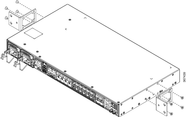
The device is shipped with rack mounting brackets that are to be secured on the sides of the device.

Procedure

Step 1

Remove the rack mounting brackets from the accessory kit and position them beside the device.

Note

 
You can install the brackets at any of the 3 positions that are shown in the figure.
Figure 4. Attaching Mounting Brackets to Router for a 19-inch EIA Rack (Front Position)
Figure 5. Attaching Mounting Brackets to Router for a 19-inch EIA Rack (Middle Position)
Figure 6. Attaching Mounting Brackets to Router for a 19-inch EIA Rack (Rear Position)
Figure 7. Attaching Mounting Brackets to Router for a 23-inch EIA Rack (Front Position)
Figure 8. Attaching Mounting Brackets to Router for a 23-inch EIA Rack (Middle Position)
Figure 9. Attaching Mounting Brackets to Router for a 23-inch EIA Rack (Rear Position)
Figure 10. Attaching Mounting Brackets to Router for a ETSI Rack (Front Position)
Figure 11. Attaching Mounting Brackets to Router for a ETSI Rack (Middle Position)
Figure 12. Attaching Mounting Brackets to Router for a ETSI Rack (Rear Position)

Step 2

Secure the bracket to the device with the recommended maximum torque of 10 inch-pounds (1.1 newton meters).


Set up Device on Rack


Note


Ensure adequate clearance when mounting the device on a rack.

Note


Install cable guides before installing the device in a 19 inches (48.3 centimeters) EIA rack.
Procedure

Step 1

Position the device on the rack, and use the images as a guide to set up the device.

Figure 13. Set up Device on Rack

Step 2

Use a tape measure and level to verify that the device is installed straight and on level.


Attaching the Cable Guides


Note


If the chassis is mounted using 19-inch brackets, you must assemble the cable guides before installing the chassis on the rack.
Procedure

Step 1

Position the cable A920-CBL-GUIDE (left and right) against the front of the chassis and align the two screw holes, as shown in the figure.

Figure 14. Attach Cable Guides

Step 2

Secure the cable guides with the two M6x12mm screws supplied with the cable kit. The recommended maximum torque is 26 inch-pounds (3 newton meters).


Wall Mount

Install the wall mounting brackets and cable guides on to the chassis before you mount the chassis on the wall.

Install Wall Brackets

The device is shipped with wall mounting brackets that are to be secured on the sides of the device.

Procedure

Step 1

Remove the wall mounting brackets from the accessory kit and position them beside the device.

Note

 
You can install the brackets as shown in the figure.
Figure 15. Wall Mount Bracket

Step 2

Secure the bracket to the device with the recommended maximum torque of 10 inch-pounds (1.1 newton meters).


Wall Mount the Device


Note


Install cable guides before mounting the device on the wall.
Procedure

Step 1

Position the cable guide against the front of the device, and align the four screw holes as shown in the figure.

Step 2

Use a tape measure and level to verify that the device is installed straight and on level.

Step 3

Secure the cable guides with four M6x12mm screws that are supplied with the cable kit. The recommended maximum torque is 26 inch-pounds (3 newton meters).

Step 4

Position the device vertically on the wall.

Figure 16. Mounting the Router on the Wall

Caution

 
Before mounting the device, ensure that all unused holes at the sides of the device are protected with screws.

Ground the Device

Before you begin this task, ensure that you have read and understood the safety warnings in the Preventing ESD Damage section of the Safety Warnings handout topic.

Before you connect the power or turn on the power to the device, you must provide an adequate device ground (earth) connection to your device.

This section describes how to ground the device. The grounding lug location is on the back panel of the device.


Tip


Ensure that the grounding lug wire does not cover the fan opening.


Figure 17. Attach a Ground Lug to the Rear of the Device

Caution


To prevent personal injury or damage to the chassis, before making connections to the device, ensure that you disconnect the power at the circuit breaker.


Verify your carrier’s requirements for grounding. This unit must be installed in a restrictive access location and must be permanently grounded to a minimum 6-AWG copper ground wire.

Procedure


Step 1

If your ground wire is insulated, use a wire-stripping tool to strip the ground wire to 0.5 inch (12.7 millimeters) ± 0.02 inch (± 0.5 millimeters).

Figure 18. Stripping a Ground Wire


Step 2

Slide the open end of the 2-hole ground lug over the exposed area of the ground wire.

Step 3

Using a crimping tool (the one specified by the ground lug manufacturer), crimp the ground lug to the ground wire.

Step 4

Use a Phillips head screwdriver to attach the 2-hole ground lug and wire assembly to the device with the 2 pan-head Phillips head screws.

Step 5

Connect the other end of the ground wire to a suitable grounding point at your site.


Connect Power Cables

Before you begin this task, ensure that you have read and understood the safety warnings in the Safety with Electricity section of the Safety Warnings handout topic.

The Cisco ASR-920-20SZ-M Router supports both AC and DC power supplies. Based on your device power supply, attach the AC and the DC power cables.

Activating an AC Power Supply

Follow these steps to activate an AC power supply:

Procedure


Step 1

Attach the AC power retainer cord as shown in the figure below.

Figure 19. Attaching the AC Power Retainer Cord

Step 2

Lift the power retainer and plug in the AC power supply.

Step 3

Push the retainer clip towards the power cord until it rests on the boot, this ensures accidental removal or drop-off of the power cord.

Figure 20. Locking the Power Retainer Cord

Step 4

Connect the other end of the power cord to an AC-input power source.

Step 5

Verify power supply operation by checking that the power supply LED is green.

Step 6

If the LEDs indicate a power problem, see LED Indicators section for troubleshooting information.

Step 7

If you are installing a redundant power supply, repeat these steps for the second power source.

Note

 
If you are installing a redundant AC power supply, ensure that each power supply is connected to a separate power source in order to prevent power loss in the event of a power failure.

Attach Cables to the DC Power Supply


Note


When installing DC power supply, use 14 AWG, 90°C wires. Always ensure that the building’s installation for short-circuit (overcurrent) protection does not exceed 15A.

To attach the DC power supplies:

Procedure


Step 1

Open the DC power supply guard.

Step 2

Attach the DC supply wires in the designated screws. See the figure below.

Figure 21. Connecting the DC Power Supply Wires

Step 3

Close the DC power supply guard.


Power On the DC Power Supply

After the router is either rack mounted or mounted on the wall, perform these tasks to complete the installation:

Procedure


Step 1

Power on the DC power supply. See the figure below.

Figure 22. Powering on the DC Power Supply

1

power on/off switch

Step 2

Connect the front-panel ports.


Connect Gigabit Ethernet Ports

Gigabit Ethernet (GE) ports can be connected to other devices using either fiber optic or copper cables. The choice depends on whether the communication distance between your devices is long or short.

If you choose fiber optic cables, connect suitable Small Form-factor Pluggable (SFP) modules. The device supports various SFP and SFP+ modules, including optical and Ethernet modules. For information on how to install and remove SFP and SFP+ modules, see the documentation for the SFP or SFP+ module at: Cisco SFP and SFP+ Transceiver Module Installation Notes. Select the port on the device where you insert the SFP module.

If you choose copper cables, connect to an RJ-45 connector.

The device 10/100/1000 ports configure themselves to operate at the speed of devices to which they are connected. By default, autonegotiation is enabled in the chassis. You can manually set the speed and the duplex parameters. If the device to which the ports are connected does not autonegotiate, low performance or no linkage may result.

To maximize performance, choose one of these methods for configuring the GE ports:

  • Have ports autonegotiate both speed and duplex parameters.
  • Set speed and duplex parameters on both ends of the connection.

Use the mdix auto command in the interface configuration mode to enable an automatic media-dependent interface with crossover detection. After you enable the automatic media-dependent interface, the device detects the required cable type for copper Ethernet connections and configures the interface accordingly. Then, use either a crossover or a straight-through cable for connecting to a copper 10/100/1000 port. If the mdix auto command fails to enable the interface, connect the cable through SFP modules.

Connect SFP Modules

Before you begin this task, ensure that you have read and understood the safety warnings in the Safety Precautions for Module Installation and Removal section of the Safety Warnings chapter.

Use only Cisco SFP modules on a Cisco device. Each SFP module has an internal serial EEPROM that is encoded with security information. This encoding provides a way for Cisco to identify and validate that the SFP modules meet the requirements of the device.


Caution


We recommend that you wait for 30 seconds between the removal and insertion of an SFP module from the device. The wait period allows the transceiver software to initialize and synchronize with the device. Changing an SFP before this wait period could result in transceiver initialization issues that disable the SFP.


This section provides procedures for installing and connecting SFP modules. Also, it provides the procedure for removing SFP modules.

Install SFP Modules


Caution


We strongly recommend that you do not install (or remove) an SFP module with its cables connected because of the potential damage that may be caused to the cables, the cable connector, or the optical interfaces in the SFP modules. Disconnect all cables before removing or installing an SFP module.

Removing and installing an SFP module can shorten its useful life. Do not remove and insert SFP modules unless necessary.


The following figure shows an SFP module that has a bale-clasp latch.

Figure 23. SFP Module with Bale-Clasp Latch


Some SFP modules identify the top side of the module with send (TX) and receive (RX) has markings or arrows that show the direction of the connection. If the SFP module that you are using has such markings, use them to identify the top of the module.

Procedure

Step 1

Attach an ESD-preventive wrist strap to your wrist and to a bare metal surface on the chassis.

Step 2

Align the SFP module at the front of the slot opening.

Step 3

Insert the SFP module into the slot until the connector on the module snaps into place at the rear of the slot.

Caution

 
Do not remove the dust plugs from the fiber-optic SFP module port or the rubber caps from the fiber-optic cable until you are ready to connect the cable. The plugs and caps protect the SFP module ports and cables from contamination and ambient light. Store the dust plugs for later use.

Step 4

Insert the appropriate cable connector into the SFP module:

  • For fiber-optic SFP modules, insert the LC cable.

  • For copper 1000BASE-T SFP modules, insert the RJ-45 cable.


Remove SFP Modules

Follow these steps to remove an SFP module when it is necessary.

Procedure

Step 1

Attach an ESD-preventive wrist strap to your wrist and to a bare metal surface on the chassis.

Step 2

Disconnect the cable from the SFP module, and insert a dust plug into the cable end.

Step 3

Unlock and remove the SFP module.

If the module has a bale-clasp latch, pull the bale down and out to eject the module. If the bale-clasp latch is obstructed, use a small, flat-blade screwdriver or any other narrow instrument to open the bale-clasp latch.

Step 4

Grasp the SFP module between your thumb and index finger, and carefully remove it from the module slot.

Step 5

For fiber-optic SFP modules, insert a dust plug into the optical ports of the SFP module to keep the optical interfaces clean.

Step 6

Place the removed SFP module in an antistatic bag or other protective environment.

For information about inspecting and cleaning fiber-optic connections, see: Inspection and Cleaning Procedures for Fiber-Optic Connections.


Connect Fiber Optic SFP Modules


Caution


Do not remove the rubber plugs from the SFP module port or from the fiber optic cable until you are ready to connect the cable. The plugs and caps protect the SFP module ports and cables from contamination and ambient light.


Procedure

Step 1

Remove the rubber plugs from the module port and fiber optic cable, and store them for future use.

Step 2

Insert one end of the fiber optic cable into the SFP module port.

Step 3

Insert the other end into a fiber optic connector at a target device.

Step 4

Observe the port's LED status.

The LED turns green when the device and the target device establish a link.

If the LED is off, check whether the target device is turned on, or whether there is any failure in the target device.

Step 5

If necessary, reconfigure and restart the device or target device.


Connect RJ-45 Connector

Procedure


Step 1

To connect to workstations, servers, and devices, connect a straight-through cable to an RJ-45 connector at the front panel.

When connecting to devices or repeaters, use a crossover cable.

Step 2

Connect the other end of the cable to an RJ-45 connector at the other device. The port's LED turns on when both the device and the connected device have established a link.

If the port LED does not turn on, check whether the device at the other end is turned on or whether there is any failure.

Note

 
On user network interface (UNI) ports, the port LED turns green after the link is established.

Step 3

Reconfigure and reboot the connected device if necessary.

Step 4

Repeat Steps 1 to 3 for each device that is to be connected.


Connect Chassis to Network


Note


Connect only SELV services to all the device ports.

Connecting Console Cables

This section describes how to connect to the Cisco ASR 920 Router using console cables:

Connecting to the USB Serial Port Using Microsoft Windows

This procedure shows how to connect to the USB serial port using Microsoft Windows.


Note


Install the USB device driver before establishing a physical connection between the router and the PC, by plugging the USB console cable into the USB serial port. Otherwise, the connection fails. For more information, see the Installing the Cisco USB Device Driver section.
Procedure

Step 1

Connect a USB Type A-to-Type A cable to the USB console port, as shown in figure. If you are using the USB serial port for the first time on a Windows-based PC, install the USB driver now according to the instructions in the following sections:

  • Installing the Cisco USB Device Driver

  • Uninstalling the Cisco USB Device Driver

Note

 
You cannot use the USB port and the EIA port concurrently. When the USB port is used, it takes priority over the EIA port.

Step 2

Connect the USB Type A cable to the PC.

Step 3

To communicate with the router, start a terminal emulator application, such as Microsoft Windows HyperTerminal. Configure the software with the following parameters:

  • 9600 baud

  • 8 data bits

  • no parity

  • 1 stop-bit

  • no flow control

Figure 24. Connecting the USB Console Cable to the Cisco ASR 920 Router

Label

Cable

Label

Cable

1

USB Type-A console port

2

USB USB Type-A to USB Type-A console cable


Connecting to the Console Port Using Mac OS X

This procedure describes how to connect a Mac OS X system USB port to the console using the built-in OS X terminal utility.

Procedure

Step 1

Use the Finder to choose Applications > Utilities > Terminal.

Step 2

Connect the OS X USB port to the router.

Step 3

Enter the following commands to find the OS X USB port number:

Example:

macbook:user$ cd /dev
macbook:user$ ls -ltr /dev/*usb*
crw-rw-rw-  1 root  wheel   19,   6 Dec  9 16:25 /dev/tty.usbmodem1411
crw-rw-rw-  1 root  wheel   19,   7 Dec  9 16:25 /dev/cu.usbmodem1411DT-macbook:dev user$

Step 4

Connect to the USB port with the following command followed by the router USB port speed:

Example:

macbook:user$ screen /dev/tty.usbmodem1411 9600

To disconnect the OS X USB console from the terminal window, enter Ctrl-a followed by Ctrl-\


Connecting to the Console Port Using Linux

This procedure shows how to connect a Linux system USB port to the console using the built-in Linux terminal utility.

Procedure

Step 1

Open the Linux terminal window.

Step 2

Connect the Linux USB port to the router.

Step 3

Enter the following commands to find the Linux USB port number:

Example:

root@usb-suse# cd /dev
root@usb-suse /dev# ls -ltr *ACM*
crw-r--r--    1 root     root     188,   0 Jan 14 18:02 ttyACM0
root@usb-suse /dev#

Step 4

Connect to the USB port with the following command, followed by the router USB port speed:

Example:

root@usb-suse /dev# screen /dev/ttyACM0 9600

To disconnect the Linux USB console from the terminal window, enter Ctrl-a followed by : then quit


Installing the Cisco USB Device Driver

A USB device driver must be installed the first time a Microsoft Windows-based PC is connected to the USB serial port on the router.

This procedure describes how to install the Microsoft Windows USB device driver in Microsoft Windows XP / Windows Vista / Windows 2000 / Windows 7 / Windows 8. Download the driver for your router model from the Tools and Resources Download Software site, USB Console Software category.


Note


To Download the driver, you must have a valid service contract associated to your Cisco.com profile.
Procedure

Step 1

Unzip the file asr-9xx_usbconsole_drivers.zip.

Step 2

Double-click xrusbser_ver2100_installer.exe in the XR21x141x-Win-DriversOnly-Vers2.1.0.0/EXE folder. Installation Wizard GUI is displayed.

Step 3

Click Next. The InstallShield Wizard Completed window is displayed.

Step 4

Click Finish.

Step 5

Connect the USB cable to the PC and router USB console ports. Follow the on-screen instructions to complete the installation of the driver.

Step 6

XR21V1401 USB UART Device driver successfully installed message is displayed.

The USB console is ready for use.


Uninstalling the Cisco USB Device Driver

This procedure describes how to uninstall the Microsoft Windows USB device driver in Microsoft Windows XP / Windows Vista / Windows 2000 / Windows 7 / Windows 8.


Note


Disconnect the router console terminal before uninstalling the driver.
Procedure

Step 1

Choose Start > Control Panel > Add or Remove Programs (Uninstall a program).

Step 2

Scroll to Windows Driver Package - Exar corporation (xrusbser) Ports and click Remove. The Program Maintenance window is displayed.

Step 3

Click Yes to uninstall the driver.


Connecting a USB Flash Device

To connect a USB flash device to the Cisco ASR 920 Router, insert the memory stick in the USB port labeled USB MEM. The flash memory module can be inserted only one way, and can be inserted or removed regardless of whether the router is powered up or not.

The following figure shows the USB port connector on the Cisco ASR 920 Router.

Figure 25. Cisco ASR 920 Router Flash Token Memory Stick

Removing a USB Flash Device

To remove and replace a USB flash token memory stick from and into a Cisco ASR 920 Router, follow these steps:


Note


If the USB flash device is abruptly removed, the constant sync operations of the file system in progress fail due to the USB device removal. These errors occur with ext2 or ext3 or ext4 file systems and are not seen with fat32 file system. This is a default behavior on any Linux platform.

The following error messages are displayed when you remove the USB device:

*Jun 24 10:29:45.766: %IOSXE-3-PLATFORM: R0/0: kernel: EXT2-fs (sda1): previous I/O error to superblock detected 
*Jun 24 10:29:45.878: %IOSXE-3-PLATFORM: R0/0: kernel: EXT2-fs (sda1): previous I/O error to superblock detected 
*Jun 24 10:29:46.012: %IOSXE-3-PLATFORM: R0/0: kernel: EXT2-fs (sda1): previous I/O error to superblock detected 
*Jun 24 10:29:46.013: %IOSXE-3-PLATFORM: R0/0: kernel: EXT2-fs (sda1): previous I/O error to superblock detected 

Procedure

Step 1

Execute the eject usb0: command before removing the USB from the router.

Example:
rommon 2 > eject usb0
rommon 2 >

If you do not run this command before removing the USB, the following error message is displayed:

rommon 2 > dir usb0:
  usb_stor_BBB_comdat:usb_bulk_msg error
  failed to send CBW status 34
  RESET:stall
  usb_stor_BBB_comdat:usb_bulk_msg error
  failed to send CBW status 34
  RESET:stall
  usb_stor_BBB_comdat:usb_bulk_msg error

Step 2

Pull the memory stick from the USB port.

Step 3

To replace the Cisco USB flash memory stick, simply insert the module into the USB port labeled USB MEM, as shown in figure. The flash memory module can be inserted only one way, and can be inserted or removed regardless of whether the router is powered up or not.

This completes the USB flash memory installation procedure.


Connecting Timing Cables

The sections describe how to connect timing cables to the Cisco ASR 920 Router:


Warning


To comply with the Telcordia GR-1089 NEBS standard for electromagnetic compatibility and safety, connect the ToD ports only to intra-building or unexposed wiring or cable. The intrabuilding cable must be shielded and the shield must be grounded at both ends. The intra-building port(s) of the equipment or subassembly must not be metallically connected to interfaces that connect to the OSP or its wiring. These interfaces are designed for use as intra-building interfaces only (Type 2 or Type 4 ports as described in GR-1089-CORE) and require isolation from the exposed OSP cabling. The addition of Primary Protectors is not sufficient protection in order to connect these interfaces metallically to OSP wiring.


Connecting a Cable to the BITS Interface

The following steps describe how to connect a cable to the router’s BITS port:

Procedure

Step 1

Confirm that the router is powered off.

Step 2

Connect one end of the cable to the BITS port using a straight-through, shielded RJ48C-to-RJ48C cable.

Step 3

Connect the other end to the BTS patch or demarcation panel at your site.

Step 4

Turn on the power to the router.

For information about the BITS port pinouts, see the Troubleshooting section.


Connecting Cables to the GPS Interface

The sections describe how to connect cables from the Cisco ASR 920 Router to a GPS unit for input or output timing of frequency:


Note


When installing the cables to the RSP, we recommend that you leave a service loop of extra cable to enable fan tray removal.
Connecting a Cable to the Input 10-Mhz or 1-PPS Interface
Procedure

Step 1

Connect one end of a shielded mini-coax cable to the GPS unit.

Step 2

Connect the other end of the shielded mini-coax cable to the 10-Mhz or 1-PPS port on the RSP of the Cisco ASR 920 Router.


Connecting a Cable to the Output 10-Mhz or 1-PPS Interface
Procedure

Step 1

Connect one end of a shielded mini-coax cable to the Slave unit.

Step 2

Connect the other end of the shielded mini-coax cable to the 10-Mhz or 1-PPS port on the RSP of the Cisco ASR 920 Router.


Connecting a Cable to the ToD Interface
Procedure

Step 1

Connect one end of a straight-through Ethernet cable to the GPS unit.

Step 2

Connect the other end of the straight-through Ethernet cable to the ToD or 1-PPS port on the RSP of the Cisco ASR 920 Router.

Note

 
For instructions on how to configure clocking, see the Cisco ASR 920 Series Aggregation Services Routers Configuration Guide.

Connect to EIA Console Port


Note


The serial console cable kit is not included with the device; it must be ordered separately.

Procedure


Step 1

Connect the RJ-45 cable to the EIA Console port.

Step 2

Connect the DB-9 end of the console cable to the DB-9 end of the terminal.

Step 3

To communicate with the device, start a terminal emulator application, such as Microsoft Windows Hyper-Terminal. Configure the software with the following parameters:

  • 9600 baud

  • 8 data bits

  • No parity

  • 1 stop-bit

  • No flow control


Connect a Management Ethernet Cable

When using the Ethernet Management port in the default mode (speed-auto and duplex-auto), the port operates in the auto-MDI/MDI-X mode. The port automatically provides the correct signal connectivity through the Auto-MDI/MDI-X feature, and senses a crossover or straight-through cable and adapts to it.

However, the Ethernet Management port may be configured to a fixed speed (10, 100, or 1000 Mbps) through command-line interface (CLI) commands. In such a case, the port is forced to operate in the MDI mode.

When in a fixed-speed configuration and MDI mode, use:

  • a crossover cable to connect to an MDI port
  • a straight-through cable to connect to an MDI-X port