Install and Upgrade Internal Modules and FRUs

This document describes how to install and upgrade internal modules and field replaceable units (FRUs) in the Cisco Catalyst 8500L-8S4X Edge Platform. The install and upgrade information is contained in these sections:

Safety Warnings


Warning


Statement 343—Before Making Telecommunication Network Connection

High touch/leakage current – Permanently connected protective earth ground is essential before connecting to telecommunication network.


Warning


Class 1 laser product. Statement 1008


Warning


To reduce the risk of electric shock, the chassis of this equipment needs to be connected to permanent earth ground during normal use. Statement 0445

Warning


To reduce risk of electric shock and fire, a readily accessible two-poled disconnect device must be incorporated in the fixed wiring. Statement 1022

Warning


Only trained and qualified personnel should be allowed to install, replace, or service this equipment. Statement 1030

Warning


Invisible laser radiation may be emitted from disconnected fibers or connectors. Do not stare into beams or view directly with optical instruments. Statement 1051


Warning


Invisible laser radiation may be emitted from the end of the unterminated fiber cable or connector. Do not view directly with optical instruments. Viewing the laser output with certain optical instruments (for example, eye loupes, magnifiers, and microscopes) within a distance of 100 mm may pose an eye hazard. Statement 1056


Warning


Only instructed person or skilled person should be allowed to install, replace, or service this equipment. Refer to statement 1089 for description of skilled person.


Warning


Only instructed person or skilled person should be allowed to install, replace, or service this equipment. Refer to statement 1089 for description of skilled person. Statement 1090


Warning


Only instructed person or skilled person should be allowed to install, replace, or service this equipment. Refer to statement 1089 for description of skilled person. Statement 1091


Warning


Pluggable optical modules comply with IEC 60825-1 Ed. 3 and 21 CFR 1040.10 and 1040.11 with or without exception for conformance with IEC 60825-1 Ed. 3 as described in Laser Notice No. 56, dated May 8, 2019.. Statement 1255


Locate and Access Internal Modules

The figures below show the locations of internal modules on the motherboard. Internal modules include DIMMs and fan tray on Cisco Catalyst 8500L-8S4X Edge Platform.

To access the internal modules on the device, you must first remove the chassis cover. For instructions on how to remove and replace the chassis cover on the device, see the sections on Install and Remove Chassis Covers.

Figure 1. Internal Module Locations in the C8500L-8S4X

1

DIMM

2

Fan tray

Remove and Replace the Chassis Cover

The Cisco Catalyst 8500L-8S4X Edge platform have removable covers. Before removing the cover, note the following:

  • Do not run the router with the cover off. Doing so can cause the router to overheat very quickly.

  • Before opening the unit, disconnect the telephone-network cables to avoid contact with telephone-network voltages. Statement 1041.

  • Disconnect all power cables.

  • Remove the device from the rack

  • Use a number-2 Phillips screwdriver to perform the following tasks.

Remove the Chassis Cover

To remove the cover, perform the following steps.

Procedure

Step 1

Read the Safety Warnings and disconnect the power supply before you perform any module replacement.

Step 2

Confirm the device is turned off and disconnected from the power supply or power supplies. If a redundant power is used, disconnect from the redundant power supply.

Step 3

Place the chassis on a flat surface.

Step 4

Remove the 11 cover screws.

Step 5

Lift the cover straight up.


Replace the Cover

To replace the cover, perform the following steps.

Procedure

Step 1

Place the chassis on a flat surface.

Step 2

Drop the cover straight down and ensure that the side flanges insert into the chassis. Care should be taken to not damage the EMC Gaskets.

Note

 
The correct orientation iof the cover s determined by location of the CISCO logo as shown in image below.

Step 3

Install the 11 cover screws.

Figure 2. Install the Cover on the C8500L-L8S4X

1

Chassis cover

2

Screws


Remove and Replace DDR DIMMs

To access the DIMMs, you must remove the chassis cover as described in the Access and Install Modules section.


Caution


Always wear an ESD-preventive wrist strap and ensure that it makes good contact with your skin when you remove or install DIMMs. Connect the equipment end of the wrist strap to the metal part of the chassis.


Caution


Handle DIMMs by the edges only. DIMMs are ESD-sensitive components and can be damaged by mishandling.


Locate and Orient DIMM

DIMMs have a polarization notch on the mating edge to prevent incorrect insertion. The following image shows the polarization notch on a DIMM.

Figure 3. DIMM Showing Polarization Notch

1

Polarization notch

Remove a DIMM

Follow these steps to remove a DIMM:

Procedure


Step 1

Read the Safety Warnings section and disconnect the power supply before you perform any module replacement.

Step 2

Remove the chassis cover. See the Remove the Chassis Cover section

Step 3

Locate the DIMM module to find the DIMM sockets on the chassis.

Step 4

Rotate DIMM connector handles downwards to extract the DIMM module.

Figure 4. Remove a DIMM

Install a DIMM

Follow these steps to install a DIMM on the Cisco Catalyst 8500L-8S4X Edge device.

Procedure


Step 1

Read the Safety Warnings section and disconnect the power supply before you perform any DIMM replacement.

Step 2

Remove the chassis cover.

Step 3

Locate the DIMM module to find the DIMM sockets on the device.

Step 4

Ensure that both latches on the DIMM connector are in the open position.

Step 5

Orient the DIMM so that the polarization notch lines up with the polarization key on the connector.

Figure 5. DIMM Showing Polarization Notch

Step 6

Insert the DIMM into the connector one side at a time.

Step 7

Rotate the connector handles upward and click into place.

Figure 6. Install a DIMM

Step 8

Replace the chassis cover.


Remove and Replace the Power Supplies


Warning


Blank faceplates and cover panels serve three important functions: they prevent exposure to hazardous voltages and currents inside the chassis; they contain electromagnetic interference (EMI) that might disrupt other equipment; and they direct the flow of cooling air through the chassis. Do not operate the system unless all cards, faceplates, front covers, and rear covers are in place. Statement 1029

Warning


This unit has more than one power supply connection. All connections must be removed to de-energize the unit. Statement 1028

Note


If a PSU which is failed is removed, a PSU-blank must be installed in the slot until a new PSU is installed.


Figure 7. Power Supply Blank

Sl. No

Module

1

Latch

Figure 8. Power Supply Unit of C8500L-8S4X

Sl. No

Module

1

Slot for PSU1

2

PSU1

3

Slot for PSU0

4

PSU0

AC Power Supplies

Overview of the AC Power Supply

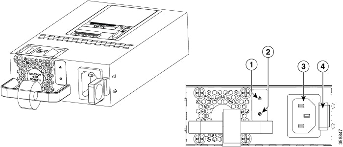
Figure 9. 400W AC Power Supply for C8500L-8S4X

1

Alarm Fail LED

2

Status LED

3

AC socket

4

Latch

Installing AC Power Supplies


Note


Do not install the power supplies with the chassis cover off.


Procedure


Step 1

Ensure that the chassis power switch on the chassis is in the Standby position.

Note


It is not required to place the chassis power switch in the Standby position if you want to hot-swap a single power supply.

Step 2

Insert the power supply module into the appropriate slot(s), making sure that the retention latch is firmly placed. You can verify that the power supply module is firmly latched by gently pulling the power supply handle.

Step 3

Insert the power supply cables firmly into the power supplies.

Note


Ensure that both power supplies are inserted firmly and the power cords are in place.

Step 4

If you have changed the chassis power switch to the Standby position in Step 1, press the power switch to the On position.

The power supply LEDs are illuminated (green).


Replace the AC and HVAC or HVDC Power Supply in the C8500L-8S4X


Note


The device has redundant power supplies that can be hot-swapped.


To remove an AC power supply from the C8500L-8S4X, perform these steps:

Procedure


Step 1

Read the safety warnings section of this document.

Step 2

If there is only one power supply in the system, shut down the device before removing the power supply.

Step 3

If there are redundant power supplies in use the device does not have to be shut down prior to replacing the power supply. The power supply can be replaced while the device is in service.

Step 4

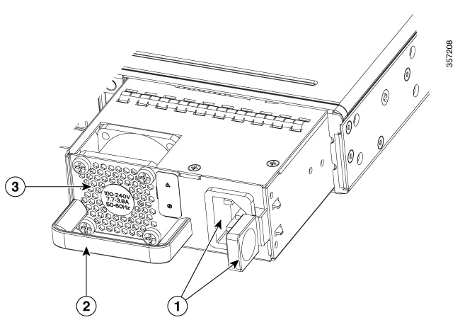
If in use, remove the strain relief securing the power supply cable to the power supply latch.

Step 5

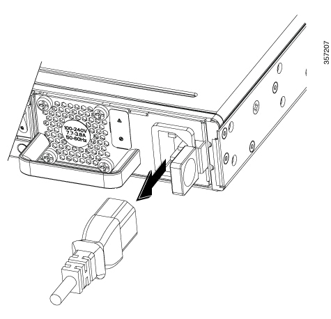
Remove the power cord from the power socket.

Step 6

Depress the power supply latch and use the handle to pull the supply out of the router.

Figure 10. Step 4

Figure 11. Step 5

Figure 12. Step 6

DC Power Supplies

Overview of the DC Power Supply

This section describes how to install the DC power supply input power that leads to the DCinput power supply. Before you begin, read these important notices:


Note


The device has redundant power supplies that can be hot-swapped.


The DC input connector has negative(-) on left and positive(+) on right with mark.

The power supply has a handle to be used for insertion and extraction. The module must be supported with one hand because of its length.

Figure 13. DC Power Supply for C8500L-8S4X

400W DC

1

Status LED

2

Alarm Fail LED

3

DC terminals

4

Handle

5

Latch

Installing DC Input Power Supplies


Note


Do not install the power supplies with the chassis cover off.


To reduce risk of electric shock, before performing any of the following procedures, ensure that power is removed from the system.

Only trained and qualified personnel should be allowed to install, replace, or service this equipment.

Do not install the power supplies with the chassis cover off.

This section describes how to install the DC power supply input power leads to the DC input power supply. Before you begin, read these important notices:

  • The color coding of the DC input power supply leads depends on the color coding of the DC power source at your site. Ensure that the lead color coding you choose for the DC input power supply matches the lead color coding used at the DC power source and verify that the power source is connected to the negative (–) terminal and to the positive (+) terminal on the power supply.

  • Ensure that the chassis ground is connected on the chassis before you begin installing the DC power supply. Follow the steps provided in the Chassis Ground Connection section.

  • For DC input power cables, the wire gauge is based on the National Electrical Code (NEC) and local codes for 15 amp service at nominal DC input voltage (40/72 VDC). One pair of cable leads, source DC (–) and source DC return (+), are required for each power distribution unit (PDU). These cables are available from any commercial cable vendor. All DC input power cables for the chassis should be at least 14 gauge wire for less than 10 feett cable length. For greater than 10 feet cable length, 12 and bigger gauge wire is recommended. The cable lengths for positive and negative should match within 10 percent of deviation.

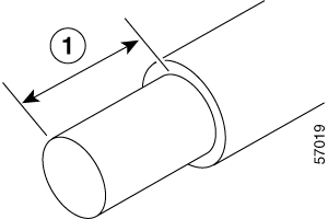
Each DC input power cable is terminated at the PDU by a cable lug, as shown in the following figure.


Note


DC input power cables must be connected to the PDU terminal studs in the proper positive (+) and negative (–) polarity. In some cases, the DC cable leads are labeled, which is a relatively safe indication of the polarity. However, you must verify the polarity by measuring the voltage between the DC cable leads. When making the measurement, the positive (+) lead and the negative (–) lead must always match the (+) and (–) labels on the power distribution unit.


Figure 14. DC Input Power Cable Lug

Note


To avoid hazardous conditions, all components in the area where DC input power is accessible must be properly insulated. Therefore, before installing the DC cable lugs, be sure to insulate the lugs according to the manufacturer's instructions.


Remove and Replace the DC Power Supply

The device has redundant power supplies that can be hot-swapped.

This section describes how to remove a DC power supply from C8500L-8S4X

Follow these steps:

Procedure


Step 1

Read the safety warnings section of this document.

Step 2

If there is only one power supply in the system, shut down the device before removing the power supply.

Step 3

If there are redundant power supplies in use the device does not have to be shut down prior to replacing the power supply. The power supply may be replaced while the device is in service.

Step 4

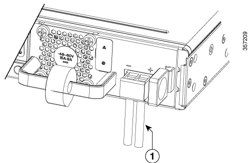
At the power distribution panel or at the local circuit breaker, remove the power from the DC power leads (label 1)attached to the power supply to be replaced.

Step 5

Remove the terminal block cover and loosen the terminal screws (label 1) securing the power cabling. Remove the power cabling from the terminal block.

Step 6

Depress the power supply latch and use the handle to pull the supply out of the device.

Figure 15. Remove a DC Power Supply from the C8500L-8S4X

Figure 16. Step 6
Figure 17. Step 7

This completes the procedure for removing a DC power supply from the C8500L-8S4Xdevice.


Wire the DC Input Power Source


Warning


Statement 1046—Installing or Replacing the Unit

To reduce risk of electric shock, when installing or replacing the unit, the ground connection must always be made first and disconnected last.


In the C8500L-8S4X platform, the DC power supply has a terminal block that is installed into the power supply terminal block header.

Use the following steps to wire the DC input power source:

Procedure


Step 1

Turn off the circuit breaker from the power source to be connected to the power source.

Step 2

Insert the power module in the power-supply slot, and gently push it into the slot.

  • The DC power supply (excluding the extraction handle) is flushed with the device.

Step 3

Wire can be stripped and terminated directly to the power supply terminal block, or a crimp style spade terminal lug can be used. If using a terminal lug follow the manufacturer's instructions for terminating the lug to the wire. If terminating directly to the terminal block using bare wire, following the below directions. Use a wire-stripping tool to strip each of the two wires coming from the DC input power source and strip the wires to approximately 0.39 inch (10 mm) + 0.02 inch (0.5 mm). It it recommended that 14 AWG insulated wire be used. Do not strip more than the recommended length of wire because doing so could leave the wire exposed from the terminal block and shows a stripped DC input power source wire.

Figure 18. Stripped DC Input Power Source Wire

1

0.39 inch (10 mm) is the recommended wire-strip length for the terminal block.

Warning


An exposed wire lead from a DC input power source can conduct harmful levels of electricity. Be sure that no exposed portion of the DC input power source wire extends from the terminal block. Statement 122

Step 4

Identify the positive and negative feed positions for the terminal block connection.

  1. Positive (+) lead wire (right)

  2. Negative (–) lead wire (left)

Step 5

Remove the terminal block cover.

Step 6

Insert the exposed wire into the terminal block. Ensure that you cannot see any wire lead outside the plastic cover. Only wires with insulation should extend from the terminal block.

Caution


Do not overtorque the terminal block captive screws. Ensure that the connection is snug, but the wire is not crushed. Verify by tugging lightly on each wire to ensure that they do not move.

Step 7

Use a screwdriver to tighten the terminal block captive screws.

Figure 19. DC Power Supply with Lead Wires

1

Negative (–) lead wire

2

Positive (+) lead wire

Step 8

Repeat these steps for the remaining DC input power source wire as applicable.

Step 9

Use a tie wrap to secure the wires to the rack, so that the wires are not pulled from the terminal block by casual contact.

Step 10

Turn on the circuit breaker at the power source.


HAVC Power Supplies

Overview of HVAC Power Supply

Figure 20. 400W HVAC Power Supply for C8500L-8S4X

1

Status LED

2

HVAC/HVDC socket

3

latch

Installing HVAC Power Supplies


Note


Do not install the power supplies with the chassis cover off.


Procedure


Step 1

Ensure that the chassis power switch on the chassis is in the Standby position.

Note


It is not required to place the chassis power switch in the Standby position if you want to hot-swap a single power supply.

Step 2

Insert the power supply module into the appropriate slot(s), making sure that the retention latch is firmly placed. You can verify that the power supply module is firmly latched by gently pulling the power supply handle.

Step 3

Insert the power supply cables firmly into the power supplies.

Note


Ensure that both power supplies are inserted firmly and the power cords are in place.

Step 4

If you have changed the chassis power switch to the Standby position in Step 1, press the power switch to the On position.

The power supply LEDs are illuminated (green).


Removing HVAC Power Supplies

Procedure


Step 1

Ensure that the chassis power switch is in the Standby position.

Note


It is not required to place the chassis power switch in the Standby position if you want to hot-swap a single power supply.

Step 2

Unplug the power cable from the power supply.

Step 3

Press the retaining latch towards the pull handle, grasp the handle with one hand, and pull the power supply out of the slot while supporting the weight of the power supply with the other hand.

Step 4

Repeat these steps if it is required to remove the other HVAC power supply.


Replace a Fan Tray for Cisco Catalyst 8500L-8S4X Edge Platform

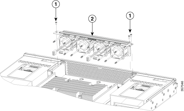
In the Cisco Catalyst 8500L-8S4X Edge Platform, there is a field replaceable unit (FRU) fan tray (see Figure 13) The fan tray includes all the fans in one assembly. If a fan fails, replace the tray using a #1 Phillips screwdriver.

Before Replacing a Fan Tray

Read the safety precautions below before replacing a fan tray:

  • Read the entire procedure and have the required tools available.

  • Power off the unit and disconnect all cables from the unit.

  • Remove the device from the equipment rack.

Replace the Fan Tray Cisco 8500L-8S4X

Remove the Fan Tray

To remove the fan tray, complete the following steps:

Procedure

Step 1

Remove the top cover. See Remove the Chassis Cover.

Step 2

Remove the three screws that secure the fan tray to the chassis.

Step 3

Disconnect fan cables from the motherboard.

Step 4

Remove the fan tray.

Figure 21. Fan Tray

1

Screws

2

Fan Tray


Install the Fan Tray

The C8500L-8S4X supports forward air flow (standard version). To install the fan tray, complete the following steps :

Procedure

Step 1

Install the fan tray.

Step 2

Install the three fan tray mounting screws.

Step 3

Connect the fan cables to the motherboard.

Note


The fan number (FAN0, FAN1, FAN2, and FAN3) is marked on the top of the fan tray and the motherboard. The fan wire should be connectedto its corresponding connector on the motherboard.

Step 4

Install the top cover

Step 5

Re-install the unit back in an equipment rack.

Step 6

Reinstall all cables from the chassis

Step 7

Power on the unit.


Install SFP and SFP+ Modules

Before you begin

See the Cisco Catalyst 8500L-8S4X Edge Platform's datasheet on cisco.com for a list of supported SFP and SFP+ modules. Use only supported SFP/SFP+ modules on the platform.


Warning


Class 1 laser product. Statement 1008
  • Do not remove the dust plugs from the SFP and SFP+ modules or the rubber caps from the fiber-optic cable until you are ready to connect the cable. The plugs and caps protect the module ports and cables from contamination and ambient light.

  • Removing and installing an SFP and SFP+ module can shorten its useful life. Do not remove and insert any SFP/SFP+ module more often than is necessary.

  • To prevent ESD damage, follow your normal board and component handling procedures when connecting cables to the switch and other devices.

  • When you insert several SFP and SFP+ modules in multiple ports, wait for 5 seconds between inserting each SFP/SFP+. This will prevent the ports from going into error disabled mode. Similarly, when you remove an SFP and SFP+ from a port, wait for 5 seconds before reinserting it.

Procedure


Step 1

Attach an ESD-preventive wrist strap to your wrist and to an earth ground surface.

Step 2

Find the send (TX) and receive (RX) markings that identify the top of the SFP/SFP+ module.

On some SFP/SFP+ modules, the send and receive (TX and RX) markings might be shown by arrows that show the direction of the connection.

Step 3

If the SFP/SFP+ module has a bale-clasp latch, move it to the open, unlocked position.

Step 4

Align the module in front of the slot opening, and push until you feel the connector snap into place.

Step 5

If the module has a bale-clasp latch, close it to lock the SFP/SFP+ module in place.

Step 6

Remove the SFP and SFP+ dust plugs and save.

Step 7

Connect the SFP and SFP+ cables.


Laser Safety Guidelines

Optical Small-Form Pluggable (SFPs) use a small laser to generate the fiber-optic signal. Keep the optical transmit and receive ports covered whenever a cable is not connected to the port.


Warning


Invisible laser radiation may be emitted from disconnected fibers or connectors. Do not stare into beams or view directly with optical instruments. Statement 1051

Warning


Ultimate disposal of this product should be handled according to all national laws and regulations. Statement 1040

Warning


Pluggable optical modules comply with IEC 60825-1 Ed. 3 and 21 CFR 1040.10 and 1040.11 with or without exception for conformance with IEC 60825-1 Ed. 3 as described in Laser Notice No. 56, dated May 8, 2019. Statement 1255.

Follow these steps to install an SFP module in your router:

Procedure


Step 1

Read the Safety Warnings section and disconnect the power supply before you perform any module replacement.

Step 2

Slide the SFP into the router connector until it locks into position

Tip


If the SFP uses a bale-clasp latch (see Laser Safety Guidelines section, the handle should be on top of the SFP module.

Caution


Do not remove the optical port plugs from the SFP until you are ready to connect cabling.

Step 3

Connect the network cable to the SFP module.


Remove Small Form-Factor Pluggable Modules

Follow these steps to remove a Small Form-Factor Pluggable (SFP) from the device:

Procedure


Step 1

Read the Safety Warnings section and disconnect the power supply before you perform any module replacement.

Step 2

Disconnect all cables from the SFP.

Warning

 
Invisible laser radiation may be emitted from disconnected fibers or connectors. Do not stare into beams or view directly with optical instruments. Statement 1051

Caution

 
The latching mechanism used on many SFPs locks the SFP into place when cables are connected. Do not pull on the cabling in an attempt to remove the SFP.

Step 3

Disconnect the SFP latch.

Note

 
SFP modules use various latch designs to secure the module in the SFP port. Latch designs are not linked to SFP model or technology type. For information on the SFP technology type and model, see the label on the side of the SFP.
Figure 22. Disconnecting SFP Latch Mechanisms

1

Sliding latch

3

Bale-clasp latch

2

Swing and slide latch

4

Plastic collar latch

Tip


Use a pen, screwdriver, or other small straight tool to gently release a bale-clasp handle if you cannot reach it with your fingers.

Step 4

Grasp the SFP on both sides and remove it from the device.


Remove and Install an M.2 Module

This section describes installing and replacing an an M.2 module on the Cisco Catalyst 8500L-8S4X Edge Platform.

Prevent Electrostatic Discharge Damage

The M.2 module is sensitive to electrostatic discharge (ESD) damage, which can occur when electronic cards or components are handled improperly. ESD results in complete or intermittent failures.

To prevent ESD damage, follow these guidelines:

  • Always use an ESD wrist or ankle strap and ensure that it makes good skin contact.

  • Connect the equipment end of the strap to an unfinished chassis surface.

  • Place the M.2 storage devices on an anti-static surface or in a static shielding bag. If you have to return the device to the factory, immediately place it in a static shielding bag.

  • Avoid contact between the device and clothing. The wrist strap protects the device from ESD voltages on the body only; ESD voltages on clothing can still cause damage.

  • Do not remove the wrist strap until the installation is complete.


Caution


For safety, periodically check the resistance value of the anti static strap. The measurement should be between 1 and 10 megohms (Mohms).

Install and Remove the M.2 Storage Device

To install and remove a M.2 storage device, perform the following steps:

Procedure


Step 1

Disconnect the power supply to the C8500L-8S4X before you perform any module replacement.

Step 2

Loosen the two mounting screws using a #1 Phillips screwdriver and then remove the M.2 module or blank.

Step 3

Install the M.2 memory module into the slot.

Figure 23. Remove the M.2 Storage Device

1

M.2 Module

2

M.2 blank

3

Mounting screws.

4 Chassis cutout (key to prevent installation of M.2 with incorrect orientation)

Note


When the M.2 module is not installed, install a blank in the slot.

Step 4

Secure the 2 mounting screws using a #1 Phillips screwdriver. Torque to 4-6 in-lbs.