CP Geographical Redundancy

Feature Summary

Table 1. Summary Data

Applicable Product(s) or Functional Area

cnBNG

Applicable Platform(s)

SMI

Feature Default Setting

Disabled – Configuration Required

Related Changes in this Release

First Release

Related Documentation

Not Applicable

Revision History

Table 2. Revision History
Revision Details Release

Introduced Geo Redundancy support for AIO Control Plane Cluster.

2024.03.0

Introduced Traffic Monitoring functionality for CP-GR sites.

2024.03.0

Introduced support for cnBNG to prepend the AS-path attribute to BGP Virtual IP (VIP) routes.

2024.02.0

Introduced support for BGP IPv6 route advertisement and IPv6 neighbor peering.

2024.02.0

First introduced.

2024.01.0

Feature Description

CP Geographical redundancy provides protection to the cnBNG Control Plane site against service failures that occur due to natural disasters or massive system outages such as power failures. CP Geo redundancy takes place through replication of sessions, and any other data required for seamless failover and failback of services to the remote site.


Note


CP Geo redundancy feature is supported only for IPoE sessions.


Prerequisites for CP-GR Cluster Bring Up

The following are prerequisites for bringing up the CP-GR cluster:

  • You can use either Cluster Manager (CM) or Inception server to bring up CP-GR K8s cluster.

  • The CIMC subnet of servers must be reachable from Inception or CM.

  • The management VLAN can use /28 or /24 subnet masks on Modular LAN On Motherboard (MLOM) bond.

  • The customer network can use /29 subnet mask on PCIe bond.

  • You can use the number of servers depending on the scale requirements. You need a minimum of three servers per site for the CP-GR cluster to achieve both cluster and local level redundancy.

  • You can use a firewall based on your deployment requirement.

  • You can use UCS C220M6 or M7SX servers.

Port Connections per CP-GR Site

The following diagram illustrates the port connections per CP-GR site.

Figure 1. Port Connectivity per CP-GR Site

Physical Connections per CP-GR Site

The following diagram illustrates the physical connections per CP-GR site.

Figure 2. Physical Connections per CP-GR Site

CP-GR Network Slicing Requirements

The following are the CP-GR network slicing requirements:

  • You can use VLANs as per your network requirements.

  • You can use the same or different VLANs between CP-GR sites.

  • VLANs and addresses such as cdl vips, udp vips, and inittcp vips must be reachable from the other site of CP-GR cluster.

  • You can use VLANs on different port bundles as mentioned in the following network slicing example.

Sample Network Slicing Details - Site 1

Site 1
Type Description Node Physical Interface Logical Interface VLAN Physical IP Vip IP if any
BGP bgp between proto1 and leaf1 server-1 proto1/svr1 enp94s0f0 enp94s0f0.151 151 10.1.1510.1/29 N.A
bgp between proto1 and leaf2 server-1 proto1/svr1 enp216s0f0 enp216s0f0.152 152 10.1.152.1/29 N.A
bgp between proto2 and leaf1 server-2 proto2/svr4 enp94s0f0 enp94s0f0.151 151 10.1.151.2/29 N.A
bgp between proto2 and leaf2 server-2 proto2/svr4 enp216s0f0 enp216s0f0.152 152 10.1.152.2/29 N.A
N4 External VIP N4 VIP. External VIP proto1/svr1 bd2 bd2.n4.161 161 10.1.1610.1/29 N4 Site 1 - 209.165.200.1/32 N4 Site 209.165.200.22/32 You can use different addresses
proto2/sv4 bd2 bd2.n4.161 161 10.10.161.2/29
N4 Internal VIP N4 Internal VIP proto1/svr1 bd2 bd2.intudp.163 163 10.1.163.1/29 10.1.163.100/32
proto2/svr4 bd2 bd2.intudp.163 163 10.1.163.2/29
Geo Geo Internal and External VIP. Grouping required for both proto1/svr1 bd1 bd1.inttcp.164 164 10.1.164.1/29 Internal: 10.1.164.100/32 Ext: 10.1.164.101/32 You can use different addresses
proto2/svr4 bd1 bd1.inttcp.164 164 10.1.164.2/29
CDL CDL services svr-2 bd1 bd1.cdl.165 165 10.1.165.1/29 CDL: 10.1.165.100, Kafka1: 10.1.165.101, Kafka2: 10.1.165.102. You can use different addresses
svr-3 bd1 bd1.cdl.165 165 10.1.165.2/29
K8s mgmt K8s Management IP address VLAN 125 Primary1 eno5 & eno6 bd0.k8s.125 125 10.100.3.1/28 10.1.125.10/28 gw- 10.1.125.101 You can use different addresses
Primary2 eno5 & eno6 bd0.k8s.125 125 10.100.3.2/28
Primary3 eno5 & eno6 bd0.k8s.125 125 10.100.3.3/28
worker1 eno5 & eno6 bd0.k8s.125 125 10.100.3.4/28
mgmt Management IP address Primary1 eno5 & eno6 bd0.mgmt.325 325 10.100.2.11/28 10.100.2.10/24 You can use different addresses
Primary2 eno5 & eno6 bd0.mgmt.325 325 10.100.2.12/28
Primary3 eno5 & eno6 bd0.mgmt.325 325 10.100.2.13/28
worker1 eno5 & eno6 bd0.mgmt.325 325 10.100.2.14/28

Sample Network Slicing Details - Site 2

Site-2
Type Description Node Physical Interface Logical Interface VLAN Physical IP Vip IP if any
BGP bgp between proto1 and leaf1 server-1 proto1/svr1 enp94s0f0 enp94s0f0.151 151 10.2.151.1/29 N.A
bgp between proto1 and leaf2 server-1 proto1/svr1 enp216s0f0 enp216s0f0.152 152 10.2.152.1/29 N.A
bgp between proto2 and leaf1 server-2 proto2/svr4 enp94s0f0 enp94s0f0.151 151 10.2.151.2/29 N.A
bgp between proto2 and leaf2 server-2 proto2/svr4 enp216s0f0 enp216s0f0.152 152 10.2.1510.2/29 N.A
N4 External VIP N4 VIP. External VIP proto1/svr1 bd2 bd2.n4.161 161 10.2.161.1/29 N4 Site 1- 209.165.200.1/32 N4 Site 2- 209.165.200.22/32
proto2/sv4 bd2 bd2.n4.161 161 10.2.161.2/29
N4 Internal VIP N4 Internal VIP proto1/svr1 bd2 bd2.intudp.163 163 10.2.163.1/29 10.2.163.200/32
proto2/svr4 bd2 bd2.intudp.163 163 10.2.163.2/29
Geo Geo Internal and External VIP. Grouping required for both proto1/svr1 bd1 bd1.inttcp.164 164 10.2.164.1/29 Internal: 10.2.164.200 Ext: 10.2.164.201
proto2/svr4 bd1 bd1.inttcp.164 164 10.2.164.2/29
CDL CDL services svr-2 bd1 bd1.cdl.165 165 10.2.165.1/29 CDL: 10.2.165.200, Kafka1: 10.2.165.201, Kafka2: 10.2.165.202
svr-3 bd1 bd1.cdl.165 165 10.2.165.2/29
K8s Management K8s Management IP address VLAN 125 Primary1 eno5 & eno6 bd0.k8s.125 125 10.200.3.1/28 10.2.126.10/28 gw-10.2.126.101 You can use different addresses
Primary2 eno5 & eno6 bd0.k8s.125 125 10.200.3.2/28
Primary3 eno5 & eno6 bd0.k8s.125 125 10.200.3.3/28
worker1 eno5 & eno6 bd0.k8s.125 125 10.200.3.4/28
Management Management IP address Primary1 eno5 & eno6 bd0.mgmt.325 325 10.100.2.14/28 10.100.2.20/24 You can use different addresses
Primary2 eno5 & eno6 bd0.mgmt.325 325 10.100.2.15/28
Primary3 eno5 & eno6 bd0.mgmt.325 325 10.100.2.16/28
worker1 eno5 & eno6 bd0.k8s.125 325 10.100.2.16/28

Architecture

The following figure shows two sites with cnBNG cluster that is connected to the spine-leaf BGP core network.

Figure 3. cnBNG CP Geo Redundancy Architecture

Each cnBNG cluster runs BGP and Geo redundancy pods on Protocol node. The protocol node provides high availability using active-standby topology.

BGP speaker pod runs on protocol node where the BGP routing protocol is hosted. It also runs BFD protocol for detecting BGP link failures.

The following sequence of steps set up the BGP speaker pods:

  • The BGP speaker pods use TCP as the transport protocol, on port 179. These pods use the AS number that is configured in the Ops Center CLI.

  • Connection is established with all the BGP peers provided by the Ops Center CLI.

  • All VIP IP addresses of endpoints, which are configured in the Ops Center CLI are published.

  • The import policies for routing are configured using CLI configuration.

  • Similar to the cache pod, two BGP speaker pods run on each Namespace as Active-Active.

Active-Active GR Deployment

The following figure illustrates the dynamic routing of Active-Active GR deployment, consisting of site A and site B.

Figure 4. Site A

The Service IP address 209.165.201.1 is configured on both the nodes 209.165.202.129 and 209.165.202.130. POD1 is running on host 209.165.202.129 and POD2 on 209.165.202.130. The host IP address exposes the pod services. BGP speaker publishes the route 209.165.201.1 through 209.165.202.129 and 209.165.202.130. It also publishes the MED values 1210 and 1220 to determine the priority of pods.

Figure 5. Site B

MED Value

The Local Preference is used only for IGP neighbours, whereas the Multi Exit Discriminator (MED) Attribute is used only for EGP neighbours. A lower MED value is the preferred choice for BGP.

Table 3. For Primary Role:
Bonding Interface Active VIP Present MED Value Local Preference
Yes Yes 1210 2220
Yes No 1220 2210
No Yes 1215 2215
No No 1225 2205
Table 4. For Standby Role:
Bonding interface active VIP present MED value

Local Preference

Yes Yes 2210 1220
Yes No 2220 1210
No Yes 2215 1215
No No 2225 1205
Table 5. For Non Primary/Standby Role:
Bonding interface active VIP present MED value

Local Preference

NA NA 3220 220

BGP Speaker POD periodically checks the VIP status, and Active interface of bonded interface on Protocol node. If a change is detected, then the BGP re-advertises routes based on the VIP/bonded interface state.

Geo Redundancy Support for AIO Control Plane Cluster

Table 6. Feature History

Feature Name

Release Information

Description

Geo Redundancy Support for AIO Control Plane Cluster 2024.03.0

This feature provides higher service availability using Geographical Redundancy for cnBNG all-in-one (AIO) Control Plane clusters, reducing the risk of outages.

CP-GR feature, previously available for 3-server and 4-server clusters, has been expanded to include AIO clusters.

The implementation of Geographical redundancy on AIO control plane clusters allows for continuous operation even if one AIO Control Plane cluster experiences a failure, maintaining uninterrupted services.

Architecture

This figure shows two sites with cnBNG AIO Control Plane cluster that is connected to the spine-leaf BGP core network.

Figure 6. AIO CP Geo Redundancy Architecture

Each AIO cluster runs a single instance of BGP-Speaker pod and Geo-Replication pod.

You can use a single server to achieve GR functionality on an AIO CP cluster.

The BGP-Speaker pod is equipped with BGP routing protocol and BFD protocol, providing rapid BGP link failure detection to maintain uninterrupted network connectivity. It establishes secure connections with all BGP peers as per the user-defined configuration, fostering a reliable routing environment.

Furthermore, the BGP-Speaker pod dynamically publishes IPv4 and IPv6 Virtual IP addresses (VIPs) of endpoints, facilitating efficient network traffic management. It also imports and enforces routing policies based on the configuration settings.

CP-GR Switchover Scenarios

The scenarios that can trigger CP-GR switchover on an AIO cluster are:

  • Pod monitoring failure

  • BGP/BFD monitoring failure

  • POD restart of bgpspeaker-pod

  • POD restart of georeplication-pod

  • Traffic monitoring failure, and

  • Manual switchover using geo switch-role command.

Active-Active GR Deployment

The BGP speaker advertises Service IP addresses to manage incoming traffic from both the sites (site A and site B).

eBGP is configured between the AIO-site Control Plane and the Leaf switches, and iBGP is set up between Leaf1/2 and Spine switches. The use of Local Preference within iBGP neighbors allows for precise internal traffic prioritization, while the MED Attribute for eBGP neighbors dictates external routing preferences.

Routes advertised with a lower MED value are preferred in the BGP selection process, guiding traffic towards the most efficient path.

GR-Replication Pod

GR-replication pod performs the following functions:

  • Replicates ETCD and Cache pods data across sites.

  • Provides a communication channel between sites.

  • Maintains local instances roles of a site in ETCD.

  • Monitors local site status (pods status or BFD status or VIP status)

GR-replication pod works in a high availability (HA) setup to maintain the local instances roles of a site in ETCD. Monitoring (local and remote) is disabled in GR-Replication pod in a HA setup. When a site faces an issue, and fails to support the traffic handling at run-time, GR-replication pod internally detects the issue, and allows the standby site to handle the traffic with no or minimum impact.

GR-replication pod is a host networking pod, and it runs on actual worker IP address and not on IP address that is assigned internally by k8.

In a HA setup, one instance of GR-replication pod must be running, and activities related to GR setup such as pod monitoring, and VIP monitoring are not active.

In a GR setup:

  • Two instances of GR-replication pod must be running for each cluster. One instance of GR-replication pod is active, and another instance is standby.

  • Each GR-replication pod runs on a separate Proto node.

  • GR-replication pod requires dedicated VIPs.

    • Internal-VIP for inter-pod (within the same cluster) communication.

    • External-VIP for communication with other clusters.

  • The VIPs configured for GR-replication are active on one of the Proto nodes at a time. The GR-pod running on the same Proto node where the VIPs are active is marked as Active GR-replication pod, and the other GR-pod is marked as standby.

  • If the active GR-pod is stopped or crashed during runtime, VIP (internal and external) switches to other Proto node, and the standby GR pod becomes Active. The switching of VIP from one Proto node to another Proto node is handled by Keepalived process.

  • GR-replication pod uses base port as 15000 (default) + 4 for keepalived monitoring.

ETCD and Cache Pod Replication

Data from ETCD and Cache Pod are replicated to the remote site based on the following two categories:

  • Immediate sync

  • Deferred sync

Immediate Sync

Data that must be replicated immediately to the remote site belongs to the immediate sync category. Immediate sync data replication is a synchronous call, and replication failure on the remote site returns an error response. Data is replicated to the remote site only for instances whose role is PRIMARY.

Deferred Sync

Data that do not require immediate replication to the remote site belongs to the deferred sync category. This data is maintained in the in-memory cache in GR-replication pod. Data is replicated to the remote site only for instances whose role is PRIMARY.

Deferred sync happens periodically using background thread. Periodicity must be configured before deployment using the YAML file. By default, periodicity is set to 10s.

Deferred sync includes two processes that are executed in a single thread, which runs sequentially.

  • Deferred sync process: Local site data is pushed to the remote site.

  • Checkpointing process: Data of the instance whose role is PRIMARY on the remote site is pulled into the current site.

Pod Monitoring

You can configure each pod that need to be monitored. Based on the user configuration, GR-replication pod starts monitoring the pods and detects a pod failure. If the number of replica-sets failed for the pod is greater than the configured threshold, then the GR-replication pod switches over the Role to a mated pair. The current site moves to STANDBY_ERROR state indicating that the site has an issue and cannot serve the traffic.

The detection request timeout interval for the first request is set at 2s, and for subsequent request it is set at 1s. In worst-case scenario, the total time to detect a pod failure is approximately 5s to 6s, with the total convergence time between 7s to 9s.


Note


Pod monitoring on GR-replication pod starts after 15 minutes of its configuration.


Traffic Monitoring

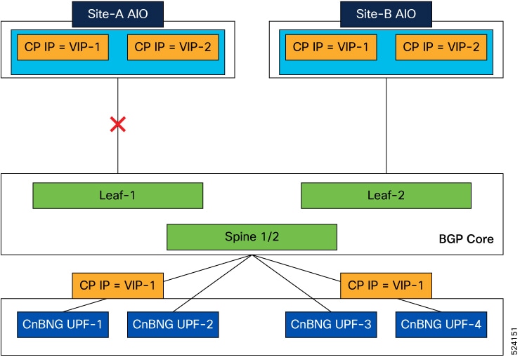
This figure illustrates the geo-redundant setup between AIO sites.

Figure 7. GR Setup for AIO Sites

Our network architecture introduces a geo-redundant setup between Site-A and Site-B, ensuring continuous service availability. Geo-Redundancy (GR) instance-1 operates actively on Site-A and remains on standby on Site-B, while GR instance-2 functions actively on Site-B with a standby role on Site-A.

In the event of a failure or connectivity loss at Site-A, the Leaf/Spine switches automatically withdraw the BGP routes associated with Site-A. This triggers the switches to reroute incoming traffic towards Site-B. The Traffic Monitoring feature on Site-B detects the surge in traffic and, upon reaching a predefined packet threshold, the GR-pod initiates a transition for GR Instance-1 from Standby to Active status.

Simultaneously, the BGP-Speaker pod on Site-B proactively readvertises the routes for the GR Instance-1 endpoint, assigning a lower MED value to prioritize these routes. This dynamic response ensures minimal service disruption and maintains optimal traffic flow.

Configure Traffic Monitoring

Use this configuration to enable traffic monitoring functionality.

config 
 geomonitor 
  trafficMonitor 
   thresholdCount value 
   thresholdInterval interval_value 
  exit 
 exit 

NOTES:

  • thresholdCount value : Specifies the number of calls received for the standby instance.

  • thresholdInterval interval_value : Specifies the maximum duration window to hit the threshold count value, in milliseconds.

The following is a sample configuration.

geomonitor trafficMonitor
thresholdCount 3
thresholdInterval 3000

Instance Roles

Each GR setup site contains multiple instances and roles.

  • PRIMARY: Site is ready and actively taking traffic for the given instance.

  • STANDBY: Site is standby, ready to take traffic but not taking traffic for the given instance.

  • STANDBY_ERROR: Site is in problem, not active and not ready to take traffic for the given instance.

  • FAILOVER_INIT: Site has started to failover and not in condition to take traffic. Buffer time is 2 sec for application to complete their activity.

  • FAILOVER_COMPLETE: Site has completed the failover and attempted to inform the peer site about the failover for given instance. Buffer time is 2 seconds.

  • FAILBACK_STARTED: Manual failover is triggered with delay from remote site for the given instance

For fresh installation, site boots up with:

  • Role PRIMARY for local instance (each site has local instance-id configured to identify local instance). It is recommended not to configure the pods for monitoring during fresh installation. Once the setup is ready, you can configure the pods for monitoring.

  • Role STANDBY for other instances.

For upgrades, site boots up with:

  • STANDBY_ERROR role for all the instances as moving the traffic post upgrade needs manual intervention.

  • ETCD stores instance roles.


Note


Rolling upgrade or in-service upgrade isn’t supported.


After SMI cluster upgrades, GR instance roles may come up as PRIMARY/PRIMARY at site-1, and STANDBY/STANDBY at site-2 sometimes. To make local GR-instance role as PRIMARY on the given site, you must trigger CP-GR switchover manually using the geo switch-role instance-id gr_instanceId command.

IPAM

The IP Address Management (IPAM) is a technique for tracking and managing the IP address space of a network.

IPAM stores operational data of active instances in Cache-POD. Cache-POD records are synced to respective standby-cluster of the instances.

During GR switchover of an instance, the new active instance restores IPAM data from the Cache-POD, and continues to allocate IPs for the instance.

The following figure illustrates the IPAM architecture:

Figure 8. IPAM Architecture
  • GR Instance-1 is the local instance of Site A and geo-paired with Site B.

  • GR Instance-2 is the local instance of Site B and geo-paired with Site A.

During normal operation, Site A handles UPF-association/release, address-allocation/release for subscribers coming up in GR-instance-1. IPAM writes GR Instance-1 specific content to Cache-POD in the Site A cluster. Then, the IPAM’s Cache-POD content is synced to the Site B's Cache-POD (geo-paired cluster).

Similarly, Site B handles UPF-association/release, address-allocation/release for subscribers coming up in GR-instance-2. IPAM writes GR Instance-2 specific content to Cache-POD in Site B cluster. Then, the IPAM’s Cache-POD content is synced to Site A Cache-POD (geo-paired cluster).

When one of the clusters goes-down, the respective geo-paired cluster restores the content from local Cache-POD. For example, If Site B goes down, Site A gets role-change trigger for GR Instance-2, and IPAM in Site A restores the content of GR Instance-2 from local Cache-POD (which was already synced). Also, IPAM in Site A handles UPF-register/release, and address-allocate/release for subscribers coming up with GR Instance-2 using the restored content.

IPAM uses both "immediate-sync" and "deferred-sync" options to sync Cache-POD content between clusters.

Limitations and Restrictions

The CP Geo Redundancy has the following limitations and restrictions in this release:

  • CP Geo Redundancy is not triggered if both the Geo pods are down or deleted. CP GR is triggered only after both the Geo pods are up.

  • Restarting Kafka in one site and Mirrormaker pod on the other site is not supported.

  • On system reboot, instances are not automatically associated with the right roles. You must set the roles correctly the first time.

  • IP address leaks can occur in IPAM. To address this issue, run the reconcile ipam CLI command.

  • Pod Monitoring is not supported for CDL pods and few App-infra pods.

  • Subscriber sessions can desynchronize between the CP and UP. The solution for this issue is to run CP to UP reconciliation for sessions between the CP and UP.

  • Node or pod restart can cause mismatch of session records between pods in the cluster. You must use CP audit to rectify this issue.

Configuring CP Geo-Redundancy

CP Geo-Redundancy configuration is classified into the following categories:

  • NF Configuration—This configuration is similar on all GR instances of the NF.

  • Cluster Instance Specific NF Configuration—This configuration contains cluster specific data, which differs on each GR instance of the NF.

Configuring NF Instance

Use the following configuration to configure the NF instance. Each NF instance is identified by a unique number.

config 
   instances instance instance_id 
   exit 

Example:

config
   instances instance 1
   exit
   instances instance 2
   exit

Local Instance ID Configuration

The local Instance is configured using the local-instance command.

local-instance instance instance_id 

Only two instances can be configured on each local and remote site, and corresponding endpoints can be instantiated.

A local instance-id is the identity of the local site irrespective of whether the site is GR aware.


Note


Changing the local instance while the system is running is not supported.


Configuring Endpoints

You must configure the endpoints under an instance specified by a unique instance ID.

Use the following configuration to configure endpoints:

config 
  instance instance-id gr_instanceId 
    endpoint radius  
      replicas replicas_count 
      nodes nodes_count 
      interface coa-nas  
        vip-ip vip_ipv4_address vip-port vip_port_number vip-interface interface_id 
         vip-ipv6 vip_ipv6_address vip-port vip_port_number vip-interface interface_id 
      exit 
    exit 
    endpoint udp-proxy  
      nodes nodes_count 
      internal-vip vip_ip_address 
      vip-ip vip_ipv4_address vip-port vip_port_number vip-interface interface_id 
      vip-ipv6 vip_ipv6_address vip-port vip_port_number vip-interface interface_id 
      interface n4  
        sla response seconds  
        vip-ip vip_ipv4_address vip-interface interface_name 
        vip-ipv6 vip_ipv6_address vip-interface interface_name 
      exit 
      interface gtpu  
        sla response milliseconds 
      exit 

NOTES:

  • instance instance-id gr_instanceId : Specifies the GR instance ID.

  • endpoint radius : Configures the parameters for the RADIUS endpoint and enters the endpoint sub-mode.

  • endpoint udp-proxy : Configures the parameters for the UDP-proxy endpoint and enters the endpoint sub-mode.

  • replicas replicas_count : Specifies the number of replicas per node. Must be an integer.

    In a GR setup for AIO CP cluster, the replica count must be 1 for BGP speaker pod, GR-replication pod, and UDP-proxy pod. For other pods, the replica count should be based on capacity planning.

  • nodes nodes_count : Specifies the number of nodes. Must be an integer.

  • interface coa-nas : Defines a new interface "coa-nas", and allows to enter the CoA NAS interface configuration mode.

  • interface n4 : Defines the N4 interface, and allows to enter the N4 interface configuration mode.

  • interface gtpu : Defines the GTPu interface, and allows to enter the GTPu interface configuration mode.

  • vip-ip vip_ipv4_address vip-port vip_port_number : Specifies the VIP IPv4 address, and VIP port number of the interface.

  • vip-ipv6 vip_ipv6_address vip-port vip_port_number : Specifies the VIP IPv6 address, and VIP port number of the interface.

  • vip-interface interface_id : Specifies the VIP interface name.

  • internal-vip vip_ip_address : Specifies the internal VIP IP address of the additional endpoint.

  • sla response response_time : Specifies the response time in milliseconds.

Examples:

endpoint radius
   replicas 1
   nodes 2
   memory limit 16384
   interface coa-nas
     sla response 140000
     vip-ip 209.72.100.1 vip-port 3799 vip-interface bd2.n4.162
   exit
exit
instance instance-id 1
   endpoint pfcp
      vip-ipv6 2001::1 vip-interface bd2.n4.2105
   interface n4
      vip-ipv6 2001::10 vip-interface bd2.n4.2602

Configuring Geo Replication

Endpoints must be configured under an instance. Two Geo-Redundancy pods are needed on each GR site. You should also configure VIP for internal and external Geo interface for ETCD/CachePod replication.

instance instance-id  instance_id endpoint geo interface { geo-internal | geo-external } { vip-ip  vip_ipv4_address | vip-ipv6 vip_ipv6_address } vip-port  vip_port_number 
 
config 
  instance instance-id instance_id 
   endpoint geo 
    replicas replicas_count 
    nodes node_count 
    interface geo-internal 
     vip-ip vip_ipv4_address vip-port vip_port_number 
     vip-ipv6 vip_ipv6_address vip-port vip_port_number 
    exit 
    interface geo-external 
     vip-ip vip_ipv4_address vip-port vip_port_number 
     vip-ipv6 vip_ipv6_address vip-port vip_port_number 
    exit 
  exit 
exit 

NOTES:

  • instance instance-id instance_id : Specifies the GR instance ID. One instance ID for local site and the other for remote site.

  • replicas replicas_count : Specifies the number of replicas per node. Must be an integer.

    In a GR setup for AIO CP cluster, the replica count for GR-replication pod must always be 1.

  • vip-ip vip_ip_address : Specifies the VIP IPv4 address for Internal/External Geo interface.

  • vip-ipv6 vip_ipv6_address : Specifies the VIP IPv6 address for Internal/External Geo interface.

  • vip-port vip_port_number : Specifies the VIP port number.

The following is a sample configuration:

instance instance-id 1
endpoint geo
  replicas 1
  nodes 2
  interface geo-internal
   vip-ip 209.165.201.8 vip-port 7001
  exit
  interface geo-external
   vip-ipv6 2001:DB8:1::1 vip-port 7002
  exit
exit

Configuring IPAM

You can configure all the IPAM parameters under an instance specified by a unique instance ID.

Configuring RADIUS

The following is a sample RADIUS configuration:

profile radius
 attribute
  nas-identifier CISCO-BNG-SITE-2
  instance 1
   nas-identifier CISCO-BNG-1
   nas-ip 209.165.100.1
  exit
  instance 2
   nas-identifier CISCO-BNG-2
   nas-ip 209.166.100.2
  exit
 exit
 accounting
  deadtime 3
  attribute
   instance 1
    nas-identifier cisco-acct-1
    nas-ip 209.165.100.1
   exit
   instance 2
    nas-identifier cisco-acct-2
    nas-ip 209.166.100.2
   exit
  exit
 exit

NOTES:

  • instance instance_id : Configures multiple instances for the specified instance and enters the instance sub-mode.

  • nas-identifier value : Specifies the attribute name by which the system will be identified in Accounting-Request messages. value must be an alphanumeric string.

  • nas-ip ipv4_address : Specifies the NAS IPv4 address. ipv4_address must be an IPv4 address in dotted decimal notation.

  • deadtime value : Sets the time to elapse between RADIUS server marked unreachable and when we can re-attempt to connect.

    value must be an integer from 0 through 65535. Default: 10 minutes.

Configuring Dynamic Routing using BGP

This section describes how to configure dynamic routing using BGP.

Configuring AS and BGP Router IP Address

To configure the AS and IP address for the BGP router, use the following commands:

config 
   router bgp local_as_number 
   exit 
exit 

NOTES:

  • router bgp local_as_number : Specifies the identification number for the local Autonomous Systems (AS).

    In a GR deployment, you need to configure two Autonomous Systems.

    • One AS for leaf and spine.

    • Second AS for both racks: Site-1 and Site-2

Configuring BGP Service Listening IP Address

To configure the BGP service listening IP address, use the following commands:

config 
   router bgp local_as_number 
      interface interface_name 
   exit 
exit 

NOTES:

  • interface interface_name : Specifies the name of the interface.

Configuring BGP Neighbors

To configure the BGP neighbors, use the following commands:

config 
   router bgp local_as_number 
      interface interface_name 
      neighbor neighbor_ip_address remote-as as_number 
   exit 
exit 

NOTES:

  • neighbor neighbor_ip_address : Specifies the IPv4/IPv6 address of the neighbor BGP router.

  • remote-as as_number : Specifies the identification number for the AS.

Configuring Bonding Interface

To configure the bonding interface related to the interfaces, use the following commands:

config 
   router bgp local_as_number 
      interface interface_name 
      bondingInterface interface_name 
   exit 
exit 

NOTES:

  • bondingInterface interface_name : Specifies the related bonding interface for an interface. If the bonding interface is active, then the BGP gives a higher preference to the interface-service by providing a lower MED value.

Configuring Learn Default Route

If you want to configure specific routes on your system and need to support all routes, then set the learnDefaultRoute value as true.


Note


This configuration is optional.


To configure the Learn Default Route, use the following commands:

config 
   router bgp local_as_number 
      learnDefaultRoute true/false 
   exit 
exit 

NOTES:

  • learnDefaultRoute true/false : Specifies the option to enable or disable the learnDefaultRoute parameter. When set to true, BGP learns default route and adds it in the kernel space. By default, it is false.

Configuring BGP Port

To configure the port number for a BGP service, use the following commands:

config 
   router bgp local_as_number 
      loopbackPort port_number 
   exit 
exit 

NOTES:

  • loopbackPort port_number : Specifies the port number for the BGP service. The default value is 179.

Policy Addition

The BGP speaker pods learns many route information from its neighbors. However, only a few of them are used for supporting the outgoing traffic. This is required for egress traffic handling only. Routes are filtered by configuring import policies on the BGP speakers and is used to send learned routes to the protocol pods.

A sample CLI code for policy addition and the corresponding descriptions for the parameters are shown below.

$bgp policy <policy_Name> ip-prefix 209.165.200.225/16 mask-range 21..24 as-path-set “^65100” interface bd2n.10 gateway 209.165.201.30
Table 7. Import Policies Parameters
Element Description Example Optional
as-path-set AS path value “^65100” Yes
ip-prefix Prefix value in format { IPv4_address/prefix length | IPv6_address/prefix length } “209.165.200.225/16” or "2001:DB8::1/32" Yes
mask-range IPv4 or IPv6 Mask range { 0..32 | 0..128 } “21..24” Yes
interface Interface to set as source IP (default is VM IP) eth0 Yes
gateWay IPv4/IPv6 Gateway address in either format { IPv4_address | IPv6_address } based on the type of ip-prefix value given 209.165.201.30 Yes
modifySourceIp Modify source IP of incoming route

Default value is False.

true Yes
isStaticRoute Flag to add static IP address into kernel route

Default value is False.

true Yes

AS-Path Prepending for BGP VIP Routes

Table 8. Feature History

Feature Name

Release Information

Description

AS-Path Prepending for BGP VIP Routes

2024.02.0

This feature allows the cnBNG to prepend the AS-path attribute to BGP Virtual IP (VIP) routes when advertising to neighboring routers. By manipulating the AS-path length, cnBNG influences the route preference on the border leaf routers, which programs the BGP routes into the network.

With this feature, you can ensure that the correct routing path is selected in a multi-VRF or multi-AS deployment scenario.

AS-Path Prepending for BGP VIP Routes feature enhances the CP-GR functionality in environments where multiple cnBNG clusters are configured across different Virtual Routing and Forwarding instances (VRFs) or Autonomous Systems (ASes).

cnBNG prepends its own AS number to the AS-path of BGP VIP routes before advertising them to BGP neighbors. This action effectively increases the AS-path length, making these routes less preferable compared to other routes with shorter AS-paths under normal BGP path selection criteria. The border leaf routers use this AS-path length information to determine the best route to the VIP, ensuring that traffic is routed through the appropriate cnBNG cluster.

Example Configuration

The following is a sample configuration to enable prepending AS-path attribute for BGP routes.

router bgp 65000 
   prepend as-path true  

Configuring BGP Speaker

This configuration controls the number of BGP speaker pods in deployment. BGP speaker advertises service IP information for incoming traffic from both the sites.


Note


  • Use non-bonded interface in BGP speaker pods for BGP peering.

  • BGP peering per Proto node is supported with only two BGP routers/leafs. Considering two Proto nodes, there can be a maximum of four BGP neighborships.

  • In a GR setup for AIO CP cluster, the replica count for BGP speaker pods must always be 1.


config 
  instance instance-id instance_id 
   endpoint bgpspeaker 
     replicas replicas_count 
     nodes node_count 
   exit 

The following is a sample configuration:

config
  instance instance-id 1
    endpoint bgpspeaker
     replicas 1
     nodes    2
    exit

Configuring BFD

Bidirectional Forwarding Detection (BFD) protocol is used for Faster Network Failure Detection along with BGP. Whenever connectivity between BGP peering fails with cluster (NF), failover is triggered to minimize traffic failure impact.

config 
  router bgp as 
    bfd interval interval min_rx min_rx multiplier multiplier 
    loopbackPort loopbackPort loopbackBFDPort loopbackBFDPort 
  interface interface_id  (BGP on non-bonded interface <-- loopbackEth)
    bondingInterface bondingInterface  (leaf6-nic)
    bondingInterface bondingInterface  (leaf6-nic)
    neighbor neighbor_ip_address remote-as remote_as fail-over fail_over_type 
  exit 
  interface interface_id  (BGP on non-bonded interface <-- loopbackEth)
    bondingInterface bondingInterface  (leaf7-nic)
    bondingInterface bondingInterface  (leaf7-nic)
    neighbor bondingInterface remote-as remote_as fail-over fail_over_type 
  exit 
  policy-name policy_name  
   as-path-set as_path_set 
   gateWay gateWay_address 
   interface interface_id_source 
   ip-prefix ip_prefix_value 
   isStaticRoute false | true 
   mask-range mask_range 
   modifySourceIp false | true 
  exit 
exit 

NOTES:

  • bgp as : Specifies the Autonomous System (AS) path set.

  • bfd : Specifies BFD configuration.

    • interval interval : Specifies the BFD interval in milliseconds.

    • min_rx min_rx : Specifies the BFD minimum RX in milliseconds.

    • multiplier multiplier : Specifies the BFD interval multiplier.

  • interface interface_id : Specifies BGP local interface.

    • bondingInterface bondingInterface : Specifies the linked bonding interface.

    • neighbor neighbor_ip_address : Specifies the IPv4/IPv6 address of neighbor.

      • fail-over fail_over_type : Specifies the failover type.

      • remote-as remote_as : Specifies the Autonomous System (AS) number of BGP neighbor.

  • learnDefaultRoute : Learns default route and adds it in kernel space

  • loopbackBFDPort loopbackBFDPort : Specifies the BFD local port.

  • loopbackPort loopbackPort : Specifies the BGP local port.

  • policy-name policy_name : Specifies the policy name.

    • as-path-set as_path_set : Specifies the Autonomous System (AS) path set.

    • gateWay gateWay_address : Specifies the gateway address.

    • interface interface_id_source : Specifies the interface to set as source IP.

    • ip-prefix ip_prefix_value : Specifies the IP prefix value.

    • isStaticRoute false | true : Specifies whether to add static route in kernel space. Default value is false.

    • mask-range mask_range : Specifies the mask range.

    • modifySourceIp false | true : Modifies the source IP of the incoming route. Default value is false.

      true: This option is used for non-UDP related VIPs. Source IP of the given interface is used as Source IP while sending out packets from cnSGW-C.

      false: This option is used for all UDP related VIPs. VIP is used as Source IP while sending out packets from cnSGW-C.

The following is a sample configuration:

         
router bgp 65142
 learnDefaultRoute false
 bfd interval 250000 min_rx 250000 multiplier 3
 interface enp94s0f0.3921
  bondingInterface enp216s0f0
  bondingInterface enp94s0f0
  neighbor 209.165.201.24 remote-as 65141 fail-over bfd
 exit
 interface enp94s0f1.3922
  bondingInterface enp216s0f1
  bondingInterface enp94s0f1
  neighbor 2001::250 remote-as 65141 fail-over bfd

Configuring POD Monitoring

To configure POD monitoring and failover thresholds in the GR setup, use the following configuration. The GR pod monitors the configured POD name.

config 
 geomonitor 
  podmonitor pods pod_name 
   retryCount value 
   retryInterval interval_value 
   retryFailOverInterval failover_interval 
   failedReplicaPercent percent_value 
  exit 
 exit 

NOTES:

  • pods pod_name : Specifies the name of the pod to be monitored. For example, Cache-pod, res-ep, and so on.

  • retryCount value : Specifies the retry counter value to retry if the pod fails to ping. After that the pod is marked as down. Must be an integer in the range of 1-10.

  • retryInterval interval_value : Specifies the retry interval in milliseconds if the pod successfully pings. Must be an integer in the range of 200-10000.

  • retryFailOverInterval failover_interval : Specifies the retry interval in milliseconds if the pod fails to ping. Must be an integer in the range of 200-10000.

  • failedReplicaPercent percent_value : Specifies the percent value of failed replica after which GR failover is triggered. Must be an integer in the range of 10-100.

The following is a sample configuration.

geomonitor podmonitor pods cache-pod
 retryCount 3
 retryInterval 5
 retryFailOverInterval 1
 failedReplicaPercent 40
exit

Configuring CDL Instance Awareness and Replication

In Common Data Layer (CDL), along with existing GR related parameters, GR instance awareness must be enabled using a feature flag on all sites. Also, the mapping of system-id to slice names should also be provided for this feature to work on all sites.

The CDL is also equipped with Geo Replication (GR) failover notifications, which can notify the timer expiry of session data and bulk notifications to the currently active site. The CDL uses Border Gateway Protocol (BGP) through App-Infra for the GR failover notifications.

The CDL subscribes to the key value on both the GR sites. The App-Infra sends notifications to the CDL when there is any change in these key values. A key value indicates the state of the CDL System ID or the GR instance. The GR instance is mapped to the CDL slices using the CDL system ID or the GR instance ID in the key.

The system ID is mandatory on both the sites. The GR instance ID in the NF configuration must match the CDL system ID.

CDL has instance-specific data slices. It also allows users to configure instance-specific slice information at the time of bringing up.

  • CDL notifies the data on expiry or upon bulk notification request from the active slices.

  • CDL determines the active instance based on the notification from app-infra memory-cache.

  • CDL slice is a partition within a CDL instance to store a different kind of data. In this case, NF stores a different instance of data.


Note


CDL slice name should match with the slice-name configured in GR.


Configuring CDL Instance Awareness

The following command is used to configure CDL instance awareness.

config 
cdl 
 datastore datastore_session_name 
   features 
     instance-aware-notification 
       enable [ true | false ] 
       system-id system_id 
        slice-names slice_names 
    end 

NOTES:

  • datastore datastore_session_name : Specifies the datastore name.

  • enable [ true | false ] : Enables the GR instance state check for slices.

  • system-id system_id : Maps the system ID to slice name.

  • slice-names slice_names : Specifies the list of slice names associated with the system ID. CDL slice name should match with the slice-name configured in GR.

The following is a sample configuration:

cdl datastore session
 features instance-aware-notification enable true
 features instance-aware-notification system-id 1
  slice-names [ sgw1 smf1 ]
 exit
 features instance-aware-notification system-id 2
  slice-names [ sgw2 smf2 ]
 end

Configuring CDL Replication

This section describes the CDL replication configuration.

  1. Configure Site-1 CDL HA system without any Geo-HA-related configuration parameters.

    1. Set the System ID as 1 in the configuration.

    2. Set the slot map/replica and index map/replica and Kafka replica as per the requirements.

    The following is a sample configuration:

    cdl system-id 1 
    cdl node-type session 
    cdl datastore session 
    endpoint replica replica_id 
      slot map 4 
      slot replica 2 
      index map 1 
      index replica 2 
    cdl kafka replica 2 
    
  1. Configure external IPs on Site-1 for Site-2 to Site-1 communication.

    1. Enable geo-replication on Site-1 and configure the remote Site as 2 for Site-1.

      cdl enable-geo-replication true
    2. Configure the external IP for CDL endpoint to be accessed by Site-2.

      cdl datastore session endpoint external-ip site-1_external_ip
    3. Configure the external IP and port for all Kafka replicas.

      So, if two replicas (default) are configured for Kafka, user need to provide two different <ip>+<port> pairs.

      cdl kafka external-ip site-1_external_ip port1 cdl kafka external-ip site-1_external_ip port2 
  2. Add remote site (Site-1) information on Site-2.

    • Remote site cdl-ep configuration on Site-2:

      cdl remote-site 1 db-endpoint host site-1_cdl_ep_ip

      cdl remote-site 1 db-endpoint port site-1_cdl_ep_port

      (Port Example: 8882)

    • Remote site Kafka configuration on Site-2:

      cdl remote-site 1 kafka-server site-1_kafka1_ip site-1_kafka1_port

      cdl remote-site 1 kafka-server site-1_kafka2_ip site-1_kafka2_port

    • Direct the session datastore configuration to remote Site-2 configuration:

      cdl datastore session geo-remote-site 1

    • (Optional) Configure the SSL certificates to establish a secure connection with remote site on Site-1. All the certificates are in multi-line raw text format. If the certificates are not valid, the server continues with non-secure connection.

      cdl ssl-config certs site-2_external_ip ssl-key <ssl_key>

      cdl ssl-config certs site-2_external_ip ssl-crt <ssl_crt>

  3. Commit GR configuration on Site-2:

    • Commit the configuration and let the pods be deployed on Site-2.

    • Verify all pods are in running state.

    • Once both sites are deployed, verify that the mirror maker pods on both sites are running and in ready state.

Examples

HA:

cdl node-type db-ims

cdl datastore session
 endpoint replica 2
 index map    1
 index write-factor 1
 slot replica 2
 slot map     4
exit

k8 label cdl-layer key smi.cisco.com/node-type value oam

Site-1:

cdl system-id          1
cdl node-type          session
cdl enable-geo-replication true

cdl remote-site 2
 db-endpoint host 209.165.201.21 >> Site-2 external CDL IP
 db-endpoint port 8882
 kafka-server 209.165.201.21 10092 >> Site-2 external CDL IP
 exit
exit

cdl label-config session
 endpoint key smi.cisco.com/node-type1
 endpoint value cdl-node
 slot map 1
  key   smi.cisco.com/node-type1
  value cdl-node
 exit
 index map 1
  key   smi.cisco.com/node-type1
  value cdl-node
 exit
exit
cdl logging default-log-level debug

cdl datastore session
 label-config    session
 geo-remote-site [ 2 ]
 slice-names     [ 1 2 ]
 endpoint cpu-request 100
 endpoint replica 2
 endpoint external-ip 209.165.201.25 >> Site-1 external CDL IP
 endpoint external-port 8882
 index cpu-request 100
 index replica 2
 index map   1
 slot cpu-request 100
 slot replica 2
 slot map    1
exit

cdl kafka replica 1
cdl kafka label-config key smi.cisco.com/node-type1
cdl kafka label-config value cdl-node
cdl kafka external-ip 209.165.201.25 10092 >> Site-1 external CDL IP

Site-2:

cdl system-id          2
cdl node-type          session
cdl enable-geo-replication true

cdl remote-site 1
 db-endpoint host 209.165.201.25 >> Site-1 external CDL IP
 db-endpoint port 8882
 kafka-server 209.165.201.25 10092 >> Site-1 external CDL IP
 exit
exit

cdl label-config session
 endpoint key smi.cisco.com/node-type12
 endpoint value cdl-node
 slot map 1
  key   smi.cisco.com/node-type12
  value cdl-node
 exit
 index map 1
  key   smi.cisco.com/node-type12
  value cdl-node
 exit
exit

cdl datastore session
 label-config    session
 geo-remote-site [ 1 ]
 slice-names     [ 1 2 ]
 endpoint cpu-request 100
 endpoint replica 2
 endpoint external-ip 209.165.201.21 >> Site-2 external CDL IP
 endpoint external-port 8882
 index cpu-request 100
 index replica 2
 index map   1
 slot cpu-request 100
 slot replica 2
 slot map    1
exit

cdl kafka replica 1
cdl kafka label-config key smi.cisco.com/node-type12
cdl kafka label-config value cdl-node
cdl kafka external-ip 209.165.201.21 10092 >> Site-2 external CDL IP

CP-GR for AIO - Configuration Example

This is a sample configuration to bring up CP-GR for AIO cluster.


instance instance-id 1
 endpoint geo
  replicas 1
  interface geo-internal
   vip-ip 3.3.174.3 vip-port 7001
   vip-ipv6 2002:4888:3:3::174:3 vip-ipv6-port 7001
  exit
  interface geo-external
   vip-ip 3.3.174.4 vip-port 7002
   vip-ipv6 2002:4888:3:3::174:4 vip-ipv6-port 7002
  exit
 exit
 endpoint bgpspeaker
  replicas 1
 exit
 endpoint sm
  replicas 2
 exit
 endpoint nodemgr
  replicas 2
 exit
 endpoint n4-protocol
  replicas 2
  retransmission max-retry 1
 exit
 endpoint dhcp
  replicas 2
 exit
 endpoint radius
  replicas 2
  interface coa-nas
   sla response 140000
   vip-ip 3.4.100.1 vip-port 3799 vip-interface bd2.n4.172
   vip-ipv6 2002:4888:3:4::100:1 vip-ipv6-port 3799 vip-interface bd2.n4.172
  exit
 exit
 endpoint udp-proxy
  replicas 1
  vip-ip 3.4.100.1 vip-interface bd2.n4.172
  vip-ipv6 2002:4888:3:4::100:1 vip-interface bd2.n4.172
  interface n4
   sla response 140000
  exit
  interface gtpu
   sla response 180000
  exit
 exit
exit
instance instance-id 2
 endpoint geo
  replicas 1
  interface geo-internal
   vip-ip 4.4.184.3 vip-port 7001
   vip-ipv6 2002:4888:4:4::184:3 vip-ipv6-port 7001
  exit
  interface geo-external
   vip-ip 4.4.184.4 vip-port 7002
   vip-ipv6 2002:4888:4:4::184:4 vip-ipv6-port 7002
  exit
 exit
 endpoint bgpspeaker
  replicas 1
 exit
 endpoint sm
  replicas 2
 exit
 endpoint nodemgr
  replicas 2
 exit
 endpoint n4-protocol
  replicas 2
  retransmission max-retry 1
 exit
 endpoint dhcp
  replicas 2
 exit
 endpoint radius
  replicas 2
  interface coa-nas
   sla response 140000
   vip-ip 4.3.100.1 vip-port 3799 vip-interface bd2.n4.172
   vip-ipv6 2002:4888:4:3::100:1 vip-ipv6-port 3799 vip-interface bd2.n4.172
  exit
 exit
 endpoint udp-proxy
  replicas 1
  vip-ip 4.3.100.1 vip-interface bd2.n4.172
  vip-ipv6 2002:4888:4:3::100:1 vip-interface bd2.n4.172
  interface n4
   sla response 140000
  exit
  interface gtpu
   sla response 180000
  exit
 exit
exit
cdl system-id          1
cdl node-type          session
cdl enable-geo-replication true
cdl zookeeper replica 3
cdl remote-site 2
 db-endpoint host 4.4.185.3
 db-endpoint port 8882
 kafka-server 4.4.185.4 10001
 exit
exit
cdl label-config session
 endpoint key smi.cisco.com/sess-type
 endpoint value cdl-node
 slot map 1
  key   smi.cisco.com/sess-type
  value cdl-node
 exit
 index map 1
  key   smi.cisco.com/sess-type
  value cdl-node
 exit
exit
cdl logging default-log-level error
cdl datastore session
 label-config    session
 geo-remote-site [ 2 ]
 slice-names     [ aio1 aio2 ]
 overload-protection disable true
 endpoint go-max-procs 16
 endpoint replica 2
 endpoint copies-per-node 2
 endpoint settings slot-timeout-ms 750
 endpoint external-ip 3.3.175.3
 endpoint external-port 8882
 index go-max-procs 8
 index replica 2
 index map    1
 index write-factor 1
 features instance-aware-notification enable true
 features instance-aware-notification system-id 1
  slice-names [ aio1 ]
 exit
 features instance-aware-notification system-id 2
  slice-names [ aio2 ]
 exit
 slot go-max-procs 8
 slot replica 2
 slot map     1
 slot write-factor 1
 slot notification limit           1500
 slot notification max-concurrent-bulk-notifications 20
exit
cdl kafka replica 1
cdl kafka label-config key smi.cisco.com/sess-type
cdl kafka label-config value cdl-node
cdl kafka external-ip 3.3.175.4 10001
exit
etcd replicas 3
etcd backup disable false

Cluster Maintenance Mode

cnBNG-CP supports the maintenance mode flag to disable the impact on a cluster if the cluster in GR setup is scheduled for maintenance. This is useful so that the standby cluster executes its responsibility and other activities on the targeted cluster without any issue.

Use the Geo maintenance mode { true | false } CLI command to enable or disable the maintenance mode in a cluster.

When the Geo maintenance mode value is set to true ,

  • All monitoring activities are paused

  • The standby cluster can't trigger failover in any case

  • Only CLI-based failover is allowed from the cluster where the maintanence mode is enabled.

  • Replication activities continue on the cluster.

  • Maintenance mode doesn't change instance roles of the site implicitly. However, role change is possible using geo switch-role role CLI command.

Whenever there is a change in the maintenance mode flag value:

  • The instance role of the cluster is unchanged

  • The standby site is notified of the new flag value, so that the standby site refrains from sending any messages. It also stops remote cluster monitoring.


Note


Both the clusters can be in maintenance mode at the same time. You can push the system into maintenance mode even if the standby cluster is already under maintenance mode.


Viewing the Maintenance Mode Status

To check the maintenance mode status, use the show geo-maintenance-mode command.

Manual CLI Switchover

The following section provides information on manual CLI based switchover commands.

Geo Switch Role

To switch GR role (for example, role Primary to Standby), use the following command.

geo switch-role { role role | instance-id gr_instanceId } failback-interval interval_in_sec 

NOTES:

  • role role : Specifies new role for the given site.

    Role can be primary or standby.

  • instance-id gr_instanceId : Specifies the GR Instance ID

  • failback-interval interval_in_sec : Specifies the interval in seconds between notify failover and actual failover.

geo switch-role command triggers manual failover from one site to another site for specific instance ID. The site which triggers the failover is moved from PRIMARY role to STANDBY_ERROR role. In between, the site which triggers failover, sends a failover (trigger GR) message to another site. The other site which receives the failover message is moved from STANDBY role to PRIMARY role.

Geo Reset Role

To reset the GR instance role (for example, role from STANDBY_ERROR to STANDBY), use the following command:

geo reset-role { role role instance-id gr_instanceId }  

NOTES:

  • role role : Specifies new role for the given site.

    Role must be standby.

  • instance-id gr_instanceId : Specifies the GR Instance ID.

geo reset-role command triggers change in the role for the given instance on local site. Remote site will not receive any message for the same command. It is only possible to change the role for the given instance ID from STANDBY_ERROR to STANDBY. Another role change is not possible.

Key Performance Indicators (KPIs)

The following section describes KPIs.

Table 9. Monitoring KPIs

KPI Name

Description

Labels

Possible Values

geo_monitoring_total

This KPI displays the total number of successful / failure messages of different kinds such as, heartbeat / remoteNotify / TriggerGR and so on.

ControlAction

Type

AdminMonitoring

ActionType / AdminRemote

MessageAction

Type / AdminRole

ChangeActionType

ControlAction

NameType

MonitorPod / MonitorBfd /

MonitorVip

RemoteMsgHeartbeat /

RemoteMsgNotify

TriggerGRApi /

ResetRoleApi

Admin Node

Any string value. For example, GR Instance ID or instance key / pod name

Status Code

Error / Success code

Status Message

Message string

geo_RejectedRoleChanged_total

This KPI displays the total number of control packets coming to Standby GR-instance from the User Plane or RADIUS server.

RejectedCount

GRInstanceId

{10, 1} / {20, 2}

Table 10. BGP Routing KPIs

KPI Name

Description

Labels

Possible Values

bgp_peers_total

Total number of peers added

peer_ip

BGP neighbor IP address

as_path

AS value (in digit format) of BGP peer.

bgp_failed_peerstotal

Total number of failed peers

peer_ip

BGP neighbor IP address

as_path

AS value (in digit format) of BGP peer.

error

Error message

bgp_incoming_routerequest_total

Total number of incoming routes

interface

Interface name of incoming route

next_hop

Gateway IP address (next hop address).

service_IP

Service IP to publish

bgp_incoming_failedrouterequest_total

Total number of failed incoming routes

peer_ip

BGP neighbor IP address

as_path

AS value (in digit format) of BGP peer.

service_IP

Service IP to publish

bgp_outgoing_routerequest_total

Total number of outgoing routes

local_pref

BGP neighbor IP address

med

AS value (in digit format) of BGP peer.

next_hop

Gateway IP address (next hop address).

service_IP

Service IP to publish

bgp_outgoing_failedrouterequest_total

Total number of failed outgoing routes

local_pref

BGP neighbor IP address

med

AS value (in digit format) of BGP peer.

next_hop

Gateway IP address (next hop address).

service_IP

Service IP to publish

bgp_speaker_bfd_status

BFD status

status

BFD_STATUS

Monitoring and Troubleshooting

This section provides information about the CLI commands available to monitor and troubleshoot the feature.

You can use the following monitor, show, and clear commands:

  • monitor protocol interface pfcp instance-id <instance_id>

  • show subscriber session count instance-id <instance_id>

  • show subscriber dhcp count instance-id <instance_id>

  • show subscriber redundancy detail instance-id <instance_id>

  • show role instance-id <instance_id>

  • clear subscriber sessmgr upf <upf_name> instance-id <instance_id>


Note


  • All monitor and show commands must include an instance ID.

  • The monitor and clear commands work only for instances whose role is PRIMARY.


From release 2024.02 onwards, we have enhanced the Show CLI commands with an address family specific filtering capability. With this feature you can filter output based on the address family type, either IPv4 or IPv6, enabling you to view the configurations and status of network elements that are specific to an address type.

"show bgp" Command Outputs in an AIO CP-GR Setup

In an AIO CP-GR setup, all show bgp command outputs display data only from bgpspeaker-pod-0.

show bgp kernel route

To view BGP kernel configured routes, use the following command:

show bgp-kernel-route [ ipv4 | ipv6 ] 

Example

The following is a sample configuration:

show bgp-kernel-route ipv4 

-----bgpspeaker-pod-1  ----

 DestinationIP  SourceIP        Gateway

 209.165.202.133    209.165.202.148   209.165.202.142

-----bgpspeaker-pod-2 ----

 DestinationIP      SourceIP          Gateway
 
 209.165.202.134    209.165.202.148   209.165.202.142

show bgp global

To view BGP global configuration, use the following command:

show bgp-global [ ipv4 | ipv6 ] 

Example

The following is a sample configuration:

show bgp-global ipv4
global-details
-----bgpspeaker-pod-1  ----
AS:        65000
Router-ID: 209.165.202.149
Listening Port: 179, Addresses: 209.165.202.149
-----bgpspeaker-pod-2  ----
AS:        65000
Router-ID: 209.165.202.148
Listening Port: 179, Addresses: 209.165.202.148

show bgp neighbors

To view BGP neighbors status, use the following command:

show bgp-neighbors [ ipv4 | ipv6 ] 
show bgp-neighbors ip ipv4_address | ipv6_address  

Example

The following is a list of few configuration examples:

show bgp-neighbors ipv4
-----bgpspeaker-pod-2  ----
Peer             AS  Up/Down State       |#Received  Accepted
209.165.202.142 60000 00:25:06 Establ      |        3         3
-----bgpspeaker-pod-1  ----
Peer             AS Up/Down State       |#Received  Accepted
209.165.202.142 60000   never Idle        |        0         0
show bgp-neighbors ip 209.165.202.142 
-----bgpspeaker-pod-1  ----
BGP neighbor is 209.165.202.142, remote AS 60000
  BGP version 4, remote router ID unknown
  BGP state = ACTIVE
  BGP OutQ = 0, Flops = 0
  Hold time is 0, keepalive interval is 0 seconds
  Configured hold time is 90, keepalive interval is 30 seconds

  Neighbor capabilities:
    multiprotocol:
        ipv4-unicast:   advertised and received
    route-refresh:      advertised and received
    extended-nexthop:   advertised
        Local:  nlri: ipv4-unicast, nexthop: ipv6
    4-octet-as: advertised and received
  Message statistics:
                         Sent       Rcvd
    Opens:                  1          1
    Notifications:          0          0
    Updates:                1          2
    Keepalives:             70         70
    Route Refresh:          0          0
    Discarded:              0          0
    Total:                  72         73
  Route statistics:
    Advertised:             0
    Received:               10
    Accepted:               10

-----bgpspeaker-pod-2  ----
BGP neighbor is 209.165.202.142, remote AS 60000
  BGP version 4, remote router ID 209.165.202.136
  BGP state = ESTABLISHED, up for 00:25:20
  BGP OutQ = 0, Flops = 0
  Hold time is 90, keepalive interval is 30 seconds
  Configured hold time is 90, keepalive interval is 30 seconds

  Neighbor capabilities:
    multiprotocol:
        ipv4-unicast:   advertised and received
    route-refresh:      advertised and received
    extended-nexthop:   advertised
        Local:  nlri: ipv4-unicast, nexthop: ipv6
    4-octet-as: advertised and received
  Message statistics:
                         Sent       Rcvd
    Opens:                  1          1
    Notifications:          0          0
    Updates:                1          1
    Keepalives:            51         51
    Route Refresh:          0          0
    Discarded:              0          0
    Total:                 53         53
  Route statistics:
    Advertised:             0
    Received:               3
    Accepted:               3

show bgp route summary

To view BGP route summary, use the following command:

show bgp-route-summary [ ipv4 | ipv6 ] 

Example

The following is a sample configuration.

show bgp-route-summary ipv4
route-details
-----bgpspeaker-pod-1  ----
Table afi:AFI_IP safi:SAFI_UNICAST
Destination: 5, Path: 5
-----bgpspeaker-pod-2 ----
Table afi:AFI_IP safi:SAFI_UNICAST
Destination: 2, Path: 2

show bgp routes

To view BGP routes information, use the following command:

show bgp-routes [ ipv4 | ipv6 ] 

Example

The following is a sample configuration:

show bgp-routes ipv4
bgp-route

-----bgpspeaker-pod-1  ----
   Network              Next Hop             AS_PATH      Age        Attrs
*> 209.165.202.133/24   209.165.202.142        60000      00:25:55   [{Origin: i} {Med: 0}]
*> 209.165.200.225/32   209.165.202.148                   00:26:00   [{Origin: e} {LocalPref: 100} {Med: 600}]
*> 209.165.202.134/24   209.165.202.142        60000      00:25:55   [{Origin: i} {Med: 0}]
*> 209.165.202.140/24   209.165.202.142        60000      00:25:55   [{Origin: i} {Med: 0}]
*> 209.165.202.146/32   209.165.202.148                   00:26:00   [{Origin: e} {LocalPref: 100} {Med: 600}]

-----bgpspeaker-pod-2  ----
   Network              Next Hop             AS_PATH      Age        Attrs
*> 209.165.200.225/32   209.165.202.149                   00:26:24   [{Origin: e} {LocalPref: 100} {Med: 600}]
*> 209.165.202.146/32   209.165.202.149                   00:26:24   [{Origin: e} {LocalPref: 100} {Med: 600}]

show bfd neighbor

To view the BFD status of neighbors, use the following command:

show bfd-neighbor [ ipv4 | ipv6 ] 

Example

The following is a sample configuration.

show bfd-neighbor ipv4
Mon Jan 29 06:34:39.776 UTC+00:00
status-details

-----bgpspeaker-pod-0 ----

OurAddr NeighAddr Vrf State OurInt OurIntState

209.165.202.140 209.165.201.146 UP - -
-----bgpspeaker-pod-1 ----

OurAddr NeighAddr Vrf State OurInt OurIntState

209.165.202.141 209.165.202.146 UP - -

show bgp-learned-routes

To view information about BGP learned routes, use the following command:

show bgp-learned-routes [ ipv4 | ipv6 ] 

Example

The following is a sample configuration:

show bgp-learned-routes ipv4
bgp-route

-----bgpspeaker-pod-1 ----
   Network              Next Hop             AS_PATH                                               Age        Interface            Vrf                  Attrs
*> 209.165.201.22/27   209.165.200.225      63100 65100                                           03:06:15   enp216s0f0.2119      Default              [{Origin: i}]
*> 209.165.201.0/27    209.165.200.225      63100                                                 03:06:15   enp216s0f0.2119      Default              [{Origin: i}]

-----bgpspeaker-pod-0 ----
   Network              Next Hop             AS_PATH                                               Age        Interface            Vrf                  Attrs
*> 209.165.201.22/27    209.165.200.225      63100 65100                                           03:06:19   enp216s0f0.2119      Default              [{Origin: i}]
*> 209.165.200.25/27    209.165.200.225      63100                                                 03:06:19   enp216s0f0.2119      Default              [{Origin: i}]

show bgp-advertised-routes

To view BGP advertised routes information, use the following command:

show bgp-advertised-routes [ ipv4 | ipv6 ] 

Example

The following is a sample configuration:

show bgp-advertised-routes ipv4
bgp-route

-----bgpspeaker-pod-0 ----
   Network              Next Hop             AS_PATH                                               Age        Interface            Vrf                  Attrs
*> 209.165.200.25/27   209.165.200.225       63200 63200 63200                                     02:39:47   enp216s0f0.2119      Default              [{Origin: e} {LocalPref: 2210} {Med: 1220}]
*> 209.165.200.22/27   209.165.200.225       63200 63200 63200                                     02:39:47   enp216s0f0.2119      Default              [{Origin: e} {LocalPref: 2210} {Med: 1220}]

-----bgpspeaker-pod-1 ----
   Network              Next Hop             AS_PATH                                               Age        Interface            Vrf                  Attrs
*> 209.165.200.25/27   209.165.200.224       63200 63200 63200                                     02:39:45   enp216s0f0.2119      Default              [{Origin: e} {LocalPref: 2220} {Med: 1210}]
*> 209.165.200.22/27   209.165.200.224       63200 63200 63200                                     02:39:45   enp216s0f0.2119      Default              [{Origin: e} {LocalPref: 2220} {Med: 1210}]