Industrial Operations Kit User Guide
Available Languages
Table of Contents
Industrial Operations Kit User Guide
Information About Industrial Operations Kit
Generating RSA Certificates for FND and TPS
Creating and Configuring the Template for CGE on the NPS
Generating the CGE Certificates
Exporting CG Mesh Node Certificates
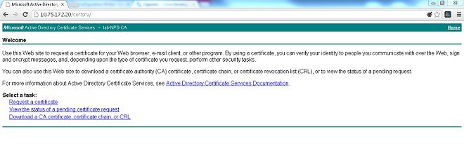
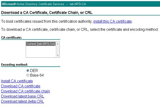
Exporting CA Server Certificate
Installing Industrial Operations Kit on the Server
Installing With the cisco_iok_config.exe Tool
Installing by Using the Configuration Template File
Monitoring Industrial Operations Kit Components
Viewing Information for All Components
Viewing Component-Specific Information
Obtaining Documentation and Submitting a Service Request
Industrial Operations Kit User Guide
The Industrial Operations Kit (IOK) virtual appliance serves as a controller to manage and monitor all the individual virtual machines (VMs) provided within the IOK. The IOK simplifies Field Area Network (FAN) deployment by automating the configuration of multiple network and security management system components as individual virtual machines within the Cisco UCS server (hereafter referred to as server). The virtual appliances are created during initial IOK software installation. For more information, see VMware Environment on Server.
Note: Follow the instructions in this guide to configure your IOK software. Otherwise, your system may not function normally.
■![]() Information About Industrial Operations Kit
Information About Industrial Operations Kit
■![]() Installing Industrial Operations Kit on the Server
Installing Industrial Operations Kit on the Server
■![]() Monitoring Industrial Operations Kit Components
Monitoring Industrial Operations Kit Components
Conventions
This document uses the following conventions.
Note: Means reader take note. Notes contain helpful suggestions or references to material not covered in the manual.
Caution: Means ![]() reader be careful. In this situation, you might perform an action that could result in equipment damage or loss of data.
reader be careful. In this situation, you might perform an action that could result in equipment damage or loss of data.
Warning: IMPORTANT SAFETY INSTRUCTIONS
Means danger. You are in a situation that could cause bodily injury. Before you work on any equipment, be aware of the hazards involved with electrical circuitry and be familiar with standard practices for preventing accidents. Use the statement number provided at the end of each warning to locate its translation in the translated safety warnings that accompanied this device.
SAVE THESE INSTRUCTIONS![]()
Regulatory: Provided for additional information and to comply with regulatory and customer requirements.
Information About Industrial Operations Kit
The Industrial Operations Kit (IOK) is a Cisco software solution that incorporates multiple virtual appliances for management, network, and security-related head-end network services for the Cisco Smart Grid Multi-Services Field Area Network Solution. The IOK software bundle download provides an entire head-end infrastructure (composed mostly of Cisco components) and the automation required for installation and on-going operations of that head-end infrastructure.
Figure 1 illustrates a typical Field Area Network (FAN). In this example, a Cisco 1000 Series Connected Grid Router (CGR or Cisco IOS router) communicates with the systems within the head-end infrastructure.
Within a FAN, each IOK can support up to 1000 of the following three Cisco IOS routers (end devices) in any combination:
Note: See Related Documentation for details on supporting documentation for all of the systems below.
■![]() Cisco 1000 Series Connected Grid Routers (CGR 1240 and CGR 1120), Cisco IOS Release 15.5(3)M, 15.5(2)T2, and 15.4(3)M4.
Cisco 1000 Series Connected Grid Routers (CGR 1240 and CGR 1120), Cisco IOS Release 15.5(3)M, 15.5(2)T2, and 15.4(3)M4.
Refer to the Release Notes for minimum software release and firmware requirements. The IOK does not communicate with Cisco 1000 Series routers running CG-OS.
■![]() Cisco 819 hardened Integrated Services Router (C819HG-4G-V-K9, C819HG-4G-A-K9, C819HG-U-K9, C819HGW-S-A-K9, and C819H-K9), Cisco IOS Release 15.6(1)T0a, 15.5(3)M1, 15.5(3)M, 15.5(2)T2, and 15.4(3)M4.
Cisco 819 hardened Integrated Services Router (C819HG-4G-V-K9, C819HG-4G-A-K9, C819HG-U-K9, C819HGW-S-A-K9, and C819H-K9), Cisco IOS Release 15.6(1)T0a, 15.5(3)M1, 15.5(3)M, 15.5(2)T2, and 15.4(3)M4.
■![]() Cisco 800 Series Industrial Integrated Services Routers (IR 809 and IR 829), Cisco IOS Release 15.5(3)M0a and 15.5(3)M.
Cisco 800 Series Industrial Integrated Services Routers (IR 809 and IR 829), Cisco IOS Release 15.5(3)M0a and 15.5(3)M.
Additionally, each IOK can support up to 250,000 IPv6 CG-mesh endpoints through the
Cisco Connected Grid WPAN Module for CG-Mesh deployment.
Note: The number of endpoints that IOK can support is limited by the license file of Cisco IoT Field Network Director
(IoT FND), which manages the connected grid systems.
Figure 1 shows a typical FAN deployment for Cisco IOS routers. IOK can operate with either an integrated RSA type CA server virtual appliance or an external CA server.
Note: IOK currently does not provide an integrated ECC type CA server.
Figure 1 Typical Field Area Network Deployment for Cisco IOS Routers

The functions of each of the following systems are handled by a separate virtual machine on the server:
■![]() Registration Authority (RA), which is based on Cisco 5921 Embedded Services Router (Cisco 5921 ESR), authenticates and authorizes incoming Simple Certificate Enrollment Protocol (SCEP) requests from the Cisco IOS router.
Registration Authority (RA), which is based on Cisco 5921 Embedded Services Router (Cisco 5921 ESR), authenticates and authorizes incoming Simple Certificate Enrollment Protocol (SCEP) requests from the Cisco IOS router.
■![]() Tunnel Proxy Server (TPS) for secure tunnel provisioning.
Tunnel Proxy Server (TPS) for secure tunnel provisioning.
■![]() Certificate Authority (CA) server, which grants all SCEP requests received from the RA.
Certificate Authority (CA) server, which grants all SCEP requests received from the RA.
■![]() IoT FND (based on Release 3.0 software or later), which manages the connected grid systems.
IoT FND (based on Release 3.0 software or later), which manages the connected grid systems.
■![]() Oracle database, which provides database services for IoT FND, is integrated into IoT FND.
Oracle database, which provides database services for IoT FND, is integrated into IoT FND.
■![]() Cisco Prime Access Registrar (CPAR), which provides TACACS+ service for CGR command authorization as well as RADIUS authentication and accounting services for CGR.
Cisco Prime Access Registrar (CPAR), which provides TACACS+ service for CGR command authorization as well as RADIUS authentication and accounting services for CGR.
Note: In IOK 2.0, CPAR is replaced by FreeRADIUS, which is integrated into Orchestration VM.
■![]() Head-end router (HER), which is based on Cisco Cloud Services Router 1000 Series (CSR1000V) that supports up to 1000 FlexVPN tunnels in total with up to five CSR1000V routers.
Head-end router (HER), which is based on Cisco Cloud Services Router 1000 Series (CSR1000V) that supports up to 1000 FlexVPN tunnels in total with up to five CSR1000V routers.
In addition to the functions above, a virtual appliance identified as Orchestration serves as a controller to manage provisioning of configurations across all of the other virtual appliances. The Orchestration virtual appliance is created during initial software installation. For more details, refer to VMware Environment on Server.
VMware Environment on Server
ESXi Hypervisor runs on the host server and provides a VMware layer upon which the virtual appliances operate.
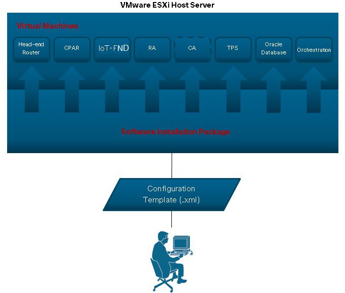
The software bundle provides a Windows 7 based executable installer that automatically deploys and configures each of the individual VMware virtual appliances onto the ESXi host server. Additionally, the installer brings up the Guest OS and application services by leveraging the customer-specific Configuration Template XML file. (See Figure 2.)
Note: Make sure that the ESXi server supports Red Hat Enterprise Linux (RHEL) Release 7.1(x86_64), which is the Guest OS for IoT FND.
You will enter key information such as IP addresses for all the virtual systems being configured in to the Configuration Template XML file.
Note: You must enter all the requested information in the Configuration Template XML file (detailed in the Prerequisites section) before![]() you can initiate the software install. In the Configuration Template XML file, you can also configure IOK to leverage Cisco IOS as the DHCPv6 server for CGRs to provide IPv6 addresses to the endpoints.
you can initiate the software install. In the Configuration Template XML file, you can also configure IOK to leverage Cisco IOS as the DHCPv6 server for CGRs to provide IPv6 addresses to the endpoints.
The IOK can operate with either an integrated Certification Authority (CA) server virtual appliance or an external Certification Authority (CA) server. If you use an external CA server, no CA virtual appliance will be installed as part of the process illustrated in Figure 2.
Figure 2 Installation of Virtual Machines on Server
During installation, the software records details on each step into the log file CISCO-IOK-STD-2.0.16_build-X\log\cisco_iok_installer.log. If the installation fails, the log file identifies the exact step that failed and the reason for the failure. When you resolve the issue and rerun the installation, it is recommended that you run a fresh installation.
You also have the option to overwrite the VMs by forcing a complete re-installation. In this case, the installer replaces all of the existing installed VMs and redoes all the steps.
Figure 3 shows an implementation with an external CA server; therefore, no virtual machine was defined and installed for the CA server.
Figure 3 Example Industrial Operations Kit Configuration Showing Port Mapping of Virtual Machines to DMZ and Data Center Networks with no CA Virtual Machine Installed

Note: Figure 3 only illustrates IPv4 addressing. IPv6 addressing might also be required when managing endpoints within the Industrial Operations Kit. You enter all IPv4 and IPv6 addresses relevant to the Industrial Operations Kit through the Configuration Template (.xml) as detailed in Table 1. The Windows 7 PC on which the software bundle installer resides must be able to reach the server through the Data Center network interface.
Note: Oracle is embedded in IoT FND so they have the same IP address. You do not need to configure the Oracle IP address in the cisco_iok_installer.xml![]() file.
file.
System Requirements
When using a Cisco UCS Server installed with all the virtual machines (ORCHESTRATION, IOT-FND, TPS, HERs (CSR1k, no more than five HERs), RA (Cisco 5921), and CA (internal server installation is optional; if you have an existing external CA server, we recommend you use that system), we recommend the following resource allocation for each VM.
The server must also meet the following additional requirements:
Prerequisites
■![]() You must have a valid license (production or evaluation) for VMware Hypervisor ESXi 5.1 Update 3 or ESXi™ 5.5 Update 2 with Redhat Enterprise Linux Release 7.1(x86_64) support, and it must be installed on the server before you install the Industrial Operations Kit software bundle.
You must have a valid license (production or evaluation) for VMware Hypervisor ESXi 5.1 Update 3 or ESXi™ 5.5 Update 2 with Redhat Enterprise Linux Release 7.1(x86_64) support, and it must be installed on the server before you install the Industrial Operations Kit software bundle.
■![]() You must have a production or evaluation license for IoT FND, an ESR license for RA, a CSR license for HER (only AX and SEC level license works with IOK).
You must have a production or evaluation license for IoT FND, an ESR license for RA, a CSR license for HER (only AX and SEC level license works with IOK).
■![]() Verify that you have the IOK software bundle available on a Windows 7 PC that can reach the VMware ESXi host server (Cisco UCS) through network connections.
Verify that you have the IOK software bundle available on a Windows 7 PC that can reach the VMware ESXi host server (Cisco UCS) through network connections.
■![]() Verify that the ESXi host server is active and has two Gigabit Ethernet ports available.
Verify that the ESXi host server is active and has two Gigabit Ethernet ports available.
■![]() Disconnect the ESXi host server from the VMware vCenter server application before installing the IOK software package.
Disconnect the ESXi host server from the VMware vCenter server application before installing the IOK software package.
■![]() Verify that the following virtual machine IP addresses that will be entered in to the Configuration Template do not conflict with one another:
Verify that the following virtual machine IP addresses that will be entered in to the Configuration Template do not conflict with one another:
–![]() Data center IP addresses for all virtual machines
Data center IP addresses for all virtual machines
–![]() DMZ IP addresses for TPS, RA, and Head-end router
DMZ IP addresses for TPS, RA, and Head-end router
–![]() IPv6 addresses used by IoT FND and the Head-end router
IPv6 addresses used by IoT FND and the Head-end router
–![]() DHCPv4 and DHCPv6 address pool
DHCPv4 and DHCPv6 address pool
–![]() Mesh IPv6 prefix delegation and other IPv6 prefix that is already existing in VM
Mesh IPv6 prefix delegation and other IPv6 prefix that is already existing in VM
■![]() Ensure that you have all the information listed in Table 1 available for entry into the Configuration Template.
Ensure that you have all the information listed in Table 1 available for entry into the Configuration Template.
We recommend using cisco_iok_config.exe to generate a new Configuration Template file. You can also use an HTML editor when entering values in the Configuration Template to ensure better clarity between the variable name and its brackets and the required value and to prevent accidental deletion of the brackets.
Example: <login>username</login>.
Missing brackets will result in an installation failure.
|
Note: If you do not enter a value in this template, you can enter this value during installation of the software. |
||
|
Note: Alternatively, you can enter this value during the software installation process. |
||
| Information required if you install an CA server virtual machine. |
||
|
Note: Sub CA is not supported in IOK 2.0. Do not enter value in this field. |
||
|
Operation IP addresses must be reserved for each of the following virtual machines (FND/Oracle, TPS, and Orchestration) installed on the server. (See
Figure 3.)
|
||
|
Information required for the Head-end router, Cisco CSR 1000V, that connects to both the Public Network (DMZ network) and Private Network (Data Center network). You must define at least one interface to each of the networks. (See
Figure 1).
|
||
|
Loopback interface reserved for FlexVPN virtual template. All defined FlexVPNs will use this interface for traffic forwarding.
Note: Interface can also be used by the FND and Data Center network for management purposes. IP addresses can be pulled from the IP pool defined in the <ip_management> section. |
||
|
Note: We recommend that you not configure the IPv6 loopback address. |
||
|
Information on the router, Cisco 5921 ESR, that serves as Registration Authority. You must define at least one interface to the Public Network (DMZ network) and one interface to the Private Network (Data Center network). (See
Figure 1).
|
||
|
Note: Interface must be reachable by field end devices before the secure tunnel is established. |
||
|
For router only deployment, leave this section unconfigured. |
||
| IPv6 address information for FND and Orchestration virtual machine interfaces in the Data Center network and in some cases the Service Provider data collection engine (CE). Note: The gateway IPv6 address is only required when CE is not in the subnet as the FND Virtual machine. Note: Ensure that the IPv6 addresses for FND, Orchestration and HER virtual machines are in the same subnet. |
||
|
Note: Optional configuration if the IPv6 DHCP server for mesh endpoints is configured on CGR 1000. |
||
(Optional) Only required when the IPv6 address for the CE is not in the same subnet as the FND virtual machine.Data center IPv6 gateway address. Only required if CE IPv6 is not in the same subnet as FND IPv6. |
||
Generating Certificates
Before installing the Industrial Operations Kit, you must generate certificates for the TPS and FND virtual machines, IoT Device Manager (IoT-DM), CGR, and RA.
This section includes the following topics:
■![]() Generating RSA Certificates for FND and TPS
Generating RSA Certificates for FND and TPS
Generating RSA Certificates for FND and TPS
If you are using an internal CA, ignore this section.
If you are using an external CA, refer to the “Generating Certificates for IoT FND and the IoT FND TPS Proxy” section in Cisco IoT Field Network Director User Guide, Release 3.0.x, for detailed information on generating RSA certificates for FND and TPS.
Generating ECC Certificates
The following sections describe enrolling the ECC certificates for Mesh. For the Radius ECC certificates, you can use the same process.
Note: The information in this section is for your reference only. For more details, refer to the Microsoft website.
This section includes the following topics:
■![]() Creating and Configuring the Template for CGE on the NPS
Creating and Configuring the Template for CGE on the NPS
■![]() Generating the CGE Certificates
Generating the CGE Certificates
■![]() Exporting CG Mesh Node Certificates
Exporting CG Mesh Node Certificates
Prerequisites
1.![]() Make sure that the following three roles have been added to your Windows 2008 server:
Make sure that the following three roles have been added to your Windows 2008 server:
–![]() Active Directory Domain Service
Active Directory Domain Service
–![]() Active Directory Certificate Services
Active Directory Certificate Services

2.![]() Make sure the following CA requirements are configured:
Make sure the following CA requirements are configured:
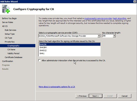
–![]() Cryptographic Service Provider: ECDSA_P256
Cryptographic Service Provider: ECDSA_P256
–![]() Hash algorithm for signing certificates: SHA256
Hash algorithm for signing certificates: SHA256
Creating and Configuring the Template for CGE on the NPS
Follow these steps to create and configure the template for CGE on the NPS:
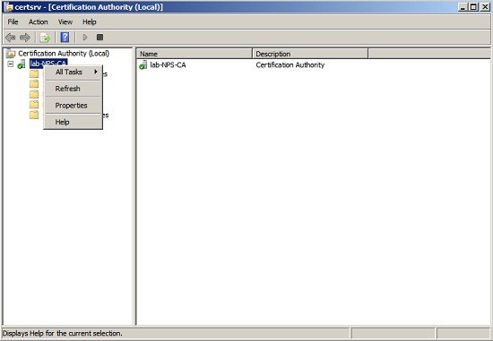
1.![]() Launch Certification Authority from within the Administrative Tools on the CA/Sub-CA Server running the ECC algorithm. Right-click and select Properties.
Launch Certification Authority from within the Administrative Tools on the CA/Sub-CA Server running the ECC algorithm. Right-click and select Properties.
a.![]() Select View Certificate and click the Details tab.
Select View Certificate and click the Details tab.
b.![]() Scroll down and check the Signature algorithm used is SHA256ECDSA. The Public key should be ECC (256 Bits).
Scroll down and check the Signature algorithm used is SHA256ECDSA. The Public key should be ECC (256 Bits).

3.![]() In the Certification Authority Console, right-click Certificate Templates in the left pane, right-click and select Manage.
In the Certification Authority Console, right-click Certificate Templates in the left pane, right-click and select Manage.

4.![]() Select and duplicate the Computer certificate template from the Certificates Console. Select Windows Server 2008 Enterprise for Windows.
Select and duplicate the Computer certificate template from the Certificates Console. Select Windows Server 2008 Enterprise for Windows.
5.![]() Fill in the certificate template as WorkStationEcc and select the Publish certificate in Active Directory check box.
Fill in the certificate template as WorkStationEcc and select the Publish certificate in Active Directory check box.

6.![]() On the Request Handling tab, choose Signature from the Purpose drop-down list. Select Yes in the Certificate Templates warning dialog. To allow certificate private key exports in the Request Handling tab, select Allow private key to be exported.
On the Request Handling tab, choose Signature from the Purpose drop-down list. Select Yes in the Certificate Templates warning dialog. To allow certificate private key exports in the Request Handling tab, select Allow private key to be exported.

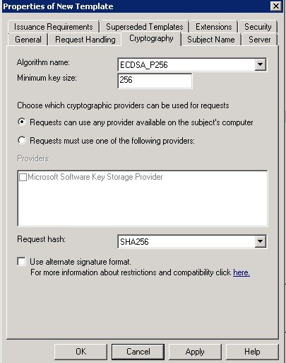
7.![]() On the Cryptography tab, choose ECDSA_P256 for the algorithm name. Enter 256 in the Minimum key size field. For the Request hash, choose SHA256.
On the Cryptography tab, choose ECDSA_P256 for the algorithm name. Enter 256 in the Minimum key size field. For the Request hash, choose SHA256.
8.![]() On the Subject Name tab, select Supply in the request to enter the Subject Name and Common Name. This can be the EUI64 MAC address string of a smart meter and is used for additional user authentication against the RADIUS server.
On the Subject Name tab, select Supply in the request to enter the Subject Name and Common Name. This can be the EUI64 MAC address string of a smart meter and is used for additional user authentication against the RADIUS server.

9.![]() On the Security tab, for all listed group or user names, ensure that the Enroll and Autoenroll permissions are selected.
On the Security tab, for all listed group or user names, ensure that the Enroll and Autoenroll permissions are selected.

10.![]() Close the Certificate Template Console and select the Certificate Templates folder from the Certification Authority Console.
Close the Certificate Template Console and select the Certificate Templates folder from the Certification Authority Console.
a.![]() Select New, and then set Certificate Template to Issue.
Select New, and then set Certificate Template to Issue.
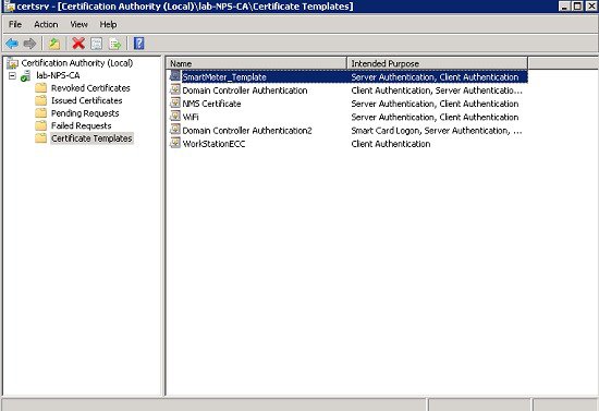
b.![]() Select the new certificate template, WorkStationEcc, and then click OK. The new certificate template should be listed within the Certificate Templates folder of the Certification Authority Console.
Select the new certificate template, WorkStationEcc, and then click OK. The new certificate template should be listed within the Certificate Templates folder of the Certification Authority Console.
Generating the CGE Certificates
The following steps guide the administrator of the NPS servers to generate a certificate from the CA using the template that was created above (WorkStationEcc).
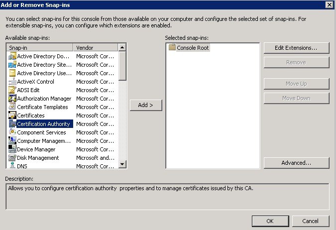
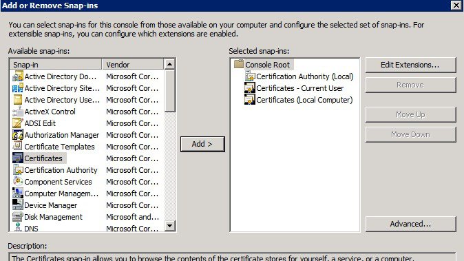
1.![]() Open the MMC (Microsoft Management Console) application on Windows Server 2008 R2 (Run -> mmc) and make sure that the Local Computer Certificates Snap-In is loaded. But for the first configuration for MMC, you can click File and Add/Remove Snap-in… and a popup window displays.
Open the MMC (Microsoft Management Console) application on Windows Server 2008 R2 (Run -> mmc) and make sure that the Local Computer Certificates Snap-In is loaded. But for the first configuration for MMC, you can click File and Add/Remove Snap-in… and a popup window displays.

Select Certificate Authority in the left pane and click Add >. Click OK.
Select Local Computer and click Finish.

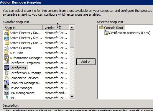
In the Add or Remove Snap-ins window, select Certificates in the left pane and click Add >. Click OK.
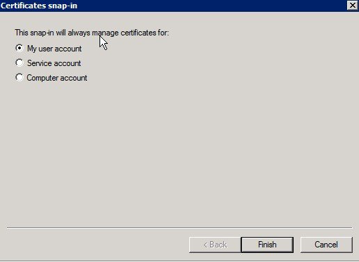
Select My user account and click Finish.
In the Add or Remove Snap-ins window, select Certificates in the left pane and click Add >. Click OK.
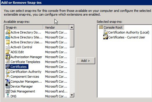
Select Computer account and click Next.

Select Local Computer and click Finish.

The items are added in the right pane. Click OK.

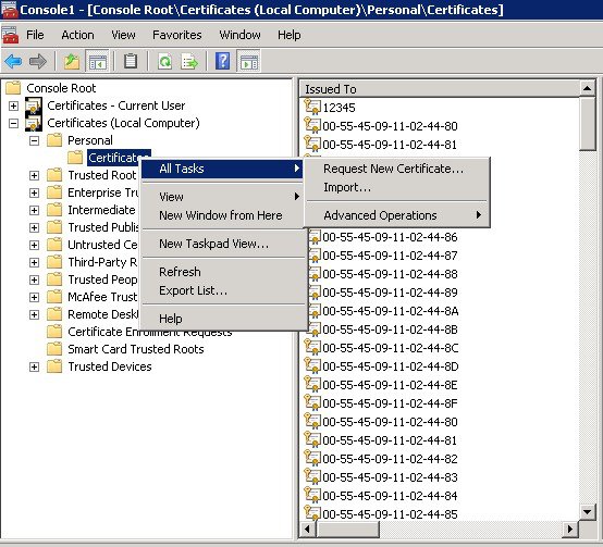
2.![]() Go to Personal -> Certificates -> All Tasks -> Request New Certificate.
Go to Personal -> Certificates -> All Tasks -> Request New Certificate.

4.![]() Select Active Directory Enrollment Policy and click Next.
Select Active Directory Enrollment Policy and click Next.

5.![]() Select WorkStationEcc and click on the more information link below it.
Select WorkStationEcc and click on the more information link below it.
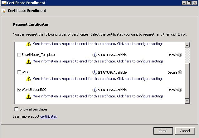
6.![]() In the Subject tab, choose Common name from the Type drop-down list. After filling in EUI, click Add >, and then click OK.
In the Subject tab, choose Common name from the Type drop-down list. After filling in EUI, click Add >, and then click OK.

7.![]() Click Enroll and click Finish when enroll is completed.
Click Enroll and click Finish when enroll is completed.

Exporting CG Mesh Node Certificates
There are two certificates that need to be exported. One certificate is with the private key and public key. The other is with the public key only. The one with private key will be programmed into meter. The public key will be added to Active Directory.
This section includes the following topics:
Exporting Certificate with Private Key
1.![]() Return to the MMC application and highlight the newly created certificate (00173b0b0039003c). Right click and select All Tasks > Export.
Return to the MMC application and highlight the newly created certificate (00173b0b0039003c). Right click and select All Tasks > Export.

2.![]() Follow the export wizard to the next screen. Select Yes, export the private key.
Follow the export wizard to the next screen. Select Yes, export the private key.

3.![]() Select Include all certificates in the certification path if possible. This includes the CA certificate.
Select Include all certificates in the certification path if possible. This includes the CA certificate.

4.![]() Enter password for certificate which will be used in CGE. For default settings, use the password Cisco123.
Enter password for certificate which will be used in CGE. For default settings, use the password Cisco123.


6.![]() Securely transfer the.pfx file from the Desktop to the FND server.
Securely transfer the.pfx file from the Desktop to the FND server.
7.![]() For security reasons, it is highly recommended that you delete the.pfx file from the Desktop and empty the Recycle Bin on Windows.
For security reasons, it is highly recommended that you delete the.pfx file from the Desktop and empty the Recycle Bin on Windows.
Exporting Certificate with Public Key
1.![]() Return to the MMC application and highlight the newly created certificate (00173b0b0039003c). Right click and select All Tasks > Export.
Return to the MMC application and highlight the newly created certificate (00173b0b0039003c). Right click and select All Tasks > Export.

2.![]() Follow the export wizard to the next screen. Select No, do not export the private key.
Follow the export wizard to the next screen. Select No, do not export the private key.

3.![]() Select export file format DER encoded binary X.509 (.CER). Click Next >.
Select export file format DER encoded binary X.509 (.CER). Click Next >.


Installing Industrial Operations Kit on the Server
The Windows 7 installer includes all necessary scripts and dependent libraries to create the various VMware machines for the various systems noted in Figure 2 on the server (ESXi host).
Ensure that all Prerequisites are met.
Before you install the Industrial Operations Kit (IOK) software bundle, you must disconnect the server from the VMware vCenter server application, if in use within your network. You can reconnect to this application when the software installation completes.
Get the IOK software bundle to a Windows 7 PC, and unzip it.
There are two ways to install the software on the server. If you do not need to configure mesh node, there is no need to configure ECC certificates. If you want to configure IOK with ECC certificate, use the cisco_iok_config.exe tool; otherwise, modify the configuration xml (configuration template) manually and then run the cisco_iok_installer.exe. The detailed steps are described in the following sections:
■![]() Installing With the cisco_iok_config.exe Tool
Installing With the cisco_iok_config.exe Tool
■![]() Installing by Using the Configuration Template File
Installing by Using the Configuration Template File
Note: After the installation completes, we recommend that you not change the settings of the VM configuration.
Installing With the cisco_iok_config.exe Tool
This section provides the procedures of using cisco_iok_config.exe to generate a new configuration template file and install the IOK software on the server.
1.![]() Double-click the cisco_iok_config.exe file located at /path/to/unziped softerware bundle/. The ESXi Provision window displays.
Double-click the cisco_iok_config.exe file located at /path/to/unziped softerware bundle/. The ESXi Provision window displays.
2.![]() Enter basic ESXi information (Username, Password, and IP address) and click Next >.
Enter basic ESXi information (Username, Password, and IP address) and click Next >.

Note: If you have already configured a cisco_iok_installer.xml file, you can import the settings of this file to the cisco_iok_config.exe tool by clicking Import![]() on the screen. After that, click Next > on each screen and you can change the existing values or input new values for the fields.
on the screen. After that, click Next > on each screen and you can change the existing values or input new values for the fields.
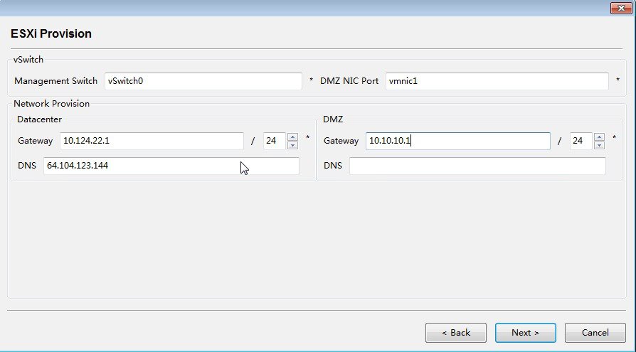
3.![]() Enter the ESXi provisioning information and then click Next >.
Enter the ESXi provisioning information and then click Next >.
4.![]() Enter the NTP server information and click Next >.
Enter the NTP server information and click Next >.

5.![]() Choose to use external CA or internal CA, and click Next >.
Choose to use external CA or internal CA, and click Next >.
If you choose to use external CA, see Generating Certificates for the instructions on generating the certificates. In the following example, we choose to use internal CA (uncheck the Use external CA checkbox).

6.![]() Enter internal CA information and click Next >.
Enter internal CA information and click Next >.

7.![]() Enter the certificate information and then click Next >. For more information on generating ECC certificates, see the Generating ECC Certificates. If you do not need to configure mesh, you are recommended to install by manually modifying the cisco_iok_installer.xml.template file
Enter the certificate information and then click Next >. For more information on generating ECC certificates, see the Generating ECC Certificates. If you do not need to configure mesh, you are recommended to install by manually modifying the cisco_iok_installer.xml.template file

8.![]() Enter the VM information and click Next >.
Enter the VM information and click Next >.

9.![]() Enter the RA VM information and click Next >.
Enter the RA VM information and click Next >.

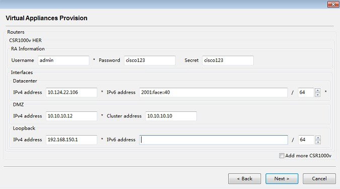
10.![]() Enter the CSR VM information. If you want to configure more than one CSR, check the Add more CSR1000v checkbox. Then click Next >.
Enter the CSR VM information. If you want to configure more than one CSR, check the Add more CSR1000v checkbox. Then click Next >.
11.![]() Enter the IPv6 addresses for the VMs and click Next >.
Enter the IPv6 addresses for the VMs and click Next >.

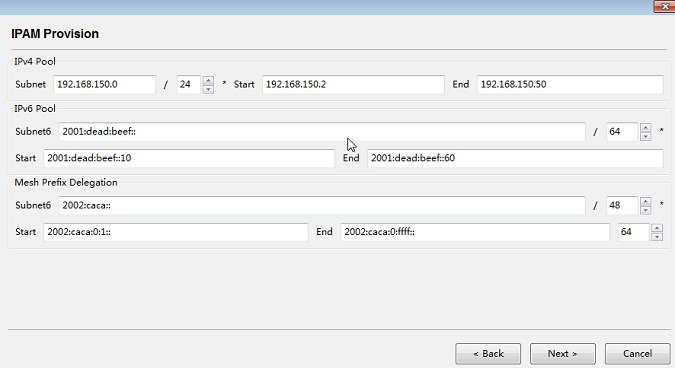
12.![]() Enter the DHCP server information, which is embedded in the Orchestration VM, and then click Next >.
Enter the DHCP server information, which is embedded in the Orchestration VM, and then click Next >.
13.![]() Click Uninstall to uninstall the previously installed version.
Click Uninstall to uninstall the previously installed version.
Note: You can preview the configuration file by clicking Preview![]() or save the file as cisco_iok_installer.xml in the software folder by clicking Save as. When you click Uninstall or Install, the cisco_iok_installer.xml file will be saved automatically.
or save the file as cisco_iok_installer.xml in the software folder by clicking Save as. When you click Uninstall or Install, the cisco_iok_installer.xml file will be saved automatically.
Note: If you already installed release 2.0.12, you need a fresh install to upgrade to release 2.0.16.

14.![]() Enter Y at the command line to proceed the uninstallation.
Enter Y at the command line to proceed the uninstallation.

15.![]() When the uninstall completes, press Enter to return to the main configuration window.
When the uninstall completes, press Enter to return to the main configuration window.

16.![]() Click Install to execute the installation process.
Click Install to execute the installation process.

Installing by Using the Configuration Template File
As an option, if you do not use the cisco_iok_config.exe tool to generate the configuration template file and install the software, you can use the Configuration Template (.xml) to manually generate a cisco_iok_installer.xml file and then run the cisco_iok_installer.exe.
1.![]() Copy the Configuration Template (.xml), cisco_iok_installer.xml.template and rename it to cisco_iok_installer.xml, and use an HTML editor to enter the requested information.
Copy the Configuration Template (.xml), cisco_iok_installer.xml.template and rename it to cisco_iok_installer.xml, and use an HTML editor to enter the requested information.
An example of cisco_iok_installer.xml is shown below. The field in bold indicates that the information needs user entry. For more information on each field, see Table 1.
Example Cisco Industrial Operations Kit Configuration Template File
The template comes with the Industrial Operations Kit software bundle. (See Table 1 for details on required information.)
2.![]() Double-click cisco_iok_uninstall.exe to uninstall the previous installation if any.
Double-click cisco_iok_uninstall.exe to uninstall the previous installation if any.
3.![]() To install the software bundle on the server, double click cisco_iok_installer.exe (recommended) or
To install the software bundle on the server, double click cisco_iok_installer.exe (recommended) or
execute it from DOS command line, with or without the --overwrite option.
Note: If you specify the --overwrite option, the previous installation will be overwritten. The --overwrite option equates to a fresh installation.
Note: If you already installed release 2.0.12, you need a fresh install to upgrade to release 2.0.16.
–![]() Software automatically configures the networking connections for the server and then installs, provisions, and brings up each individual virtual machine and its application services.
Software automatically configures the networking connections for the server and then installs, provisions, and brings up each individual virtual machine and its application services.
(See Installation of Virtual Machines on ServerFigure 2.)
–![]() We highly recommend that you change the default root password when prompted at the end of the installation.
We highly recommend that you change the default root password when prompted at the end of the installation.
–![]() When the install completes successfully, the following statement is displaysedon the screen:
When the install completes successfully, the following statement is displaysedon the screen:
Monitoring Industrial Operations Kit Components
After you successfully install the software, you can access the Industrial Operations Kit (IOK) GUI. Errors are logged in an HTML log, which you can access through a browser.
You can monitor the Industrial Operations Kit by using the Orchestration Web Services at:
<orch_ipv4> is the Orchestration operation ip that you set in the cisco_iok_config.exe tool or you manually entered in the Configuration Template (.xml).
For more information, see GUI Overview.
Note: The monitoring activity described above is distinct from that provided by IoT-FND.
GUI Overview
This section explains using the Industrial Operations Kit (IOK) GUI to manage and monitor the head-end infrastructure. Installation and configuration file provisioning are described in the Installing Industrial Operations Kit on the Server.
Note: When using online publications, reference documents matching the Cisco IOS software version running on the routers and switches in your network, and the IoT-FND user manual installed on the FND server.
The IOK GUI allows you to manage FAN configuration and provisioning using the following VMs (Figure 3) configured during IOK installation:
■![]() CISCO-IOK-FND—This is the FND FAN management service.
CISCO-IOK-FND—This is the FND FAN management service.
■![]() CISCO-IOK-TPS—This is the secure tunnel provisioning service.
CISCO-IOK-TPS—This is the secure tunnel provisioning service.
■![]() CISCO-IOK-ORCHESTRATION—This is the orchestration and management services for all Industrial Operations Kit components.
CISCO-IOK-ORCHESTRATION—This is the orchestration and management services for all Industrial Operations Kit components.
■![]() CISCO-IOK-HER—This is the Head-end Router service (based on the Cisco CSR 1000V).
CISCO-IOK-HER—This is the Head-end Router service (based on the Cisco CSR 1000V).
■![]() CISCO-IOK-RA—This is the Registration Authority (RA) service (based on the Cisco ESR 5921).
CISCO-IOK-RA—This is the Registration Authority (RA) service (based on the Cisco ESR 5921).
This section describes the Industrial Operations Kit GUI, including:
■![]() Router ZTD Staging Dialog Box
Router ZTD Staging Dialog Box
Logging In
Use one of the following supported browsers to access the Industrial Operations Kit GUI:
■![]() Internet Explorer (IE): 9.0 or higher
Internet Explorer (IE): 9.0 or higher
■![]() Mozilla Firefox: 3.5 or higher
Mozilla Firefox: 3.5 or higher
To start the Industrial Operations Kit GUI:
1.![]() In your browser, enter the IP address of the Orchestration server.
In your browser, enter the IP address of the Orchestration server.
Note: This must be an https secure access.
2.![]() Accept the site security certificate.
Accept the site security certificate.
3.![]() Enter the default login information:
Enter the default login information:
Note: The FND deployed by IOK has the same default username root![]() and password root123.
and password root123.
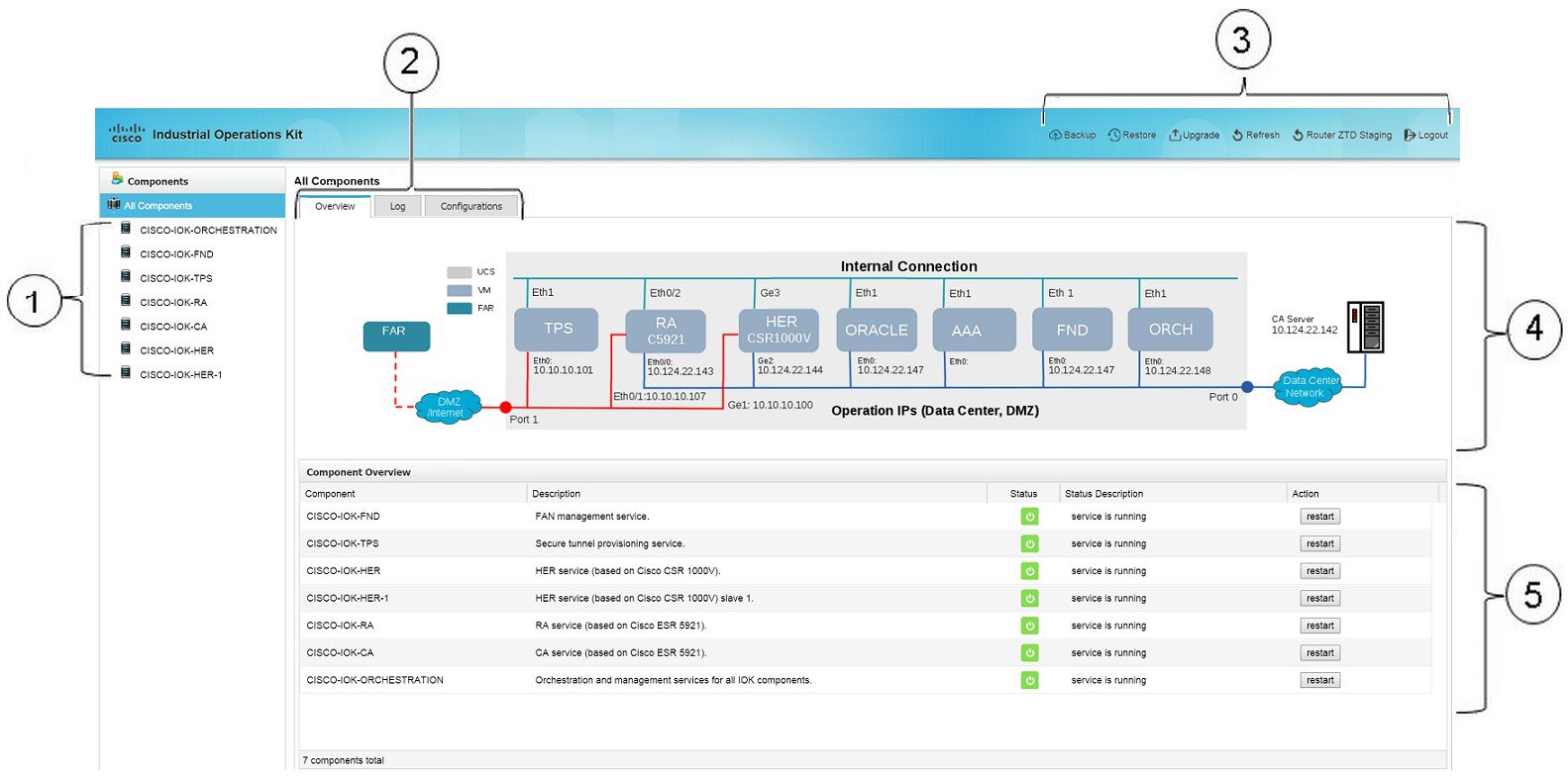
Figure 4 highlights elements of the opening page.
Figure 4 IOK Head-end GUI Opening Page Elements
Components Pane
The Components pane (item 11 in Figure 4) lists all VMs installed and configured during Industrial Operations Kit installation. Select a component in this pane to view its configuration details in the Information pane (item 12 in Figure 4).
Information Pane
The Information pane displays component-related information. This section describes the following:
■![]() Viewing Information for All Components
Viewing Information for All Components
Viewing Information for All Components
At log in, All Components displays in the Components pane by default. The Overview tab displays a virtual network diagram (Figure 5). This snapshot of your virtual network starts at the left with the FAR (end node), and ends at the right with the Certification Authority (CA) server. The diagram displays IP addresses for all IOK VMs. The following states signify the network connection status:
■![]() A red line indicates that the DMZ network connects through UCS port 1.
A red line indicates that the DMZ network connects through UCS port 1.
■![]() A green line indicates internal connections (that is, it is not connected to any UCS port).
A green line indicates internal connections (that is, it is not connected to any UCS port).
■![]() A blue line indicates a connection to the Data Center network through UCS port 0.
A blue line indicates a connection to the Data Center network through UCS port 0.
■![]() A solid network connection line indicates a direct connection.
A solid network connection line indicates a direct connection.
■![]() A dashed network connection line indicates that it is not a direct connection (for example, the connection may be through a public network such as a cellular network).
A dashed network connection line indicates that it is not a direct connection (for example, the connection may be through a public network such as a cellular network).

Note that the CGR or FAN device must go through the RA and TPS VM services to establish a secure tunnel with the HER. Before this tunnel is established, the device cannot reach the data center network.
Viewing the Current Configuration Template
The Configurations tab displays the current Configuration Template XML file. You configure this file during the Industrial Operations Kit installation.
Viewing Component-Specific Information
When you select a component in the Components pane, the Information pane tabs display basic information and logs.
Components Overview Tab
The Overview tab displays component elements and assigned values, including:
Components Logs Tab
The Logs tab displays log messages and associated severity levels:
■![]() INFO–These are the lowest severity level log messages.
INFO–These are the lowest severity level log messages.
■![]() WARNING–These log messages are generated on service status changes (for example, on a VM restart).
WARNING–These log messages are generated on service status changes (for example, on a VM restart).
■![]() ERROR–These messages are generated for critical events and exceptions.
ERROR–These messages are generated for critical events and exceptions.
Managing IOK VM Licenses
On the Information pane, you can import license files to the following VMs:
To import a license to an IOK VM:
1.![]() In the Components pane, select the desired VM.
In the Components pane, select the desired VM.
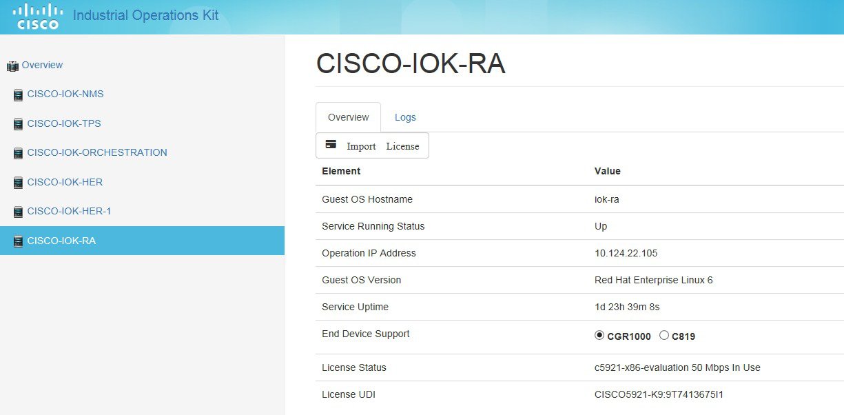
2.![]() In the Information pane on the Overview tab, click Import License.
In the Information pane on the Overview tab, click Import License.

3.![]() Click Browse to navigate to the desired valid license file.
Click Browse to navigate to the desired valid license file.
You must select the proper service license file type when importing licenses.
Buttons
Along the upper-right in the top banner (item 3 in IOK Head-end GUI Opening Page Elements) are the following buttons.

|
Note: Backups cannot be canceled. You must confirm the backup at the prompt. When complete, a pop-up window shows that the backup is completed. |

|
Restores all VMs to the selected backup restore point. Backups are listed by date, latest at the top. |

|
Upgrades all VMs to the selected upgrade tarball. Note: If you already installed release 2.0.12, you need a fresh install to upgrade to release 2.0.16. |

|
Refreshes the view, and returns to the All Components Overview page. |

|
Accesses the Router ZTD Staging Dialog Box. |

|
Component Overview Pane
Select All Components to display the Component Overview pane (item 4 in Figure 4) at the bottom of the Information pane. The Component Overview lists the VMs, their status (Up  or Down
  ) and description, and allows you to restart the VM service.
You must confirm that the Industrial Operations Kit VM restarts at the prompt. Also, the Industrial Operations Kit GUI is unavailable during ORCHESTRATION VM restarts.
Router ZTD Staging Dialog Box
Use the Router ZTD Staging dialog box to begin zero-touch deployment (ZTD) on assigned CGRs.
To begin router ZTD configuration:
1.![]() Click the Router ZTD Staging button.
Click the Router ZTD Staging button.
The Router ZTD Staging dialog box displays.
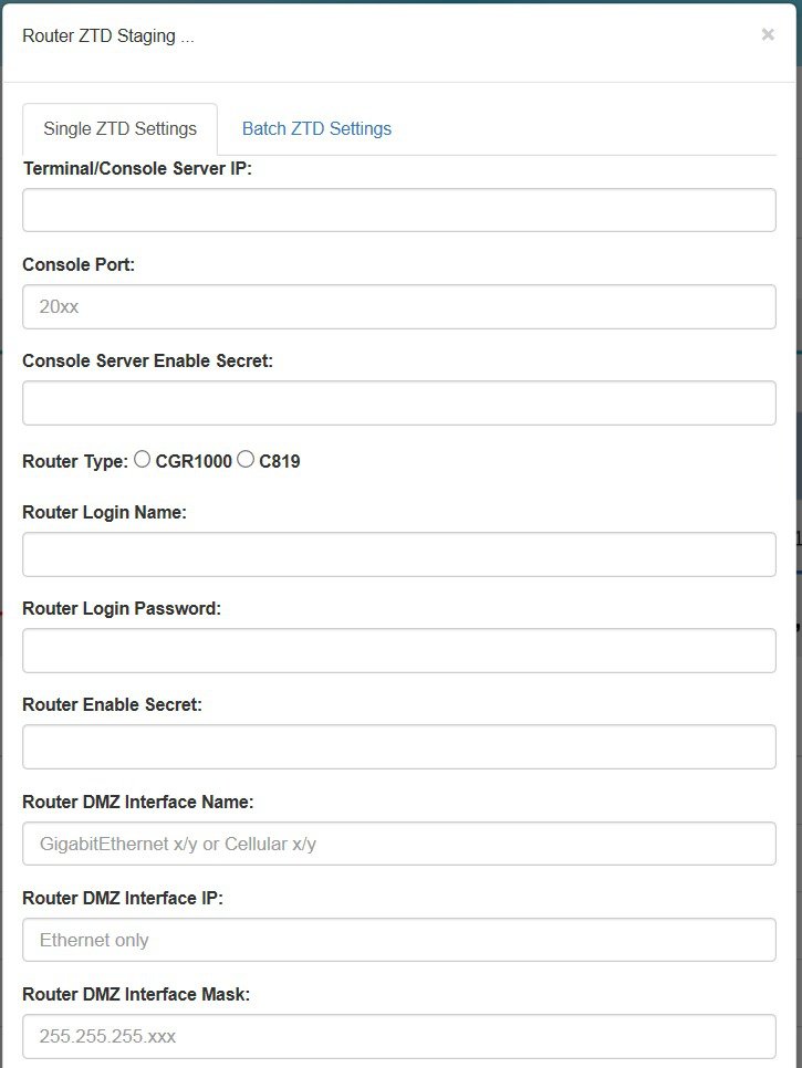
Note: For the Router Type![]() field, C819 does not support mesh.
field, C819 does not support mesh.
If you choose to configure single ZTD settings, for the Enable Mesh Configuration field, you can choose to
–![]() Enable mesh with prefix delegation (PD), with the prerequisite that you have configured PD in the cisco_iok_config.exe tool or the Configuration Template (.xml).
Enable mesh with prefix delegation (PD), with the prerequisite that you have configured PD in the cisco_iok_config.exe tool or the Configuration Template (.xml).
The following figure shows the ZTD settings that enable mesh with prefix delegation (PD) configured.

The following figure shows the ZTD settings that enable mesh without PD configured.

The following figure shows the ZTD settings that disable mesh configuration.

2.![]() If you choose batch ZTD settings, click on the Batch ZTD Settings tab and then click the Browse... button to import a.csv file from your local drive that contains all necessary field values to complete the batch ZTD settings.
If you choose batch ZTD settings, click on the Batch ZTD Settings tab and then click the Browse... button to import a.csv file from your local drive that contains all necessary field values to complete the batch ZTD settings.

An example of the batch ZTD.csv file is as following. The first row contains the fields. The values of each field for the first device are listed in the second row. The values for the second device are listed in the third row. If you have more devices, add more rows to input the values.
Note: ZTD staging takes approximately 10–15 minutes. Output messages display in the bottom pane.
Feature History
Related Documentation
Release Notes for IoT Field Network Director, Release 3.0
Cisco IoT Field Network Director User Guide 3.0.x
North Bound API User Guide for the Cisco IoT Field Network Director 3.0.x
Cisco 5921 Embedded Services Router
Cisco CSR 1000V Series Cloud Services Router Software Configuration Guide
Cisco 1000 Series Connected Grid Routers Configuration Guides and Release Notes
Cisco 800 Series Integrated Services Routers Software Configuration Guide
Cisco 800 Series Industrial Integrated Services Routers (IR 800)
Obtaining Documentation and Submitting a Service Request
For information on obtaining documentation, using the Cisco Bug Search Tool (BST), submitting a service request, and gathering additional information, see What’s New in Cisco Product Documentation at: http://www.cisco.com/c/en/us/td/docs/general/whatsnew/whatsnew.html.
Subscribe to What’s New in Cisco Product Documentation, which lists all new and revised Cisco technical documentation as an RSS feed and delivers content directly to your desktop using a reader application. The RSS feeds are a free service.
THE SPECIFICATIONS AND INFORMATION REGARDING THE PRODUCTS IN THIS MANUAL ARE SUBJECT TO CHANGE WITHOUT NOTICE. ALL STATEMENTS, INFORMATION, AND RECOMMENDATIONS IN THIS MANUAL ARE BELIEVED TO BE ACCURATE BUT ARE PRESENTED WITHOUT WARRANTY OF ANY KIND, EXPRESS OR IMPLIED. USERS MUST TAKE FULL RESPONSIBILITY FOR THEIR APPLICATION OF ANY PRODUCTS.
THE SOFTWARE LICENSE AND LIMITED WARRANTY FOR THE ACCOMPANYING PRODUCT ARE SET FORTH IN THE INFORMATION PACKET THAT SHIPPED WITH THE PRODUCT AND ARE INCORPORATED HEREIN BY THIS REFERENCE. IF YOU ARE UNABLE TO LOCATE THE SOFTWARE LICENSE OR LIMITED WARRANTY, CONTACT YOUR CISCO REPRESENTATIVE FOR A COPY.
The Cisco implementation of TCP header compression is an adaptation of a program developed by the University of California, Berkeley (UCB) as part of UCB’s public domain version of the UNIX operating system. All rights reserved. Copyright © 1981, Regents of the University of California.
NOTWITHSTANDING ANY OTHER WARRANTY HEREIN, ALL DOCUMENT FILES AND SOFTWARE OF THESE SUPPLIERS ARE PROVIDED “AS IS” WITH ALL FAULTS. CISCO AND THE ABOVE-NAMED SUPPLIERS DISCLAIM ALL WARRANTIES, EXPRESSED OR IMPLIED, INCLUDING, WITHOUT LIMITATION, THOSE OF MERCHANTABILITY, FITNESS FOR A PARTICULAR PURPOSE AND NONINFRINGEMENT OR ARISING FROM A COURSE OF DEALING, USAGE, OR TRADE PRACTICE.
IN NO EVENT SHALL CISCO OR ITS SUPPLIERS BE LIABLE FOR ANY INDIRECT, SPECIAL, CONSEQUENTIAL, OR INCIDENTAL DAMAGES, INCLUDING, WITHOUT LIMITATION, LOST PROFITS OR LOSS OR DAMAGE TO DATA ARISING OUT OF THE USE OR INABILITY TO USE THIS MANUAL, EVEN IF CISCO OR ITS SUPPLIERS HAVE BEEN ADVISED OF THE POSSIBILITY OF SUCH DAMAGES.
Any Internet Protocol (IP) addresses and phone numbers used in this document are not intended to be actual addresses and phone numbers. Any examples, command display output, network topology diagrams, and other figures included in the document are shown for illustrative purposes only. Any use of actual IP addresses or phone numbers in illustrative content is unintentional and coincidental.
All printed copies and duplicate soft copies are considered un-Controlled copies and the original on-line version should be referred to for latest version.
Cisco has more than 200 offices worldwide. Addresses, phone numbers, and fax numbers are listed on the Cisco website at www.cisco.com/go/offices.
Cisco and the Cisco logo are trademarks or registered trademarks of Cisco and/or its affiliates in the U.S. and other countries. To view a list of Cisco trademarks, go to this URL: www.cisco.com/go/trademarks. Third-party trademarks mentioned are the property of their respective owners. The use of the word partner does not imply a partnership relationship between Cisco and any other company. (1110R)
No combinations are authorized or intended under this document.
Contact Cisco
- Open a Support Case

- (Requires a Cisco Service Contract)


 Feedback