- Preface
- Overview
- Installing and Removing Power Components
- Installing and Removing Air Circulation Components
- Installing and Removing SFCs, RPs, MSCs, FPs, LSPs, PLIMs, and Associated Components
- Installing and Removing the Front Doors and Grille
- Cisco CRS 4-Slot Line Card Chassis System Specifications
- Index
Cisco CRS Carrier Routing System 4-Slot Line Card Chassis Installation Guide
Bias-Free Language
The documentation set for this product strives to use bias-free language. For the purposes of this documentation set, bias-free is defined as language that does not imply discrimination based on age, disability, gender, racial identity, ethnic identity, sexual orientation, socioeconomic status, and intersectionality. Exceptions may be present in the documentation due to language that is hardcoded in the user interfaces of the product software, language used based on RFP documentation, or language that is used by a referenced third-party product. Learn more about how Cisco is using Inclusive Language.
- Updated:
- April 8, 2011
Chapter: Installing and Removing Power Components
Installing and Removing Power Components
This chapter provides instructions on how to install and remove the Cisco CRS Carrier Routing System 4-Slot Line Card Chassis power components.
This chapter presents the following topics:
•![]() About Installing and Removing the Power Components
About Installing and Removing the Power Components
•![]() DC Power Systems on the Cisco CRS 4-Slot Router
DC Power Systems on the Cisco CRS 4-Slot Router
About Installing and Removing the Power Components
This section contains some general information about the power components.
•![]() Basic Chassis Power Recommendations
Basic Chassis Power Recommendations
•![]() Supplemental Unit Bonding and Grounding Guidelines
Supplemental Unit Bonding and Grounding Guidelines
•![]() AC Power Supply Cord Illustrations and Plug Types
AC Power Supply Cord Illustrations and Plug Types
•![]() Powering the Chassis Up or Down
Powering the Chassis Up or Down
Basic Chassis Power Recommendations
The Cisco CRS Carrier Routing System 4-Slot Line Card Chassis can be configured with either an AC-input power subsystem or a DC-input power subsystem. Site power requirements differ depending on the source voltage used. Follow these precautions and recommendations when planning power connections to the router:
•![]() Check the power at your site before installation and periodically after installation to ensure that you are receiving clean power. Install a power conditioner, if necessary.
Check the power at your site before installation and periodically after installation to ensure that you are receiving clean power. Install a power conditioner, if necessary.
•![]() Install proper grounding to avoid damage from lightning and power surges.
Install proper grounding to avoid damage from lightning and power surges.

The Cisco CRS 4-slot line card chassis requires that at least the power shelves and their components be installed to operate properly. Two types of power shelves exist: an AC shelf and a DC shelf. An AC power shelf houses AC rectifiers, while a DC power shelf houses the DC power input module (PIM) and DC power input shelf (which encloses the DC power supplies). We recommend that you use only one type of power shelf in a chassis at a time.
 |
Warning |
The Cisco CRS 4-slot line card chassis is shipped fully populated with a power shelf that contains four power supplies for power redundancy. See the appropriate installation section (see "Installing a DC Power Shelf" section or "Installing an AC Power Shelf" section) for detailed installation information.
As viewed from the front (PLIM) side of the chassis, the left two power supplies feed output A, while the right two power supplies feed output B.
For 2N redundancy, the power input on rear (SFC) side of the chassis should be from two different branch sources, with the left two input connections to one branch source and the right two to the other branch source. With this configuration the router remains fully powered in case one branch source fails. In normal operation all power supplies should be installed.
Be sure to install the power shelf before installing the power supplies.
Supplemental Unit Bonding and Grounding Guidelines
Although the router chassis has a safety earth ground connection as part of the power cabling to the power shelf, the chassis includes an option that allows you to connect the central office ground system or interior equipment ground system to the supplemental bonding and grounding receptacles on the router chassis. Two ground studs are located on the rear (SFC) side of the chassis. (see Figure 2-1). This ground point is also called the network equipment building system (NEBS) bonding and grounding stud.

Note ![]() These bonding and grounding receptacles satisfy the Telcordia® NEBS requirements for supplemental bonding and grounding connections. If you are not installing the router in a NEBS environment, you can choose to bypass these guidelines and rely on the safety earth ground connection for the power shelf.
These bonding and grounding receptacles satisfy the Telcordia® NEBS requirements for supplemental bonding and grounding connections. If you are not installing the router in a NEBS environment, you can choose to bypass these guidelines and rely on the safety earth ground connection for the power shelf.
Figure 2-1 NEBS Bonding and Grounding Points (Rear of Chassis)

|
|
NEBS bonding and grounding stud |
If you plan to connect the Cisco CRS 4-slot line card chassis system to a network equipment building system (NEBS)-compliant supplemental bonding and grounding system at the site, you must have the following:
•![]() A minimum of one ground lug that has two M6 bolt holes with 0.625-inch (15.86-mm) spacing between them, and a wire receptacle large enough to accept a 6-AWG or larger multistrand copper wire. The lug is similar to the type used for the DC-input power supply leads. This ground lug is not available from Cisco Systems. This type of lug is available from electrical-connector vendors, such as Panduit.
A minimum of one ground lug that has two M6 bolt holes with 0.625-inch (15.86-mm) spacing between them, and a wire receptacle large enough to accept a 6-AWG or larger multistrand copper wire. The lug is similar to the type used for the DC-input power supply leads. This ground lug is not available from Cisco Systems. This type of lug is available from electrical-connector vendors, such as Panduit.
•![]() Two M6 nuts with locking washers (nickel-plated brass is ideal). This hardware is not available from Cisco Systems; they are available from any commercial hardware vendor.
Two M6 nuts with locking washers (nickel-plated brass is ideal). This hardware is not available from Cisco Systems; they are available from any commercial hardware vendor.
•![]() A commensurately rated ground wire. The actual wire diameter and length depend on your router location and site environment. This wire is not available from Cisco Systems; it is available from any commercial cable vendor.
A commensurately rated ground wire. The actual wire diameter and length depend on your router location and site environment. This wire is not available from Cisco Systems; it is available from any commercial cable vendor.
Note ![]() The DC return of this system should remain isolated from the system frame and chassis (DC-I: Isolated DC Return).
The DC return of this system should remain isolated from the system frame and chassis (DC-I: Isolated DC Return).
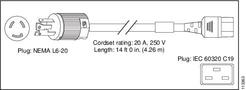
AC Power Supply Cord Illustrations and Plug Types
This section contains the AC power cord illustrations and a table of power plug types for the Cisco CRS Carrier Routing System 4-Slot Line Card Chassis for Australia (AU), European (EU), Italy (IT), United Kingdom (UK), United States (USA), and Japan.
|
|
|
|---|---|
AU20S3 |
Australia—Figure 2-2 |
CEE 7/7 |
European—Figure 2-3 |
CEI 23-50 |
Italian—Figure 2-4 |
BS 1363 |
United Kingdom—Figure 2-5 |
NEMA L6-20 |
United States and Japan—Figure 2-6 |
Figure 2-2 CAB-CRS4AC-AU

Figure 2-3 CAB-CRS4AC-EU

Figure 2-4 CAB-CRS4AC-IT

Figure 2-5 CAB-CRS4AC-UK
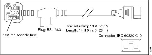
Figure 2-6 CAB-CRS4AC-US and Japan
Powering the Chassis Up or Down
The chassis does not have a single enable switch that powers the entire chassis and all its components up and down. (These switches are called enable switches because they enable the power supplies to produce output voltage and power). Most components on the chassis, such as the power supplies, MSCs, FPs, PLIMs, and fan trays can be removed or installed in the chassis while it is running.
Before you can power the chassis up, you must complete the following tasks:
Step 1 ![]() Install the appropriate power shelf for your system (see the "Installing a DC Power Shelf" section or the "Installing an AC Power Shelf" section).
Install the appropriate power shelf for your system (see the "Installing a DC Power Shelf" section or the "Installing an AC Power Shelf" section).
Step 2 ![]() Install the power supplies (see the "Installing a Power Supply" section).
Install the power supplies (see the "Installing a Power Supply" section).
Step 3 ![]() Install the route processor (RP) card (see the "Installing an RP or PRP Card" section).
Install the route processor (RP) card (see the "Installing an RP or PRP Card" section).
Step 4 ![]() Install the input power cables to the input power connectors on the rear of the chassis, and the other end (plug side) to the AC or DC power source.
Install the input power cables to the input power connectors on the rear of the chassis, and the other end (plug side) to the AC or DC power source.
Step 5 ![]() Activate your power source.
Activate your power source.
Step 6 ![]() Turn the two power shelf enable switches on the rear (SFC) side of the power shelf (see Figure 2-7) to the ON position.
Turn the two power shelf enable switches on the rear (SFC) side of the power shelf (see Figure 2-7) to the ON position.
Note ![]() The two enable switches on the rear (SFC) side of the AC power shelf (Figure 2-7) put the chassis in standby mode; in other words, they only power down the -54VDC output from the power supplies.
The two enable switches on the rear (SFC) side of the AC power shelf (Figure 2-7) put the chassis in standby mode; in other words, they only power down the -54VDC output from the power supplies.
Figure 2-7 AC Power Enable Switches

For an illustration of the DC power enable switches, see Figure 2-19.
Note ![]() All power cords must be unplugged from wall power to fully remove power from the chassis.
All power cords must be unplugged from wall power to fully remove power from the chassis.
DC Power Systems on the Cisco CRS 4-Slot Router
The Cisco CRS 4-slot line card chassis DC power shelf consists of two major components, as shown in Figure 2-8:
•![]() DC power input shelf (Cisco product number: CRS-4-DC-INPUT)
DC power input shelf (Cisco product number: CRS-4-DC-INPUT)
Figure 2-8 shows the power supplies installed in the DC power input shelf.
•![]() DC power input module (PIM) (Cisco product number: CRS-4-DC-PIM)
DC power input module (PIM) (Cisco product number: CRS-4-DC-PIM)
Figure 2-8 DC Power Shelf: DC Power Input Shelf and DC Power Input Module (PIM)
|
|
DC power input shelf |
|
Power input module (PIM) |
When installing the DC power shelf, these two components are mated to create the complete DC power shelf (see the "Installing a DC Power Shelf" section for details).
The Cisco CRS 4-slot line card chassis DC power system provides 4,000 watts to power the chassis. (To provide power redundancy, up to 8,000 watts are available.) Each DC-powered chassis contains four DC power supplies for 2N redundancy. The power input module (PIM) provides the input power connections. Note that each power connection has two cables: -48 VDC and return. The power input module (PIM), DC power input shelf, and the power supplies are field replaceable.
The Cisco CRS 4-slot line card chassis requires a total of four dedicated pairs of 60-A DC input power connections, one pair for each of the power supplies, to provide redundant DC power to the Cisco CRS 4-slot line card chassis midplane.
For full 2N redundancy, we recommend that you have two independent -48 VDC power sources to provide power to the Cisco CRS 4-slot line card chassis. Connect the two 60-A DC inputs on the left to one wiring block, and the two 60-A DC inputs on the right to the other wiring block.
DC Power Shelf Guidelines
At sites where the Cisco CRS 4-slot line card chassis is equipped with a DC power input shelf and power supplies, observe the following guidelines:
•![]() All power connection wiring should follow the rules and regulations in the National Electrical Code (NEC) and any local codes.
All power connection wiring should follow the rules and regulations in the National Electrical Code (NEC) and any local codes.
•![]() Each DC-input power entry module connection is rated at 60 A maximum. A dedicated, commensurately rated DC power source is required for each power supply connection.
Each DC-input power entry module connection is rated at 60 A maximum. A dedicated, commensurately rated DC power source is required for each power supply connection.
•![]() Each power supply requires one -48 VDC input, or four inputs for each power shelf (in which each input consists of a pair of positive and negative wires), and one power-shelf grounding wire.
Each power supply requires one -48 VDC input, or four inputs for each power shelf (in which each input consists of a pair of positive and negative wires), and one power-shelf grounding wire.
•![]() For DC power cables, we recommend that you use commensurately rated, high-strand-count copper wire cable. Each DC power supply requires one -48 VDC input, which means that there are two wires for each power supply, or eight total wires (four pairs) for each power shelf, plus the grounding wire. The length of the wires depends on the router's location. These wires are not available from Cisco Systems; they are available from any commercial vendor.
For DC power cables, we recommend that you use commensurately rated, high-strand-count copper wire cable. Each DC power supply requires one -48 VDC input, which means that there are two wires for each power supply, or eight total wires (four pairs) for each power shelf, plus the grounding wire. The length of the wires depends on the router's location. These wires are not available from Cisco Systems; they are available from any commercial vendor.
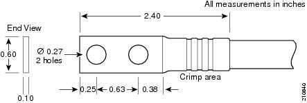
•![]() DC power cables must be terminated by cable lugs at the power-shelf end. The lugs should be dual hole and able to fit over M6 terminal studs at 0.625-in (15.88-mm) centers (for example, Panduit part number LCD2-14A-Q or equivalent) (see Figure 2-9).
DC power cables must be terminated by cable lugs at the power-shelf end. The lugs should be dual hole and able to fit over M6 terminal studs at 0.625-in (15.88-mm) centers (for example, Panduit part number LCD2-14A-Q or equivalent) (see Figure 2-9).
Figure 2-9 DC Power Cable Lug
Color Coding of the Source DC Power Cable
The color coding of the source DC power cable leads depends on the color coding of the site DC power source. Typically, green or green and yellow indicates that the cable is a ground cable. Because no color code standard exists for the source DC wiring, you must ensure that the power cables are connected to the DC-input power shelf terminal studs in the proper positive (+) polarity and negative (-) polarity.
DC Cable Polarity Labels
Sometimes, the source DC cable leads might have a positive (+) or a negative (-) label. This label is a relatively safe indication of the polarity, but you must verify the polarity by measuring the voltage between the DC cable leads. When making the measurement, the positive (+) lead and the negative (-) lead must always match the (+) and (-) labels on the power shelf.
Note ![]() When wiring the DC power shelf, be sure to attach the ground wire first. When removing the wiring, be sure to remove the ground wire last. The ground wire must be attached with a torque value of 30 in-lb. The power cables should also be attached with a torque value of 30 in-lb.
When wiring the DC power shelf, be sure to attach the ground wire first. When removing the wiring, be sure to remove the ground wire last. The ground wire must be attached with a torque value of 30 in-lb. The power cables should also be attached with a torque value of 30 in-lb.
Wiring Block on the PIM
Each wiring block on the power input module (PIM) contains four sets of terminals, two positive and two negative (see Figure 2-10). Each wiring block is covered by a plastic block cover that snaps onto the wiring block and is secured by a screw to a torque value of 50 in.-lb.
You must remove the block cover before you work with the wires.
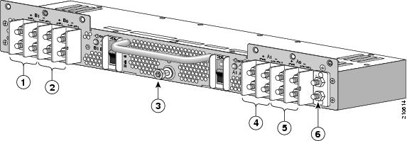
Figure 2-10 Power Input Module (PIM)
|
|
Power supply B1 wiring block |
|
Power supply A1 wiring block |
|
|
Power supply B0 wiring block |
|
Power supply A0 wiring block |
|
|
Power shelf coupling screw |
|
Ground lug nuts |
Input-Power-Present LEDs
The DC power Input-Power-Present LEDs provide a visual indication to service personnel that there is voltage present across the input terminal's connections (see Figure 2-11). The LED provides a warning to the service person that there is power present.
Note ![]() Power should be disconnected before servicing the input power connections. Always check for hazardous voltage with a multimeter device before servicing the router.
Power should be disconnected before servicing the input power connections. Always check for hazardous voltage with a multimeter device before servicing the router.
Figure 2-11 Input-Power-Present LEDs
The input-power-present LED starts to light up when the input voltage reaches 20 VDC; the LED gets brighter as voltage increases. The input-power-present LED is fully lit when the input voltage reaches 38 VDC.
Note ![]() If an input-power-present LED is not lit, check for: 1) the presence of voltage, and 2) the polarity of the corresponding wiring block.
If an input-power-present LED is not lit, check for: 1) the presence of voltage, and 2) the polarity of the corresponding wiring block.
DC Power Wire Characteristics
For signal degradation to be averted, a conductor must be large enough to prevent its impedance from creating a voltage drop equal to 2 percent of the reference voltage. Also, the gauge of the earth conductor must be equal to or larger then that of the -48 VDC (or -48 VDC return) conductor. This latter requirement is for safety. Full fault redundancy is achieved by having conductors of equal size for the protective earth ground and the -48 VDC return of the switch.
For site preparation, proper wire size and insulation must be selected. For a planned power distribution, calculation must be done prior to distribution to meet the proper voltage drop and temperature rise.
For wire gauges that prevent unacceptable voltage drops over different lengths of copper wire, see Table 2-3. For the resistance of 1000 feet of copper wire for each gauge of wire, see Table 2-4. These references are for planning purposes and might be further subject to local laws and practices.
Table 2-3 provides the gauges of wire needed for wire lengths and DC power currents. The units of measurement are in American wire gauge (AWG).
Note ![]() Table 2-3 and Table 2-4 are for reference; we recommend using at least 50 A of DC current and 6-gauge wire.
Table 2-3 and Table 2-4 are for reference; we recommend using at least 50 A of DC current and 6-gauge wire.
Table 2-4 provides the correlation between wire gauge and the resistance (in Ohms for each 1000 feet of wire) for copper wire.
Installing a DC Power Shelf
This section describes how to install a DC power shelf in the Cisco CRS 4-slot line card chassis.
The DC power shelf encloses four power supplies and the power distribution connections and wiring. The DC power input shelf is installed in the front of the chassis; the power input module (PIM) is installed in the rear of the chassis.
We recommend that you have two separate, redundant -48 VDC power battery sources to provide power to the Cisco CRS 4-slot line card chassis. Connect the two input pair 60-A DC inputs on the left to one -48 VDC power source, and the input pair 60-A DC inputs on the right to the other -48 VDC power source.
Sequence of Tasks
The sequence of tasks required to install the DC power shelf is:
1. ![]() Remove the rear power access panels.
Remove the rear power access panels.
2. ![]() Install the DC power input module (PIM).
Install the DC power input module (PIM).
3. ![]() Install the DC power input shelf.
Install the DC power input shelf.
4. ![]() Mate and secure the power input module to the DC power input shelf.
Mate and secure the power input module to the DC power input shelf.
5. ![]() Connect the grounding cable and the power input cables.
Connect the grounding cable and the power input cables.
6. ![]() Install the DC power supplies.
Install the DC power supplies.
Prerequisites
Power down the Cisco CRS 4-slot line card chassis.

Tip ![]() We recommend that you do this procedure with the line card chassis mounted in a rack with sufficient space for bottom and side access to the screws.
We recommend that you do this procedure with the line card chassis mounted in a rack with sufficient space for bottom and side access to the screws.
Required Tools and Equipment
You need the following tools and parts to perform this task:
•![]() ESD-preventive wrist strap
ESD-preventive wrist strap
•![]() Medium flat-blade screwdriver
Medium flat-blade screwdriver
•![]() Number 1 Phillips screwdriver
Number 1 Phillips screwdriver
•![]() Number 2 Phillips screwdriver
Number 2 Phillips screwdriver
•![]() 5-mm Allen wrench
5-mm Allen wrench
•![]() 10-mm hex socket wrench
10-mm hex socket wrench
•![]() DC power input shelf (Cisco product number: CRS-4-DC-INPUT)
DC power input shelf (Cisco product number: CRS-4-DC-INPUT)
•![]() DC power input module (PIM) (Cisco product number: CRS-4-DC-PIM)
DC power input module (PIM) (Cisco product number: CRS-4-DC-PIM)
•![]() DC power supplies (Cisco product number: CRS-4-DC-SUPPLY)
DC power supplies (Cisco product number: CRS-4-DC-SUPPLY)
Note ![]() This procedure assumes that the Cisco CRS 4-slot line card chassis is already mounted in a rack with sufficient room to access the sides and the bottom of the chassis.
This procedure assumes that the Cisco CRS 4-slot line card chassis is already mounted in a rack with sufficient room to access the sides and the bottom of the chassis.
Steps
To install the DC power shelf, follow these steps:
Step 1 ![]() Attach the ESD-preventive wrist strap to your wrist and connect its leash to one of the ESD connection sockets on the front (PLIM) side of the chassis or a bare metal surface on the chassis.
Attach the ESD-preventive wrist strap to your wrist and connect its leash to one of the ESD connection sockets on the front (PLIM) side of the chassis or a bare metal surface on the chassis.
Step 2 ![]() If the AC power shelf is currently installed, remove it from the front of the chassis. (For details, see the "Removing an AC Power Shelf" section.)
If the AC power shelf is currently installed, remove it from the front of the chassis. (For details, see the "Removing an AC Power Shelf" section.)
Removing the Rear Power Access Panels
Before you can install the power input module, you must remove the rear power access panels.
Step 3 ![]() From the rear of the chassis, use a medium Phillips screwdriver to remove the rear power access panels (located on the bottom right and bottom left rear of the chassis). Remove the screws shown in Figure 2-12.
From the rear of the chassis, use a medium Phillips screwdriver to remove the rear power access panels (located on the bottom right and bottom left rear of the chassis). Remove the screws shown in Figure 2-12.
Tip ![]() One screw on each side is located under the chassis (as shown in Figure 2-12). To access this screw safely, the chassis must be in a rack with adequate space below the chassis.
One screw on each side is located under the chassis (as shown in Figure 2-12). To access this screw safely, the chassis must be in a rack with adequate space below the chassis.
Figure 2-12 Removing the Rear Power Access Panels

Step 4 ![]() Unscrew the coupling screw from each panel with a medium flat-blade screwdriver. Set aside the access panels and their screws.
Unscrew the coupling screw from each panel with a medium flat-blade screwdriver. Set aside the access panels and their screws.
Note ![]() You will need these screws later when you install the power input module (PIM).
You will need these screws later when you install the power input module (PIM).
Installing the DC Power Input Module
Step 5 ![]() From the rear of the chassis, insert the DC power input module (PIM) into the open power bay (see Figure 2-13).
From the rear of the chassis, insert the DC power input module (PIM) into the open power bay (see Figure 2-13).
Note ![]() The PIM weighs 6.5 lb (2.9 kg).
The PIM weighs 6.5 lb (2.9 kg).
Figure 2-13 Inserting the DC Power Input Module (PIM)

Step 6 ![]() Reinsert the No. 2 Phillips screws taken from the rear power access panels into their respective holes: one on each side, three in front, and one underneath the chassis.
Reinsert the No. 2 Phillips screws taken from the rear power access panels into their respective holes: one on each side, three in front, and one underneath the chassis.
Installing the DC Power Input Shelf
Step 7 ![]() Go to the front of the chassis. To install the DC power input shelf, follow these steps:
Go to the front of the chassis. To install the DC power input shelf, follow these steps:
a. ![]() To prepare the chassis for installing the DC power input shelf, remove the inlet grille from the bottom of the chassis (for the procedure, see the "Removing the Inlet Grille" section).
To prepare the chassis for installing the DC power input shelf, remove the inlet grille from the bottom of the chassis (for the procedure, see the "Removing the Inlet Grille" section).
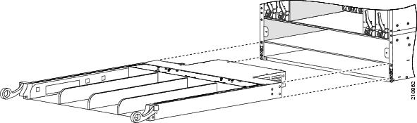
b. ![]() Holding the DC power input shelf underneath with one hand and steadying it with the other, lift the DC power input shelf up and slide it part way into the power shelf slot on the front (PLIM) side of the chassis. Be sure to center the DC power input shelf in the slot when you slide it in (see Figure 2-14).
Holding the DC power input shelf underneath with one hand and steadying it with the other, lift the DC power input shelf up and slide it part way into the power shelf slot on the front (PLIM) side of the chassis. Be sure to center the DC power input shelf in the slot when you slide it in (see Figure 2-14).
c. ![]() Slide the DC power input shelf fully into the chassis. Be sure that the lever handles are aligned with the lever handle catches on the chassis casing.
Slide the DC power input shelf fully into the chassis. Be sure that the lever handles are aligned with the lever handle catches on the chassis casing.
d. ![]() To lock the power input shelf into position, lift the lever handles up.
To lock the power input shelf into position, lift the lever handles up.
Figure 2-14 Inserting the DC Power Input Shelf
Securing the PIM to the DC Power Input Shelf
Step 8 ![]() Go to the rear of the chassis. To mate the PIM to the DC power input shelf, push the PIM firmly but carefully into the power input shelf.
Go to the rear of the chassis. To mate the PIM to the DC power input shelf, push the PIM firmly but carefully into the power input shelf.
Step 9 ![]() To secure the input power module connections to the power input shelf, use a 5-mm Allen wrench to tighten the power shelf coupling screw into the DC power input shelf (see Figure 2-15).
To secure the input power module connections to the power input shelf, use a 5-mm Allen wrench to tighten the power shelf coupling screw into the DC power input shelf (see Figure 2-15).
Figure 2-15 Power Shelf Coupling Screw

|
|
Power shelf coupling screw |
|
Ground lug nuts |
Connecting the Grounding Cable and Power Input Cables
Step 10 ![]() On the PIM, use a 10-mm hex socket wrench to connect the grounding cable (see item 2 in Figure 2-15).
On the PIM, use a 10-mm hex socket wrench to connect the grounding cable (see item 2 in Figure 2-15).
Note ![]() When wiring the power shelf, be sure to attach the ground wire first. When removing the wiring, be sure to remove the ground wire last. The ground wire must be attached with a torque value of 30 in-lb.
When wiring the power shelf, be sure to attach the ground wire first. When removing the wiring, be sure to remove the ground wire last. The ground wire must be attached with a torque value of 30 in-lb.
Step 11 ![]() On the PIM, use a 10-mm hex socket wrench to hook up the DC input power cables. Connect the four 60 A DC cables (two cables per input) on the left to one wiring block, and the four 60A DC cables on the right to the other wiring block (see Figure 2-16).
On the PIM, use a 10-mm hex socket wrench to hook up the DC input power cables. Connect the four 60 A DC cables (two cables per input) on the left to one wiring block, and the four 60A DC cables on the right to the other wiring block (see Figure 2-16).
Note ![]() The DC input power cables should also be attached with a torque value of 30 in-lb.
The DC input power cables should also be attached with a torque value of 30 in-lb.
Color Coding of the Source DC Power Cable. The color coding of the source DC power cable leads depends on the color coding of the site's DC power source. Typically, green or green and yellow indicates that the cable is a ground cable. Because no color code standard exists for the source DC wiring, you must ensure that the power cables are connected to the DC-input power shelf terminal studs in the proper positive (+) polarity and negative (-) polarity.
DC Cable Polarity Labels. Sometimes, the source DC cable leads might have a positive (+) or a negative (-) label. This label is a relatively safe indication of the polarity, but you must verify the polarity by measuring the voltage between the DC cable leads. When making the measurement, the positive (+) lead and the negative (-) lead must always match the (+) and (-) labels on the power shelf.
Figure 2-16 DC Power Shelf Cable Cabling

Step 12 ![]() Reattach both wiring block covers (see Figure 2-16).
Reattach both wiring block covers (see Figure 2-16).
a. ![]() Snap the cover over the wiring block so that it snaps closed.
Snap the cover over the wiring block so that it snaps closed.
b. ![]() Use a number 1 Phillips screwdriver to tighten the capture screw.
Use a number 1 Phillips screwdriver to tighten the capture screw.
Note ![]() The wiring block covers can be oriented to route the wire cabling from the top or the bottom of the covers.
The wiring block covers can be oriented to route the wire cabling from the top or the bottom of the covers.
Installing the DC Power Supplies
Step 13 ![]() Go to the front of the chassis. Install the four DC power supplies into the power input shelf (see Figure 2-17). For details, see the "Installing a Power Supply" section.
Go to the front of the chassis. Install the four DC power supplies into the power input shelf (see Figure 2-17). For details, see the "Installing a Power Supply" section.
Note ![]() Each DC power supply weighs 4.5 lb (2 kg).
Each DC power supply weighs 4.5 lb (2 kg).
Figure 2-17 Installing DC Power Supplies

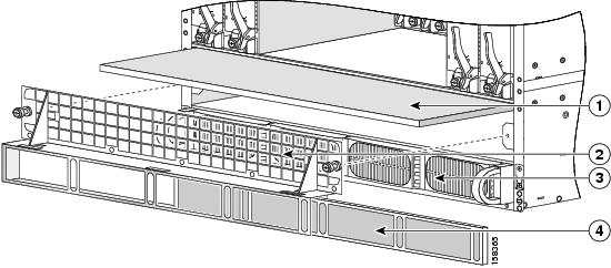
Step 14 ![]() Install the air filter (see Figure 2-18). For the procedure, see the "Installing the Chassis Air Filter" section.
Install the air filter (see Figure 2-18). For the procedure, see the "Installing the Chassis Air Filter" section.
Figure 2-18 Chassis Air Filter
|
|
Chassis air filter |
|
Power tray and power supplies |
|
|
Air intake grille |
|
Power tray air filter |
Step 15 ![]() Install the inlet grille. See the "Installing the Inlet Grille" section.
Install the inlet grille. See the "Installing the Inlet Grille" section.
Removing a DC Power Shelf
This section describes how to remove a DC power shelf from the Cisco CRS 4-slot line card chassis. The DC power shelf is comprised of both the DC power input shelf and the DC power input module (PIM). The DC power shelf encloses four power supplies and the power distribution connections and wiring blocks.
The DC power input shelf is in the front of the chassis; the power input module (PIM) is in the rear of the chassis.
Sequence of Tasks
The sequence of tasks required to remove the DC power shelf is as follows:
1. ![]() Bring down all power to the chassis.
Bring down all power to the chassis.
2. ![]() Disconnect the input power cables.
Disconnect the input power cables.
3. ![]() Disconnect the grounding cable.
Disconnect the grounding cable.
4. ![]() Remove the air intake (inlet) grille.
Remove the air intake (inlet) grille.
5. ![]() Remove all DC power supplies.
Remove all DC power supplies.
6. ![]() Remove the DC power input shelf.
Remove the DC power input shelf.
7. ![]() Remove the DC power input module (PIM).
Remove the DC power input module (PIM).
Prerequisites
Power down the Cisco CRS 4-slot line card chassis (as described in the steps below).
Required Tools and Equipment
You need the following tools and parts to perform this task:
•![]() ESD-preventive wrist strap
ESD-preventive wrist strap
•![]() Medium flat-blade screwdriver
Medium flat-blade screwdriver
•![]() Number 1 Phillips screwdriver
Number 1 Phillips screwdriver
•![]() Number 2 Phillips screwdriver
Number 2 Phillips screwdriver
•![]() 5-mm Allen wrench
5-mm Allen wrench
•![]() 10-mm hex socket wrench
10-mm hex socket wrench
Note ![]() This procedure assumes that the Cisco CRS 4-slot line card chassis is already mounted in a rack with sufficient room to access the sides and the bottom of the chassis.
This procedure assumes that the Cisco CRS 4-slot line card chassis is already mounted in a rack with sufficient room to access the sides and the bottom of the chassis.
Steps
To remove the DC power shelf, follow these steps:
Step 1 ![]() Attach the ESD-preventive wrist strap to your wrist and connect its leash to one of the ESD connection sockets on the front (PLIM) side of the chassis or a bare metal surface on the chassis.
Attach the ESD-preventive wrist strap to your wrist and connect its leash to one of the ESD connection sockets on the front (PLIM) side of the chassis or a bare metal surface on the chassis.
Bring Down All Power to the Chassis
Step 2 ![]() Power down the chassis:
Power down the chassis:
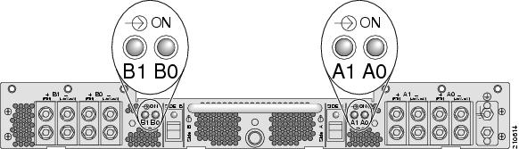
a. ![]() Go to the rear of the chassis. On the PIM, set both power shelf enable switches to OFF (see Figure 2-19). Now the system's boards and fans have no power.
Go to the rear of the chassis. On the PIM, set both power shelf enable switches to OFF (see Figure 2-19). Now the system's boards and fans have no power.
b. ![]() Unplug the DC power supplies.
Unplug the DC power supplies.
c. ![]() Disconnect input power from the customer source.
Disconnect input power from the customer source.
Figure 2-19 DC Power Shelf Enable Switches

|
|
DC power shelf enable switches |
Step 3 ![]() Remove both wiring block covers (see Figure 2-20).
Remove both wiring block covers (see Figure 2-20).
a. ![]() Use a number 1 Phillips screwdriver to loosen the capture screw.
Use a number 1 Phillips screwdriver to loosen the capture screw.
b. ![]() Snap off the cover over the wiring block.
Snap off the cover over the wiring block.
Disconnect the Input Power Cables and Grounding Cable
Step 4 ![]() Use a 10-mm hex socket wrench to disconnect the DC input power cables.
Use a 10-mm hex socket wrench to disconnect the DC input power cables.
Disconnect the four 60 A DC cables (two cables per input) on the left from one wiring block, and the four 60 A DC cables on the right from the other wiring block (see Figure 2-20).
Step 5 ![]() Use a 10-mm hex socket wrench to disconnect the grounding cable (see Figure 2-20).
Use a 10-mm hex socket wrench to disconnect the grounding cable (see Figure 2-20).
Figure 2-20 Removing Wiring Block Covers and DC Input Power Cables

|
|
Power shelf coupling screw |
|
Grounding lug nuts |
Step 6 ![]() With a 5-mm Allen wrench, loosen the power shelf coupling screw (see item 1 in Figure 2-20). This will allow you to remove the DC power input shelf from the chassis (as described below).
With a 5-mm Allen wrench, loosen the power shelf coupling screw (see item 1 in Figure 2-20). This will allow you to remove the DC power input shelf from the chassis (as described below).
Step 7 ![]() Go to the front of the chassis. Remove the inlet grille. For the procedure, see the "Removing the Inlet Grille" section.
Go to the front of the chassis. Remove the inlet grille. For the procedure, see the "Removing the Inlet Grille" section.
Step 8 ![]() Remove the four DC power supplies. For the procedure, see the "Removing a Power Supply" section.
Remove the four DC power supplies. For the procedure, see the "Removing a Power Supply" section.
Remove the DC Power Input Shelf
Step 9 ![]() While still in the front of the chassis, you can now remove the DC power input shelf. To remove the DC power input shelf, follow these steps:
While still in the front of the chassis, you can now remove the DC power input shelf. To remove the DC power input shelf, follow these steps:
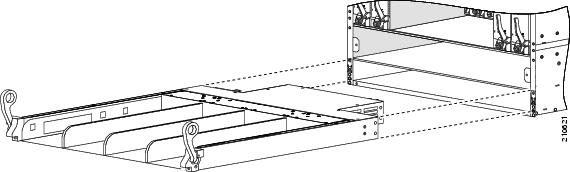
a. ![]() To unlock the power input shelf, pull the lever handles down (see Figure 2-21).
To unlock the power input shelf, pull the lever handles down (see Figure 2-21).
b. ![]() Holding the DC power input shelf underneath with one hand and steadying it with the other, lift the DC power input shelf up and slide it part way out of the power shelf slot.
Holding the DC power input shelf underneath with one hand and steadying it with the other, lift the DC power input shelf up and slide it part way out of the power shelf slot.
c. ![]() Slide the DC power input shelf fully out of the chassis. Set the power input shelf carefully aside.
Slide the DC power input shelf fully out of the chassis. Set the power input shelf carefully aside.
Figure 2-21 Removing the DC Power Input Shelf
Remove the DC Power Input Module (PIM)
Step 10 ![]() Go to the rear of the chassis. Remove the DC power input module (PIM).
Go to the rear of the chassis. Remove the DC power input module (PIM).
a. ![]() With a Number 2 Phillips screwdriver, remove the first set of eight screws—six screws in the front of the chassis, two on the outside right and left sides of the chassis (see Figure 2-22).
With a Number 2 Phillips screwdriver, remove the first set of eight screws—six screws in the front of the chassis, two on the outside right and left sides of the chassis (see Figure 2-22).
b. ![]() Remove the additional two screws underneath the chassis (one on the left side, one on the right side) (see Figure 2-22).
Remove the additional two screws underneath the chassis (one on the left side, one on the right side) (see Figure 2-22).
c. ![]() With one hand gripping the handle and one hand underneath the module, carefully remove the PIM from the chassis, then set it aside.
With one hand gripping the handle and one hand underneath the module, carefully remove the PIM from the chassis, then set it aside.
Figure 2-22 Removing the DC Power Input Module (PIM)
Installing an AC Power Shelf
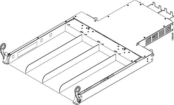
This section describes how to install an AC power shelf in the Cisco CRS 4-slot line card chassis. The power shelf encloses four power supplies and the power distribution connections and wiring. The AC power shelf is installed in the front (PLIM) side of the chassis.
The AC-powered chassis contains a single AC power shelf containing four AC power supplies. Each AC power supply converts input AC power to the -54 VDC used by the Cisco CRS 4-slot line card chassis.
The AC power shelf is configured for single-phase AC power supply wiring (two wires + ground), and is safety-rated at 110 to 240 VAC nominal, 50 to 60 Hz (4x) 11A.
For additional power details, see Cisco CRS Carrier Routing System 4-Slot Line Card Chassis System Description, or in this document, see "Cisco CRS 4-Slot Line Card Chassis System Specifications."
For complete information on regulatory compliance and safety, see Cisco CRS Carrier Routing System Regulatory Compliance and Safety Information.
Prerequisites
Remove the air intake grille from the bottom of the chassis.
Required Tools and Equipment
You need the following tools and parts to perform this task:
•![]() ESD-preventive wrist strap
ESD-preventive wrist strap
•![]() Medium flat-blade screwdriver
Medium flat-blade screwdriver
•![]() AC Power shelf (Cisco product number: CRS-4-AC-SHELF)
AC Power shelf (Cisco product number: CRS-4-AC-SHELF)
Figure 2-23 shows the AC power shelf.
Figure 2-23 AC Power Shelf
Steps
To install an AC power shelf, use Figure 2-23 as a reference and follow these steps:
Step 1 ![]() Attach the ESD-preventive wrist strap to your wrist and connect its leash to one of the ESD connection sockets on the front (PLIM) side of the chassis or a bare metal surface on the chassis.
Attach the ESD-preventive wrist strap to your wrist and connect its leash to one of the ESD connection sockets on the front (PLIM) side of the chassis or a bare metal surface on the chassis.
Step 2 ![]() Remove the air intake grille from the bottom of the chassis.
Remove the air intake grille from the bottom of the chassis.
Step 3 ![]() Holding the AC power shelf underneath with one hand and steadying it with the other, lift the shelf up and slide it partway into the power shelf slot on the front (PLIM) side of the chassis. Be sure to center the shelf in the slot when you slide it in.
Holding the AC power shelf underneath with one hand and steadying it with the other, lift the shelf up and slide it partway into the power shelf slot on the front (PLIM) side of the chassis. Be sure to center the shelf in the slot when you slide it in.
Step 4 ![]() Slide the AC power shelf fully into the chassis. Be sure that the lever handles are aligned with the lever handle catches on the chassis casing.
Slide the AC power shelf fully into the chassis. Be sure that the lever handles are aligned with the lever handle catches on the chassis casing.
Step 5 ![]() Lift the lever handles up to lock the tray into position.
Lift the lever handles up to lock the tray into position.
Step 6 ![]() Use the flat-blade screwdriver to turn the two captive screws that connect the rear of the chassis to the power shelf, and tighten them fully.
Use the flat-blade screwdriver to turn the two captive screws that connect the rear of the chassis to the power shelf, and tighten them fully.
What to Do Next
After performing this task, install the power supplies (see the "Installing a Power Supply" section), and replace any chassis cosmetic cover plates.
Removing an AC Power Shelf
This section describes how to remove an AC power shelf from the Cisco CRS 4-slot line card chassis. The AC power shelf encloses four power supplies and the power distribution connections and wiring. The AC power shelf is installed in the front (PLIM) side of the chassis. For more details on the power systems see the "About Installing and Removing the Power Components" section. For complete information on regulatory compliance and safety, see Cisco CRS Carrier Routing System Regulatory Compliance and Safety Information.
See Figure 2-23 for an illustration of the AC power shelf.
Prerequisites
Before performing this task, you must first remove the air intake grille from the bottom of the chassis, power down the chassis (see the "AC Power Supply Cord Illustrations and Plug Types" section), and detach the power cords.
Required Tools and Equipment
You need the following tools to perform this task:
•![]() ESD-preventive wrist strap
ESD-preventive wrist strap
•![]() Medium flat-blade screwdriver
Medium flat-blade screwdriver
Steps
To remove an AC power shelf, follow these steps:
Step 1 ![]() Attach the ESD-preventive wrist strap to your wrist and connect its leash to one of the ESD connection sockets on the front (PLIM) side of the chassis or a bare metal surface on the chassis.
Attach the ESD-preventive wrist strap to your wrist and connect its leash to one of the ESD connection sockets on the front (PLIM) side of the chassis or a bare metal surface on the chassis.
Step 2 ![]() Remove all four power supplies from the shelf you are removing. (See the "Removing a Power Supply" section.)
Remove all four power supplies from the shelf you are removing. (See the "Removing a Power Supply" section.)
Step 3 ![]() Remove the power cables from the power from the four power inlets.
Remove the power cables from the power from the four power inlets.
Step 4 ![]() While facing the rear (SFC) side of the chassis, use the screwdriver to loosen the two captive screws that connect the rear of the chassis to the power shelf by turning them counterclockwise.
While facing the rear (SFC) side of the chassis, use the screwdriver to loosen the two captive screws that connect the rear of the chassis to the power shelf by turning them counterclockwise.
Step 5 ![]() Pull the lever handles down with both hands and slide the AC power shelf partway from the slot in the chassis.
Pull the lever handles down with both hands and slide the AC power shelf partway from the slot in the chassis.
Step 6 ![]() Placing one hand underneath the AC power shelf and pulling on it and steadying it with the other hand, slide the shelf completely from the chassis. (If attached, be sure to thread the power cable through the chassis carefully.)
Placing one hand underneath the AC power shelf and pulling on it and steadying it with the other hand, slide the shelf completely from the chassis. (If attached, be sure to thread the power cable through the chassis carefully.)
Step 7 ![]() Set the AC power shelf carefully aside.
Set the AC power shelf carefully aside.
What to Do Next
After performing this task, you may install a replacement power shelf (see the "Installing an AC Power Shelf" section), install the power supplies (see the "Installing a Power Supply" section), and replace any front chassis cosmetic covers.
Installing a Power Supply
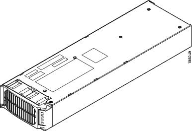
This section describes how to install an AC or DC power supply in the Cisco CRS 4-slot power shelf. The AC power supply converts facility AC power into the DC power necessary to power the cards and modules in the chassis. Each AC and DC power supply has its own pair of cooling fans, which draws air through the power supply.
For complete information on regulatory compliance and safety, see Cisco CRS Carrier Routing System Regulatory Compliance and Safety Information.
Figure 2-24 shows a power supply.
Figure 2-24 Power Supply
Prerequisites
Before performing this task, make sure that the power shelf has been installed (see the "Installing an AC Power Shelf" section or the "Installing a DC Power Shelf" section); remove any cosmetic covers.
Required Tools and Equipment
You need the following tools and part to perform this task:
•![]() ESD-preventive wrist strap
ESD-preventive wrist strap
•![]() Power supply
Power supply
Steps
To install a power supply, follow these steps:
Step 1 ![]() Attach the ESD-preventive wrist strap to your wrist and connect its leash to one of the ESD connection sockets on the front (PLIM) side of the chassis or a bare metal surface on the chassis.
Attach the ESD-preventive wrist strap to your wrist and connect its leash to one of the ESD connection sockets on the front (PLIM) side of the chassis or a bare metal surface on the chassis.
Step 2 ![]() Using two hands to support and guide the power supply, slide it partway into the power tray on the front (PLIM) side of the chassis.
Using two hands to support and guide the power supply, slide it partway into the power tray on the front (PLIM) side of the chassis.
Step 3 ![]() Make sure that the power supply door grille is in the open position (see Figure 2-25).
Make sure that the power supply door grille is in the open position (see Figure 2-25).
Figure 2-25 Power Supply Door Grille in Open Position

|
|
Power supply door grille |
|
Power supply door latch |
Step 4 ![]() Slide the power supply into the power shelf until the connector on the back of the module meets the connector on the backplane of the AC or DC power shelf.
Slide the power supply into the power shelf until the connector on the back of the module meets the connector on the backplane of the AC or DC power shelf.
Step 5 ![]() Close the power supply door grille to seat the power supply fully against the AC or DC power shelf. Make sure that the power supply door grille latch clicks into place.
Close the power supply door grille to seat the power supply fully against the AC or DC power shelf. Make sure that the power supply door grille latch clicks into place.
Tip ![]() The power supply door can be latched while it is still outside of the power shelf; if that occurs, the power supply will not function according to specification. To ensure proper functionality, the power supply door must be latched only after the power supply is fully engaged into the AC power shelf.
The power supply door can be latched while it is still outside of the power shelf; if that occurs, the power supply will not function according to specification. To ensure proper functionality, the power supply door must be latched only after the power supply is fully engaged into the AC power shelf.
What to Do Next
After performing this task, you may connect the power shelf to the power source (see the "About Installing and Removing the Power Components" section, replace any front cosmetic covers, and power up the chassis (see the "AC Power Supply Cord Illustrations and Plug Types" section).
Removing a Power Supply
This section describes how to remove a power supply in the Cisco CRS 4-slot line card chassis. The power supplies can be an AC or DC power supplies (however, mixed types are not permitted). The AC power supply converts facility AC power into the DC power necessary to power the cards and modules in the chassis. Each AC power supply has its own pair of cooling fans, which draws air through the power supply.
For complete information on regulatory compliance and safety, see Cisco CRS Carrier Routing System Regulatory Compliance and Safety Information.
See Figure 2-24 for an illustration of a power supply.
Prerequisites
Before operating the power shelf ejectors and removing the power shelf, take the following precautions:
•![]() For an AC power shelf, ensure that the rear panel fasteners are disengaged.
For an AC power shelf, ensure that the rear panel fasteners are disengaged.
•![]() For a DC power shelf, unlock the power input shelf by pulling the lever handles down.
For a DC power shelf, unlock the power input shelf by pulling the lever handles down.
•![]() Disconnect the input power cables.
Disconnect the input power cables.
•![]() Remove the air intake (inlet) grille.
Remove the air intake (inlet) grille.
Required Tools and Equipment
You need the following tools to perform this task:
•![]() ESD-preventive wrist strap
ESD-preventive wrist strap
Steps
To remove a power supply, follow these steps:
Step 1 ![]() Attach the ESD-preventive wrist strap to your wrist and connect its leash to one of the ESD connection sockets on the front (PLIM) side of the chassis or a bare metal surface on the chassis.
Attach the ESD-preventive wrist strap to your wrist and connect its leash to one of the ESD connection sockets on the front (PLIM) side of the chassis or a bare metal surface on the chassis.
Step 2 ![]() To unseat the power supply from the power shelf connector, unlatch the power supply door grille latch and open it completely. See Figure 2-25 for an illustration of the power supply grille and door latch.
To unseat the power supply from the power shelf connector, unlatch the power supply door grille latch and open it completely. See Figure 2-25 for an illustration of the power supply grille and door latch.
Note ![]() The power supply fans may continue to turn at high speed for a few seconds after they are unseated from the power shelf.
The power supply fans may continue to turn at high speed for a few seconds after they are unseated from the power shelf.
Step 3 ![]() Grasp the power supply door grille and gently pull the power supply halfway from the bay.
Grasp the power supply door grille and gently pull the power supply halfway from the bay.
Step 4 ![]() Use your free hand to support the power supply while you slide the power supply completely from the bay, then set the power supply safely aside.
Use your free hand to support the power supply while you slide the power supply completely from the bay, then set the power supply safely aside.
What to Do Next
After performing this task, you may install a new power supply, if needed (see the "Installing a Power Supply" section), and replace any front cosmetic covers.
 Feedback