- Preface
- Overview
- Installing and Removing Power Components
- Installing and Removing Air Circulation Components
- Installing and Removing Fabric Cards and Card Components
- Installing and Removing Exterior Cosmetic Components
- Upgrading Chassis Components
- Cisco CRS-1 Carrier Routing System Fabric Card Chassis Specifications
- Product IDs
- Upgrading the Inlet Grille Screen
- Removing the Lower Grille
- Removing the Currently Installed Lower Grille Frame Assembly
- Installing the New Lower Grille Screen and Frame Assembly
- Installing the Rear Vertical Cable Troughs and Cutout Assembly
Upgrading Chassis Components
This chapter provides instructions on how to upgrade chassis components on the Cisco CRS Carrier Routing System Fabric Card Chassis.
This chapter presents the following topics:
- Upgrading the Inlet Grille Screen
- Removing the Lower Grille
- Removing the Currently Installed Lower Grille Frame Assembly
- Installing the New Lower Grille Screen and Frame Assembly
- Installing the Rear Vertical Cable Troughs and Cutout Assembly
- Upgrading the Lower Horizontal Cable Guide
- Upgrading the Upper Horizontal Cable Guide
Upgrading the Inlet Grille Screen
To ensure protection against debris getting through the lower grille and into the chassis bay, Cisco Systems provides a screen that you can install behind the lower grille.
This section describes how to install the new lower grille screen in the FCC. To install the lower grille screen kit (CRS-FCC-SCRN-KIT) as an update to an existing system, you must:
- Remove the lower grille from the front (SFC) side of the chassis.
- Remove the lower grille frame assembly that is currently installed.
- Install the new lower grille screen and frame assembly.
- Re-install the lower grille on the front (SFC) side of the chassis.
Required Tools and Equipment
You need the following tools and parts to perform this task:
- 8 in. long number 1 Phillips screwdriver—magnetic head preferable
-
Lower grille screen and frame assembly
- Lower grille screen kit (Cisco product number: CRS-FCC-SCRN-KIT)
Removing the Lower Grille
This section describes how to remove the lower grille from the front (SFC) side of the FCC.
Prerequisites
There are no prerequisites for this task.
Steps
To remove the lower grille from your FCC, perform the following steps:
1. Remove the lower grille by unsnapping the top portion from the ball stud snaps (see #task_1052855/fig_1052863).
2. Rotate the grille toward you on its hook hanger brackets, then lift it clear of the support, and set it carefully aside for later use.
DETAILED STEPS
| Step 1 | Remove the
lower grille by unsnapping the top portion from the ball stud snaps (see
#task_1052855/fig_1052863).

| ||||
| Step 2 | Rotate the grille toward you on its hook hanger brackets, then lift it clear of the support, and set it carefully aside for later use. |
Removing the Currently Installed Lower Grille Frame Assembly
Once the lower grille has been removed, you must remove the currently installed lower grille frame assembly from the chassis.
Prerequisites
Before performing this task, ensure that the lower grille has been removed from the front (SFC) side of the chassis. See the Removing the Lower Grille for more information.
Steps
To remove the currently installed lower grille frame assembly, perform the following steps:
1. Use the Phillips screwdriver to unscrew the four captive screws, two on each side, that attach the lower grille frame assembly to the chassis. See #task_1052895/fig_1052902.
2. Rotate the assembly forward, lift it away from the chassis, and set it aside.
DETAILED STEPS
| Step 1 | Use the
Phillips screwdriver to unscrew the four captive screws, two on each side, that
attach the lower grille frame assembly to the chassis. See
#task_1052895/fig_1052902.

| ||
| Step 2 | Rotate the assembly forward, lift it away from the chassis, and set it aside. |
Installing the New Lower Grille Screen and Frame Assembly
This section describes how to install the lower grille screen and frame assembly in the chassis.
In this task, you must first remove the lower grille screen from the frame, because the screws that attach the frame assembly to the chassis are inboard of the screen—that is, the new screen is shipped already installed into the new frame assembly, but you cannot attach the new frame to the chassis until you remove the screen first. When the new frame assembly is installed in the chassis, you can reinstall the lower grille screen into the new frame.
Prerequisites
Before performing this task, ensure that the original lower grille and lower grille frame assembly have been removed. See the c_Removing_the_Lower_Grille_1054251.xml#con_1054251 and the c_Removing_the_Currently_Installed_Lower_Grille_Frame_Assembly_1052881.xml#con_1052881 for more information.
Steps
To install the new lower grille screen and frame assembly, perform the following steps:
1. Using the Phillips screwdriver, loosen the four captive screws, two on each side, that secure the lower grille screen to its frame assembly; then carefully set the screen aside. See #task_1052919/fig_1052931.
2. Attach the frame assembly to the chassis (see #task_1052919/fig_1052931) by aligning the four screws, two on each side, on the frame to the screw holes on the chassis and tightening them with the screwdriver.
3. To reattach the lower grille screen (see #task_1052919/fig_1052931) to the frame assembly, align the four captive screws on the screen to the screw holes on the frame assembly and tighten with the screwdriver.
4. Attach the lower grille to the chassis by carefully inserting the tabs on the grille into the hook hanger brackets. See #task_1052919/fig_1054480.
5. Press the lower grille firmly until it snaps onto the ball stud snaps. See #task_1052919/fig_1054480.
DETAILED STEPS
| Step 1 | Using the Phillips screwdriver, loosen the four captive screws, two on each side, that secure the lower grille screen to its frame assembly; then carefully set the screen aside. See #task_1052919/fig_1052931. | ||||
| Step 2 | Attach the
frame assembly to the chassis (see
#task_1052919/fig_1052931)
by aligning the four screws, two on each side, on the frame to the screw holes
on the chassis and tightening them with the screwdriver.

| ||||
| Step 3 | To reattach the lower grille screen (see #task_1052919/fig_1052931) to the frame assembly, align the four captive screws on the screen to the screw holes on the frame assembly and tighten with the screwdriver. | ||||
| Step 4 | Attach the lower grille to the chassis by carefully inserting the tabs on the grille into the hook hanger brackets. See #task_1052919/fig_1054480. | ||||
| Step 5 | Press the lower
grille firmly until it snaps onto the ball stud snaps. See
#task_1052919/fig_1054480.
|
Installing the Rear Vertical Cable Troughs and Cutout Assembly
This section describes how to remove the vertical troughs from the rear of the FCC, and replace with the new vertical cable troughs and cutout assembly.
To upgrade the rear vertical cable troughs, you must:
- Remove the doors, lower bezel and upper grille from the rear (OIM) side of the chassis.
- Remove the currently installed vertical cable troughs.
- Install the new vertical cable troughs.
- Install the cable pass-through accessory plates on the new vertical cable troughs.
- Re-install the doors, lower bezel and upper grille on the rear (OIM) side of the chassis.
- Upgrading the Currently Installed Vertical Cable Troughs
- Installing the Cable Pass-through Accessory Plates
Upgrading the Currently Installed Vertical Cable Troughs
If you are installing the cable troughs with cutout assembly as an update to an existing system, the currently installed vertical trough must be removed from the chassis before the new vertical cable trough can be installed.
Prerequisites
Before performing this task, you must first remove the rear (OIM) side exterior doors, rear lower bezel, and rear upper grille. See the b-crs-16slot-installation-guide_chapter_0101.html#con_1051856 for more information.
Undo all velcro and carefully move the existing cables to either the inside or outside of the existing vertical cable trough (whichever is easier). Carefully pull slack, if required.
 Caution | Do NOT disconnect cables from the chassis during the vertical cable trough upgrade procedure. |
Required Tools and Equipment
You need the following tools and parts to perform this task:
- 8-in. long number 1 Phillips screwdriver—magnetic head preferable
- Cable management retrofit kit (Cisco product number: CRS-FCC-CM-RETRO=)
Steps
To replace the vertical trough on the FCC, perform the following steps:
1. Remove the mounting screws that attach the upper, middle and lower horizontal cable guides to the vertical cable troughs (left and right sides of chassis).
2. Remove the five mounting screws that attach the upper horizontal cable guide to the chassis and remove upper cable guide completely. See #task_1057784/fig_1064266.
3. Remove the rear vertical cable troughs (see #task_1057784/fig_1061705)—one right and one left— from the rear of the chassis:
4. If you plan to upgrade the lower horizontal cable guide, remove the five mounting screws that attach the lower horizontal cable guide to the chassis and remove lower cable guide completely. Replace with new lower horizontal cable guide with spools, by installing the four screws that attach the cable guide to the chassis. See the c_Upgrading_the_Lower_Horizontal_Cable_Guide_1053088.xml#con_1053088 for more information.
5. Attach the rear vertical cable troughs —one right and one left—to the rear of the chassis (as shown in #task_1057784/fig_1061705) by i nserting the 10 M4x14-mm flat head screws (5 on each side) and using the screwdriver to fasten the screws to attach the cable troughs firmly to the chassis.
6. Install the mounting screws that attach the upper horizontal cable guide to the chassis. See #task_1057784/fig_1062060.
7. Re-install the mounting screws that attach the lower, middle and upper horizontal cable guides to the vertical cable troughs (left and right sides of chassis).
DETAILED STEPS
| Step 1 | Remove the
mounting screws that attach the upper, middle and lower horizontal cable guides
to the vertical cable troughs (left and right sides of chassis).
#task_1057784/fig_1064266 shows the upper horizontal cable guide. 
#task_1057784/fig_1064783 shows the mid-chassis horizontal cable guide. 
#task_1057784/fig_1064820 shows the lower horizontal cable guide. 
| ||||||||||||||
| Step 2 | Remove the five mounting screws that attach the upper horizontal cable guide to the chassis and remove upper cable guide completely. See #task_1057784/fig_1064266. | ||||||||||||||
| Step 3 | Remove the rear
vertical cable troughs (see
#task_1057784/fig_1061705)—one
right and one left— from the rear of the chassis:
| ||||||||||||||
| Step 4 | If you plan to upgrade the lower horizontal cable guide, remove the five mounting screws that attach the lower horizontal cable guide to the chassis and remove lower cable guide completely. Replace with new lower horizontal cable guide with spools, by installing the four screws that attach the cable guide to the chassis. See the c_Upgrading_the_Lower_Horizontal_Cable_Guide_1053088.xml#con_1053088 for more information. | ||||||||||||||
| Step 5 | Attach the rear
vertical cable troughs —one right and one left—to the rear of the chassis (as
shown in
#task_1057784/fig_1061705)
by i nserting the 10 M4x14-mm flat head screws (5 on each side) and using the
screwdriver to fasten the screws to attach the cable troughs firmly to the
chassis.
 | ||||||||||||||
| Step 6 | Install the
mounting screws that attach the upper horizontal cable guide to the chassis.
See
#task_1057784/fig_1062060.
| ||||||||||||||
| Step 7 | Re-install the mounting screws that attach the lower, middle and upper horizontal cable guides to the vertical cable troughs (left and right sides of chassis). |
Installing the Cable Pass-through Accessory Plates
Depending on the size of the installation, and the number and type of cables being used, the body of the chassis may become overcrowded and unable to accommodate all of the required cables. To resolve this, you can install pass-through accessory plates to allow cables be guided outside the vertical trough.
System growth and cable type will determine whether cable pass-through accessory plates are required to be installed.
- If the chassis is part of a multishelf system with vertical cabling, cable pass-through accessory plates are not required to be installed.
- If the chassis is part of a multishelf system with horizontal cabling, cable-pass-through accessory plates are required to be installed.
- If riser cable is installed on the chassis, cable-pass-through accessory plates are required to be installed.
Prerequisites
Before performing this task, you must first ensure that the doors have been removed from the rear (OIM) side of the chassis and that the vertical troughs with cut-out plates have been installed. See the “Removing the Rear Exterior Doors” section on page 5-36 and the c_Upgrading_the_Currently_Installed_Vertical_Cable_Troughs_1052948.xml#con_1052948 for more information.
Steps
 Note | If you do not plan to route existing cables through the cutouts on the vertical cable troughs, then you are only required to perform #task_1052997/_1053046, #task_1052997/_1053059 and #task_1052997/_1057913. |
To attach the cable pass-through accessory plates to the vertical troughs, perform the following steps:
1. Remove the hinge keepers and the door hinges from the rear of the chassis (left and right side). See#task_1052997/fig_1053019. Optional—only required if you are going to route existing cables through the cutouts.
2. Remove the blank plates by unscrewing the four screws on each one. See #task_1052997/fig_1053048.
3. Attach the inner cut-out plates, as shown in #task_1052997/fig_1053061, using the four screws provided. See #task_1052997/fig_1053067.
4. Route the cables through the opening. Reposition cables in the vertical cable trough. Ensure that cables are secured with velcro on upper and middle horizontal cable management brackets.Optional—only required if you are going to route existing cables through the cutouts.
5. Attach the outer cut-out panel using the screws provided. See #task_1052997/fig_1053078.
6. Re-install the hinge keepers and door hinges. Optional—only required if you are going to route existing cables through the cutouts.
7. Re-install the doors on the rear (OIM) side of the chassis. Optional—only required if you are going to route existing cables through the cutouts.
DETAILED STEPS
| Step 1 | Remove the
hinge keepers and the door hinges from the rear of the chassis (left and right
side). See#task_1052997/fig_1053019.
Optional—only required if you are going to route existing cables through the
cutouts.

| ||||||||
| Step 2 | Remove the
blank plates by unscrewing the four screws on each one. See
#task_1052997/fig_1053048.
 | ||||||||
| Step 3 | Attach the
inner cut-out plates, as shown in
#task_1052997/fig_1053061,
using the four screws provided. See
#task_1052997/fig_1053067.
  | ||||||||
| Step 4 | Route the cables through the opening. Reposition cables in the vertical cable trough. Ensure that cables are secured with velcro on upper and middle horizontal cable management brackets.Optional—only required if you are going to route existing cables through the cutouts. | ||||||||
| Step 5 | Attach the
outer cut-out panel using the screws provided. See
#task_1052997/fig_1053078.
 | ||||||||
| Step 6 | Re-install the hinge keepers and door hinges. Optional—only required if you are going to route existing cables through the cutouts. | ||||||||
| Step 7 | Re-install the doors on the rear (OIM) side of the chassis. Optional—only required if you are going to route existing cables through the cutouts. |
Upgrading the Lower Horizontal Cable Guide
If you are installing the new lower horizontal cable guide as an update to an existing system, the currently installed lower horizontal cable guide must be removed from the chassis before the new lower horizontal cable guide can be installed.
Note | The lower horizontal cable guide should be replaced as part of the vertical cable trough replacement procedure described in the c_Upgrading_the_Currently_Installed_Vertical_Cable_Troughs_1052948.xml#con_1052948. |
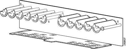
#con_1053088/fig_1058370 shows the new lower horizontal cable guide.
Required Tools and Equipment
You need the following tools and parts to perform this task:
- 8-in. long number 1 Phillips screwdriver—magnetic head preferable
- Cable management retrofit kit (Cisco product number: CRS-FCC-CM-RETRO=)
Prerequisites
Before performing this task, you must first open the doors on the rear (OIM) side of the chassis.
Steps
To upgrade the lower horizontal cable guide, perform the following steps:
1. Remove the nine screws that attach the horizontal cable guide to the chassis as shown in #task_1053095/fig_1053103. Four screws attach the cable guide to the vertical trough flanges, and five screws attach the cable guide to the rear of the chassis.
2. Pull lower horizontal cable guide straight out and set aside. See #task_1053095/fig_1053103.
3. Slide the new lower horizontal cable guide into the chassis.
4. Attach the rear lower horizontal cable guide to the chassis by inserting four longer Phillips head screws through the holes in the face of the cable guide and into the chassis and tighten. See #task_1053095/fig_1055163.
5. Insert the four short screws (two on each side) that attach the bracket to the vertical cable trough support flange and tighten. See #task_1053095/fig_1055163.
6. Close the doors on the rear (OIM) side of the chassis.
DETAILED STEPS
| Step 1 | Remove the nine screws that attach the horizontal cable guide to the chassis as shown in #task_1053095/fig_1053103. Four screws attach the cable guide to the vertical trough flanges, and five screws attach the cable guide to the rear of the chassis. | ||||
| Step 2 | Pull lower
horizontal cable guide straight out and set aside. See
#task_1053095/fig_1053103.
 | ||||
| Step 3 | Slide the new lower horizontal cable guide into the chassis. | ||||
| Step 4 | Attach the rear lower horizontal cable guide to the chassis by inserting four longer Phillips head screws through the holes in the face of the cable guide and into the chassis and tighten. See #task_1053095/fig_1055163. | ||||
| Step 5 | Insert the four
short screws (two on each side) that attach the bracket to the vertical cable
trough support flange and tighten. See
#task_1053095/fig_1055163.
| ||||
| Step 6 | Close the doors on the rear (OIM) side of the chassis. |
Upgrading the Upper Horizontal Cable Guide
If you are installing the new upper horizontal cable guide as an update to an existing system, the currently installed upper horizontal cable guide must be removed from the chassis before the new upper horizontal cable guide can be installed.
Note | The upper horizontal cable guide should be replaced as part of the vertical cable trough replacement procedure described in the c_Upgrading_the_Currently_Installed_Vertical_Cable_Troughs_1052948.xml#con_1052948. |
Note | The new upper horizontal cable guide contains additional slots. |
Required Tools and Equipment
You need the following tools and parts to perform this task:
- 8-in. long number 1 Phillips screwdriver—magnetic head preferable
- Cable management retrofit kit (Cisco product number: CRS-FCC-CM-RETRO=)
Prerequisites
Before performing this task, open the doors on the rear (OIM) side of the chassis, if they haven’t already been removed.
Steps
To upgrade the upper horizontal cable guide, perform the following steps:
1. Use the screwdriver to remove the four screws (two on each side) that attach the bracket to the vertical cable trough support flange (see #task_1059371/fig_1055706), and set them aside.
2. Using the screwdriver, remove the five longer Phillips head screws that attach the face of the bracket to the chassis. Remove the cable guide and carefully set it aside. (see #task_1059371/fig_1055706)
3. Attach the new rear upper horizontal cable guide by inserting five longer Phillips screws through the holes in the face of the bracket and into the chassis and tighten.
4. Insert the four short Phillips screws (two on each side) that attach the bracket to the vertical cable trough support flange and tighten.
5. Re-install (if previously removed) and close the doors on the rear (OIM) side of the chassis. See the “Attaching the Rear Exterior Doors” section on page 5-33 .
DETAILED STEPS
| Step 1 | Use the screwdriver to remove the four screws (two on each side) that attach the bracket to the vertical cable trough support flange (see #task_1059371/fig_1055706), and set them aside. | ||||
| Step 2 | Using the
screwdriver, remove the five longer Phillips head screws that attach the face
of the bracket to the chassis. Remove the cable guide and carefully set it
aside. (see
#task_1059371/fig_1055706)
| ||||
| Step 3 | Attach the new
rear upper horizontal cable guide by inserting five longer Phillips screws
through the holes in the face of the bracket and into the chassis and tighten.
| ||||
| Step 4 | Insert the four short Phillips screws (two on each side) that attach the bracket to the vertical cable trough support flange and tighten. | ||||
| Step 5 | Re-install (if previously removed) and close the doors on the rear (OIM) side of the chassis. See the “Attaching the Rear Exterior Doors” section on page 5-33 . |
 Feedback