Cisco CRS Carrier Routing System Fabric Card Chassis Unpacking, Moving, and Securing Guide
This guide provides instructions for unpacking the Cisco CRS Fabric Card Chassis (FCC) and its components, moving the chassis to its permanent location, and mounting and securing the chassis. The companion document to this guide is Cisco CRS Carrier Routing System Multishelf System Site Planning Guide , which describes how to plan and prepare your site facilities for the installation of a switch fabric card chassis.
The Cisco CRS Fabric Card Chassis is part of the Cisco CRS carrier routing system multishelf system, The CRS multishelf system consists of LCC and FCC combinations:
- Fabric Card Chassis (commonly referred to as FCC)—the mechanical enclosure that contains the second stage (S2) of the switch fabric in multishelf systems, system controllers, fiber modules to interconnect to the LCC, and its own power and cooling systems.
- 16-Slot Line Card Chassis (commonly referred to as LCC)—the mechanical enclosure that contains the line cards, line card interfaces on the PLIMs, route processors (RPs) or forwarding processors (FPs), distributed route processors (DRPs), stages one and three of the three-stage switch fabric (S13), and its own power and cooling subsystems.
The FCC supports either 40 GB switch fabric cards (CRS-FCC-SFC), 140 GB switch fabric cards (CRS-FCC-SFC-140), or 400 GB switch fabric cards (CRS-FCC-SFC-400). An FCC with a mix of 40 GB,140 GB and 400 GB SFCs is not a supported mode of operation. Such a mode is temporarily allowed only during the upgrade process.
 Note |
Throughout this document, the generic term Cisco CRS Carrier Routing system refers to the Cisco CRS-1, Cisco CRS-3, and Cisco CRS-X Carrier Routing Systems, unless otherwise specified. |
Changes to This Document
Table 1 lists the technical changes made to this document since it was first printed.
|
Revision |
Date |
Change Summary |
|---|---|---|
|
78-17535-13 |
July 2014 |
Added updates to support the Cisco CRS-X. |
|
78-17535-10 |
August 2011 |
Updated this document with minor editorial changes. |
|
78-17535-09 |
June 2011 |
Updated the chassis moving content. Reorganized sections in the document. Updated illustrations. |
|
78-17535-08 |
April 2011 |
Updated this document with unpacking information and graphics. Added CRS-1 and CRS-3 information. Also made minor editorial changes. |
|
78-17535-07 |
October 2010 |
This document was updated with minor editorial changes and information for the new MSC140, FP140 and PLIMs was added. |
|
78-17535-06 |
December 2009 |
This document was updated with new chassis move path specifications, dolly moving safety shipping information, and chassis weight changes for shipping. |
|
78-17535-05 |
August 2009 |
This document was updated with new chassis shipping information. See “Chassis Packaging Overview” section on page 3, “Key Chassis Specifications” section on page 3, and the caution note about chassis weight. |
|
78-17536-05 |
February 2011 |
Updates with Arctic info, content and graphics. |
|
78-17536-04 |
January 2008 |
Reorganized existing content. |
|
78-17536-04 |
September 2007 |
Added a new section on “Installing the Alternate Chassis Floor-Mounting Kit” for the NEBS-compliant chassis. This section replaces the previous section, which documented the pre-NEBS-compliant chassis. |
|
78-17536-03 B0 |
March 2007 |
The document was updated with information about the 22-port shelf controller Gigabit Ethernet card. The “Installing the Alternate Chassis Floor-Mounting Kit” section was modified with new information and technical corrections. The term “outrigger kit” was changed to “alternate chassis floor-mounting kit.” |
|
78-17536-02 |
September 2006 |
The document was updated with technical corrections. |
|
78-17536-01 |
April 2006 |
Initial release of this document |
Obtaining Documentation and Submitting a Service Request
For information on obtaining documentation, submitting a service request, and gathering additional information, see the monthly What’s New in Cisco Product Documentation , which also lists all new and revised Cisco technical documentation, at:
http://www.cisco.com/en/US/docs/general/whatsnew/whatsnew.html
Subscribe to the What’s New in Cisco Product Documentation as a Really Simple Syndication (RSS) feed and set content to be delivered directly to your desktop using a reader application. The RSS feeds are a free service and Cisco currently supports RSS version 2.0.
Preparing To Unpack the Fabric Card Chassis
This section provides information about the Cisco CRS fabric card chassis before you unpack it and transport it to the final installation location. This section contains the following topics:
Chassis Packaging Overview
Depending on the number of options you ordered, the line card chassis (LCCs) and fabric card chassis (FCCs) that make up the multishelf system are packaged and shipped in several shipping crates and pallets that reduce the potential for product damage during routine material handling and shipment. To protect the chassis:
- Always store the chassis in its original packaging in an upright position.
- If you plan to store chassis components before the installation, be sure to store the components carefully and in their original shipping containers to prevent accidental damage.
Each shipping box has a label on the outside of the box identifying that box's number among the number of boxes in your shipment. For example 1 of 6, 4 of 6. The fabric card chassis is shipped on a pallet by itself and arrives inside a polyethylene bag enclosed in a plywood box, held in place by steel clips. Other system components are shipped in separate crates and can arrive at the final chassis site at different times.
 Caution |
Do not stack the Cisco CRS shipping crates, because serious damage to the system components can occur. |
For complete details on the contents of your shipment, see the inventory and parts identification label on the crate as shown in the following figure. The total number of pallets depends on the details of the options you ordered, with each package containing a label that describes the contents.

Note |
Crate numbering for chassis packaging is for reference only. This list is only a sample of what a CRS fabric card chassis shipment contains. For complete details on the contents of each pallet, see the shipping and parts identification label on the pallet or shipping manifest. |
The FCC arrives packaged on several pallets (total depends on the details of the options you ordered) with each package containing a label that describes the contents:
- Installation kit (crate 1): contains the drill template and other installation kit items.
- FCC chassis pallet (crate 2): contains the chassis itself encased in a polyethylene bag and covered with a wooden packing crate held together with metal clips. The chassis is shipped with the fan trays and air filter already installed. The switch fabric card slots are populated with blanks and impedance carriers or covered by slot covers.
- Power components pallet (crate 3): contains the power components, including the power shelves, PMs (Modular Power) or PEMs (Fixed Power), alarm module, and power bezel and retainer frame.
- Card pallet (crate 4): contains the switch fabric cards and shelf controller Gigabit Ethernet (SCGE) cards.
- Exterior cosmetic components pallet (crate 5)—contains the default exterior cosmetic components for the chassis.
For complete details on the contents of each pallet, see the shipping and parts identification label on the pallet or shipping manifest.
Key Chassis Specifications
#con_39457/tab_49467 lists key specifications for the fabric card chassis (FCC). See the Cisco CRS Carrier Routing System Multishelf System Description Guide for a complete list of FCC specifications.
|
Physical dimensions: |
|
|
Height |
84 in. (213.4 cm) with power shelves installed 80 in. (203.2 cm) without power shelves installed |
|
Depth |
36 in. (91.4 cm) 41.5 in. (105.4 cm), including cable-management system and front cover |
|
Width |
23.6 in. (60.0 cm) |
|
Weight: |
|
|
Weight (without packaging): |
CRS FCC as-shipped weight: 1175 lb (533 kg) (Est.) |
|
CRS FCC spare chassis weight: 1044 lb (473.6 kg) (Est.) |
Dolly Specifications
The dolly that is available for the Cisco CRS LCC and FCC is flexible enough to meet several difficult challenges encountered when first positioning a chassis of this size and weight.
Note |
The Cisco dolly works with both the CRS 16-Slot Line Card Chassis (LCC) and the Fabric Card Chassis (FCC); the only difference is the lift brackets that are used (see #con_163725/fig_142684 and #con_163725/fig_142945). If you decide to order the dolly (CRS-16-LIFT/B) and you have a Cisco CRS FCC, then you must order the FCC lift brackets (CRS-FCC-LIFT-BRKT). |
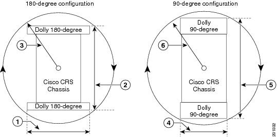
Some challenges moving a chassis on the dolly include limited hallway or doorway width, doorway thresholds, ramps, and tight corners along the transport route. To overcome these challenges, use the dolly in either of these configurations:
- 90-degree configuration— The dolly assemblies are shipped in this configuration. In some cases this configuration is needed to transport the chassis. Use the 90-degree configuration to move the chassis off of the pallet. Extra care should be used with this configuration to ensure that the chassis does not tip during transport.
- 180-degree configuration— This configuration is a more stable configuration for transporting the chassis. The 180-degree position is the recommended configuration for moving the chassis.
Both configurations are acceptable to transport the as-shipped chassis.
#con_105601/tab_79237 lists the specifications for the dolly.
|
Specification |
Value |
|---|---|
|
Weight (each component) |
126 lb (57.3 kg) |
|
Maximum recommended safe curb height |
1.5 in. (3.8 cm) |
Note |
In the event that the dolly supplied by Cisco is not the appropriate method of transportation, consult Cisco Technical Staff to determine a method of transportation appropriate for the site. Ensure that the alternate moving device is capable of moving the chassis safely, supporting the weight of the chassis, and is capable of preventing the chassis from tipping. |
Safety Guidelines
Caution |
Before you perform any procedure outlined in this document, review the safety guidelines in this section to avoid injuring yourself or damaging the equipment. |
These guidelines are for your safety and to protect equipment. Guidelines do not include all hazards. Be alert.
Note |
Review the safety warnings listed in Regulatory Compliance and Safety Information for the Cisco CRS Carrier Routing System before installing, configuring, or troubleshooting any installed card. |
- Never attempt to lift an object that might be too heavy for you to lift by yourself.
- Keep the work area clear and dust free during and after installation. Do not allow dirt or debris to enter into any laser-based components.
- Keep tools and router components away from walk areas.
- Do not wear loose clothing, jewelry, and other items that could get caught in the router while working with optical interface modules (OIMs), and their associated components.
- Use Cisco equipment in accordance with its specifications and product-usage instructions.
- Do not work alone if potentially hazardous conditions exist.
Verifying the Securing Location
Verifying the recommended space ensures that you have enough space available to perform the initial installation of the chassis and its components.
Before moving the chassis into position, make sure that you have properly prepared the site so that there is sufficient room for installation and maintenance.
For additional details on making your site ready for the chassis, see Cisco CRS Carrier Routing System 16-Slot Line Card Chassis Site Planning Guide and Cisco CRS Carrier Routing System Multishelf System Site Planning Guide .
Preventing Electrostatic Discharge
Electrostatic discharge (ESD) damage, which can occur when electronic cards or components are improperly handled, results in complete or intermittent failures. We recommend the use of an ESD-preventive strap whenever you handle network equipment or one of its components.
These guidelines for preventing ESD damage:
- Always use an ESD-preventive wrist or ankle strap, and ensure that it makes good skin contact. Connect the equipment end of the connection cord to an ESD connection socket on the router or to a bare metal surface on the chassis.
- Handle a card by its ejector levers, when applicable, or its metal carrier only; avoid touching the board or connector pins.
- Place a card removed from the chassis, component side up, on an antistatic surface or in a static-shielding bag. If you plan to return the component to the factory, immediately place it in a static-shielding bag.
- Avoid contact between the card and clothing. The wrist strap protects the board from only ESD voltage on the body: ESD voltage on clothing can still cause damage.
Caution |
When unpacking and setting parts aside, it is important to set them either in their original antistatic packaging or on an antistatic mat to avoid static discharge. |
Unpacking the Cisco Dolly
The dolly is a Cisco-supplied orderable item. The shipping crate contains the dolly units, positioned in the 90 degree configuration as shown in #task_80580/fig_80654. This section describes how to unpack and position the dollies.
Note |
The dolly will work with both the CRS 16-Slot Line Card Chassis (LCC) and the Fabric Card Chassis (FCC); the only difference is the lift brackets that are used (see #con_163725/fig_142684 and #con_163725/fig_142945). |
Note |
In the event that the dolly supplied by Cisco is not the appropriate method of transportation, consult Cisco Technical Staff to determine a method of transportation appropriate for the site. Ensure that the alternate moving device is capable of moving the chassis safely, supporting the weight of the chassis, and is capable of preventing the chassis from tipping. |
Prerequisites
No prerequisites exist for this task.
Required Tools and Equipment
You need the following tools (only used to remove packaging) to perform this task:
- 3/8-in. ratchet wrench
- 9/16-in. socket and a 5/8-in. socket
- Phillips #2 screwdriver (used to remove the clip from the dolly crate)
Caution |
The dolly should be used only for transporting the as-shipped chassis. |
Steps
To unpack the dolly, follow these steps:
SUMMARY STEPS
- Carefully move the pallet containing the dolly to the location where you plan to unpack it. The dolly arrives as two separate, identical units, one unit each for the front and back of the chassis.
- Remove the clip tool from the dolly shipping crate as shown in the following figure.
- Remove side panel from dolly crate. Swing open and lift off.
- Using the 3/8-in. ratchet wrench with 5/8-in. socket remove the two holding bolts from each side at the bottom of the dolly pallet base as shown in #task_80580/fig_80590.
- With at least two people, one on each side of the dolly shipping crate, tilt crate back and lift off pallet, then set the crate carefully aside as shown in #task_80580/fig_80624.
- Using the 3/8-in. ratchet wrench with 5/8-in. socket remove the two bolts and the dolly stopper as shown in the following figure.
- Release the caster brakes and remove the dolly from the pallet.
- Remove the LCC lift brackets from the dolly. Use the 3/8-in. ratchet wrench with 12-mm hex bit (provided by Cisco) to remove the two LCC dolly-to-chassis lift brackets and set the LCC lift brackets carefully aside. Repeat this step for the second dolly unit.
DETAILED STEPS
|
Step 1 |
Carefully move the pallet containing the dolly to the location where you plan to unpack it. The dolly arrives as two separate, identical units, one unit each for the front and back of the chassis. |
||||||||||||||||||||||||||||||||||||||||||||
|
Step 2 |
Remove the clip tool from the dolly shipping crate as shown in the following figure. 
|
||||||||||||||||||||||||||||||||||||||||||||
|
Step 3 |
Remove side panel from dolly crate. Swing open and lift off. |
||||||||||||||||||||||||||||||||||||||||||||
|
Step 4 |
Using the 3/8-in. ratchet wrench with 5/8-in. socket remove the two holding bolts from each side at the bottom of the dolly pallet base as shown in #task_80580/fig_80590. |
||||||||||||||||||||||||||||||||||||||||||||
|
Step 5 |
With at least two people, one on each side of the dolly shipping crate, tilt crate back and lift off pallet, then set the crate carefully aside as shown in #task_80580/fig_80624. 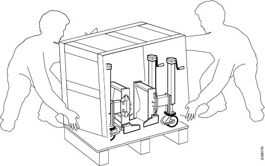 |
||||||||||||||||||||||||||||||||||||||||||||
|
Step 6 |
Using the 3/8-in. ratchet wrench with 5/8-in. socket remove the two bolts and the dolly stopper as shown in the following figure. 
|
||||||||||||||||||||||||||||||||||||||||||||
|
Step 7 |
Release the caster brakes and remove the dolly from the pallet. |
||||||||||||||||||||||||||||||||||||||||||||
|
Step 8 |
Remove the LCC lift brackets from the dolly. Use the 3/8-in. ratchet wrench with 12-mm hex bit (provided by Cisco) to remove the two LCC dolly-to-chassis lift brackets and set the LCC lift brackets carefully aside. Repeat this step for the second dolly unit.
#task_80580/fig_80654 shows the dolly 90-degree configuration with callouts pointing to components and LCC lift brackets (see #con_150081/fig_150102 for the dolly with FCC lift brackets) still attached. To use the dolly for a Cisco fabric card chassis, you must order the FCC lift brackets. 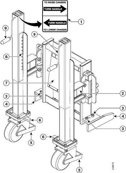
#task_80580/fig_80699 shows the dolly 180-degree configuration with callouts pointing to components and LCC lift brackets (#task_150146/fig_150182 for the dolly with FCC lift brackets) still attached. Both dolly units are identical. 
|
What to Do Next
After unpacking the dolly, unpack the chassis.
Unpacking the CRS Fabric Card Chassis
This section describes:
Required Tools and Equipment
You need:
- 3/8-in. ratchet wrench
- 10-mm hex bit (provided by Cisco included in the dolly packaging)
- 11/16-in. socket (to remove the top wood and frame cushion system)
- Ladder or step platform
Prepare the Fabric Card Chassis For Unpacking
The chassis is shipped on a pallet by itself in a plywood box. The chassis is unpacked before all other shipping boxes, except for the dolly lifting device.
Prerequisites
Before unpacking the chassis, be sure to have sufficient room around the chassis pallet for unpacking.
Steps
To prepare the chassis for unpacking, follow these steps:
SUMMARY STEPS
- Locate a large area to accommodate the chassis and move crate with pallet jack to that location.
- Go to the next section, c_Unpacking_the_Chassis_83177.xml#con_83177.
DETAILED STEPS
|
Step 1 |
Locate a large area to accommodate the chassis and move crate with pallet jack to that location.
|
||
|
Step 2 |
Go to the next section, c_Unpacking_the_Chassis_83177.xml#con_83177.
|
Unpacking the Chassis
Steps
To unpack the chassis, follow these steps:
SUMMARY STEPS
- Remove the hinge mechanisms from front door only. Raise and twist the lock hinges on the sides and the base of the plywood box .
- Remove the front cover and set it carefully aside.
- Disengage the remaining latches from the shipping box. There are two on each side of the shipping box.
- Using at least two people, lift and remove the three-sided box and place aside. The chassis is exposed on the pallet protected by a shipping bag secured with tape around the bag.
- The following figure shows the wooden box removed from the chassis and the protective bag still attached to the chassis with tape.
- You need a ladder to remove the four top cover bolts as shown in #task_83245/fig_163501. Use the 3/8-in. ratchet wrench with 11/16-in. socket to loosen the four bolts holding the top wood and frame cushion system from the top of the shipping box. Once the four bolts are loosened, remove each bolt manually and place aside, then remove the top wood and frame cushion system from the chassis.
- When you are ready to remove the chassis bag, unseal the tape that exists around the perimeter of the chassis (as shown in #task_83245/fig_128680) base and pull the bag off the chassis.
DETAILED STEPS
|
Step 1 |
Remove the hinge mechanisms from front door only. Raise and twist the lock hinges on the sides and the base of the plywood box . 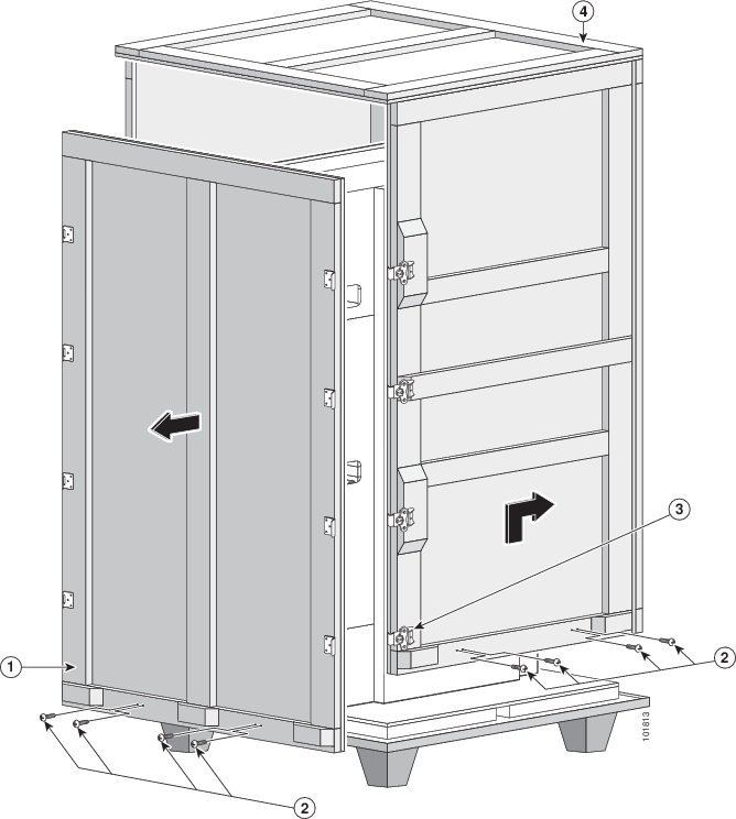
|
||||||||||||
|
Step 2 |
Remove the front cover and set it carefully aside.
|
||||||||||||
|
Step 3 |
Disengage the remaining latches from the shipping box. There are two on each side of the shipping box. |
||||||||||||
|
Step 4 |
Using at least two people, lift and remove the three-sided box and place aside. The chassis is exposed on the pallet protected by a shipping bag secured with tape around the bag. |
||||||||||||
|
Step 5 |
The following figure shows the wooden box removed from the chassis and the protective bag still attached to the chassis with tape. 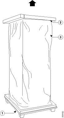
|
||||||||||||
|
Step 6 |
You need a ladder to remove the four top cover bolts as shown in #task_83245/fig_163501. Use the 3/8-in. ratchet wrench with 11/16-in. socket to loosen the four bolts holding the top wood and frame cushion system from the top of the shipping box. Once the four bolts are loosened, remove each bolt manually and place aside, then remove the top wood and frame cushion system from the chassis. 
|
||||||||||||
|
Step 7 |
When you are ready to remove the chassis bag, unseal the tape that exists around the perimeter of the chassis (as shown in #task_83245/fig_128680) base and pull the bag off the chassis. |
What to Do Next
After performing this task, go to the next section c_Attaching_the_Dolly_to_the_Chassis_and_Removing_the_Chassis_Pallet_163725.xml#con_163725.
Attaching the Dolly to the Chassis and Removing the Chassis Pallet
This section describes how to remove the LCC lift brackets from the dolly and use the FCC lift brackets, attach the dolly to the Cisco CRS FCC, and to remove the chassis shipping pallet. Only the 90-degree dolly configuration is used to remove the chassis from the pallet.
Note |
The dolly ships with the line card chassis (LCC) lift brackets installed, therefore you must order the FCC lift brackets (bolts are the same) for a Cisco fabric card chassis. See #con_163725/fig_142684 and #con_163725/fig_142945 for the differences in the lift brackets. |
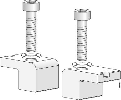
#con_163725/fig_142684 shows the LCC lift brackets and #con_163725/fig_142945 shows the FCC lift brackets and the bolts that both lift bracket types use.

|
1 |
From left to right—left front and right front lift brackets |
4 |
Two M14 x 50-mm socket-head cap screws s (used to bolt the front and rear lift brackets to the chassis) |
|
2 |
Side pins on each lift bracket (inserted into the chassis) |
5 |
Four M14 x 30-mm socket-head cap screws (used to bolt the front and rear lift brackets to the dolly) |
|
3 |
From left to right—Right rear and left rear lift brackets |
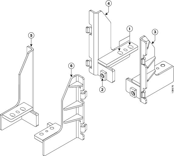
|
1 |
FCC holes for the four M14 x 30-mm socket-head cap screws (used to bolt the front and rear lift brackets to the dolly) See #con_163725/fig_142684. |
4 |
Right rear side lift bracket |
|
2 |
FCC holes for the two M14 x 40-mm socket-head cap screws s (used to bolt the front and rear lift brackets to the chassis) See#con_163725/fig_142945. |
5 |
Left front side lift bracket |
|
3 |
Left rear side lift bracket |
6 |
Right front side lift bracket |
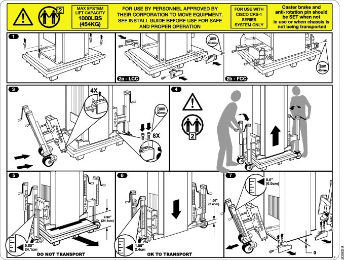
#con_163725/fig_86284 shows the dolly instruction label, which is part of the dolly and is located on the inside component of the dolly. Refer to this graphic when performing the steps to attach the dolly to the chassis.
Note |
The Instruction Label on the dolly shows illustrations for using the dolly with a line card chassis, except for label 2b-FCC (for fabric card chassis). The steps also apply to the fabric card chassis. If there are differences, these will be highlighted in the documentation. |
Prerequisites
Before attaching the dolly to the chassis, unpack the chassis and unpack the dolly, and remove LCC lift brackets from the dolly.
Required Tools and Equipment
You need these tools and part to perform this task:
- 2.5mm hex key (to remove the covers)
- 14-mm socket
- 3/8-in. ratchet wrench with 6-in. extension
- 12-mm hex bit (included in the dolly packaging)
- Dolly (Cisco product number CRS-16-LIFT/B)
- FCC lift brackets (CRS-FCC-LIFT-BRKT)
Steps
To attach the dolly to the fabric card chassis, follow these steps:
SUMMARY STEPS
- Using the Hex socket and wrench remove the four bolts (½-13 x 3.5 in. long hex-head) that connect the pallet to each corner of the chassis base as shown in #task_87167/fig_88737.
- Select a FCC lift bracket (the LCC lift brackets have already been removed), as shown in #con_163725/fig_142945. There are two identical lift brackets for the right front and left rear and two identical lift brackets for the right rear and left front.
- Fit the FCC brackets on all four sides of the chassis.
- Bolt the FCC lift brackets to the chassis. Insert the 40-mm socket-head cap screw that connects the left lift bracket to the bolt block on the lower front corner of the front side of the chassis, and use the 14-mm hex drive socket to tighten it. Repeat this step for the right lift bracket to attach the bracket to the chassis. See #task_87167/fig_134014.
- Repeat #task_87167/_181917 and #task_87167/_181883 for the rear side of the chassis.
- If the dolly caster brakes are locked, then release them and slide the dolly towards the lift brackets on the chassis as shown in #task_87167/fig_180547 so that the pins on the upper side of the unit align with the holes on the lift brackets on the PLIM side of the chassis. The dolly and lift brackets must align with each other to easily insert the bolts and secure the dolly to the lift brackets.
- Bolt the lift brackets to the dolly. Insert the 30-mm socket-head cap screws (shorter screw, as shown in #con_163725/fig_142684) and use the 14-mm hex drive socket to tighten it. Repeat this step for the right lift bracket to insert the two bolts that bolt the lift bracket to the dolly.
- Repeat #task_87167/_178529 and #task_87167/_178534 for the rear (MSC) side of the chassis.
- After all bolts are secured, remove the chassis pallet following these steps:
DETAILED STEPS
|
Step 1 |
Using the Hex socket and wrench remove the four bolts (½-13 x 3.5 in. long hex-head) that connect the pallet to each corner of the chassis base as shown in #task_87167/fig_88737. 
|
||
|
Step 2 |
Select a FCC lift bracket (the LCC lift brackets have already been removed), as shown in #con_163725/fig_142945. There are two identical lift brackets for the right front and left rear and two identical lift brackets for the right rear and left front. |
||
|
Step 3 |
Fit the FCC brackets on all four sides of the chassis.
|
||
|
Step 4 |
Bolt the FCC lift brackets to the chassis. Insert the 40-mm socket-head cap screw that connects the left lift bracket to the bolt block on the lower front corner of the front side of the chassis, and use the 14-mm hex drive socket to tighten it. Repeat this step for the right lift bracket to attach the bracket to the chassis. See #task_87167/fig_134014. 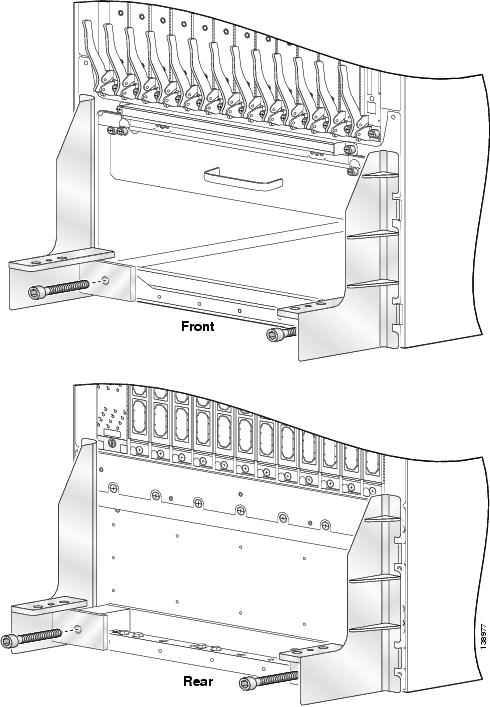 |
||
|
Step 5 |
Repeat #task_87167/_181917 and #task_87167/_181883 for the rear side of the chassis. |
||
|
Step 6 |
If the dolly caster brakes are locked, then release them and slide the dolly towards the lift brackets on the chassis as shown in #task_87167/fig_180547 so that the pins on the upper side of the unit align with the holes on the lift brackets on the PLIM side of the chassis. The dolly and lift brackets must align with each other to easily insert the bolts and secure the dolly to the lift brackets. 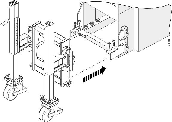 |
||
|
Step 7 |
Bolt the lift brackets to the dolly. Insert the 30-mm socket-head cap screws (shorter screw, as shown in #con_163725/fig_142684) and use the 14-mm hex drive socket to tighten it. Repeat this step for the right lift bracket to insert the two bolts that bolt the lift bracket to the dolly. |
||
|
Step 8 |
Repeat #task_87167/_178529 and #task_87167/_178534 for the rear (MSC) side of the chassis. |
||
|
Step 9 |
After all bolts are secured, remove the chassis pallet following these steps:
|


What to Do Next
After removing the shipping pallet from the chassis, move the chassis. First read the c_Important_Notice_About_Transporting_the_Chassis_160345.xml#con_160345.
Important Notice About Transporting the Chassis
Either a fork lift or pallet jack can be used to transport a crated chassis only.
Throughout this document we refer to the dolly (supplied by Cisco) as the required means to transport the uncrated chassis from the shipping dock to the chassis final location.
Note |
In the event that the dolly supplied by Cisco is not the appropriate method of transportation, consult Cisco Technical Staff to determine a method of transportation appropriate for the site. Ensure that the alternate moving device is capable of moving the chassis safely, supporting the weight of the chassis, and is capable of preventing the chassis from tipping. |
Caution |
When using any type of device to transport the chassis, exercise extreme caution and follow proper safety practices. |
Moving the CRS Fabric Card Chassis
This section presents these topics:
Cisco Dolly and Chassis Moving Guidelines
When you use the dolly to move the FCC, follow these guidelines:
- When using the dolly to move the chassis, you should make sure that the chassis is empty of components, as shipped.
-
When raising or lowering the chassis
, follow these guidelines:
- Make sure that you have at least one person on each side of the chassis to turn the lifting cranks on the dolly as simultaneously as possible.
- Raise or lower the chassis only on a level surface.
- Make sure that the caster brakes and antirotation pins are in the locked position.
- Keep the casters on the floor at all times when you are raising or lowering the chassis.
- Attempt to keep the chassis itself as level as possible when raising or lowering it with the dolly.
- Use the height label on the dolly to make sure that you have the correct amount of ground clearance. (The label shows the recommended transport chassis engagement height, the height that is not to be exceeded, and to ensure correct alignment between both dolly wheel assemblies.)
-
When moving the chassis using a dolly
, follow these guidelines:
- Make sure that you have at least two people to transport the chassis. Never transport the chassis by yourself.
- Use the dolly in the 180-degree configuration whenever possible when you move the chassis. This configuration requires you to have passageways at least 50 inches in width to accommodate the combined dolly and chassis width.
- Use the dolly in the 90-degree configuration if your site restrictions require it. If hallway constraints require you to use the 90-degree dolly configuration (24 inches), the chassis is more likely to tip, so use extra care when transporting the chassis in that configuration.
- Dolly is used to transport the chassis. To reduce the risk of dolly instability, chassis damage, or personal injury, do not raise the equipment more than 1 inch (2.54 cm) above the floor during transportation.
- Dolly can be used to transport the chassis over thresholds up to 1.5 inches.
-
When transporting the chassis on a ramp
, follow these guidelines:
- Make sure that you have at least two people to transport the chassis up and down a ramp. One person in the rear pushing, one person at the front pulling, and one steering the chassis.
- Dolly is optimized to move the chassis on flat surfaces. It is not designed to move the chassis on ramps greater than 1 inch of rise for every 6 inches of run. If the ramp exceeds this maximum limit, consult with Cisco Technical Staff.
- Exercise extreme caution when moving chassis up an incline of any angle.
Caution |
Use the recommended 180-degree configuration to transport a chassis. If the 90-degree configuration is used, then the chassis is more likely to tip. Use caution and take extra care in rolling the chassis up a ramp. Always follow proper safety practices whenever moving a CRS chassis. |
Note |
The following warning statements are also documented in the Cisco Regulatory Compliance and Safety Information for the Cisco CRS Carrier Routing System . |
DANGER |
Cisco does NOT recommend moving a fully populated chassis. |
DANGER |
This dolly is designed only for the temporary transportation of the Cisco equipment listed here. Do not use it with any other device or for any other purpose. Cisco equipment designed for use with the dolly: Cisco CRS fabric card chassis and line card chassis (CRS-FCC, CRS-16-LCC). Statement 356 |
DANGER |
Do not permanently locate the equipment on the dolly. Safely store the dolly after use. Statement 357 |
DANGER |
To reduce the risk of dolly instability, chassis damage, or personal injury, do not raise the equipment more than 1 inch (2.54 cm) above the floor during transportation. Statement 358 |
DANGER |
This dolly is designed to transport the equipment over short distances only. Statement 359 |
DANGER |
In order to reduce the risk of chassis damage or personal injury when replacing a fully-loaded, existing FCC chassis, do not move the chassis in a configuration that is greater than the as-shipped chassis. Before attaching the dolly and moving the chassis, remove power modules, switch fabric and fiber modules from the chassis. Statement 367 |
DANGER |
To reduce the risk of dolly instability, chassis damage, or personal injury, do not transport the equipment with the dolly raised higher than the maximum transport height shown on the dolly label, and do not raise the equipment higher than required to remove the shipping pallet. For information about maximum dolly heights, see the dolly instructions in this document. Statement 368 |
Caution |
Dolly wheel casters and anti-rotation pins should be in the locked position when the dolly is not in use. |
Verifying the Move Path
Before moving the chassis, it is critical that you verify that the path that you are planning to use, to move the chassis to its final location, can accommodate the chassis size and weight and the restrictions of the chassis when using the dolly (see the c_Dolly_Specifications_105601.xml#con_105601).
See #con_50080/tab_57943 for a list of the restrictions for your move path, and verify that you have sufficient room for the entire move path prior to moving the chassis.
|
Height (on dolly, with recommended 1 in. raise) |
81 in. (205 cm) |
|
Depth (on dolly, 90-degree dolly position) |
70 in. (178 cm) |
|
Depth (on dolly, 180-degree dolly position) |
48 in. (122 cm) |
|
Width (on dolly, 90-degree dolly position) |
23.6 in. (60 cm) |
|
Width (on dolly, 180-degree dolly position) |
44 in. (112 cm) |
|
Turning radius (on dolly, 90-degree dolly position) |
37 in. (94 cm) |
|
Turning radius (on dolly, 180-degree dolly position) |
33 in. (83 cm) |
|
Weight of chassis (as shipped, packaging removed) |
1175 lb (533 kg), Estimated |
|
Weight of dolly (both units) |
252 lb (114.5 kg) |
|
Maximum recommended height above floor (for chassis on dolly) |
1.5 in. (3.8 cm) |
Note |
Allow a gap of between 4 in. to 6 in. (10 cm to 15 cm) on each side of the chassis when moving it. |
#con_50080/fig_100216 shows the recommended minimum space to turn the chassis on the dolly in its 90-degree and 180-degree configuration.
|
1 |
Width (on dolly, 180-degree position) 44 in. (112 cm) |
4 |
Width (on dolly, 90-degree position) 24 in. (60 cm) |
|
2 |
Depth (on dolly, 180-degree position) 48 in. (122 cm) |
5 |
Depth (on dolly, 90-degree position) 70 in. (178 cm) |
|
3 |
Turn radius (on dolly, 180-degree position) 33 in. (83 cm) |
6 |
Turn radius (on dolly, 90-degree position) 37 in. (94cm) |
#con_50080/tab_100254 provides the dolly width and the recommended aisle width turning radius for the 90-degree and 180-degree dolly configuration.
|
Dolly Configuration |
Width of Dolly |
Recommended Aisle Width |
|---|---|---|
|
90-degree dolly position |
24 in. (60 cm) |
32 in. (81 cm)* |
|
180-degree dolly position |
44 in. (112 cm) |
52 in. (132 cm) |
|
*Aisle width may need to be more than 32 inches when transporting the chassis around a corner. |
#con_50080/fig_125014 is a top view of the minimum aisle space required to install the Cisco CRS fabric card chassis without using the dolly supplied by Cisco.

|
1 |
Chassis front |
4 |
Chassis rear |
|
2 |
Chassis side |
5 |
Chassis side |
|
3 |
Moving space requirement 37.4 in (95 cm) |
Moving the Chassis
Prerequisites
Before performing this task, make sure that the dolly is in the correct configuration, is firmly attached to the chassis, and that the dolly brakes are in the locked position.
Note |
If a dolly configuration change is required, the go to the section, c_Modifying_the_Dolly_Configuration_to_Move_the_Chassis_150081.xml#con_150081. |
Steps
This section describes how to move the FCC:
SUMMARY STEPS
- With a person on each side of the chassis, turn all four lifting cranks of the dolly slowly clockwise. Lift the dolly to the Transport marking on the height label on each lift assembly leg. The dolly must be used to transport the chassis unless an alternate moving method has been approved by Cisco. To reduce the risk of dolly instability, chassis damage, or personal injury, do not raise the equipment more than 1 in. (2.54 cm) above the floor during transportation which is the standard recommendation for flat surfaces and thresholds.
- Unlock the dolly caster antirotation and brake systems.
- Use at least two people to transport the chassis up any ramp. Position one person in the front of the chassis to pull, one person at the rear of chassis to push, and one person steering the chassis to transport the chassis.
- Roll the chassis carefully into position. #task_97906/fig_170084 shows a typical floor plan from the top of the chassis. For additional details on making your site ready for the chassis, see Cisco CRS Carrier Routing System Multishelf System Site Planning Guide .
- Remove the dolly.
DETAILED STEPS
|
Step 1 |
With a person on each side of the chassis, turn all four lifting cranks of the dolly slowly clockwise. Lift the dolly to the Transport marking on the height label on each lift assembly leg. The dolly must be used to transport the chassis unless an alternate moving method has been approved by Cisco. To reduce the risk of dolly instability, chassis damage, or personal injury, do not raise the equipment more than 1 in. (2.54 cm) above the floor during transportation which is the standard recommendation for flat surfaces and thresholds.
|
||||||||
|
Step 2 |
Unlock the dolly caster antirotation and brake systems.
|
||||||||
|
Step 3 |
Use at least two people to transport the chassis up any ramp. Position one person in the front of the chassis to pull, one person at the rear of chassis to push, and one person steering the chassis to transport the chassis. |
||||||||
|
Step 4 |
Roll the chassis carefully into position. #task_97906/fig_170084 shows a typical floor plan from the top of the chassis. For additional details on making your site ready for the chassis, see Cisco CRS Carrier Routing System Multishelf System Site Planning Guide . #task_97906/fig_170084 shows a typical site floor plan for a Cisco FCC.  |
||||||||
|
Step 5 |
Remove the dolly. |
What to Do Next
After moving the chassis, secure the chassis.
DANGER |
Do not permanently locate the equipment on the dolly. Safely store the dolly after use. Statement 357 |
Securing the Chassis
This section presents these topics:
Site Preparation
Before moving the chassis into place and securing it, you must make sure that your site is prepared. Because of its size and weight issues, the chassis must be securely bolted to the floor. Several possible bolting configurations exist for the chassis, including using the optional alternate chassis floor-mounting kit. Bolt hole templates are provided for the various securing options.
For complete details on preparing your site for the chassis, see Cisco CRS Carrier Routing System Fabric Card Chassis Site Planning Guide .
Bolt Hole Templates
Cisco provides two bolt hole layout templates to help you determine where to install the system:
- An aluminum plate template (CRS-LCC-DRILLTEMP(=)) shows the chassis footprint and the pattern of holes that must be drilled into the floor for the mounting brackets that secure the chassis to the floor.
- A mylar template (CRS-LCC-FLOORTEMP(=)) shows the chassis footprint, door swings, and required clearances to remove and replace chassis components. You can use this template to plan the aisle space required for the installation and maintenance of a line card chassis.
Complete information about the templates and floor plans, clearance information, and planning for future space needs, is included in Cisco CRS Carrier Routing System Fabric Card Chassis Site Planning Guide .
Securing the Chassis To the Floor
This section describes how to secure the Cisco CRS FCC to a concrete floor. The chassis is shipped with a drill hole template (CRS-LCC-DRILLTEMP(=)) to assist you in putting the bolts in the proper position on the floor. The template is used for both raised floors and slabs. The drill hole template identifies primary, secondary and alternate mounting locations for securing the chassis to the floor. Whenever possible, use the:
- Primary mounting locations
- Second and alternate locations only when the primary locations are not available
If alternate mounting locations are used, an alternate chassis mounting kit (CRS-FCC-ALTMNT) (orderable from Cisco) needs to be installed on the chassis
The instructions in this section are specific to securing the chassis to a concrete floor. The instructions for securing the chassis to a raised floor vary from site to site, depending on such details as whether your floor needs additional support (as local practice applies for raised floors), where (depending on the location of the floor tiles) the bolt holes need to be and so on. Work with your facilities representative to determine your needs for your particular site.
Prerequisites
Identify chassis location before performing this task.
Required Tools and Equipment
You need the following parts to perform this task:
- 3/8-in. ratchet wrench
- Set of standard and metric sockets
- Drill and bits for masonry and wood
Note |
The full list of tools depends on the anchor bolt kit you use. See the documentation for your anchor bolt kit for details. |
Steps
SUMMARY STEPS
- Using the drill hole template, drill pilot holes into the floor at the identified locations.
- Refer to your mounting kit instructions for anchoring hardware to the floor. Remove the drill hole template, and drill the indicated anchor bolt holes into the floor at the pilot hole locations.
- Carefully move the chassis into place over the bolt holes. See the c_Moving_the_Chassis_169192.xml#con_169192 for details on moving the chassis with the dolly.
- Lock the dolly caster antirotation and brake systems.
- With a person on each side of the chassis, turn all four lifting cranks of the dolly counterclockwise slowly to lower the chassis to the floor.
- Remove the dolly from the chassis.
- Insert all anchor bolts.
- Tighten all bolts and nuts.
- Replace corner brackets on the chassis.
DETAILED STEPS
|
Step 1 |
Using the drill hole template, drill pilot holes into the floor at the identified locations. |
||
|
Step 2 |
Refer to your mounting kit instructions for anchoring hardware to the floor. Remove the drill hole template, and drill the indicated anchor bolt holes into the floor at the pilot hole locations. |
||
|
Step 3 |
Carefully move the chassis into place over the bolt holes. See the c_Moving_the_Chassis_169192.xml#con_169192 for details on moving the chassis with the dolly.
|
||
|
Step 4 |
Lock the dolly caster antirotation and brake systems. |
||
|
Step 5 |
With a person on each side of the chassis, turn all four lifting cranks of the dolly counterclockwise slowly to lower the chassis to the floor.
|
||
|
Step 6 |
Remove the dolly from the chassis. |
||
|
Step 7 |
Insert all anchor bolts. |
||
|
Step 8 |
Tighten all bolts and nuts. |
||
|
Step 9 |
Replace corner brackets on the chassis. |
Modifying the Dolly Configuration to Move the Chassis
This section describes how to modify the dolly from one configuration to another if your site requires it. The dolly can be configured in either the 180-degree or 90-degree position, depending on the needs of your site. For further information on the two configurations, see the c_Dolly_Specifications_105601.xml#con_105601. See the c_Cisco_Dolly_and_Chassis_Moving_Guidelines_39507.xml#con_39507 section for important recommendations before modifying the dolly configuration.
When changing the configuration of the dolly wheel assemblies (from 180 to 90 degrees or conversely) , follow these guidelines:
- Lower the chassis to the floor before you change configurations.
- Unlock the brake or antirotation on the casters only when you are ready to actually change the configuration (move the lift swing arm bracket). When you are preparing to change the configuration (remove bolts), make sure that the brakes and antirotation pin are in the locked position.
- Change the dolly configuration one caster at a time. Take your time and do not rush through the process.
- Make sure that the bolts are secured after you have completed changing the configuration.
#con_150081/fig_150102 shows the dolly with FCC lift brackets and its components in the 90-degree position.

|
1 |
Dolly handle label |
6 |
Caster antirotation pins |
|
2 |
Swing component for dolly (used to change the dolly configuration) |
7 |
Label showing how to attach dolly to chassis |
|
3 |
Lift bracket bolts |
8 |
Move height calibration label |
|
4 |
Lift brackets |
9 |
Lifting cranks |
|
5 |
Brakes |
Prerequisites
Before performing this task, make certain that the chassis and pallet are on the floor.
Required Tools and Equipment
You need a 3/8-in. ratchet wrench with 12-mm hex bit (provided by Cisco) to perform this task.
Steps
To change the dolly configuration from the 90-degree configuration to the 180-degree transport configuration, follow these steps:
SUMMARY STEPS
- Set the caster wheel rotation using the caster antirotation pin. Turn the antirotation pin to a vertical position to lock the caster. See #con_150081/fig_150102.
- Lock the brakes. Depress the brakes (#con_150081/fig_150102) on each side of the dolly.
- Using the handles, turn the dolly lifting cranks to raise or lower the dolly according to the label rotation direction (see #task_87167/fig_164936). Turn the lifting cranks until the dolly casters are just off the floor.
- Unlock the dolly caster brakes and antirotation pins.
- On the dolly unit attached to the front fabric card side of the chassis, use the wrench to remove the two holding bolts on the left side lift arm swing bracket.
- Swing the lift arm swing bracket to the side as shown in #task_150146/fig_150171. Reinsert the holding bolts and partially tighten the bolts.
- On the dolly unit attached to the front side of the fabric card chassis, use the 3/8-in. ratchet wrench with 12-mm hex bit (provided by Cisco) to remove the two holding bolts on the left side lift arm swing bracket to convert to the 180-degree configuration.
- Repeat steps 5, 6 and 7 for the right side lift arm swing bracket. #task_150146/fig_150182 shows the dolly in the 180-degree position with FCC lift brackets.
- Lock the dolly caster brakes and antirotation pins until you are ready to move the chassis.
- Repeat steps 1 through 8 for the other dolly component.
- Using the wrench, firmly tighten the holding bolts.
DETAILED STEPS
|
Step 1 |
Set the caster wheel rotation using the caster antirotation pin. Turn the antirotation pin to a vertical position to lock the caster. See #con_150081/fig_150102. |
||||||||||||||||||||
|
Step 2 |
Lock the brakes. Depress the brakes (#con_150081/fig_150102) on each side of the dolly. |
||||||||||||||||||||
|
Step 3 |
Using the handles, turn the dolly lifting cranks to raise or lower the dolly according to the label rotation direction (see #task_87167/fig_164936). Turn the lifting cranks until the dolly casters are just off the floor. |
||||||||||||||||||||
|
Step 4 |
Unlock the dolly caster brakes and antirotation pins. |
||||||||||||||||||||
|
Step 5 |
On the dolly unit attached to the front fabric card side of the chassis, use the wrench to remove the two holding bolts on the left side lift arm swing bracket. |
||||||||||||||||||||
|
Step 6 |
Swing the lift arm swing bracket to the side as shown in #task_150146/fig_150171. Reinsert the holding bolts and partially tighten the bolts. |
||||||||||||||||||||
|
Step 7 |
On the dolly unit attached to the front side of the fabric card chassis, use the 3/8-in. ratchet wrench with 12-mm hex bit (provided by Cisco) to remove the two holding bolts on the left side lift arm swing bracket to convert to the 180-degree configuration. 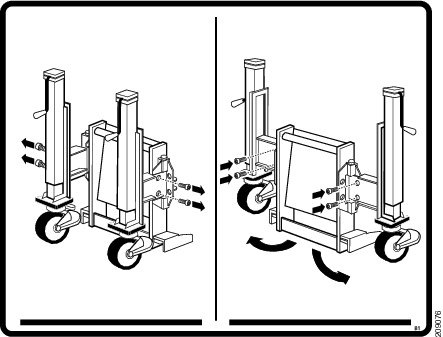 |
||||||||||||||||||||
|
Step 8 |
Repeat steps 5, 6 and 7 for the right side lift arm swing bracket. #task_150146/fig_150182 shows the dolly in the 180-degree position with FCC lift brackets. 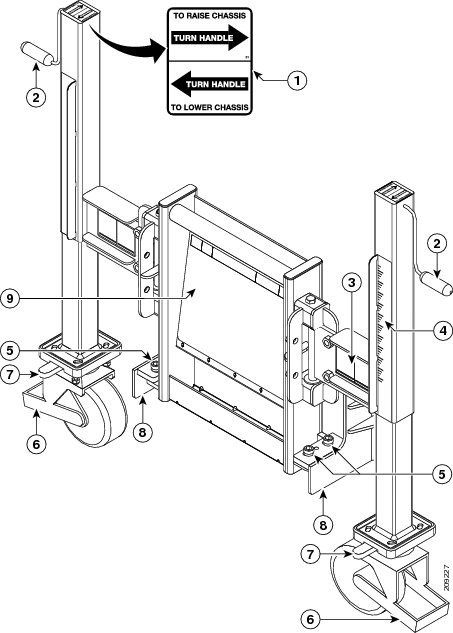
|
||||||||||||||||||||
|
Step 9 |
Lock the dolly caster brakes and antirotation pins until you are ready to move the chassis. |
||||||||||||||||||||
|
Step 10 |
Repeat steps 1 through 8 for the other dolly component. |
||||||||||||||||||||
|
Step 11 |
Using the wrench, firmly tighten the holding bolts.
|
Installing the Alternate Chassis Floor-Mounting Kit
This section describes how to attach the alternate chassis floor mount kit (see #con_74083/fig_74094) to the FCC. The kit allows you to mount the chassis to the floor by providing offset holes for mounting. Primary and secondary bolt locations exist for securing the chassis to the floor. The drill template that is shipped with the chassis has two locations available for bolting the chassis the floor; the alternate chassis floor mount kit is needed if your site is such that you cannot bolt the chassis down at the primary or secondary location. See Cisco CRS Carrier Routing System Multishelf System Site Planning Guide for further details.
Note |
The alternate chassis floor mount kit is an orderable item. If you cannot use the primary or secondary mounting holes, then use the optional alternate chassis floor mount kit for an alternate set of mounting holes. Use this kit only if there is no other means to mount the chassis to the floor. |
Note |
The front fabric cards and rear (OIM) side alternate chassis floor mount kit blocks are both installed from the front fabric card side of chassis. |
Prerequisites
Before installing the alternate chassis floor mount kit, you must prepare the floor, unpack the chassis, move the chassis into position, and remove the lower fan tray. To remove a fan tray, see the Cisco CRS Carrier Routing System Fabric Card Chassis Installation Guide .
Required Tools and Equipment
You need these tools and part to perform this task:
- Drill hole template (Cisco product number CRS-LCC-DRILLTEMP(=)
- 12-mm Hex wrench
- Alternate chassis floor-mounting kit (Cisco product number CRS-FCC-ALTMNT(=)
Steps
To install an alternate chassis floor-mounting kit, follow these steps:
SUMMARY STEPS
- Make sure that the lower fan tray has been removed.
- Install the front fabric card side alternate chassis floor-mounting kit blocks (one for each side) as outlined in steps 3 and 4.
- Insert the two alternate chassis floor-mounting bolt blocks (one for each side) into the front fabric card side of the chassis (see #task_74115/fig_74125).
- Insert the two 12-mm hex bolts (one for each bolt block) into the holes on the top of the alternate chassis floor-mounting bolt blocks, and use the 12-mm hex wrench to fully tighten the bolts to secure the bolt blocks to the chassis and the chassis to the floor.
- Install the rear (OIM) side alternate chassis floor-mounting blocks (one for each side) as outlined in steps 6 and 7.
- Insert the two alternate chassis floor-mounting bolt blocks (one for each side) into the rear (OIM) side of the interior of the chassis (see #task_74115/fig_74139).
- Insert the two 12-mm hex bolts (one for each bolt block) into the holes on the top of the alternate chassis floor-mounting bolt blocks, and use the 12-mm hex wrench to fully tighten the bolts to secure the bolt blocks to the chassis and the chassis to the floor.
DETAILED STEPS
|
Step 1 |
Make sure that the lower fan tray has been removed. |
||
|
Step 2 |
Install the front fabric card side alternate chassis floor-mounting kit blocks (one for each side) as outlined in steps 3 and 4. |
||
|
Step 3 |
Insert the two alternate chassis floor-mounting bolt blocks (one for each side) into the front fabric card side of the chassis (see #task_74115/fig_74125).  |
||
|
Step 4 |
Insert the two 12-mm hex bolts (one for each bolt block) into the holes on the top of the alternate chassis floor-mounting bolt blocks, and use the 12-mm hex wrench to fully tighten the bolts to secure the bolt blocks to the chassis and the chassis to the floor.
|
||
|
Step 5 |
Install the rear (OIM) side alternate chassis floor-mounting blocks (one for each side) as outlined in steps 6 and 7.
|
||
|
Step 6 |
Insert the two alternate chassis floor-mounting bolt blocks (one for each side) into the rear (OIM) side of the interior of the chassis (see #task_74115/fig_74139). 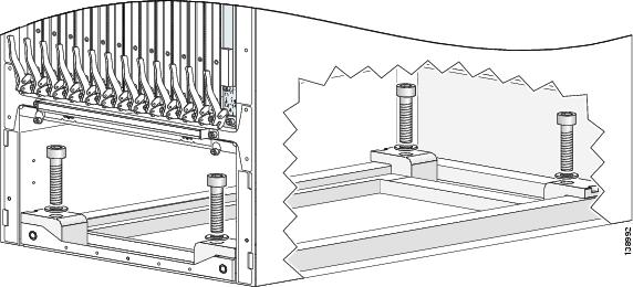 |
||
|
Step 7 |
Insert the two 12-mm hex bolts (one for each bolt block) into the holes on the top of the alternate chassis floor-mounting bolt blocks, and use the 12-mm hex wrench to fully tighten the bolts to secure the bolt blocks to the chassis and the chassis to the floor. |
What to Do Next
After installing the alternate chassis floor-mounting kit and securing the chassis to the floor, you need to unpack and install all remaining chassis parts. See the c_Unpacking_the_Other_Pallets_90367.xml#con_90367 for unpacking information and Cisco CRS Carrier Routing System Fabric Card Chassis Installation Guide to locate the installation instructions for the individual parts.
Unpacking the Other Pallets
This section describes how to unpack the primary, secondary, power, and exterior cosmetic component pallets for the FCC.
Prerequisites
No prerequisites exist for this task.
Required Tools and Equipment
You need these tools to perform this task:
- Antistatic mat
- Phillips #2 screwdriver
- A pair of scissors
Steps
To unpack the pallets, follow these steps:
SUMMARY STEPS
- If possible, move the pallets to the same location as the unpacked and secured chassis. If that is not possible, move the individual boxes containing the various components to the chassis location.
- Use the pair of scissors to cut the straps that hold the packages to the pallet.
- Unpack all primary pallet parts from the packaging, and set the parts carefully aside on the antistatic mat for installation.
- Unpack all secondary pallet parts from the packaging, and set the parts carefully aside on the antistatic mat for installation.
- Unpack all power components from the packaging, and set the components carefully aside.
- Unpack exterior cosmetic components from the packaging, and set the components carefully aside on an ESD-immune surface for installation.
DETAILED STEPS
|
Step 1 |
If possible, move the pallets to the same location as the unpacked and secured chassis. If that is not possible, move the individual boxes containing the various components to the chassis location.
|
||||
|
Step 2 |
Use the pair of scissors to cut the straps that hold the packages to the pallet. |
||||
|
Step 3 |
Unpack all primary pallet parts from the packaging, and set the parts carefully aside on the antistatic mat for installation.
|
||||
|
Step 4 |
Unpack all secondary pallet parts from the packaging, and set the parts carefully aside on the antistatic mat for installation.
|
||||
|
Step 5 |
Unpack all power components from the packaging, and set the components carefully aside. |
||||
|
Step 6 |
Unpack exterior cosmetic components from the packaging, and set the components carefully aside on an ESD-immune surface for installation.
|
Component Return Information
Before preparing to ship back the product or product components, you must contact Cisco technical support and provide them with the details of your difficulty. Technical support needs to confirm your product or component failure prior to assigning a RMA number for return shipment. For additional information, see the c_Obtaining_Documentation_and_Submitting_a_Service_Request_158209.xml#con_158209.
To facilitate your conversation with technical support, locate and note the serial number for the chassis. The serial number label for the FCC is located on the rear (OIM) side of the FCC (see #con_39520/fig_67707).

Printed in the USA on recycled paper containing 10% postconsumer waste.
 Feedback