Chassis Overview
This chapter provides an overview of the Cisco CRS Carrier Routing System 8-Slot Line Card Chassis Enhanced router and the basic system configuration. It contains the following topics:
Overview
The Cisco CRS 8-slot Line Card Chassis Enhanced router supports 40 G, 140 G, and 400 G fabric cards and line cards. The Cisco CRS 8-Slot Line Card Chassis Enhanced router consists of one of the following:
- A single, 8-slot, 40-Gbps-per-slot line-card shelf for a total switching capacity of 640 Gbps
- A single, 8-slot, 140-Gbps-per-slot line-card shelf for a total switching capacity of 2.24 Tbps
- A single, 8-slot, 400-Gbps-per-slot line-card shelf for a total switching capacity of 12.8 Tbps
The 8-slot chassis is a half-height, rack-mounted 8-slot version of the Cisco CRS 16-Slot Line Card Chassis Enhanced router.
The routing systems are built around a scalable, distributed three-stage switch fabric and a variety of line card (packet) interfaces. These packet interfaces are located on modular services cards (MSCs), forwarding processors (FP), or label switch processor (LSP) cards and their associated physical layer interface modules (PLIMs) which can be referred to as line cards and are effectively cross-connected to each other through the switch fabric. MSC, FP, and LSP cards are also referred to as line cards.
The routing system consists of a single, rack-mounted Cisco CRS 8-Slot Line Card Chassis Enhanced router that contains the system components:
- Up to eight MSC, FP, or LSP line cards.
- Up to eight physical layer interface modules or PLIMs (one for each line card).
- Route processor (RP) cards (up to two) or performance route processor (PRP) cards (up to two)
- Switch fabric cards (four required)
- SPA Interface
Processors (SIPs) and Shared Port Adapters (SPAs) which can be installed
instead of PLIMs.
- SIP is a carrier card that is similar to a PLIM and inserts into a Cisco CRS Line Card Chassis Enhanced router slot and interconnects to a line card like a PLIM does. Unlike PLIMs, SIPs provide no network connectivity on their own.
- SPA is a modular type of port adapter that inserts into a subslot of a compatible SIP carrier card to provide network connectivity and increased interface port density. A SIP can hold one or more SPAs, depending on the SIP type and the SPA size. POS/SDH and Gigabit Ethernet SPAs are available.
- A chassis midplane that connects MSCs, FPs, and LSPs to their PLIMs and to switch fabric cards
The Cisco CRS 8-slot Line Card Chassis Enhanced router supports 40G, 140G, and 400G fabric cards, as follows:
- The Cisco CRS-1 Carrier Routing System uses fabric cards designed for 40 G operation (CRS-8-FC/S or CRS-8-FC/M cards).
- The Cisco CRS-3 Carrier Routing System uses fabric cards designed for 140G operation (CRS-8-FC140/S or CRS-8-FC140/M cards).
- The Cisco CRS-X Carrier Routing System uses fabric cards designed for 400G operation (CRS-8-FC400/S fabric card or CRS-8-FC400/M fabric card). For detailed information about the CRS back-to-back system, see Introduction to the CRS-3 Back-to-Back System.
A mixture of 40G, 140G, and 400G fabric cards is not supported except during migration.
 Note |
Throughout this document, the generic term Cisco CRS Carrier Routing system refers to the Cisco CRS-1, Cisco CRS-3, and Cisco CRS-X Carrier Routing Systems, unless otherwise specified. |
Cisco 8-Slot Chassis Components
This section lists the main components of a Cisco CRS 8-slot line card chassis. It primarily identifies the components that are considered field-replaceable units (FRUs), but where additional detail is useful identifies subassemblies that are not field replaceable. This section contains these topics:
Power Components
The Cisco CRS 8-slot Line Card Chassis Enhanced router contains a power system that provides redundant power to the chassis.
The Cisco CRS 8-slot Line Card Chassis Enhanced router uses either AC or DC power.
The Cisco CRS 8-slot Line Card Chassis Enhanced router contains two power shelves with either up to three AC PMs per power shelf or up to four DC power modules (PMs).
#con_1105774/fig_1106501 shows the front view of two Cisco CRS 8-slot Line Card Chassis Enhanced routers - one with an AC modular configuration power supply installed and one with a DC modular configuration power supply installed.

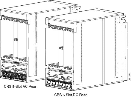
#con_1105774/fig_1106511 shows the rear view of two Cisco CRS 8-slot Line Card Chassis Enhanced routers - one with an AC modular configuration power supply installed and one with a DC modular configuration power supply installed.
Routing and Switch Fabric Components
The Cisco CRS 8-slot Line Card Chassis Enhanced router contains:
- As many as eight MSC, FP, and LSP cards (all types are also called line cards), and eight PLIMs. The line card and PLIM are an associated pair of cards that mate through the chassis midplane. The line card provides the forwarding engine for Layer 3 routing of user data, and the PLIM provides the physical interface and connectors for the user data. The line card can be associated with several different PLIMs, which provide different interface speeds and technologies.
Note |
For a complete list of line cards, route processors, SPAs and SIPs, and interface modules supported in the Cisco CRS 8-slot line card chassis, go to the Cisco Carrier Routing System Data Sheets at: http://www.cisco.com/en/US/products/ps5763/products_data_sheets_list.html |
- A chassis midplane that connects line cards to their associated PLIMs. The midplane design allows a line card to be removed from the chassis without having to disconnect the cables that are attached to the associated PLIM. The midplane distributes power, connects the line card to the switch fabric cards, and provides control plane interconnections. The midplane is not field replaceable by the customer.
- One or two route processor cards (RPs). The RPs provide the intelligence of the system by functioning as the Cisco CRS 8-slot Line Card Chassis Enhanced router system controller and providing route processing. Only one RP is required for system operation. For redundant operation, you can order a second RP as an option (CRS-8-RP/R). When two RPs are used, only one RP is active at a time. The second RP acts as a “standby” RP, serving as a backup if the active RP fails.
The RP also monitors system alarms and controls the system fans. LEDs on the front panel indicate active alarm conditions.
A Performance Route Processor (PRP) is also available for the Cisco CRS 8-slot Line Card Chassis Enhanced router. Two PRPs perform the same functions as two RPs, but provide enhanced performance for both route processing and system controller functionality.
Note |
A chassis may not be populated with a mix of RP and PRP cards. Both route processor cards should be of the same type (RP or PRP). |
- Upper and lower fan trays. The fans pull cool air through the chassis.
- Four half-height switch fabric cards. These cards provide the three-stage Benes switch fabric for the routing system. The switch fabric performs the cross-connect function of the routing system, connecting every line card (and its associated PLIM) with every other line card (and its associated PLIM) in the system.
The switch fabric receives user data from one line card and PLIM pair and performs the switching necessary to route the data to the appropriate egress line card and PLIM pair. The switch fabric is divided into eight planes that are used to evenly distribute the traffic across the switch fabric. Each switch fabric card implements two planes of the switch fabric.
- A power system that provides redundant power to the chassis. The modular configuration power solution contains two power shelves with either up to four DC power modules (PMs) or up to three AC PMs per power shelf.
The PLIM side of the chassis is considered the front of the chassis, where user data cables attach to the PLIMs and cool air enters the chassis. The MSC side, which is where warm air is exhausted, is considered the rear of the chassis.
CRS 8-Slot System Architecture
Every Cisco CRS 8-Slot Line Card Chassis has 8 MSC slots, each with a capacity of up to 400 gigabits per second (Gbps) for a total routing capacity for each chassis of 12.8 terabits per second. (A terabit is 1 x 1012 bits or 1000 gigabits.) The routing system is built around a scalable, distributed three-stage Benes switch fabric and a variety of data interfaces.
The data interfaces are contained on PLIMs that mate with an associated MSC, FP, or LSP through the chassis midplane. The switch fabric cross-connects MSCs, FPs, and LSPs to each other. #con_1106085/fig_1058618 is a simple diagram of the basic Cisco CRS 8-Slot Line Card Chassis architecture.

#con_1106085/fig_1058618 illustrates the following concepts, which are common to all Cisco CRS Line Card Chassis Enhanced routers:
- Packet data enters the line card through physical data interfaces located on the associated PLIM.
- Data is routed through the line card, a Layer 3 forwarding engine, to the three-stage Benes switch fabric. Each line card and associated PLIM have Layer 1 through Layer 3 functionality, and each line card delivers line-rate performance (400-Gbps aggregate bandwidth).
- The three-stage Benes switch fabric cross-connects the line cards in the routing system. The switch fabric is partitioned into eight planes (cards 0 to 3 each have two planes).
Cisco CRS 8-Slot Line Card Chassis Enhanced Router Main Features
The main features of all Cisco CRS 8-Slot Line Card Chassis Enhanced routers include:
- A highly scalable service provider router with a capacity of up to 12.8 terabits per second (Tbps) of bandwidth.
- A wide range of interface speeds and types (for example, OC-48 packet-over-SONET (POS) and OC-192 POS), and a programmable line card forwarding engine that provides full-featured forwarding at line-rate speeds.
- Redundancy and reliability features allow nonstop operation even during service upgrades of equipment, with no single points of failure in hardware or software.
- Partitioning into logical routers. A logical router (LR) is a set of line cards and route processors (RPs) that form a complete router. More specifically, each LR contains its own instance of dynamic routing, IP stack, SysDB (system database), interface manager, event notification system, and so on.
Chassis Slot Numbers
This section identifies the location and slot numbers for major cards and modules (primarily the field-replaceable units) that plug into the chassis.
#con_1110537/fig_1091970 shows the slot numbering on the front (PLIM) side of the Cisco CRS 8-slot line card chassis.

As shown, the Cisco CRS 8-slot Line Card Chassis Enhanced router numbers on the PLIM side of the chassis include the card cage with:
- Eight PLIM slots: left to right, 0, 1, 2, 3, 4, 5, 6, 7
- Two route processor card slots, RP0 and RP1
- Power shelf A and power shelf B
#con_1110537/fig_1091985 shows the slot numbers on the rear (MSC) side of the Cisco CRS 8-slot line card chassis.

As shown, the slot numbers on the MSC side of the chassis include:
- Fan tray 0 and fan tray 1
- Card cage,
including:
- Eight MSC slots (0, 1, 2, 3, 4, 5, 6, 7)
- Four half-height switch fabric card slots (SM0, SM1, SM2, and SM3)
- Power shelf B and Power shelf A
The MSC slot numbers are reversed from the PLIM slot numbers on the other side of the chassis. Because an MSC mates with its associated PLIM through the midplane, MSC slot 0 is on the far right side of the chassis looking at it from the rear (MSC) side.
PLIM slot 0 is on the far left side of the chassis, looking at if from the front (PLIM) side. MSC slot 0 and PLIM slot 0 mate with each other through the midplane, and so do all other MSC and PLIM slots (0 through 7).
Cable Management
The Cisco CRS 8-slot Line Card Chassis Enhanced router has cable management features for the front (PLIM) side of the chassis, just above the card cage. The horizontal cable management tray has a special telescoping feature that allows it to be extended when the chassis is upgraded with higher-density cards. This extension also helps when installing the cables in the chassis. If the door is installed, do not leave the fiber management brackets extended, as they will hit the door.
#con_1043443/fig_1108136 shows the cable management bracket.

Exterior Cosmetic Components
The Cisco CRS 8-slot Line Card Chassis Enhanced router includes the following exterior cosmetics:
- Cable management bracket (shipped preinstalled on the chassis)
- Inlet grille (shipped separately)
- Front cover (shipped separately)
Control Plane and Data Plane Overview
The control plane is a logical communication path between cards, modules, and components in the chassis, tying physical components and software functions into a unified entity. The control plane is used during system discovery, inventory, configuration, booting, management, upgrades, fault detection and recovery, and performance monitoring.
The data plane is the path that packets take through the routing system from the physical layer interface module (PLIM) to a line card to the switch fabric to another line card and out a PLIM. The control plane and data plane may share some physical components. For instance, the control plane uses the switch fabric for some types of intrasystem communication, just as the data plane uses it to switch packets.
System Discovery and Inventory
The control plane hardware provides for system discovery and inventory. This process includes mechanisms to determine system topology of the control plane and switch fabric before the system has been configured.
In addition to topology discovery, the control plane hardware must also provide mechanisms for card- or module-presence detection and tracking information, such as the card type, revision, and serial number. These mechanisms allow system management software to build a database representing the CRS routing system, including individual board identification and location information. A running routing system can be upgraded or serviced at any time during operation. The control plane hardware provides online insertion and removal (OIR) detection.
High Availability
The CRS routing system hardware detects, isolates, and recovers from a broad range of faults, and provides failover mechanisms to redundant hardware. The control plane is a central element in achieving high availability, as it must isolate failures and direct failover events, both in the data plane and in the control plane.
To ease serviceability, the chassis identification displays and the critical, major, and minor alarm indicators are clearly visible. Each line card, RP, and switch fabric card has an alphanumeric display and green OK LED to show current board status. Environmental conditions, including temperature and voltage levels, are monitored by several internal measurement points and reported to the routing system operator.
The RP cards function as the system controller in a Cisco CRS 8-Slot Line Card Chassis. Note that the PLIMs are connected to the control plane through their respective line cards.
The control plane provides switched point-to-point Fast Ethernet (FE) connections between the control processors on various routing system components. This allows for control plane network messages, and some other paths for system communication. The dual RP cards and midplane FE traces provide redundant connections between all cards in the line card chassis. Most cards or modules contain a service processor (SP) module that provides the communication for that device within the control plane.
Some of the important functions and implementations of the control plane are listed in the following sections.
Online Insertion and Removal (OIR) Detection
Every line card, switch fabric card, power module, and so on provides a presence-detection signal to the system controller function on the RP cards. This dedicated hardware signal indicates the physical presence of a card in every slot. The presence-detection signal allows the Cisco IOS XR configuration software to quickly detect online insertion and removal (OIR) events, and identify cards that have been inserted but cannot communicate over the control plane.
PLIM Inventory
Every PLIM slot is probed by the master RP to get the board ID and type and other inventory information. The RP can read an identification chip on each PLIM, even if the PLIM is not powered on. The PLIM inventory chip can be accessed by the RP, whether or not a line card is plugged into the MSC slot associated with the PLIM.
RP Active and Standby Arbitration
Both RP slots are directly connected by dedicated midplane signals to special hardware arbitration logic. During the boot process, this logic selects one of the RP cards to be the master (active) device; the other RP functions in standby mode. See Active and Standby Arbitration, page 6-4 for more information.
The control plane verifies that the arbitration logic selected only one RP as active (due to an unusual circumstance in which both RP cards might mistakenly be made active).
After hardware arbitration, software should verify single RP mastership through the control plane FE messaging. The arbitration hardware could elect two masters due to an unusual hardware fault. The control plane FE provides a redundant path so mastership can be verified absolutely.
Node Reset
Each RP has a dedicated reset line to every node in the chassis. Nodes include MSCs, RP cards, and fabric cards. The reset lines fan out from each RP and are connected to the SP on the node cards. Only the master RP can assert these reset lines; the standby RP reset lines are isolated by the RP arbitration logic. The reset lines allow the RP to force a board reset from hardware, and is used only if a board does not respond to control network messages. When this mechanism is used to reset an SP, power to all other chips on that node are turned off until the reset SP has rebooted and enabled power to the local board. To prevent glitches on the reset lines from causing inadvertent resets, as might occur during an RP OIR event, a reset from this signal can be triggered only from an encoded string of high to low transitions.
Control Plane Components
This section describes the control plane functions of various components in the routing system.
Service Processor (SP)
A Service Processor (SP) module is attached to the Modular Service Card (MSC), Route Processor (RP), switch fabric modules, and the power control and blower control systems. When a card or module is inserted into a powered-up chassis, the SP module on that card is always powered up; it cannot be powered down separately from the chassis power. Each service processor module has a Fast Ethernet (FE) connection to each SC on the RP.
System Controller (SC) Function
The System Controller (SC), which is contained on the Route Processor (RP) is the central point of control within a line card chassis. At least one SC must be operational at all times for a chassis to function as part of a routing system. Redundant SCs are provided for each chassis, so that loss or removal of any single SC does not bring down a chassis. The SC instructs individual SPs to power up nodes, provides code images for each card or module to download, and resets any node that it determines is unresponsive. The master SC is a single control-and-arbitration point in the chassis, and determines master and standby RP status when necessary.
Modular Services Card and Forwarding Processor Card
The MSC, FP, and LSP line cards are the primary data-forwarding engines. The line card provides Layer 2 and Layer 3 packet processing and queuing. The line card CPU performs a number of control plane functions, including forwarding information base (FIB) download receive, local PLU/TLU management, statistics gathering and performance monitoring, and ASIC management and fault handling.
Physical Layer Interface Module (PLIM)
The Physical Layer Interface Module (PLIM) contains the physical interfaces to external data circuits. The PLIM does not have its own SP module. Instead, the line card SP module controls most of the basic control plane functions for the PLIM. These functions include reading and writing the PLIM NVRAM, which contains the board type, revision, serial number, and other information from manufacturing.
The PLIM does not have a dedicated reset signal coming directly from the RP, as the line card itself does. When the line card SP receives a reset, it shuts off power to the line card and the PLIM power components. When there is no line card present, the associated PLIM is not powered on.
Route Processor
There are two RP slots in each line card chassis. The chassis midplane connects the arbitration logic of the two RP cards so that one RP becomes the master (active) and one RP becomes the standby. The active RP distributes software images to the SP and line card, while the standby RP monitors the active RP in case it is required to become the active card due to a switchover event.
Note |
Performance Route Processor (PRP) cards are also available for the Cisco CRS 8-Slot Line Card Chassis Enhanced router. Two PRPs perform the same functions as two RPs, but provide enhanced performance for both route processing and system controller functionality. PRPs are required if you are using Cisco CRS-X. |
The RP is a building block of the routing system control plane processing and database solution. The RIB and FIB databases reside on one or more RP cards. Routing protocols, such as BGP and OSPF, run on the RP cards and update the route databases. These databases are downloaded to the line cards, and the line card forwarding engines are programmed appropriately.
Note |
A chassis may not be populated with a mix of RP and PRP cards. Both route processor cards should be of the same type (RP or PRP). |
Switch Fabric Cards
All switch fabric cards contain switch element chips, and in some cases parallel optical devices, and a service processor that provides a control plane interface. The hardware control plane interface communicates over Fast Ethernet links, which provide a channel for fabric configuration and maintenance. Fabric cards can be hot-swapped at any time, as the fabric has multiple planes and can operate with fewer planes at degraded performance levels. You can upgrade the CRS routing system switch fabric by bringing down one plane at a time. During the fabric upgrade, some fabric planes may run in one configuration while others run in a different configuration.
In addition to configuring the fabric chips, the control plane hardware monitors the fabric for faults. Some faults require software to isolate failed chips or links. The service processor software monitors link health and executes isolation actions.
Alphanumeric Displays
Alphanumeric displays on the line card, switch fabric card, and RP card reveal operational states. The display consists of two lines of four characters each, therefore some messages are wrapped or truncated.
Depending on whether it is the active RP or the standby RP in the system, the alphanumeric display on the route processor displays either:
ACTV
RP
or
STBY RP
All other nodes display:
IOS- XR
Additionally, the alphanumeric displays reveal the node states listed in #con_1065424/tab_1065586.
|
Display |
Node State |
|---|---|
|
PRESENT |
Card is plugged in, but is not booted. This can be due to a configuration problem or other issue with the card. |
|
IN-RESET |
Card either hit critical alarms and therefore was shutdown, or it failed the boot process and hence was shut down. Manual intervention is required to recover the card. |
|
ROMMON |
State before the card boots. |
|
MBI-BOOT |
Initial minimum boot image (MBI) is loading on the card. |
|
MBI-RUN |
MBI is running and pulling the appropriate software from the active RP card to the remote nodes. |
|
IOS-XR |
Node is up and running. |
|
BRINGDOWN |
Node is down, due to user configuration or other error. |
|
IOS-XR FAIL |
There is an error on the card. The card should have shut down, but the user has overridden this by configuration. |
Fan Trays
Fan trays are monitored by the RP and an SP module that measures airflow and controls fan RPM. As temperatures increase, the SP increases blower RPM to provide increased cooling capacity.
Line Card Chassis Enhanced Router Midplane
The chassis midplane provides intrachassis connectivity for cards and modules in the routing system. The midplane is mostly passive, though it does contain active NVRAM components that store tracking-number and manufacturing information, and MAC addresses. Software stores the chassis ID value in the NVRAM.
CRS Hardware Compatibility
The following table lists the compatibility of 40G CRS, 140G CRS. and 400G CRS fabric, forwarding, and line card components for the CRS 8-slot system.
Note |
A router with a mix of 40G, 140G, and 400G fabric cards is not a supported mode of operation. Such a mode is temporarily allowed only during the upgrade process. |
|
Switch Fabric |
RP/DRP |
MSC/FP/LSP |
PLIMS |
|---|---|---|---|
|
CRS-8-FC/S(40G) |
RP-A (CRS-8-RP), DRP-B (CRS-DRP-B) |
CRS-MSC-B |
1OC768-DPSK/C 1OC768-ITU/C 1OC768-POS-SR 4-10GE-ITU/C 8-10GBE CRS1-SIP-800 |4-10GE 42-1GE 20-1GE-FLEX 2-10GE-WL-FLEX 4-10GBE-WL-XFP 8-10GBE-WL-XFP |
|
RP-A (CRS-8-RP), DRP-B (CRS-DRP-B) |
CRS-FP40 |
4-10GE 42-1GE 20-1GE-FLEX2-10GE-WL-FLEX |
|
|
CRS-8-FC140/S(140G) |
RP-A (CRS-8-RP), DRP-B (CRS-DRP-B) |
CRS-MSC-B |
1OC768-DPSK/C 1OC768-ITU/C 1OC768-POS-SR 4-10GE-ITU/C 8-10GBE CRS1-SIP-800 4-10GE 42-1GE 20-1GE-FLEX 2-10GE-WL-FLEX 4-10GBE-WL-XFP 8-10GBE-WL-XFP |
|
RP-A (CRS-8-RP), DRP-B (CRS-DRP-B) |
CRS-FP40 |
4-10GE 42-1GE 20-1GE-FLEX 2-10GE-WL-FLEX |
|
|
RP-B (CRS-8-RP-B) DRP-B (CRS-DRP-B) |
CRS-LSP |
14X10GBE-WL-XFP 20X10GBE-WL-XFP 1x100GBE |
|
|
PRP (CRS-8-PRP-6G, CRS-8-PRP-12G) |
CRS-MSC-140G |
14X10GBE-WL-XFP 20X10GBE-WL-XFP 1x100GBE |
|
|
PRP (CRS-8-PRP-6G, CRS-8-PRP-12G) |
CRS-FP140 |
14X10GBE-WL-XFP 20X10GBE-WL-XFP 1x100GBE |
|
|
PRP (CRS-8-PRP-6G, CRS-8-PRP-12G) |
CRS-LSP |
14X10GBE-WL-XFP 20X10GBE-WL-XFP 1x100GBE |
|
|
CRS-8-FC400/S (400G |
PRP (CRS-8-PRP-6G, CRS-8-PRP-12G |
CRS-MSC-X |
4x100GE-LO 40x10GE-WLO2X100GE-FLEX-40 |
|
CRS-FP-X |
|||
|
CRS-LSP-X |
|||
|
CRS-8-FC400/M (400G |
PRP (CRS-8-PRP-6G, CRS-8-PRP-12G |
CRS-MSC-XCRS-MSC-X-L |
4x100GE-LO 40x10GE-WLO2X100GE-FLEX-40 |
|
CRS-FP-XCRS-FP-XL |
|||
|
CRS-LSP-X |
 Feedback