MPLS Point-to-Multipoint Traffic Engineering

The MPLS Point-to-Multipoint Traffic Engineering feature enables you to forward Multiprotocol Label Switching (MPLS) traffic from one source to multiple destinations. Cisco nonstop forwarding (NSF) and stateful switchover (SSO) (NSF/SSO) provides for minimal disruption of Point-to-Multipoint (P2MP) Traffic Engineering (TE) tunnel traffic if a Route Processor has a catastrophic failure. Traffic loss varies by platform.

For more information on configuring NSF/SSO with this feature, see NSF/SSO—MPLS TE and RSVP Graceful Restart.

Information About MPLS Point-to-Multipoint Traffic Engineering

MPLS Point-to-Multipoint Traffic Engineering Overview

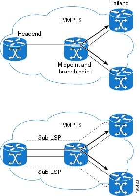
A P2MP TE network contains the following elements, which are shown in the figure below:

  • The headend router, also called the source or ingress router, is where the label switched path (LSP) is initiated. The headend router can also be a branch point, which means the router performs packet replication and the sub-LSPs split into different directions.

  • The midpoint router is where the sub-LSP signaling is processed. The midpoint router can be a branch point.

  • The tailend router, also called the destination, egress, or leaf-node router, is where sub-LSP signaling ends.

  • A bud router is a midpoint and tailend router at the same time.

  • A P2MP tunnel consists of one or more sub-LSPs. All sub-LSPs belonging to the same P2MP tunnel employ the same constraints, protection policies, and so on, which are configured at the headend router.

Figure 1. Basic P2MP TE Tunnels

P2MP TE tunnels build on the features that exist in basic point-to-point TE tunnels. The P2MP TE tunnels have the following characteristics:

  • There is one source (headend) but more than one destination (tailend).

  • They are unidirectional.

  • They are explicitly routed.

  • Multiple sub-LSPs connect the headend router to various tailend routers.

The figure below shows a P2MP TE tunnel that has three destinations.

  • PE1 is the headend router.

  • P01 is a branch point router, where packet replication occurs.

  • PE2, PE3, and PE4 are tailend routers, where the sub-LSP ends.

Between the PE and CE routers, PIM is enabled to exchange multicast routing information with the directly connected customer edge (CE) routers. PIM is not enabled across the P2MP TE tunnel.

Database of Sub-LSP Failure Errors

If any sub-LSP, whether P2MP or P2P, fails to recover after an SSO switchover, the failure is noted in an error database for troubleshooting. You can use theshow ip rsvp high database lsp command to display the error database entries.

Figure 2. Network Topology with P2MP TE Tunnel

How P2MP TE Sub-LSPs Are Signaled

RSVP TE extensions defined in RFC 4875 allow multiple sub-LSPs to be signaled from the headend router. A P2MP TE tunnel consists of multiple sub-LSPs that connect the headend router to various tailend routers.

The headend router sends one RSVP path message to each destination. The tailend router replies with a RESV message. The Label Forwarding Information Base (LFIB) is populated using the RSVP labels allocated by the RESV messages.

The P2MP TE feature does not support signaling of multiple sub-LSPs in the same Path/Resv message. If multiple sub-LSPs occur in the same message, the router sends a PathErr Unknown Objects message, and the Path/Resv message with multiple sub-LSPs is not forwarded.

The tailend routers allocate unreserved labels, which are greater than 15 and do not include implicit or explicit null labels. Using unreserved labels allows IP multicast to perform a Reverse Path Forwarding (RPF) check on the tailend router. Because a sub-LSP tailend router cannot be represented as a regular interface, a special LSP virtual interface (VIF) is automatically created. The LSP VIF represents the originating interface for all IP multicast traffic originating from the P2MP TE tailend router.

The figure below shows the LSP signaling process.

Figure 3. How LSPs Are Signaled

How P2MP TE Traffic Is Forwarded

At the headend of the traffic engineering tunnel, through a static Internet Group Management Protocol (IGMP) group-to-tunnel mapping, IP multicast traffic is encapsulated with a unique MPLS label, which is associated with the P2MP TE tunnel. The multicast traffic is label switched in the P2MP tree and replicated at branch and bud nodes along the P2MP tree. When the labeled packet reaches the tailend (a PE router), the MPLS label is removed and forwarded to the IP multicast tree towards the end point. This process is shown in the figure below.


Note

The P2MP TE feature does not support penultimate-hop popping. Therefore, the egress router must allocate an explicit null or non-null label.


Figure 4. How Packets Traverse the P2MP Tree

When sub-LSPs share a common router (branch point) and use the same ingress interface of the router, the same MPLS label is used for forwarding. The multicast state is built by reusing the MPLS labels at the branch points, as shown in the figure below, where MPLS label 17 is shared by two sub-LSPs that both use router C.

Figure 5. Reusing MPLS Labels in Branch Points

Computing the IGP Path Using Dynamic Paths or Explicit Paths

You can either specify explicit paths or allow paths to be created dynamically. You can also specify bandwidth parameters, which are flooded throughout the MPLS network through existing RSVP-TE extensions to Open Shortest Path First (OSPF) and Integrated Intermediate System-to-Intermediate System (IS-IS).

The MPLS core network uses RSVP to enable end-to-end IP multicast connectivity. The tailend router and the end point router use PIM to exchange multicast routing information with directly connected CE routers. PIM is not configured in the MPLS core.

P2MP TE tunnels can co-exist with regular P2P TE tunnels. Existing path calculation and bandwidth preemption rules apply in this case.

You create IGP paths by enabling dynamic path computation, configuring explicit paths through CLI commands, or using both methods in your P2MP TE network.

  • Dynamic paths are created using Constrained Shortest Path First (CSPF) to determine the best path to a destination. CSPF uses path constraints, such as bandwidth, affinities, priorities, and so on, as part of the computation.

  • Explicit paths allows you to manually specify the path a sub-LSP uses from the headend router to the tailend router. You configure static paths on the headend router.

Remerge Events

When explicit paths are configured with a limited number of equal cost links or paths, two sub-LSPs might connect at a midpoint router through different ingress interfaces, but use the same egress interface. This is called a remerge event, which can cause duplicate MPLS packets. If a router detects a remerge event, it sends a PathErr Routing Problem: Remerge Detected message toward the headend router and the sub-LSPs are not established. With dynamic paths, the router signals a path that avoids a remerge situation.

Crossover Events

With a P2MP tunnel, two sibling sub-LSPs (sub-LSPs that share the same link and label) are said to “cross over” when they have different incoming interfaces and different outgoing interfaces on the same intersecting node. The sibling sub-LSPs neither share input label nor output bandwidth. Avoid configuring crossover LSPs, because they waste bandwidth. However, the duplication of sub-LSPs does not result in an error.

Benefits of MPLS Point-to-Multipoint Traffic Engineering

The P2MP TE feature provides the following benefits:

  • You can configure signaling attributes, such as affinities, administrative metrics, FRR protection, and bandwidth constraints, when you set up P2MP TE sub-LSPs.

  • P2MP TE provides a single point of traffic control. You specify all the signaling and path parameters at the headend router.

  • You can configure explicit paths to optimize traffic distribution.

  • You can enable FRR link protection for P2MP TE sub-LSPs.

  • Protocol Independent Multicast (PIM) is not needed in the MPLS core. Only the non-MPLS interfaces on the tailend routers need to be configured with PIM.

MPLS Point-to-Multipoint Traffic Engineering—Re-optimizing Traffic

A P2MP TE tunnel is operational (up) when the first sub-LSP has been successfully signaled. The P2MP TE tunnel is not operational (down) when all sub-LSPs are down. Certain events can trigger a tunnel re-optimization:

  • One of the sub-LSPs is fast-rerouted to a backup tunnel (for dynamic LSPs).

  • A link is operational. (if the command mpls traffic-eng reoptimize events link-up is configured).

  • A periodic schedule optimization occurs through the mpls traffic-eng reoptimize timers frequency command.

  • The network administrator forces a tunnel optimization through the mpls traffic-eng reoptimize command.

  • A FRR protected interface becomes operational.

  • A non-FRR LSP detects a remerge situation.

When a P2MP tunnel is reoptimized, a new LSP is signaled and traffic is moved to the new LSP.

To determine if a tunnel should be reoptimized, the router considers the following criteria:

  • The router compares the number of reachable destinations between the new tree and current tree. If the new tree contains more reachable destinations than the current tree, the router performs a reoptimization. If the new tree contains fewer reachable destinations than the current tree, then the router keeps the current tree.

  • The router verifies that the same set of reachable destinations in the current tree are also in the new tree. If the new tree does not contain the same destinations, the router keeps the current tree.

  • The router compares the number of destinations in the new tree with the number of destinations in the old tree. If the number of destinations in the new tree is greater than the number of destinations in the current tree, the router switches to the new tree. This guarantees that the new tree will contain all of the existing destinations and more.

  • The router compares the metric between the current and new tree to ensure the new tree and current tree contain the same set of reachable destinations.

  • The router compares the administrative weights of the old tree and the new tree. The router switches to the new tree if the cumulative administrative weight is lower. This step applies as a tie breaker if all the other conditions are the same.

P2MP TE uses make-before-break reoptimization, which uses the following reoptimization process:

  • The new LSP is signaled.

  • The headend router initiates a timer to ensure sufficient time elapses before traffic moves from the current LSP to the new LSP.

  • Traffic is redirected from the current LSP to the new LSP.

  • The timer is started for the purpose of tearing down the old sub-LSPs.

P2P TE Tunnels Coexist with P2MP TE Tunnels

Both P2P and P2MP TE tunnels share the following characteristics:

  • Tunnel bandwidth is configured the same way in both P2P and P2MP tunnels. In P2MP TE tunnels, any bandwidth parameters you configure are applied to all the destination routers. That is, the bandwidth parameters apply to all sub-LSPs. Both P2P and P2MP TE tunnels use the same IGP extension to flood link bandwidth information throughout the network.

  • Tunnel setup and hold priorities, attributes flags, affinity and mask, and administrative weight parameters are configured the same way for P2P and P2MP TE tunnels. P2MP TE tunnel parameters apply to all sub-LSPs.

  • FRR-enabled P2MP sub-LSPs coexist with FRR-enabled P2P LSPs in a network. For P2P TE, node, link, and bandwidth protection is supported. For P2MP TE, only link protection is supported.

  • The method of computing the path dynamically through CSPF is the same for P2P and P2MP TE.

  • Auto-tunnel backup behaves slightly different with P2P and P2MP tunnels. With P2P tunnels, auto-tunnel backup creates two backup tunnels: one for the node protection and one for the link protection. The node protection backup is preferred for P2P LSP protection. With P2MP tunnels, auto-tunnel backup creates one backup tunnel, which is the link protection. Only the link protection backup can be used for P2MP sub-LSPs. The P2P and P2MP tunnels can coexist and be protected.


Note

If P2MP sub-LSPs are signaled from R1->R2->R3 and a P2P tunnel is signaled from R3->R2->R1, then issue the mpls traffic-eng multicast-intact command on R3 in IGP configuration mode under router OSPF or IS-IS to ensure to accommodate multicast traffic for R3's sub-LSPs.


Using FRR to Protect P2MP TE Links

FRR applies to P2P LSPs and P2MP sub-LSPs in the same manner. No new protocol extensions are needed to support P2MP.


Note

For P2MP TE FRR protection, issue the ip routing protocol purge interface command on every penultimate hop router. Otherwise, the router can lose up to 6 seconds worth of traffic during a FRR cutover event.


FRR minimizes interruptions in traffic delivery as a result of link failure. FRR temporarily fast switches LSP traffic to a backup path around a network failure until the headend router signals a new end-to-end LSP.

FRR-enabled P2MP sub-LSPs coexist with FRR-enabled P2P LSPs in a network. For P2MP TE, only link protection is supported. For P2P TE, node, link, and bandwidth protection are supported.

You can configure P2P explicit backup tunnels on point of local repair (PLR) nodes for link protection of P2MP sub-LSPs, similar to LSPs for P2P TE tunnels. You can also enable automatic creation of backup tunnels using the Auto-tunnel Backup feature for P2P TE tunnels. All sibling sub-LSPs that share the same outgoing link are protected by the same backup tunnel. All cousin sub-LSPs that share the same outgoing link can be protected by multiple P2P backup tunnels.

Link protection for a P2MP TE tunnel is illustrated in the figure below, which shows PE1 as the tunnel headend router and PE2, PE3, and PE4 as tunnel tailend routers. The following sub-LSPs are signaled from PE1 in the network:

  • From PE1 to PE2, the sub-LSP travels the following path: PE1 -> P01 -> P02 -> PE2

  • From PE1 to PE3, the sub-LSP travels the following path: PE1 -> P01 -> P03 -> PE3

  • From PE1 to PE4, the sub-LSP travels the following path: PE1 -> P01 -> P04 -> PE4

Node P01 is a branch node that does packet replication in the MPLS forwarding plane; ingress traffic originating from PE1 will be replicated towards routers P02, P03, and P04.

Figure 6. P2MP TE Link Protection Example
To protect the three sub-LSPs, separate point-to-point backup tunnels are signaled. .

Note

Backup tunnels can be created only for links that have an alternative network path.


In this example, router P01 is the Point of Local Repair (PLR) and routers P02, P03, and P04 are Merge Points (MPs).

If a link failure occurs between routers P01 and P04, the following events are triggered:

  1. Router P01 switches traffic destined to PE4 to the backup tunnel associated with P04.

  2. Router P01 sends RSVP path error messages upstream to the P2MP TE headend router PE1. At the same time, P01 and P04 send IGP updates (link state advertisements (LSAs)) to all adjacent IGP neighbors, indicating that the interfaces associated with links P01 through P04 are down.

  3. Upon receiving RSVP path error messages and IGP LSA updates, the headend router triggers a P2MP TE tunnel reoptimization and signals a new sub-LSP. (This occurs if you have specified dynamic path creation.)


Note

If only one sub-LSP becomes active, it remains down until all the sub-LSPs become active.


FRR Failure Detection Mechanisms

To detect link failures in a P2MP TE network, you can use native link and interface failure detection mechanisms, such as bidirectional forwarding detection (BFD), and RSVP hellos.

Bidirectional Forwarding Detection

The MPLS Traffic Engineering: BFD-triggered FRR feature allows you to obtain link by using the Bidirectional Forwarding Detection (BFD) protocol to provide fast forwarding path failure detection times for all media types, encapsulations, topologies, and routing protocols. In addition to fast forwarding path failure detection, BFD provides a consistent failure detection method for network administrators. For more information, see MPLS Traffic Engineering: BFD-triggered Fast Reroute (FRR).

RSVP Hellos

You can configure RSVP hellos on interfaces that do not provide FRR cutover notification during a link failure. The behavior for RSVP hellos is similar for both P2MP TE and P2P TE. For every sub-LSP that has a backup tunnel and has RSVP hellos enabled on its output interface, an RSVP hello instance is created to the neighbor, and the sub-LSP is added to the neighbor's FRR tree in the hello database.

Hello instances between an output interface and neighbor address are shared by fast reroutable P2MP sub-LSPs and P2P LSPs. When a hello session to a neighbor is declared down, all P2P LSPs and P2MP sub-LSPs that are protected by a backup LSP or sub-LSP are switched to their respective backups in the control and data planes.

RSVP hello sessions can also be used to inform the P2MP headend router of failures along a sub-LSP’s path before the RSVP state for the sub-LSP times out, which leads to faster reoptimization. If a sub-LSP cannot select a backup tunnel but has RSVP hellos enabled on its output interface, it looks for a hello instance to its neighbor. If none exists, a hello state time (HST) hello instance is created. If the neighbor goes down, that sub-LSP is torn down. For more information, see MPLS Traffic Engineering (TE) - Fast Reroute (FRR) Link and Node Protection.

Bandwidth Preemption for P2MP TE

Bandwidth Admission Control and preemption mechanisms for P2MP TE sub-LSPs are the same as for LSPs associated with P2P TE tunnels. Any link affinities or constraints defined for the P2MP TE tunnel will be taken into account. The bandwidth signaled for the sub-LSP is removed from the appropriate pool at the appropriate priority, and if needed, lower priority sub-LSPs are preempted with a higher priority sub-LSP.

A P2MP tunnel can be configured to use sub-pool or global-pool bandwidth. When bandwidth is configured, all sub-LSPs of the P2MP tunnel are signaled with the same bandwidth amount and type. If the bandwidth amount or type of a P2MP tunnel is changed, the P2MP tunnel ingress always signals a new set of sub-LSPs (a new P2MP LSP) with the new bandwidth amount and type.

Preemption procedures do not take into account the tunnel type. The same priority rules apply to P2P LSPs and P2MP sub-LSPs. A sub-LSP with a higher setup priority preempts a (sub-)LSP with a lower hold priority, regardless of tunnel type. Thus, a P2MP sub-LSP may preempt a P2P LSP, and vice versa. The determination of which LSPs get preempted is based on hold priority.

You can configure a P2MP TE tunnel to use subpool or global-pool bandwidth. All sub-LSPs associated with the P2MP TE tunnel are signaled with the same bandwidth amount and type. If the bandwidth amount or type is changed, the P2MP tunnel headend router signals a new set of sub-LSPs with the new bandwidth parameters.

Bandwidth sharing is similar for P2MP TE sub-LSPs and P2P TE LSPs. When adding a new sub-LSP, the P2MP-TE headend router determines whether it should share bandwidth with the other sub-LSPs. Two sub-LSPs can share bandwidth as long as they are a “Transit Pair,” meaning the sub-LSPs share the output interface, next-hop and output label.

LSPs and sub-LSPs cannot share bandwidth if they use different bandwidth pools. A change in bandwidth requires reoptimizing P2P or P2MP TE tunnels, which may result in double-counting bandwidth on common links.

Using FRR with Bandwidth Protection has the following requirements:

  • A backup tunnel is required to maintain the service level agreement while the new sub-LSP is created.

  • The PLR router selects the backup tunnel only if the tunnel has enough bandwidth capacity.

  • The backup tunnel might not signal bandwidth.

  • The PLR router decides the best backup path to protect the primary path, based on backup bandwidth and class type.

How to Configure MPLS Point-to-Multipoint Traffic Engineering

Configuring the Headend Routers

The following steps explain how to configure the headend routers for multicast and MPLS point-to-multipoint traffic engineering. As part of the configuration, you specify the tailend routers. You can also specify explicit paths that the tunnel should use or request that the paths be dynamically created or have a combination of dynamic and explicit paths.

Because the configuration of the P2MP TE tunnels is done at the headend router, this feature works best in situations where the destinations do not change often. The P2MP feature does not support dynamic grafting and pruning of sub-LSPs.

SUMMARY STEPS

  1. enable
  2. configure terminal
  3. mpls traffic-eng tunnels
  4. ip multicast-routing [vrf vrf-name ] [distributed ]
  5. interface tunnel number
  6. tunnel mode mpls traffic-eng point-to-multipoint
  7. tunnel destination list mpls traffic-eng {identifier dest-list-id |name dest-list-name }
  8. ip igmp static-group {* | group-address [source {source-address | ssm-map }] | class-map class-map-name }
  9. ip pim {dense-mode [proxy-register {list access-list | route-map map-name }] | passive | sparse-mode | sparse-dense-mode }
  10. exit
  11. mpls traffic-eng destination list {name dest-list-name | identifier dest-list-id }
  12. ip ip-address path-option id {dynamic | explicit {name name | identifier id }
  13. exit
  14. ip explicit-path {name word | identifier number } [enable | disable ]
  15. next-address [loose | strict ] ip-address
  16. end

DETAILED STEPS

  Command or Action Purpose
Step 1

enable

Example:


Router> enable

Enables privileged EXEC mode.

  • Enter your password if prompted.

Step 2

configure terminal

Example:


Router# configure terminal

Enters global configuration mode.

Step 3

mpls traffic-eng tunnels

Example:


Router(config)# mpls traffic-eng tunnels

Globally enables MPLS Traffic Engineering.

  • Also issue this command on each network interface that supports a traffic engineering tunnel.

Step 4

ip multicast-routing [vrf vrf-name ] [distributed ]

Example:


Router(config)# ip multicast-routing distributed

Globally enables IP multicast routing.

Step 5

interface tunnel number

Example:


Router(config)# interface tunnel 100

Configures a tunnel and enters interface configuration mode.

Step 6

tunnel mode mpls traffic-eng point-to-multipoint

Example:


Router(config-if)# tunnel mode mpls traffic-eng point-to-multipoint

Enables MPLS point-to-multipoint traffic engineering on the tunnel.

Step 7

tunnel destination list mpls traffic-eng {identifier dest-list-id |name dest-list-name }

Example:


Router(config-if)# tunnel destination list mpls traffic-eng name in-list-01

Specifies a destination list to specify the IP addresses of point-to-multipoint destinations.

Step 8

ip igmp static-group {* | group-address [source {source-address | ssm-map }] | class-map class-map-name }

Example:


Router(config-if)# ip igmp static-group 239.100.100.101 source 10.11.11.11

Configures static group membership entries on an interface.

  • Configure this on the TE tunnel interface if the source address (S, G) cannot be resolved.

Step 9

ip pim {dense-mode [proxy-register {list access-list | route-map map-name }] | passive | sparse-mode | sparse-dense-mode }

Example:


Router(config-if)# ip pim passive

Enables Protocol Independent Multicast (PIM) on an interface.

  • An interface configured with passive mode does not pass or forward PIM control plane traffic; it passes or forwards only IGMP traffic.

Step 10

exit

Example:


Router(config-if)# exit

Exits interface configuration mode.

Step 11

mpls traffic-eng destination list {name dest-list-name | identifier dest-list-id }

Example:


Router(config)# mpls traffic-eng destination list name in-list-01

Creates a destination list and enters traffic engineering destination list configuration mode.

Step 12

ip ip-address path-option id {dynamic | explicit {name name | identifier id }

Example:


[verbatim ]}

Example:


Router(cfg-te-dest-list)# ip 10.10.10.10 path-option 1 dynamic

Specifies the IP addresses of MPLS point-to-multipoint traffic engineering tunnel destinations.

  • If you use the explicit keyword, you must configure explicit paths, using the ipexplicit-path command.

  • Repeat this step for each destination.

Step 13

exit

Example:


Router(cfg-te-dest-list)# exit

Exits traffic engineering destination list configuration mode.

Step 14

ip explicit-path {name word | identifier number } [enable | disable ]

Example:


Router(config)# ip explicit-path name path1 enable

Specifies the name of an IP explicit path and enters IP explicit path configuration mode.

Step 15

next-address [loose | strict ] ip-address

Example:


Router(cfg-ip-expl-path)# next-address 10.0.0.2

Specifies an explicit path that includes only the addresses specified or loose explicit paths.

Step 16

end

Example:


Router(cfg-ip-expl-path)# end

Exits the current configuration mode and returns to privileged EXEC mode.

Configuring the Midpoint Routers

No special configuration is needed to support the P2MP TE feature on the midpoint routers. The midpoint routers must have Cisco IOS Release 15.5(02)S or later release installed. They must be able to support and implement the P2MP signaling extensions. The MPLS TE configuration of the midpoint routers supports both P2P and P2MP TE. All multicast traffic is label switched. The midpoint routers do not require IPv4 multicast routing or PIM.

All the core interfaces on the mid-point routers, should have this configuration: ip rsvp bandwidth ,mpls traffic-eng tunnels

The IGP, should have this configuration :

router ospf 1 mpls traffic-eng router-id Loopback0 , mpls traffic-eng area 0

For information on configuring MPLS TE, see MPLS Traffic Engineering and Enhancements.

Configuring the Tailend Routers

The tailend routers remove the MPLS labels from the IP multicast packets and send the packets to the MFIB for regular multicast forwarding processing. You must issue the ip mroute command to configure a static route back to the headend router, thus enabling RPF checks.

The following task explains how to configure PIM on the egress interface of the PE router. PIM is needed when the egress PE router is connected to a CE router, which is connected to a LAN where one or more multicast receivers are connected.

If the egress PE router is directly connected to a decoder device/system (e.g., DCM), you must configure Internet Group Management Protocol (IGMP) on the egress interface of the PE router. For more information on configuring IGMP, see Customizing IGMP .

SUMMARY STEPS

  1. enable
  2. configure terminal
  3. ip multicast-routing [vrf vrf-name ] [distributed ]
  4. ip multicast mpls traffic-eng [range access-list-number | access-list-name ]
  5. interface type slot / port
  6. ip pim {dense-mode [proxy-register {list access-list | route-mapmap-name }] | passive | sparse-mode | sparse-dense-mode }
  7. exit
  8. ip mroute [vrf vrf-name ] source-addressmask {fallback-lookup {global | vrf vrf-name } | rpf-address | interface-typeinterface-number } [distance ]
  9. end

DETAILED STEPS

  Command or Action Purpose
Step 1

enable

Example:


Router> enable

Enables privileged EXEC mode.

  • Enter your password if prompted.

Step 2

configure terminal

Example:


Router# configure terminal

Enters global configuration mode.

Step 3

ip multicast-routing [vrf vrf-name ] [distributed ]

Example:


Router(config)# ip multicast-routing 

Enables IP multicast routing globally.

Step 4

ip multicast mpls traffic-eng [range access-list-number | access-list-name ]

Example:


Router(config)# ip multicast mpls traffic-eng

Enables IP multicast routing for MPLS traffic engineering point-to-multipoint tunnels.

Step 5

interface type slot / port

Example:


or 

Example:


              interface
              type slot / port-adapter / port   

Example:


Router(config)# interface ethernet 1/1 

Example:


or 

Example:


Router(config)# interface fastethernet 1/0/0 

Configures an interface type and enters interface configuration mode.

  • The type argument specifies the type of interface to be configured.

  • The slot argument specifies the slot number. Refer to the appropriate hardware manual for slot and port information.

  • The port argument specifies the port number. Refer to the appropriate hardware manual for slot and port information.

  • The port-adapter argument specifies the port adapter number. Refer to the appropriate hardware manual for information about port adapter compatibility.

Step 6

ip pim {dense-mode [proxy-register {list access-list | route-mapmap-name }] | passive | sparse-mode | sparse-dense-mode }

Example:


Router(config-if)# ip pim sparse-dense-mode

Enables Protocol Independent Multicast (PIM) on an interface.

Step 7

exit

Example:


Router(config-if)# exit

Exits interface configuration mode.

Step 8

ip mroute [vrf vrf-name ] source-addressmask {fallback-lookup {global | vrf vrf-name } | rpf-address | interface-typeinterface-number } [distance ]

Example:


Router(config)# ip mroute 10.10.10.10 255.255.255.255 10.11.11.11

Configures a static multicast route (mroute) to the headend router, thus enabling RPF checks.

Step 9

end

Example:


Router(config)# end

(Required) Exits the current configuration mode and returns to privileged EXEC mode.

Configuring FRR with P2MP TE Tunnels

To enable link protection for sub-LSPs associated with a P2MP TE tunnel, perform the following configuration tasks:

  • Enable FRR on the headend router for each P2MP TE tunnel.

  • Configure P2P backup tunnels for network interfaces that require protection.

See MPLS Traffic Engineering—Fast Reroute Link and Node Protection for information and configuration instructions.

Enabling MPLS Traffic Engineering System Logging of Events

MPLS Traffic Engineering system logging allows you to view the following events:

  • Setting up and tearing down of LSPs

  • RSVP Path and RESV requests

  • Sub-LSP status (through path-change messages)

Commands to enable system logging include:

  • mpls traffic-eng logging lsp path-errors

  • mpls traffic-eng logging lsp preemption

  • mpls traffic-eng logging lsp reservation-errors

  • mpls traffic-eng logging lsp setups

  • mpls traffic-eng logging lsp teardowns

  • mpls traffic-eng logging tunnel path change

Verifying the Configuration of MPLS Point-to-Multipoint Traffic Engineering

This section includes the following tasks:

Verifying the Configuration of the Headend Router

At the headend router, use the following steps to verify that:

  • All sub-LSPs are enabled.

  • IP multicast traffic is being forwarded onto the P2MP TE tunnel.

The following commands may also be helpful in the verification of the headend router:

  • show cef path set and show cef path set detail (when the headend router is also a branch point)

  • show ip mfib and show ipmfib verbose

  • show ip rsvp fast-reroute

  • show mpls traffic-eng destination list

  • show mpls traffic-eng fast-reroute database

  • show mpls traffic-eng tunnels with the dest-mode p2mp, detail, andsummary keywords

SUMMARY STEPS

  1. enable
  2. show mpls traffic-eng tunnels brief
  3. show mpls traffic-eng forwarding path-set brief
  4. show mpls traffic-eng forwarding path-set detail
  5. show ip mroute

DETAILED STEPS


Step 1

enable

Issue the enable command to enter privileged EXEC mode.

Step 2

show mpls traffic-eng tunnels brief

Use the show mpls traffic-eng tunnels brief command to display the P2MP TE tunnels originating from the headend router. For example:

Example:

Router# show mpls traffic-eng tunnels brief
signaling Summary:
   LSP Tunnels Process:            running
   Passive LSP Listener:           running
   RSVP Process:                   running
   Forwarding:                     enabled
   Periodic reoptimization:        every 60 seconds, next in 5 seconds
   Periodic FRR Promotion:         Not Running
   Periodic auto-bw collection:    disabled
P2P TUNNELS:
TUNNEL NAME                      DESTINATION      UP IF     DOWN IF   STATE/PROT
p2p-LSP                          10.2.0.1         -         Se2/0     up/up    
Displayed 2 (of 2) heads, 0 (of 0) midpoints, 0 (of 0) tails
P2MP TUNNELS:
                        DEST    CURRENT
INTERFACE   STATE/PROT UP/CFG TUNID LSPID
Tunnel2     up/up      3/10   2     1
Tunnel5     up/down    1/10   5     2
Displayed 2 (of 2) P2MP heads
P2MP SUB-LSPS:
SOURCE          TUNID LSPID   DESTINATION     SUBID     ST UP IF    DOWN IF
10.1.0.1        2     1       10.2.0.1        1         up head     Se2/0  
10.1.0.1        2     1       10.3.0.199      2         up head     Et2/0   
10.1.0.1        2     1       19.4.0.1        2         up head     s2/0   
10.1.0.1        2     2       1 9.4.0.1       2         up head     s2/0   
10.1.0.1        5     2       10.5.0.1        7         up head     e2/0   
100.100.100.100 1     3       200.200.200.200 1         up ge2/0    s2/0
100.100.100.100 1     3       10.1.0.1        1         up e2/0     tail
Displayed 7 P2MP sub-LSPs:
          5 (of 5) heads, 1 (of 1) midpoints, 1 (of 1) tails
Step 3

show mpls traffic-eng forwarding path-set brief

Use the show mpls traffic-eng forwarding path-set brief command to show the sub-LSPs that originate from the headend router. The following example shows three sub-LSPs originating at the headend router and going to different destinations. All the sub-LSPs belong to the same path set, which is a collection of paths. The path set is given a unique ID, which is shown in the PSID column of the example:

Example:

Router# s
how mpls traffic-eng forwarding path-set brief
Sub-LSP Identifier                      
src_lspid[subid]->dst_tunid              InLabel Next Hop      I/F    PSID
---------------------------              ------- ------------- ------ ----
10.0.0.1_19[16]->10.0.0.8_1              none    10.0.1.2      Et0/0  C5000002
10.0.0.1_19[27]->10.0.0.6_1              none    10.0.1.2      Et0/0  C5000002
10.0.0.1_19[31]->10.0.0.7_1              none    10.0.1.2      Et0/0  C5000002
Step 4

show mpls traffic-eng forwarding path-set detail

Use the show mpls traffic-eng forwarding path-set detail command to show more information about the sub-LSPs that originate from the headend router. For example:

Example:

Router# s
how mpls traffic-eng forwarding path-set detail
LSP: Source: 10.1.0.1, TunID: 100, LSPID: 7
  Destination: 10.2.0.1, P2MP Subgroup ID: 1
    Path Set ID: 0x30000001
    OutLabel : Serial2/0, 16
    Next Hop : 10.1.3.2
    FRR OutLabel : Tunnel666, 16 
  LSP: Source: 10.1.0.1, TunID: 100, LSPID: 7
  Destination: 10.3.0.1, P2MP Subgroup ID: 2
    Path Set ID: 0x30000001
    OutLabel : Serial2/0, 16
    Next Hop : 10.1.3.2
    FRR OutLabel : Tunnel666, 16 
Step 5

show ip mroute

Use the show ip mroute command to verify that IP multicast traffic is being forwarded to the P2MP TE tunnel. In the following example, the output shown in bold shows that Tunnel 1 is part of the outgoing interface list for multicast group 232.0.1.4 with a source address of 10.10.10.10:

Example:

Router# show ip mroute
IP Multicast Routing Table
Flags: D - Dense, S - Sparse, B - Bidir Group, s - SSM Group, C - Connected,
       L - Local, P - Pruned, R - RP-bit set, F - Register flag,
       T - SPT-bit set, J - Join SPT, M - MSDP created entry, E - Extranet,
       X - Proxy Join Timer Running, A - Candidate for MSDP Advertisement,
       U - URD, I - Received Source Specific Host Report, 
       Z - Multicast Tunnel, z - MDT-data group sender, 
       Y - Joined MDT-data group, y - Sending to MDT-data group, 
       V - RD & Vector, v - Vector
Outgoing interface flags: H - Hardware switched, A - Assert winner
 Timers: Uptime/Expires
 Interface state: Interface, Next-Hop or VCD, State/Mode
(10.10.10.10, 232.0.1.4), 1d00h/stopped, flags: sTI
  Incoming interface: Ethernet2/0, RPF nbr 10.10.1.1
  Outgoing interface list:
    Tunnel1, Forward/Sparse-Dense, 1d00h/00:01:17
(*, 224.0.1.40), 1d00h/00:02:48, RP 0.0.0.0, flags: DCL
  Incoming interface: Null, RPF nbr 0.0.0.0
  Outgoing interface list:
    Ethernet2/0, Forward/Sparse, 1d00h/00:02:48

Verifying the Configuration of the Midpoint Routers

At the midpoint router, use the following commands to verify that MPLS forwarding occurs. If the midpoint router is branch router, you can also use show mpls forwarding-table labels command to display show specific labels.

SUMMARY STEPS

  1. enable
  2. show mpls forwarding-table

DETAILED STEPS


Step 1

enable

Issue the enable command to enter privileged EXEC mode.

Step 2

show mpls forwarding-table

Use the show mpls forwarding-table command to show that MPLS packets are switched at the midpoint routers. For example:

Example:

Router# show mpls forwarding-table
 
Local      Outgoing   Prefix           Bytes Label   Outgoing   Next Hop    
Label      Label      or Tunnel Id     Switched      interface              
16         16         10.0.0.1 1 [19]  0             Et1/0      10.0.1.30   
Router# show mpls forwarding-table detail
 
Local      Outgoing   Prefix           Bytes Label   Outgoing   Next Hop    
Label      Label      or Tunnel Id     Switched      interface              
16         16         10.0.0.1 1 [19]  0             Et1/0      10.0.1.30   
        MAC/Encaps=14/18, MRU=1500, Label Stack{16}
        AABBCC032800AABBCC0325018847 00010000
        No output feature configured
    Broadcast

Verifying the Configuration of the Tailend Routers

At the tailend router, use the following steps to verify that:

  • MPLS forwarding occurs.

  • IP multicast forwarding occurs.

You can also use the show ip mfib , showmpls traffic-eng destination list , and show mpls traffic-eng tunnels dest-mode p2mp commands for verification.

SUMMARY STEPS

  1. enable
  2. show mpls forwarding-table
  3. show ip mroute

DETAILED STEPS


Step 1

enable

Issue the enable command to enter privileged EXEC mode.

Step 2

show mpls forwarding-table

Use the show mpls forwarding-table command to show that MPLS labeled packets are forwarded from the tailend router without any label.

Example:

Router# show mpls forwarding-table
 
Local      Outgoing   Prefix           Bytes Label   Outgoing   Next Hop    
Label      Label      or Tunnel Id     Switched      interface              
17    [T]  No Label   10.0.0.1 1 [19]  342           aggregate  
[T]     Forwarding through a LSP tunnel.
Router# show mpls forwarding-table detail
Local      Outgoing   Prefix           Bytes Label   Outgoing   Next Hop    
Label      Label      or Tunnel Id     Switched      interface              
17         No Label   10.0.0.1 1 [19]  342           aggregate  
        MAC/Encaps=0/0, MRU=0, Label Stack{}, via Ls0
Step 3

show ip mroute

Use the show ip mroute command to display IP multicast traffic. In the following example, the output in bold shows the incoming interface is Lspvif0 and the outgoing interface is Ethernet1/0 is for multicast group 232.0.1.4 with source address 10.10.10.10:

Example:

Router# show ip mroute
IP Multicast Routing Table
...
(*, 232.0.1.4), 1d02h/stopped, RP 0.0.0.0, flags: SP
  Incoming interface: Null, RPF nbr 0.0.0.0
  Outgoing interface list: Null
(10.10.10.10, 232.0.1.4), 00:01:51/00:01:38, flags: 
  Incoming interface: Lspvif0, RPF nbr 10.0.0.1, Mroute
  Outgoing interface list:
    Ethernet1/0, Forward/Sparse, 00:01:51/00:02:37
(*, 224.0.1.40), 1d02h/00:02:57, RP 0.0.0.0, flags: DCL
  Incoming interface: Null, RPF nbr 0.0.0.0
  Outgoing interface list:
    Ethernet1/0, Forward/Sparse, 1d02h/00:02:57

Configuration Examples for MPLS Point-to-Multipoint Traffic Engineering

The following examples show point-to-multipoint traffic engineering configurations on the headend router (PE5), a midpoint router (P1), and a tailend router (PE1):

Figure 7. Sample MPLS TE P2MP TE Topology

Example Configuration of the Headend Router (PE5)

In the following example configuration of the headend router, note the following:

  • IPv4 multicast routing is enabled with the ipmulticast-routing command.

  • Two destination lists are specified, one for dynamic paths and one for explicit paths. The destination list specifies one path-option per destination.

  • Thetunnelmodemplstraffic-engpoint-to-multipoint command enables the P2MP tunnel.

  • On the tunnel interfaces, the ippimpassive command is used.

  • On the non-MPLS interfaces, the ippimsparse-mode command is used.

  • The ipigmpstatic-group commands map the multicast groups to the P2MP tunnel.

  • FRR is enabled on the router, with tunnel 3 as the backup path. An explicit path called PE5->P1-BKUP provides the alternative path.


hostname [PE5]
!
boot-start-marker
boot-end-marker
!
!
no aaa new-model
clock timezone PST -8
ip subnet-zero
ip source-route
ip cef
no ip domain lookup
!
ip multicast-routing 
!
no ipv6 cef
mpls traffic-eng tunnels
!
mpls traffic-eng destination list name P2MP-DYN-DST-LIST
    ip 172.16.255.1 path-option 10 dynamic
    ip 172.16.255.2 path-option 10 dynamic
    ip 172.16.255.3 path-option 10 dynamic
    ip 172.16.255.4 path-option 10 dynamic
!
mpls traffic-eng destination list name P2MP-EXCIT-DST-LIST
    ip 172.16.255.1 path-option 10 explicit identifier 101
    ip 172.16.255.2 path-option 10 explicit identifier 102
    ip 172.16.255.3 path-option 10 explicit identifier 103
    ip 172.16.255.4 path-option 10 explicit identifier 104
!
multilink bundle-name authenticated
!
interface Tunnel1
 description PE5->PE1,PE2,PE3,PE4-DYN
 ip unnumbered Loopback0
 ip pim passive
 ip igmp static-group 232.0.1.4 source 192.168.5.255
 ip igmp static-group 232.0.1.3 source 192.168.5.255
 ip igmp static-group 232.0.1.2 source 192.168.5.255
 ip igmp static-group 232.0.1.1 source 192.168.5.255
 tunnel mode mpls traffic-eng point-to-multipoint
 tunnel destination list mpls traffic-eng name P2MP-DYN-DST-LIST
 tunnel mpls traffic-eng priority 7 7
 tunnel mpls traffic-eng bandwidth 10000
!
interface Tunnel2
 description PE5->PE1,PE2,PE3,PE4-EXCIT
 ip unnumbered Loopback0
 ip pim passive
 ip igmp static-group 232.0.1.8 source 192.168.5.255
 ip igmp static-group 232.0.1.7 source 192.168.5.255
 ip igmp static-group 232.0.1.6 source 192.168.5.255
 ip igmp static-group 232.0.1.5 source 192.168.5.255
 tunnel mode mpls traffic-eng point-to-multipoint
 tunnel destination list mpls traffic-eng name P2MP-EXCIT-DST-LIST
 tunnel mpls traffic-eng priority 7 7
 tunnel mpls traffic-eng bandwidth 20000
 tunnel mpls traffic-eng fast-reroute
!
interface Tunnel3
 description PE5->P1
 ip unnumbered Loopback0
 tunnel mode mpls traffic-eng
 tunnel destination 172.16.255.201
 tunnel mpls traffic-eng path-option 10 explicit name PE5->P1-BKUP
!
interface Loopback0
 ip address 172.16.255.5 255.255.255.255
!
interface Ethernet0/0
 description CONNECTS to CE5
 ip address 192.168.5.1 255.255.255.252
 ip pim sparse-mode
!
interface Ethernet1/0
 description CONNECTS TO P1
 bandwidth 1000000
 ip address 172.16.0.13 255.255.255.254
 ip router isis 
 mpls traffic-eng tunnels
 mpls traffic-eng backup-path Tunnel3
 isis network point-to-point 
 ip rsvp bandwidth percent 100
!
interface Ethernet2/0
 description CONNECTS TO P2
 bandwidth 1000000
 ip address 172.16.0.14 255.255.255.254
 ip router isis 
 mpls traffic-eng tunnels
 isis network point-to-point 
 ip rsvp bandwidth percent 100
!
router isis
 net 49.0001.1720.1625.5005.00
 is-type level-2-only
 metric-style wide
 passive-interface Loopback0
 mpls traffic-eng router-id Loopback0
 mpls traffic-eng level-2
!
!
ip classless
!
no ip http server
!
ip pim ssm default
!
ip explicit-path identifier 101 enable
 next-address 172.16.0.12
 next-address 172.16.192.0
 next-address 172.16.0.0
!
ip explicit-path identifier 102 enable
 next-address 172.16.0.12
 next-address 172.16.192.0
 next-address 172.16.0.3
!
ip explicit-path identifier 103 enable
 next-address 172.16.0.12
 next-address 172.16.192.0
 next-address 172.16.192.6
 next-address 172.16.0.6
!
ip explicit-path identifier 104 enable
 next-address 172.16.0.12
 next-address 172.16.192.0
 next-address 172.16.192.6
 next-address 172.16.0.9
!
ip explicit-path name PE5->P1-BKUP enable
 next-address 172.16.0.15
 next-address 172.16.192.2

Example Configuration of the Midpoint Router (P1)

In the following example configuration of the midpoint router, note the following:

  • MPLS Traffic Engineering is enabled both globally and on the interface connecting to other core routers.

  • MPLE TE extensions are enabled through the mplstraffic-engrouter-id and mplstraffic-englevel commands.


hostname [P1]
!
no aaa new-model
clock timezone PST -8
ip subnet-zero
ip source-route
ip cef
no ip domain lookup
!
no ipv6 cef
mpls traffic-eng tunnels
multilink bundle-name authenticated
!
interface Loopback0
 ip address 172.16.255.201 255.255.255.255
!
interface Ethernet0/0
 description CONNECTS TO P2
 bandwidth 1000000
 ip address 172.16.192.2 255.255.255.254
 ip router isis 
 mpls traffic-eng tunnels
 isis network point-to-point 
 ip rsvp bandwidth percent 100
!
interface Ethernet0/1
 no ip address
 shutdown
!
interface Ethernet0/2
 no ip address
 shutdown
!
interface Ethernet0/3
 no ip address
 shutdown
!
interface Ethernet1/0
 description CONNECTS TO P3
 bandwidth 1000000
 ip address 172.16.192.1 255.255.255.254
 ip router isis 
 mpls traffic-eng tunnels
 isis network point-to-point 
 ip rsvp bandwidth percent 100
!
interface Ethernet2/0
 description CONNECTS TO PE5
 bandwidth 1000000
 ip address 172.16.0.12 255.255.255.254
 ip router isis 
 mpls traffic-eng tunnels
 isis network point-to-point 
 ip rsvp bandwidth percent 100
!
router isis
 net 49.0001.1720.1625.5201.00
 is-type level-2-only
 metric-style wide
 passive-interface Loopback0
 mpls traffic-eng router-id Loopback0
 mpls traffic-eng level-2
!
ip classless
!
no ip http server

Example Configuration of the Tailend Router (PE1)

In the following example configuration of the tailend router, note the following:

  • IPv4 multicast routing is enabled with the ipmulticast-routing command.

  • On the non-MPLS interfaces, the ippimsparse-mode command is used.

  • The ipmulticastmpls commands enable multicast routing of traffic.


hostname [PE1]
!
no aaa new-model
clock timezone PST -8
ip subnet-zero
ip source-route
ip cef
no ip domain lookup
!
ip multicast-routing 
!
no ipv6 cef
mpls traffic-eng tunnels
multilink bundle-name authenticated
!
interface Loopback0
 ip address 172.16.255.1 255.255.255.255
!
interface Ethernet0/0
 description CONNECTS TO CE1
 ip address 192.168.1.1 255.255.255.252
 ip pim sparse-mode
!
interface Ethernet0/3
 description CONNECTS TO P3
 bandwidth 155000
 no ip address
 shutdown
 mpls traffic-eng tunnels
 ip rsvp bandwidth 155000
!
interface Ethernet1/0
 description CONNECTS TO PE2
 bandwidth 1000000
 ip address 172.16.0.5 255.255.255.254
 ip router isis 
 mpls traffic-eng tunnels
 isis network point-to-point 
 ip rsvp bandwidth percent 100
!
interface Ethernet2/0
 description CONNECTS TO P3
 bandwidth 1000000
 ip address 172.16.0.0 255.255.255.254
 ip router isis 
 mpls traffic-eng tunnels
 isis network point-to-point 
 ip rsvp bandwidth percent 100
!
router isis
 net 49.0001.1720.1625.5001.00
 is-type level-2-only
 metric-style wide
 passive-interface Loopback0
 mpls traffic-eng router-id Loopback0
 mpls traffic-eng level-2
!
!
ip classless
!
no ip http server
!
ip multicast mpls traffic-eng
ip pim ssm default
ip mroute 192.168.5.0 255.255.255.0 172.16.255.5