Prerequisites for MPLS Multilink PPP Support
-
Multiprotocol Label Switching (MPLS) must be enabled on provider edge (PE) and provider (P) devices
The documentation set for this product strives to use bias-free language. For the purposes of this documentation set, bias-free is defined as language that does not imply discrimination based on age, disability, gender, racial identity, ethnic identity, sexual orientation, socioeconomic status, and intersectionality. Exceptions may be present in the documentation due to language that is hardcoded in the user interfaces of the product software, language used based on RFP documentation, or language that is used by a referenced third-party product. Learn more about how Cisco is using Inclusive Language.
The MPLS Multilink PPP Support feature ensures that MPLS Layer 3 Virtual Private Networks (VPNs) with quality of service (QoS) can be enabled for bundled links. This feature supports Multiprotocol Label Switching (MPLS) over Multilink PPP (MLP) links in the edge (provider edge [PE]-to-customer edge [CE]) or in the MPLS core (PE-to-PE and PE-to-provider [P] device).
Service providers that use relatively low-speed links can use MLP to spread traffic across them in their MPLS networks. Link fragmentation and interleaving (LFI) should be deployed in the CE-to-PE link for efficiency, where traffic uses a lower link bandwidth (less than 768 kbps). The MPLS Multilink PPP Support feature can reduce the number of Interior Gateway Protocol (IGP) adjacencies and facilitate load sharing of traffic.
Multiprotocol Label Switching (MPLS) must be enabled on provider edge (PE) and provider (P) devices
Only 168 multilink bundles can be created per the OC-3 interface module on the router.
The maximum number of members per multilink bundle is 16.
Links in multilink bundles must be on the same interface module.
On the 8 T1/E1, a maximum of 8 bundles can be supported.
On the 16T1/E1, a maximum of 16 bundles can be supported.
On the 32 T1/E1, a maximum of 32 bundles can be supported.
For information on how to configure, Protocol-Field-Compression (PFC) and Address-and-Control-Field-Compression (AFC), see Configuring PPP and Multilink PPP on the Cisco ASR 903 Router.
The table below lists Multiprotocol Label Switching (MPLS) Layer 3 Virtual Private Network (VPN) features supported for Multilink PPP (MLP) and indicates if the feature is supported on customer edge-to-provider edge (CE-to-PE) links, PE-to-provider (P) links, and Carrier Supporting Carrier (CSC) CE-to-PE links.
|
MPLS L3 VPN Feature |
CE-to-PE Links |
PE-to-P Links |
CSC CE-to-PE Links |
|---|---|---|---|
|
Static routes |
Supported |
Not supported |
Not supported |
|
External Border Gateway Protocol (eBGP) |
Supported |
Not applicable to this configuration |
Supported |
|
Intermediate System-to-Intermediate System (IS-IS) |
Not supported |
Supported |
Not supported |
|
Open Shortest Path First (OSPF) |
Supported |
Supported |
Not supported |
|
Enhanced Interior Gateway Routing Protocol (EIGRP) |
Supported |
Supported |
Not supported |
|
Interprovider interautonomous (Inter-AS) VPNs (with Label Distribution Protocol [LDP]) |
Not applicable to this configuration |
Supported (MLP between Autonomous System Boundary Routers [ASBRs]) |
Not applicable to this configuration |
|
Inter-AS VPNs with IPv4 Label Distribution |
Not applicable to this configuration |
Supported (MLP between ASBRs) |
Not applicable to this configuration |
|
CSC VPNs (with LDP) |
Not supported |
Not applicable to this configuration |
Supported |
|
CSC VPNs with IPv4 label distribution |
Supported |
Not applicable to this configuration |
Supported |
|
External and internal BGP (eiBGP) Multipath |
Not supported |
Not supported |
Not applicable to this configuration |
|
Internal BGP (iBGP) Multipath |
Not applicable to this configuration |
Not supported |
Not applicable to this configuration |
|
eBGP Multipath |
Not supported |
Not supported |
Not supported |
The table below lists the Multiprotocol Label Switching (MPLS) quality of service (QoS) features supported for Multilink PPP (MLP) and indicates if the feature is supported on customer edge-to-provider edge (CE-to-PE) links, PE-to-provider (P) links, and Carrier Supporting Carrier (CSC) CE-to-PE links.
|
MPLS QoS Feature |
CE-to-PE Links |
PE-to-P Links |
CSC CE-to-PE Links |
|---|---|---|---|
|
Default copy of IP Precedence to EXP bits and the reverse |
Supported |
Not supported |
Not supported |
|
Set MPLS EXP bits using the modular QoS Command-Line Interface (MQC) |
Supported |
Supported |
Supported |
|
Matching on MPLS EXP using MQC |
Supported |
Supported |
Supported |
|
Low Latency Queueing (LLQ)/Class-Based Weighted Fair Queueing (CBWFQ) support |
Supported |
Supported |
Supported |
|
Weighted Random Early Detection (WRED) based on EXP bits using MQC |
Supported |
Supported |
Supported |
|
Policer with EXP bit-marking using MQC-3 action |
Supported |
Supported |
Supported |
|
Support for EXP bits in MPLS accounting |
Supported |
Supported |
Supported |
The figure below shows a typical Multiprotocol Label Switching (MPLS) network in which the provider edge (PE) device is responsible for label imposition (at ingress) and disposition (at egress) of the MPLS traffic.
In this topology, Multilink PPP (MLP) is deployed on the PE-to-customer edge (CE) links. The Virtual Private Network (VPN) routing and forwarding instance (VRF) interface is in a multilink bundle. There is no MPLS interaction with MLP; all packets coming into the MLP bundle are IP packets.
The PE-to-CE routing protocols that are supported for the MPLS Multilink PPP Support feature are external Border Gateway Protocol (eBGP), Open Shortest Path First (OSPF), and Enhanced Interior Gateway Routing Protocol (EIGRP). Static routes are also supported between the CE and PE devices.
Quality of service (QoS) features that are supported for the MPLS Multilink PPP Support feature on CE-to-PE links are link fragmentation and interleaving (LFI), compressed Real-Time Transport Protocol (cRTP), policing, marking, and classification.
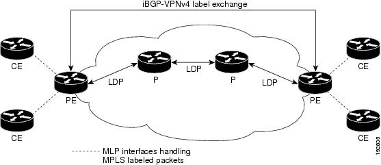
The figure below shows a sample topology in which Multiprotocol Label Switching (MPLS) is deployed over Multilink PPP (MLP) on provider edge-to-provider (PE-to-P) and P-to-P links. Enabling MPLS on MLP for PE-to-P links is similar to enabling MPLS on MLP for P-to-P links.

You employ MLP in the PE-to-P or P-to-P links primarily so that you can reduce the number of Interior Gateway Protocol (IGP) adjacencies and facilitate the load sharing of traffic.
In addition to requiring MLP on the PE-to-P links, the MPLS Multilink PPP Support feature requires the configuration of an IGP routing protocol and the Label Distribution Protocol (LDP).
The figure below shows a typical Multiprotocol Label Switching (MPLS) Virtual Private Network (VPN) Carrier Supporting Carrier (CSC) network where Multilink PPP (MLP) is configured on the CSC customer edge (CE)-to-provider edge (PE) links.

The MPLS Multilink PPP Support feature supports MLP between CSC-CE and CSC-PE links with the Label Distribution Protocol (LDP) or with external Border Gateway Protocol (eBGP) IPv4 label distribution. This feature also supports link fragmentation and interleaving (LFI) for an MPLS VPN CSC configuration. The figure below shows all MLP links that this feature supports for CSC configurations.

The figure below shows a typical Multiprotocol Label Switching (MPLS) Virtual Private Network (VPN) interautonomous system (Inter-AS) network where Multilink PPP (MLP) is configured on the provider edge-to-customer edge (PE-to-CE) links.

The MPLS Multilink PPP Support feature supports MLP between Autonomous System Boundary Router (ASBR) links for Inter-AS VPNs with Label Distribution Protocol (LDP) and with external Border Gateway Protocol (eBGP) IPv4 label distribution.
The tasks in this section can be performed on customer edge-to-provider edge (CE-to-PE) links, PE-to-provider (P) links, P-to-P links, and Carrier Supporting Carrier (CSC) CE-to-PE links.
Perform this task to create a multilink bundle for the MPLS Multilink PPP Support feature. This multilink bundle can reduce the number of Interior Gateway Protocol (IGP) adjacencies and facilitate load sharing of traffic.
| Command or Action | Purpose | |
|---|---|---|
| Step 1 |
enable Example: |
Enables privileged EXEC mode.
|
| Step 2 |
configure terminal Example: |
Enters global configuration mode. |
| Step 3 |
interface multilink group-number Example: |
Creates a multilink bundle and enters multilink interface configuration mode.
|
| Step 4 |
ip address address mask [secondary] Example: |
Sets a primary or secondary IP address for an interface.
This command is used to assign an IP address to the multilink interface. |
| Step 5 |
encapsulation encapsulation-type Example: |
Sets the encapsulation method as PPP to be used by the interface.
|
| Step 6 |
ppp multilink Example: |
Enables MLP on an interface. |
| Step 7 |
mpls ip Example: |
Enables label switching on the interface. |
| Step 8 |
end Example: |
Returns to privileged EXEC mode. |
| Command or Action | Purpose | |
|---|---|---|
| Step 1 |
enable Example: |
Enables privileged EXEC mode.
|
| Step 2 |
configure terminal Example: |
Enters global configuration mode. |
| Step 3 |
controller {t1 | e1 } slot/port Example: |
Configures a T1 or E1 controller and enters controller configuration mode.
|
| Step 4 |
channel-group channel-number timeslots Example: |
Defines the time slots that belong to each T1 or E1 circuit.
|
| Step 5 |
exit Example: |
Returns to global configuration mode. |
| Step 6 |
interface serial slot/subslot / port : channel-group Example: |
Configures a serial interface for a Cisco 7500 series router with channelized T1 or E1 and enters interface configuration mode.
|
| Step 7 |
ip route-cache [cef | distributed] Example: |
Controls the use of switching methods for forwarding IP packets.
|
| Step 8 |
no ip address Example: |
Removes any specified IP address. |
| Step 9 |
keepalive [period [retries]] Example: |
Enables keepalive packets and specifies the number of times that the Cisco software tries to send keepalive packets without a response before bringing down the interface or before bringing the tunnel protocol down for a specific interface.
If you are using this command with a tunnel interface, the command specifies the number of times that the device continues to send keepalive packets without a response before bringing the tunnel interface protocol down. |
| Step 10 |
encapsulation encapsulation-type Example: |
Sets the encapsulation method used by the interface.
|
| Step 11 |
ppp multilink group group-number Example: |
Restricts a physical link to join only one designated multilink group interface.
|
| Step 12 |
ppp multilink Example: |
Enables MLP on the interface. |
| Step 13 |
ppp authentication chap Example: |
(Optional) Enables Challenge Handshake Authentication Protocol (CHAP) authentication on the serial interface. |
| Step 14 |
end Example: |
Returns to privileged EXEC mode. |
| Step 1 |
enable Enables privileged EXEC mode. Enter your password if prompted. Example: |
| Step 2 |
show ip interface brief Verifies logical and physical Multilink PPP (MLP) interfaces. Example: |
| Step 3 |
show ppp multilink Verifies that you have created a multilink bundle. Example: |
| Step 4 |
show ppp multilink interface interface-bundle Displays information about a specific MLP interface. Example: |
| Step 5 |
show interface type number Displays information about serial interfaces in your configuration. Example:You can also use the show interface command to display information about the multilink interface: Example: |
| Step 6 |
show mpls forwarding-table Displays contents of the Multiprotocol Label Switching (MPLS) Label Forwarding Information Base (LFIB). Look for information on multilink interfaces associated with a point2point next hop. Example:Use the show ip bgp vpnv4 command to display VPN address information from the Border Gateway Protocol (BGP) table. Example: |
| Step 7 |
exit Returns to user EXEC mode. Example: |
The following examples show sample configurations on a Carrier Supporting Carrier (CSC) network. The configuration of MLP on an interface is the same for provider edge-to-customer edge (PE-to-CE) links, PE-to-provider (P) links, and P-to-P links.
The following example shows how to configure for Multiprotocol Label Switching (MPLS) Carrier Supporting Carrier (CSC) provider edge (PE) device.
!
mpls label protocol ldp
ip cef
ip vrf vpn2
 rd 200:1
 route-target export 200:1
 route-target import 200:1
!

controller T1 0/0/1
framing esf
clock source internal
linecode b8zs
channel-group 1 timeslots 1-24
!
interface Serial0/0:1
 no ip address
 encapsulation ppp

 ppp multilink
 ppp multilink group 1

interface Multilink1
 ip vrf forwarding vpn2
 ip address 10.35.0.2 255.0.0.0
 no peer neighbor-route
 load-interval 30
 ppp multilink
 ppp multilink interleave
 ppp multilink group 1
mpls ip
mpls label protocol ldp
!
!
router ospf 200
 log-adjacency-changes
 auto-cost reference-bandwidth 1000
 redistribute connected subnets
 passive-interface Multilink1
 network 10.0.0.7 0.0.0.0 area 200
 network 10.31.0.0 0.255.255.255 area 200
!
!
 router bgp 200
 no bgp default ipv4-unicast
 bgp log-neighbor-changes
 neighbor 10.0.0.11 remote-as 200
 neighbor 10.0.0.11 update-source Loopback0
 !
 address-family vpnv4
 neighbor 10.0.0.11 activate
 neighbor 10.0.0.11 send-community extended
 bgp scan-time import 5
 exit-address-family
 !
 address-family ipv4 vrf vpn2
 redistribute connected
 neighbor 10.35.0.1 remote-as 300
 neighbor 10.35.0.1 activate
 neighbor 10.35.0.1 as-override
 neighbor 10.35.0.1 advertisement-interval 5
 no auto-summary
 no synchronization
exit-address-familyThe following example shows how to create a multilink bundle for the MPLS Multilink PPP Support feature:
Device(config)# interface multilink 1
Device(config-if)# ip address 10.0.0.0 10.255.255.255
Device(config-if)# encapsulation ppp
Device(config-if)# ppp chap hostname group 1
Device(config-if)# ppp multilink
Device(config-if)# ppp multilink group 1
Device(config-if)# mpls ip
Device(config-if)# mpls label protocol ldpThe following example shows how to create four multilink interfaces with Cisco Express Forwarding switching and Multilink PPP (MLP) enabled. Each of the newly created interfaces is added to a multilink bundle.
interface multilink1
 ip address 10.0.0.0 10.255.255.255
 ppp chap hostname group 1
 ppp multilink
 ppp multilink group 1
mpls ip
mpls label protocol ldp

interface serial 0/0/0/:1
 no ip address
 encapsulation ppp
 ip route-cache cef
 no keepalive
 ppp multilink
 ppp multilink group 1

 no ip address
 encapsulation ppp
 ip route-cache cef
 no keepalive
 ppp chap hostname group 1
 ppp multilink
 ppp multilink group 1

 no ip address
 encapsulation ppp
 ip route-cache cef
 no keepalive
 ppp chap hostname group 1
 ppp multilink
 ppp multilink group 1

 no ip address
 encapsulation ppp
 ip route-cache cef
 no keepalive
 ppp chap hostname group 1
 ppp multilink
ppp multilink group 1 Feedback