Pseudowire Overview
The following sections provide an overview of pseudowire support on the router.
-
BGP PIC with TDM Pseudowire is supported on the ASR 900 router with RSP2 module.
-
BGP PIC for Pseudowires, with MPLS Traffic Engineering is supported on the ASR 900 router with RSP1 and RSP2 modules.
Starting Cisco IOS XE Release 3.18.1SP, Pseudowire Uni-directional Active-Active is supported on the RSP1 and RSP3 modules.
Limitations
If you are running Cisco IOS XE Release 3.17S and later releases, the following limitations apply:
-
Channel associated signaling (CAS) is not supported on the T1/E1 and OC-3 interface modules on the router.
-
BGP PIC is not supported for MPLS/LDP over MLPPP and POS in the core.
-
BGP PIC is not supported for Multi-segment Pseudowire or Pseudowire switching.
-
BGP PIC is not supported for VPLS and H-VPLS.
-
BGP PIC is not supported for IPv6.
-
If BGP PIC is enabled, Multi-hop BFD should not be configured using the bfd neighbor fall-over r bfd command.
-
If BGP PIC is enabled, neighbor ip-address weight weight command should not be configured.
-
If BGP PIC is enabled, bgp nexthop trigger delay 6 under the address-family ipv4 command and bgp nexthop trigger delay 7 under the address-family vpnv4 command should be configured. For information on the configuration examples for BGP PIC–TDM, see Example: BGP PIC with TDM-PW Configuration.
-
If BGP PIC is enabled and the targeted LDP for VPWS cross-connect services are established over BGP, perform the following tasks:
-
configure Pseudowire-class (pw-class) with encapsulation "mpls"
-
configure no status control-plane route-watch under the pw-class
-
associate the pw-class with the VPWS cross-connect configurations
-
If you are running Cisco IOS-XE 3.18S, the following restrictions apply for BGP PIC with MPLS TE for TDM Pseudowire:
-
MPLS TE over MLPPP and POS in the core is not supported.
-
Co-existence of BGP PIC with MPLS Traffic Engineering Fast Reroute (MPLS TE FRR) is not supported.
The following restrictions are applicable only if the BFD echo mode is enabled on the Ethernet interface carrying CEM or TDM traffic:
-
When the TDM interface module is present in anyone of the slot—0, 1, or 2, then the corresponding Ethernet interface module carrying the CEM traffic should also be present in one of these slots.
-
When the TDM interface moduleis present in anyone of the slot—3, 4, or 5, then the corresponding Ethernet interface module carrying the CEM traffic should also be present in one of these slots.
Circuit Emulation Overview
Circuit Emulation (CEM) is a technology that provides a protocol-independent transport over IP networks. It enables proprietary or legacy applications to be carried transparently to the destination, similar to a leased line.
The Cisco ASR 903 Series Router supports two pseudowire types that utilize CEM transport: Structure-Agnostic TDM over Packet (SAToP) and Circuit Emulation Service over Packet-Switched Network (CESoPSN). The following sections provide an overview of these pseudowire types.
Starting with Cisco IOS XE Release 3.15, the 32xT1E1 and 8x T1/E1 interface modules support CEM CESoP and SATOP configurations with fractional timeslots.
With the 32xT1/E1 and 8xT1/E1 interface modules, the channelized CEM circuits configured under a single port (fractional timeslot) cannot be deleted or modified, unless the circuits created after the first CEM circuits are deleted or modified.
The following CEM circuits are supported on the 32xT1/E1 interface module:
T1 mode
-
192 CESOP circuits with fractional timeslot
-
32 CESOP circuit full timeslot
-
32 SATOP circuits
E1 mode
-
256 CESOP circuit with fractional timeslot
-
32 CESOP circuit full timeslot
-
32 SATOP circuit
 Note |
CEM pseudowire with local loopback at the CEM sides of PEs results in propagating AIS and L-bit alarms. The L-bit packets are dropped for the following interface module:
|
Structure-Agnostic TDM over Packet
SAToP encapsulates time division multiplexing (TDM) bit-streams (T1, E1, T3, E3) as PWs over public switched networks. It disregards any structure that may be imposed on streams, in particular the structure imposed by the standard TDM framing.
The protocol used for emulation of these services does not depend on the method in which attachment circuits are delivered to the provider edge (PE) devices. For example, a T1 attachment circuit is treated the same way for all delivery methods, including copper, multiplex in a T3 circuit, a virtual tributary of a SONET/SDH circuit, or unstructured Circuit Emulation Service (CES).
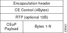
In SAToP mode the interface is considered as a continuous framed bit stream. The packetization of the stream is done according to IETF RFC 4553. All signaling is carried out transparently as a part of a bit stream. Unstructured SAToP Mode Frame Format shows the frame format in Unstructured SAToP mode.

#con_1729521__ shows the payload and jitter limits for the T1 lines in the SAToP frame format.
|
Maximum Payload |
Maximum Jitter |
Minimum Jitter |
Minimum Payload |
Maximum Jitter |
Minimum Jitter |
|---|---|---|---|---|---|
|
960 |
320 |
10 |
192 |
64 |
2 |
#con_1729521__ shows the payload and jitter limits for the E1 lines in the SAToP frame format.
|
Maximum Payload |
Maximum Jitter |
Minimum Jitter |
Minimum Payload |
Maximum Jitter |
Minimum Jitter |
|---|---|---|---|---|---|
|
1280 |
320 |
10 |
256 |
64 |
2 |
For instructions on how to configure SAToP, see Configuring Structure-Agnostic TDM over Packet (SAToP).
Circuit Emulation Service over Packet-Switched Network
CESoPSN encapsulates structured TDM signals as PWs over public switched networks (PSNs). It complements similar work for structure-agnostic emulation of TDM bit streams, such as SAToP. Emulation of circuits saves PSN bandwidth and supports DS0-level grooming and distributed cross-connect applications. It also enhances resilience of CE devices due to the effects of loss of packets in the PSN.
CESoPSN identifies framing and sends only the payload, which can either be channelized T1s within DS3 or DS0s within T1. DS0s can be bundled to the same packet. The CESoPSN mode is based on IETF RFC 5086.
Each supported interface can be configured individually to any supported mode. The supported services comply with IETF and ITU drafts and standards.
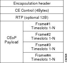
Structured CESoPSN Mode Frame Format shows the frame format in CESoPSN mode.

Table 1 shows the payload and jitter for the DS0 lines in the CESoPSN mode.
|
DS0 |
Maximum Payload |
Maximum Jitter |
Minimum Jitter |
Minimum Payload |
Maximum Jitter |
Minimum Jitter |
|---|---|---|---|---|---|---|
|
1 |
40 |
320 |
10 |
32 |
256 |
8 |
|
2 |
80 |
320 |
10 |
32 |
128 |
4 |
|
3 |
120 |
320 |
10 |
33 |
128 |
4 |
|
4 |
160 |
320 |
10 |
32 |
64 |
2 |
|
5 |
200 |
320 |
10 |
40 |
64 |
2 |
|
6 |
240 |
320 |
10 |
48 |
64 |
2 |
|
7 |
280 |
320 |
10 |
56 |
64 |
2 |
|
8 |
320 |
320 |
10 |
64 |
64 |
2 |
|
9 |
360 |
320 |
10 |
72 |
64 |
2 |
|
10 |
400 |
320 |
10 |
80 |
64 |
2 |
|
11 |
440 |
320 |
10 |
88 |
64 |
2 |
|
12 |
480 |
320 |
10 |
96 |
64 |
2 |
|
13 |
520 |
320 |
10 |
104 |
64 |
2 |
|
14 |
560 |
320 |
10 |
112 |
64 |
2 |
|
15 |
600 |
320 |
10 |
120 |
64 |
2 |
|
16 |
640 |
320 |
10 |
128 |
64 |
2 |
|
17 |
680 |
320 |
10 |
136 |
64 |
2 |
|
18 |
720 |
320 |
10 |
144 |
64 |
2 |
|
19 |
760 |
320 |
10 |
152 |
64 |
2 |
|
20 |
800 |
320 |
10 |
160 |
64 |
2 |
|
21 |
840 |
320 |
10 |
168 |
64 |
2 |
|
22 |
880 |
320 |
10 |
176 |
64 |
2 |
|
23 |
920 |
320 |
10 |
184 |
64 |
2 |
|
24 |
960 |
320 |
10 |
192 |
64 |
2 |
|
25 |
1000 |
320 |
10 |
200 |
64 |
2 |
|
26 |
1040 |
320 |
10 |
208 |
64 |
2 |
|
27 |
1080 |
320 |
10 |
216 |
64 |
2 |
|
28 |
1120 |
320 |
10 |
224 |
64 |
2 |
|
29 |
1160 |
320 |
10 |
232 |
64 |
2 |
|
30 |
1200 |
320 |
10 |
240 |
64 |
2 |
|
31 |
1240 |
320 |
10 |
248 |
64 |
2 |
|
32 |
1280 |
320 |
10 |
256 |
64 |
2 |
For instructions on how to configure SAToP, see Configuring Structure-Agnostic TDM over Packet (SAToP).
Asynchronous Transfer Mode over MPLS
An ATM over MPLS (AToM) PW is used to carry Asynchronous Transfer Mode (ATM) cells over an MPLS network. It is an evolutionary technology that allows you to migrate packet networks from legacy networks, while providing transport for legacy applications. AToM is particularly useful for transporting 3G voice traffic over MPLS networks.
You can configure AToM in the following modes:
- N-to-1 Cell—Maps one or more ATM virtual channel connections (VCCs) or virtual permanent connection (VPCs) to a single pseudowire.
- 1-to-1 Cell—Maps a single ATM VCC or VPC to a single pseudowire.
- Port—Maps a single physical port to a single pseudowire connection.
The Cisco ASR 903 Series Router also supports cell packing and PVC mapping for AToM pseudowires.
 Note |
This release does not support AToM N-to-1 Cell Mode or 1-to-1 Cell Mode. |
For more information about how to configure AToM, see Configuring an ATM over MPLS Pseudowire.
Transportation of Service Using Ethernet over MPLS
Ethernet over MPLS (EoMPLS) PWs provide a tunneling mechanism for Ethernet traffic through an MPLS-enabled Layer 3 core network. EoMPLS PWs encapsulate Ethernet protocol data units (PDUs) inside MPLS packets and use label switching to forward them across an MPLS network. EoMPLS PWs are an evolutionary technology that allows you to migrate packet networks from legacy networks while providing transport for legacy applications. EoMPLS PWs also simplify provisioning, since the provider edge equipment only requires Layer 2 connectivity to the connected customer edge (CE) equipment. The Cisco ASR 903 Series Router implementation of EoMPLS PWs is compliant with the RFC 4447 and 4448 standards.
The Cisco ASR 903 Series Router supports VLAN rewriting on EoMPLS PWs. If the two networks use different VLAN IDs, the router rewrites PW packets using the appropriate VLAN number for the local network.
For instructions on how to create an EoMPLS PW, see Configuring an Ethernet over MPLS Pseudowire.


 Feedback