Configuring Clocking and Timing

This chapter explains how to configure timing ports on the Route Switch Processor (RSP) modules and includes the following sections:

Clocking and Timing Restrictions

The following clocking and timing restrictions apply to the chassis:

  • Interfaces carrying PTP traffic must be under the same VPN Routing and Forwarding (VRF). Misconfiguration will cause PTP packet loss.

    Use the 10 Gigabit Links to configure VRF on two Cisco RSP3 Routers.

  • You can configure only a single clocking input source within each group of eight ports (0–7 and 8–15) on the T1/E1 interface module using the network-clock input-source command.

  • Multicast timing is not supported.

  • Out-of-band clocking and the recovered-clock command are not supported.

  • Precision Time Protocol (PTP) is supported only on loopback interfaces.

  • Synchronous Ethernet clock sources are not supported with PTP. Conversely, PTP clock sources are not supported with synchronous Ethernet except when configured as hybrid clock. However, you can use hybrid clocking to allow the chassis to obtain frequency using Synchronous Ethernet, and phase using PTP.

  • Time of Day (ToD) and 1 Pulse per Second (1PPS) input is not supported when the chassis is in boundary clock mode.

  • Multiple ToD clock sources are not supported.

  • PTP redundancy is supported only on unicast negotiation mode; you can configure up to three server clocks in redundancy mode.

  • In order to configure time of day input, you must configure both an input 10 Mhz and an input 1 PPS source.

  • PTP over IPv6 is not supported.

  • SyncE Rx and Tx is supported on uplink interfaces when using 8 x 1 GE Gigabit Ethernet SFP Interface Module.

  • When PTP is configured, changing the configuration mode from LAN to WAN or WAN to LAN is not supported for following IMs:

    • 2x10G

    • 8x1G_1x10G_SFP

    • 8x1G_1x10G_CU

  • PTP functionality is restricted by license type.


Note


If you install the IEEE 1588-2008 BC/MC licenseIEEE 1588-2008 BC/MC license (available by default), you must reload the chassis to use the full PTP functionality.

Note


By default, all timing licenses are already included on the Cisco NCS 4200 routers.


  • End-to-end Transparent Clock is not supported for PTP over Ethernet.

  • Transparent clock is not supported on the Cisco RSP3 Module.

  • G.8265.1 telecom profiles are not supported with PTP over Ethernet.

  • The chassis does not support a mix of IPv4 and Ethernet clock ports when acting as a transparent clock or boundary clock.

The following restrictions apply when configuring synchronous Ethernet SSM and ESMC:

  • To use the network-clock synchronization ssm option command, ensure that the chassis configuration does not include the following:

    • Input clock source

    • Network clock quality level

    • Network clock source quality source (synchronous Ethernet interfaces)

  • The network-clock synchronization ssm option command must be compatible with the network-clock eec command in the configuration.

  • To use the network-clock synchronization ssm option command, ensure that there is not a network clocking configuration applied to synchronous Ethernet interfaces, BITS interfaces, and timing port interfaces.

  • SSM and ESMC are SSO-coexistent, but not SSO-compliant. The chassis goes into hold-over mode during switchover and restarts clock selection when the switchover is complete.

  • The chassis does not support ESMC messages on the S1 byte on SONET/SDH and T1/E1 interface modules.

  • It is recommended that you do not configure multiple input sources with the same priority as this impacts the TSM (Switching message delay).

  • You can configure a maximum of 4 clock sources on interface modules, with a maximum of 2 per interface module. This limitation applies to both synchronous Ethernet and TDM interfaces.

  • When you configure the ports using the synchronous mode command on a copper interface, the port attempts to auto-negotiate with the peer-node copper port and hence the auto negotiation is incomplete as both the ports try to act as server clock, which in turn makes the port down. Hence, for a successful clock sync to happen, you should configure the ports using network-clock input-source 1 interface interface id command prior to the configuration using the synchronous mode command under the interfaces to ensure that one of the ports behaves as a server clock.

    It is not recommended to configure the copper ports using the synchronous mode command.

Restrictions on RSP3 Module

The following clocking and timing restrictions are supported on the RSP3 Module:

  • Precision Time Protocol (PTP) is supported only on the routed interfaces.

  • Transparent Clock over 1 Gigabit Ethernet port performance is not good.

  • PTP is supported for LAN for the following IMs. WAN is not supported.

    • 2x40

    • 1x100 GE

    • 8x10 GE

  • To shift from non hybrid clock configuration to hybrid clock configuration, you must first unconfigure PTP, unconfigure netsync, reconfigure netsync and configure hybrid PTP.

Clocking and Timing Overview

The chassis have the following timing ports:

  • 1 PPS Input/Output

  • 10 Mhz Input/Output

  • ToD

  • Building Integrated Timing Supply (BITS)

You can use the timing ports on the chassis to perform the following tasks:

  • Provide or receive 1 PPS messages

  • Provide or receive time of day (ToD) messages

  • Provide output clocking at 10 Mhz, 2.048 Mhz, and 1.544 Mhz

  • Receive input clocking at 10 Mhz, 2.048 Mhz, and 1.544 Mhz


Note


Timing input and output is handled by the active RSP.

Note


For timing redundancy, you can use a Y cable to connect a GPS timing source to multiple RSPs. For information, see the Cisco NCS 4206 Series Hardware Installation Guide.

SyncE is supported in both LAN and WAN mode on a 10 Gigabit Ethernet interface.

The following sections describe how to configure clocking and timing features on the chassis.

Understanding PTP

The Precision Time Protocol (PTP), as defined in the IEEE 1588 standard, synchronizes with nanosecond accuracy the real-time clocks of the devices in a network. The clocks in are organized into a server-member hierarchy. PTP identifies the switch port that is connected to a device with the most precise clock. This clock is referred to as the server clock. All the other devices on the network synchronize their clocks with the server and are referred to as members. Constantly exchanged timing messages ensure continued synchronization.

PTP is particularly useful for industrial automation systems and process control networks, where motion and precision control of instrumentation and test equipment are important.

Table 1. Nodes within a PTP Network

Network Element

Description

Grandmaster (GM)

A network device physically attached to the server time source. All clocks are synchronized to the grandmaster clock.

Ordinary Clock (OC)

An ordinary clock is a 1588 clock with a single PTP port that can operate in one of the following modes:

  • Server mode—Distributes timing information over the network to one or more client clocks, thus allowing the client to synchronize its clock to the server.

  • Client mode—Synchronizes its clock to a server clock. You can enable the client mode on up to two interfaces simultaneously in order to connect to two different server clocks.

Boundary Clock (BC)

The device participates in selecting the best server clock and can act as the server clock if no better clocks are detected.

Boundary clock starts its own PTP session with a number of downstream clients. The boundary clock mitigates the number of network hops and results in packet delay variations in the packet network between the Grandmaster and Client clock.

Transparent Clock (TC)

A transparent clock is a device or a switch that calculates the time it requires to forward traffic and updates the PTP time correction field to account for the delay, making the device transparent in terms of time calculations.

Telecom Profiles

Cisco IOS XE Release 3.8 introduces support for telecom profiles, which allow you to configure a clock to use the G.8265.1 recommendations for establishing PTP sessions, determining the best server clock, handling SSM, and mapping PTP classes. For information about how to configure telecom profiles, see Configuring Clocking and Timing.

Effective Cisco IOS-XE Release 3.18, the G.8275.1 telecom profile is also supported on the Cisco NCS 4206 Series with RSP2 module. For more information, see G.8275.1 Telecom Profile .

PTP Redundancy

PTP redundancy is an implementation on different clock nodes. This helps the PTP subordinate clock node achieve the following:

  • Interact with multiple server ports such as grand server clocks and boundary clock nodes.

  • Open PTP sessions.

  • Select the best server from the existing list of server clocks (referred to as the primary PTP server port or server clock source).

  • Switch to the next best server available in case the primary server clock fails, or the connectivity to the primary server fails.


Note


The Cisco NCS 4206 Series chassis supports unicast-based timing as specified in the 1588-2008 standard.

For instructions on how to configure PTP redundancy, see Configuring PTP Redundancy.

PTP Asymmetry Readjustment

Each PTP node can introduce delay asymmetry that affects the adequate time and phase accuracy over the networks. Asymmetry in a network occurs when one-way-delay of forward path (also referred as forward path delay or ingress delay) and reverse path (referred as reverse path delay or egress delay) is different. The magnitude of asymmetry can be either positive or negative depending on the difference of the forward and reverse path delays.

Effective Cisco IOS XE Gibraltar 16.10.1, PTP asymmetry readjustment can be performed on each PTP node to compensate for the delay in the network.

Restriction

In default profile configuration, delay-asymmetry value is provided along with the clock source command. This restricts it to change the delay-asymmetry value with a complete reconfiguration of clock source command. The delay-asymmetry value should be considered as static and cannot be changed at run-time.

PTP Redundancy Using Hop-By-Hop Topology Design

Real world deployments for IEEE-1588v2 for mobile backhaul requires the network elements to provide synchronization and phase accuracy over IP or MPLS networks along with redundancy.

In a ring topology, a ring of PTP boundary clock nodes are provisioned such that each boundary clock node provides synchronization to a number of PTP client clocks connected to it. Each such ring includes at least two PTP server clocks with a PRC traceable clock.

However, with this topology the following issues may occur:

  • Node asymmetry and delay variation—In a ring topology, each boundary clock uses the same server, and the PTP traffic is forwarded through intermediate boundary clock nodes. As intermediate nodes do not correct the timestamps, variable delay and asymmetry for PTP are introduced based on the other traffic passing through such nodes, thereby leading to incorrect results.

  • Clock redundancy—Clock redundancy provides redundant network path when a node goes down. In a ring topology with PTP, for each unicast PTP solution, the roles of each node is configured. The PTP clock path may not be able to reverse without causing timing loops in the ring.

No On-Path Support Topology

The topology (see Deployment in a Ring - No On-Path Support with IPv4) describes a ring with no on-path support. S1 to S5 are the boundary clocks that use the same server clocks. GM1 and GM2 are the grandmaster clocks. In this design, the following issues are observed:

  • Timestamps are not corrected by the intermediate nodes.

  • Difficult to configure the reverse clocking path for redundancy.

  • Formation of timings loops.

Figure 1. Deployment in a Ring - No On-Path Support with IPv4
Table 2. PTP Ring Topology—No On-Path Support

Clock Nodes

Behavior in the PTP Ring

GM1

Grandmaster Clock

GM2

Grandmaster Clock

S1

Server Clocks: M1 (1st), M2 (2nd)

S2

Server Clocks: M1 (1st), M2 (2nd)

S3

Server Clocks: M1 (1st), M2 (2nd)

S4

Server Clocks: M2 (1st), M1 (2nd)

S5

Server Clocks: M2 (1st), M1 (2nd)

A solution to the above issue is addressed by using Hop-by-Hop topology configuration.

Hop-By-Hop Topology in a PTP Ring

PTP Ring topology is designed by using Hop-By-Hop configuration of PTP boundary clocks. In this topology, each BC selects its adjacent nodes as PTP Server clocks, instead of using the same GM as the PTP server. These PTP BC server clocks are traceable to the GM in the network. Timing loop are not formed between adjacent BC nodes. The hot Standby BMCA configuration is used for switching to next the best server during failure.

Prerequisites
  • PTP boundary clock configuration is required on all clock nodes in the ring, except the server clock nodes (GM), which provide the clock timing to ring. In the above example (see Figure 5-1) nodes S1 ... S5 must be configured as BC.

  • The server clock (GM1 and GM2 in Figure 5-1) nodes in the ring can be either a OC server or BC server.

  • Instead of each BC using same the GM as a PTP server, each BC selects its adjacent nodes as PTP server clocks. These PTP BC-server clocks are traceable to the GM in the network.

  • Boundary clock nodes must be configured with the single-hop keyword in the PTP configuration to ensure that a PTP node can communicate with it’s adjacent nodes only.

Restrictions
  • Timing loops should not exist in the topology. For example, if for a node there are two paths to get the same clock back, then the topology is not valid. Consider the following topology and configuration.

The paths with double arrows (>>) are the currently active clock paths and paths with single arrow (>) are redundant clock path. This configuration results in a timing loop if the link between the BC-1 and GM fails.

  • In a BC configuration, the same loopback interface should never be used for both Server and Client port configuration.

  • Single-hop keyword is not supported for PTP over MPLS with explicit null configuration. The Single-hop keyword is not supported when PTP packets are sent out with a MPLS tag.

On-Path Support Topology Scenario

Consider the topology as shown in Figure 5-1.

Figure 2. PTP Ring Topology—On-Path Support
Table 3. PTP Ring Topology—On-Path Support

Clock Node

Behavior in the PTP Ring

GM1

Grandmaster Clock

GM2

Grandmaster Clock

BC1

Server Clocks: M1 (1st), BC2 (2nd)

Client Clocks: BC2

BC2

Server Clocks: BC1(1st), BC3 (2nd)

Client Clocks: BC1, BC3

BC3

Server Clocks: BC2 (1st), BC4 (2nd)

Client Clocks: BC2, BC4

BC4

Server Clocks: BC5 (1st), BC3 (2nd)

Client Clocks: BC3, BC5

BC5

Server Clocks: M2(1st), BC4 (2nd)

Client Clocks: BC4

Now consider there is a failure between BC1 and BC2 (see Figure 5-3). In this case, the BC2 cannot communicate with GM1. Node BC2 receives the clock from BC3, which in turn receives the clock from GM2.

Figure 3. Deployment in a Ring—On-Path Support (Failure)
Table 4. PTP Ring Topology—On-Path Support (Failure)

Clock Node

Behavior in the PTP Ring1

GM1

Grandmaster Clock

GM2

Grandmaster Clock

BC1

Server Clocks: M1 (1st), BC2 (2nd)

Client Clocks: BC2

BC2

Server Clocks: BC1(1st), BC3 (2nd)

Client Clocks: BC1, BC3

BC3

Server Clocks: BC2 (1st), BC4 (2nd)

Client Clocks: BC2, BC4

BC4

Server Clocks: BC5 (1st), BC3 (2nd)

Client Clocks: BC3, BC5

BC5

Server Clocks: M2(1st), BC4 (2nd)

Client Clocks: BC4

1 Red indicates that GM is not traceable and there is no path to the client.
Configuration Example

PTP Ring boundary clocks must be configured with single-hop keyword in PTP configuration. The PTP node can communicate with its adjacent nodes only. This is required for PTP hop-by-hop ring topology.


ptp clock boundary domain 0 
           clock-port client-port slave
               transport ipv4 unicast interface Lo0 negotiation single-hop
               clock source 10.0.0.1
               clock source 10.0.0.2 1
           clock-port server-port master
               transport ipv4 unicast interface Lo1 negotiation single-hop
.
.

Note


The single-hop keyword is not supported for PTP over MPLS with explicit NULL configurations. The single-hop keyword is not supported when PTP packets are sent out with a MPLS tag.

For information on configuring PTP redundancy, see Configuring PTP Redundancy.

BMCA

Starting Cisco IOS XE Release 3.15, BMCA is supported on the chassis.

The BMCA is used to select the server clock on each link, and ultimately, select the grandmaster clock for the entire Precision Time Protocol (PTP) domain. BCMA runs locally on each port of the ordinary and boundary clocks, and selects the best clock.

The best server clock is selected based on the following parameters:

  • Priority—User-configurable value ranging from 0 to 255; lower value takes precedence

  • Clock Class—Defines the traceability of time or frequency from the grandmaster clock

  • Alarm Status—Defines the alarm status of a clock; lower value takes precedence

By changing the user-configurable values, network administrators can influence the way the grandmaster clock is selected.

BMCA provides the mechanism that allows all PTP clocks to dynamically select the best server clock (grandmaster) in an administration-free, fault-tolerant way, especially when the grandmaster clocks changes.

For information on configuring BMCA, see Configuring an Ordinary Clock and Configuring a Boundary Clock.

Hybrid BMCA

In hybrid BMCA implementation, the phase is derived from a PTP source and frequency is derived from a physical lock source. More than one server clock is configured in this model and the best server clock is selected. If the physical clock goes down, then PTP is affected.

Configuration Example
Hybrid BMCA on Ordinary Clock

ptp clock ordinary domain 0 hybrid
 clock-port client-port slave
  transport ipv4 unicast interface Lo0 negotiation
  clock source 192.168.0.2
	clock source 172.16.0.2 1
	clock source 209.165.202.130 2
 
Network-clock input-source 10 interface gigabitEthernet 0/4/0
Hybrid BMCA on Boundary Clock

ptp clock boundary domain 0 hybrid
 clock-port client-port slave
  transport ipv4 unicast interface Lo0 negotiation
  clock source 192.168.0.2
	clock source 172.16.0.2 1
	clock source 209.165.202.130 2
 clock-port server-port master
  transport ipv4 unicast interface Lo1 negotiation
Network-clock input-source 10 interface gigabitEthernet 0/4/0

Hybrid Clocking

The Cisco NCS 4206 Series Chassis support a hybrid clocking mode that uses clock frequency obtained from the synchronous Ethernet port while using the phase (ToD or 1 PPS) obtained using PTP. The combination of using physical source for frequency and PTP for time and phase improves the performance as opposed to using only PTP.


Note


When configuring a hybrid clock, ensure that the frequency and phase sources are traceable to the same server clock.

For more information on how to configure hybrid clocking, see Configuring a Hybrid Clock.

Transparent Clocking

A transparent clock is a network device such as a switch that calculates the time it requires to forward traffic and updates the PTP time correction field to account for the delay, making the device transparent in terms of timing calculations. The transparent clock ports have no state because the transparent clock does not need to synchronize to the grandmaster clock.

There are two kinds of transparent clocks:

  • End-to-end transparent clock—Measures the residence time of a PTP message and accumulates the times in the correction field of the PTP message or an associated follow-up message.
  • Peer-to-peer transparent clock— Measures the residence time of a PTP message and computes the link delay between each port and a similarly equipped port on another node that shares the link. For a packet, this incoming link delay is added to the residence time in the correction field of the PTP message or an associated follow-up message.

Note


The Cisco NCS 4206 Series Chassis does not currently support peer-to-peer transparent clock mode.

For information on how to configure the Cisco NCS 4206 Series Chassis as a transparent clock, see Configuring a Transparent Clock.

Time of Day (TOD)

You can use the time of day (ToD) and 1PPS ports on the Cisco NCS 4206 Series Chassis to exchange ToD clocking. In server mode, the chassis can receive time of day (ToD) clocking from an external GPS unit; the chassis requires a ToD, 1PPS, and 10MHZ connection to the GPS unit.

In client mode, the chassis can recover ToD from a PTP session and repeat the signal on ToD and 1PPS interfaces.

For instructions on how to configure ToD on the Cisco NCS 4206 Series Chassis, see the Configuring an Ordinary Clock.


Note


On the RSP3 module, ToD port does not support the 1PPS feature. As a workaround, use the BNC connector in the ToD port to support the 1PPS feature.


Synchronizing the System Clock to Time of Day

You can set the chassis system time to synchronize with the time of day retrieved from an external GPS device. For information on how to configure this feature, see Synchronizing the System Time to a Time-of-Day Source.

Timing Port Specifications

The following sections provide specifications for the timing ports on the Cisco NCS 4206 Series Chassis.

BITS Framing Support

The following table lists the supported framing modes for a BITS port.

Table 5. Framing Modes for a BITS Port on a Cisco NCS 4206 Chassis

BITS or SSU Port Support Matrix

Framing Modes Supported

SSM or QL Support

Tx Port

Rx Port

T1

T1 ESF

Yes

Yes

Yes

T1

T1 SF

No

Yes

Yes

E1

E1 CRC4

Yes

Yes

Yes

E1

E1 FAS

No

Yes

Yes

2048 kHz

2048 kHz

No

Yes

Yes

The BITS port behaves similarly to the T1/E1 ports on the T1/E1 interface module; for more information about configuring T1/E1 interfaces, see the Configuring T1/E1 Interfaces document.

Improved Network Synchronization Redundancy with an External BITS Clock

Feature Name

Release Information

Feature Description

Improved Network Synchronization Redundancy with an External BITS Clock Cisco IOS XE 17.15.1b

The T4 PLL in the route processor can now send a SyncE signal through the BITS port to an external clocking device. If equipped with a high-quality oscillator, the external clocking device can clean up the timing signal to reduce the jitter. When returned to the T0 PLL through the same BITS port, the cleaned-up signal can be sent to other nodes to propagate network synchronization.

This functionality is useful when an external BITS clock cannot receive timing inputs from a Primary Reference Source (PRS). The system can fall back on using the SyncE signal received from a peer router to provide redundancy to the network synchronization operation.

Command introduced: network-clock timing-source bits

Compliance: BITS implementation and SyncE recommendations from GR-436 and G.8264 standards

Supported Interface Module: RSP3

Improved Network Synchronization Redundancy with an External BITS Clock

Timing is critical for network synchronization and the timing signals must be sent and received seamlessly to ensure reliable communication. The timing chips that send and receive these timing signals cannot depend on a single timing source. Therefore, redundancy for network synchronization is necessary. Redundancy is achieved by using the timing signal from an external BITS clock or by using the SyncE signal received from a peer device.

Redundant Timing System

The timing chip in a route processor is designed to provide highly reliable synchronization under all network conditions. To achieve this, the route processor incorporates a redundant timing system with two timing chips and two timing sources.

  • Redundant Timing Chips

    • T0 PLL timing chip: This chip receives the timing signal from the external BITS clock.

    • T4 PLL timing chip: This chip acts as a backup and takes over if there is a failure in the external BITS clock.

  • Redundant Timing Sources

    • Primary Reference Source (PRS): The external BITS clock receives the timing signal from its PRS.

    • Synchronous Ethernet (SyncE): The external BITS clock receives the redundant SyncE timing signal when the PRS fails.

Enable Network Synchronization Redundancy

If you intend to enable network synchronization redundancy by using a BITS clock, you should define the network clock timing source as BITS.

Command:

network-clock timing-source bits

This enables T0 PLL and T4 PLL timing chips to transmit the timing signal through a single BITS port. The T0 PLL functions under normal conditions, while the T4 PLL operates during a primary timing source failure.

See Configure Network Synchronization Redundancy for more information.

Restrictions for Network Synchronization Redundancy

While configuring network synchronization redundancy, some restrictions apply to the E1, frame signal, line code, and line-build modes used with an external BITS clock:

  • The BITS E1 mode does not support the network-clock timing-source bits command.

  • The BITS configuration on both the BITS external clock and the route processor must have the same frame signal mode, line code, and line-build-out.

  • The network clock input and output source configured on the router must have the same frame signal mode, line code, and line-build-out as seen in the example:
    
    Router(config)#network-clock input-source 10 External R0 t1 esf linecode b8zs line-build-out 0-133ft
    Router(config)#network-clock output-source system 20 External R0 t1 esf linecode b8zs line-build-out 0-133ft

Flow of Timing Signals

Once you have enabled the network-clock timing-source bits command, the flow of T0 and T4 timing signals is coordinated to achieve network synchronization redundancy. The flow of timing signals is discussed based on two scenarios.

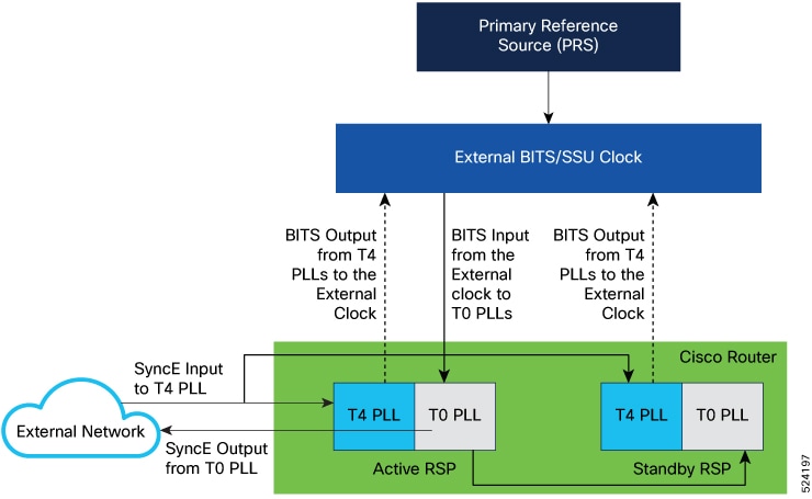
How the Timing Signals Flow when the PRS is Available

This image shows the PRS, external BITS clock, T0 PLL, and T4 PLL timing chips and how the timing signals flow through the timing chips when the PRS is available.

Figure 4. Normal Functioning of the Timing System

These stages describe the flow of the T0 PLL timing signal when the PRS is available:

  1. The external BITS clock receives the PRS signal.

  2. The external BITS clock sends the BITS timing signal to T0 PLL.

  3. The T0 PLL generates a SyncE signal from the BITS signal.

  4. The T0 PLL sends the generated SyncE signal to the external network for synchronization.

These stages describe the flow of the T4 PLL timing signal when the PRS is available. Note that the system keeps itself in a state of readiness to switch over for the potential occurrence of PRS unavailability.

  1. The T4 PLL continuously receives the SyncE signal from the external network.

  2. The T4 PLL generates a BITS signal from the SyncE signal that it receives from the external network.

  3. The T4 PLL sends the generated BITS signal to the external BITS clock for redundancy. The external BITS clock utilizes the redundant signal if the external BITS clock fails. The T4 PLL-generated output is denoted as a dotted arrow because the external BITS clock does not use this timing signal when the PRS is active.

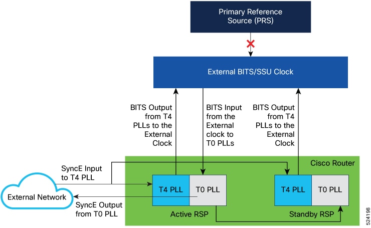
How the Timing Signals Flow when the PRS is Unavailable

This image shows the PRS, external BITS clock, T0 PLL, and T4 PLL timing chips and how the timing signals flow through the timing chips when the PRS is unavailable.

Figure 5. Redundant Functioning of the Timing System

These stages describe the flow of the timing signal when the PRS is unavailable:

  1. The T4 PLL receives the SyncE signal from the external network.

  2. The T4 PLL generates a BITS signal from the SyncE signal.

  3. The external BITS clock switches from its PRS reference to the BITS timing signal sent by the T4 PLL.

  4. The external BITS clock with a high-quality oscillator cleans up the signal and sends it back to the T0 PLL.

  5. The T0 PLL receives the BITS signal and generates a SyncE signal.

  6. The T0 PLL sends the generated SyncE signal to the external network for synchronization.

Configure Network Synchronization Redundancy

The purpose of this task is to configure network synchronization redundancy in a network that uses an external BITS clock. Through these configuration steps, you can achieve redundancy by configuring a single BITS port to receive a network clock input and send a network clock output. The network clock input is the primary timing source and the network clock output is the redundant timing source. The steps cover the configuration of the Active and Standby RSPs. Refer to the Configuring Clocking and Timing chapter for more information on specifying the BITS port as a network clock input or output source.
Before you begin
Procedure

Step 1

Enable the BITS clock source for network synchronization redundancy.

Router(config)#network-clock timing-source bits

Step 2

Enter R0 or R1 for the Active RSP and specify the BITS port as network clock input source in t1 mode.

Router(config)#network-clock input-source 5 External R1 t1 esf linecode b8zs line-build-out 0-133ft

Step 3

Enter R0 or R1 for the Standby RSP and specify the BITS port as network clock input source in t1 mode.

Router(config)#network-clock input-source 10 External R0 t1 esf linecode b8zs line-build-out 0-133ft 

Step 4

Enter R0 or R1 for the Active RSP and specify the BITS port as network clock output source in t1 mode.

Router(config)#network-clock output-source system 20 External R1 t1 esf linecode b8zs line-build-out 0-133ft 

Step 5

Enter R0 or R1 for the Standby RSP and specify the BITS port as network clock output source in t1 mode.

Router(config)#network-clock output-source system 20 External R0 t1 esf linecode b8zs line-build-out 0-133ft

Step 6

Configure the Ethernet interface to receive the SyncE input signal when the PRS is unavailable.


Router(config)#interface GigabitEthernet0/2/0
Router(config)#synchronous mode
Router(config)#network-clock input-source 15 interface GigabitEthernet0/2/0

Configuration Example for Network Synchronization Redundancy

This example shows the configuration for network synchronization redundancy when using a BITS clock.


Router(config)#network-clock synchronization automatic
Router(config)#network-clock synchronization ssm option 2 GEN2 
Router(config)#network-clock synchronization mode QL-enabled
Router(config)#network-clock timing-source bits 
Router(config)#network-clock input-source 15 interface GigabitEthernet0/2/0 
Router(config)#network-clock input-source 5 External R1 t1 esf linecode b8zs line-build-out 0-133ft 
Router(config)#network-clock input-source 10 External R0 t1 esf linecode b8zs line-build-out 0-133ft 
Router(config)#network-clock output-source system 20 External R1 t1 esf linecode b8zs line-build-out 0-133ft 
Router(config)#network-clock output-source system 20 External R0 t1 esf linecode b8zs line-build-out 0-133ft 
Router(config)#network-clock wait-to-restore 50 global
Router(config)#network-clock log ql-change

Verify Network Synchronization Redundancy

You can use these show commands to verify the network synchronization redundancy configuration.

Verify Timing Source
The output shows that the Timing Source Bits has the value Enable to denote that the timing source has been correctly set to BITS.

Router# show network-clocks synchronization global 
Automatic selection process : Enable
Timing Source Bits : Enable
Equipment Clock : 1544 (EEC-Option2)
Clock Mode : QL-Enable
ESMC : Enabled
SSM Option : GEN2 
T0 : External R1 t1 esf 
Hold-off (global) : 300 ms
Wait-to-restore (global) : 50 sec
Tsm Delay : 180 ms
Revertive : No
Verify the Nominated Interfaces

The output shows that the nominated BITS port is used to transmit the timing signal for network synchronization for the Active and Standby RSPs. Verify that R0 and R1 show the configured values.


Router# show network-clocks synchronization
Symbols: En - Enable, Dis - Disable, Adis - Admin Disable
NA - Not Applicable
* - Synchronization source selected
# - Synchronization source force selected
& - Synchronization source manually switched

Automatic selection process : Enable
Timing Source Bits : Enable
Equipment Clock : 1544 (EEC-Option2)
Clock Mode : QL-Enable
ESMC : Enabled
SSM Option : GEN2
T0 : External R1 t1 esf
Hold-off (global) : 300 ms
Wait-to-restore (global) : 50 sec
Tsm Delay : 180 ms
Revertive : No

Nominated Interfaces

 Interface            SigType     Mode/QL  Prio   QL_IN    ESMC Tx  ESMC Rx
 Internal             NA          NA/Dis    251   QL-ST3    NA       NA
 Gi0/2/0              NA          Sync/En    15   QL-PRS    -         -
*External R1      T1 ESF       NA/En       5   QL-PRS    NA       NA
 External R0      T1 ESF       NA/En      10   QL-PRS    NA       NA

T4 Out

External Interface  SigType  Input       Prio Squelch  AIS
External    R1      T1 ESF   T0(Ext R1)   20   FALSE   FALSE
External    R0      T1 ESF   T0(Ext R1)   20   FALSE   FALSE
Verify BITS Input and Output Functionality

The output shows that BITS input and output functionality is supported in this platform. Observe that DPLL2 or T4 PLL and DPLL0 or T0 PLL timing chips are not dependent on a single timing source.

Router# show network-clocks capabilities
Capabilities supported by platform:
NETSYNC_CAP_MODE_QL_EN: QL-Enabled mode 
NETSYNC_CAP_SYNCE: Synchronous Ethernet interfaces
NETSYNC_CAP_EXT: External interfaces
NETSYNC_CAP_EXT_T1: External T1 interfaces
NETSYNC_CAP_EXT_E1: External E1 interfaces
NETSYNC_CAP_EXT_2M: External 2MHz interfaces
NETSYNC_CAP_EXT_10M: External 10MHz interfaces
NETSYNC_CAP_OOR_MON_SUPP: Monitoring all clocks
NETSYNC_CAP_EXT_2048K: Option 1 BITS/SSU ports
NETSYNC_CAP_EXT_IMP_MATCHING: Impedence Matching options on external interfaces
NETSYNC_CAP_PTP_SOURCE: PTP clock as a frequency clock source
NETSYNC_CAP_NETCLK_NOT_INCLUDED: Netclock not included
NETSYNC_CAP_EXT_LINECODE_LBO: Linecode and line-buildout options for external interfaces
NETSYNC_CAP_TIMING_SRC_BITS: Independent timing for DPLL0 and DPLL2
Verify DPLL0 or T0 PLL Lock Status on the Active RSP

The output shows that the DPLL0 or T0 PLL timing chip receives the input signal from the external BITS clock and the lock status is enabled.

Router#show platform hardware slot R1 network-clocks 
Chassis Manager Netclk Status

Primary Reference: REF7 (BITS)
Primary Reference Status: 00

Secondary Reference 0: disabled
Secondary Reference Status: 00
------------<truncated>--------------
DPLL0 Status:
-------------
Bandwidth: 0.100 Hz

Phase Slope Limit: 0.885 usec/sec

Current PLL0 Mode: MANUAL NORMAL

Current Input Selected: REF7 (BITS)

Current PLL0 Holdover Status: OFF

Current PLL0 Lock Status: ON

System CPLD Holdover Status: OFF

System CPLD Lock Status: ON

------------<truncated>--------------
DPLL2 Status:
-------------
Bandwidth: 896 HZ

Phase Slope Limit: unlimited

Current PLL2 Mode: MANUAL NORMAL

Current Input Selected: REF3 (IM)

Current PLL2 Holdover Status: OFF

Current PLL2 Lock Status: ON

Current Input Status:
  REF0 (ACTIVE RSP)      : OK
  REF1 (ACTIVE RSP Sync) : OK
  REF2 (GPS)             : FAIL (SCM, CFM, GST, PFM failed)
  REF3 (IM)              : OK
  REF4 (IM)              : OK
  REF5 (IM)              : FAIL (SCM, CFM, GST, PFM failed)
  REF6 (IM)              : FAIL (SCM, CFM, GST, PFM failed)
  REF7 (BITS)            : OK
  REF8 (Standby BITS)    : OK
  REF9 (SYNC 1PPS)       : FAIL (SCM, CFM, GST, PFM failed)
  REF10 (BITS SYNC)      : FAIL (SCM, CFM, GST, PFM failed)
------------<truncated>--------------
Verify DPLL0 or T0 PLL Lock Status on the Standby RSP

The output shows that the DPLL0 or T0 PLL timing chip lock status is enabled.

Router#show platform hardware slot R0 network-clocks      
Chassis Manager Netclk Status
------------<truncated>--------------
DPLL0 Status:
-------------
Bandwidth: 0.100 Hz

Phase Slope Limit: unlimited

Current PLL0 Mode: MANUAL NORMAL

Current Input Selected: REF7 (BITS)

Current PLL0 Holdover Status: OFF

Current PLL0 Lock Status: ON

System CPLD Holdover Status: OFF

System CPLD Lock Status: ON
------------<truncated>--------------
DPLL2 Status:
-------------
Bandwidth: 896 HZ

Phase Slope Limit: unlimited

Current PLL2 Mode: MANUAL NORMAL

Current Input Selected: REF3 (IM)

Current PLL2 Holdover Status: OFF

Current PLL2 Lock Status: ON

Current Input Status:
  REF0 (ACTIVE RSP)      : OK
  REF1 (ACTIVE RSP Sync) : OK
  REF2 (GPS)             : FAIL (SCM, CFM, GST, PFM failed)
  REF3 (IM)              : OK
  REF4 (IM)              : OK
  REF5 (IM)              : FAIL (SCM, CFM, GST, PFM failed)
  REF6 (IM)              : FAIL (SCM, CFM, GST, PFM failed) 
  REF7 (BITS)            : OK
  REF8 (Standby BITS)    : OK
  REF9 (SYNC 1PPS)       : FAIL (SCM, CFM, GST, PFM failed)
  REF10 (BITS SYNC)      : FAIL (SCM, CFM, GST, PFM failed)

------------<truncated>--------------
  

Disable Network Synchronization Redundancy

The purpose of this task is to disable the network synchronization redundancy. After you disable the functionality, the BITS port can be configured only to receive or send timing signals, and you cannot use the T4 PLL as a redundant timing source. You can now enable the e1 mode. As mentioned in the steps, you can configure either input or output for the active and standby RSPs. Perform the steps when you intend to disable network synchronization redundancy and change to e1 mode:

Procedure

Step 1

Remove the input clock source for the Active RSP.

Router(config)#no network-clock input-source 5 External R1 t1 esf linecode b8zs line-build-out 0-133ft

Step 2

Remove the output clock source for the Standby RSP.

Router(config)#no network-clock input-source 10 External R0 t1 esf linecode b8zs line-build-out 0-133ft 

Step 3

Remove the output clock source for the Active RSP.

Router(config)#no network-clock output-source system 20 External R1 t1 esf linecode b8zs line-build-out 0-133ft 

Step 4

Remove the output clock source for the Standby RSP.

Router(config)#no network-clock output-source system 20 External R0 t1 esf linecode b8zs line-build-out 0-133ft

Step 5

Disable network synchronization redundancy by removing the external BITS clock configuration.

Router(config)#no network-clock timing-source bits

Step 6

Remove the SSM Option 2.

Router(config)#no network-clock synchronization ssm option 2 GEN2

Step 7

Execute the commands to configure the BITS port as the network clock input or output source in the e1 mode. Enter R0 or R1 for the Active RSP.

Input source:

Router(config)#network-clock input-source 1 External R0 e1 crc4 120ohms linecode ami

Output source:


Router(config)#network-clock output-source system 1 External R0 e1 crc4 120ohms linecode ami

Step 8

Execute the commands to configure the BITS port as the network clock input or output source in the e1 mode. Enter R0 or R1 for the Standby RSP.

Input source:

Router(config)#network-clock input-source 1 External R1 e1 crc4 120ohms linecode ami

Output source:

Router(config)#network-clock output-source system 1 External R1 e1 crc4 120ohms linecode ami

Understanding Synchronous Ethernet ESMC and SSM

Synchronous Ethernet incorporates the Synchronization Status Message (SSM) used in Synchronous Optical Networking (SONET) and Synchronous Digital Hierarchy (SDH) networks. While SONET and SDH transmit the SSM in a fixed location within the frame, Ethernet Synchronization Message Channel (ESMC) transmits the SSM using a protocol: the IEEE 802.3 Organization-Specific Slow Protocol (OSSP) standard.

The ESMC carries a Quality Level (QL) value identifying the clock quality of a given synchronous Ethernet timing source. Clock quality values help a synchronous Ethernet node derive timing from the most reliable source and prevent timing loops.

When configured to use synchronous Ethernet, the chassis synchronizes to the best available clock source. If no better clock sources are available, the chassis remains synchronized to the current clock source.

The chassis supports two clock selection modes: QL-enabled and QL-disabled. Each mode uses different criteria to select the best available clock source.

For more information about Ethernet ESMC and SSM, see Configuring Synchronous Ethernet ESMC and SSM.


Note


The chassis can only operate in one clock selection mode at a time.

Note


PTP clock sources are not supported with synchronous Ethernet.

Clock Selection Modes

The chassis supports two clock selection modes, which are described in the following sections.

QL-Enabled Mode

In QL-enabled mode, the chassis considers the following parameters when selecting a clock source:

  • Clock quality level (QL)
  • Clock availability
  • Priority
QL-Disabled Mode

In QL-disabled mode, the chassis considers the following parameters when selecting a clock source:

  • Clock availability
  • Priority

Note


You can use override the default clock selection using the commands described in the Managing Clock Source Selection.

Note


8275.1 profile does not support QL-disabled mode on RSP3.


Managing Clock Selection

You can manage clock selection by changing the priority of the clock sources; you can also influence clock selection by modifying modify the following clock properties:

  • Hold-Off Time: If a clock source goes down, the chassis waits for a specific hold-off time before removing the clock source from the clock selection process. By default, the value of hold-off time is 300 ms.
  • Wait to Restore: The amount of time that the chassis waits before including a newly active synchronous Ethernet clock source in clock selection. The default value is 300 seconds.
  • Force Switch: Forces a switch to a clock source regardless of clock availability or quality.
  • Manual Switch: Manually selects a clock source, provided the clock source has a equal or higher quality level than the current source.

For more information about how to use these features, see Managing Clock Source Selection.

Configuring Clocking and Timing

The following sections describe how to configure clocking and timing features on the chassis:

Configuring an Ordinary Clock

The following sections describe how to configure the chassis as an ordinary clock.

Configuring a Server Ordinary Clock

Follow these steps to configure the chassis to act as a Server ordinary clock.

Procedure

Step 1

enable

Example:

Router> enable

Enables privileged EXEC mode.

  • Enter your password if prompted.

Step 2

configure terminal

Example:

Router# configure terminal

Enters configuration mode.

Step 3

platformptp masterprtc-only-enable

Example:
Router(config)# platform ptp master prtc-only-enable

(Optional) Enable port deletion of the server clock.

Step 4

ptp clock {ordinary | boundary | e2e-transparent } domain domain-number

Example:

Router(config)# ptp clock ordinary domain 0
Example:

Router(config-ptp-clk)#

Configures the PTP clock. You can create the following clock types:

  • ordinary—A 1588 clock with a single PTP port that can operate in Server or Client mode.

  • boundary—Terminates PTP session from Grandmaster and acts as PTP Server or Client clocks downstream.

  • e2e-transparent—Updates the PTP time correction field to account for the delay in forwarding the traffic. This helps improve the accuracy of 1588 clock at client.

Step 5

priority1 priorityvalue

Example:

Router(config-ptp-clk)# priority1 priorityvalue 

Sets the preference level for a clock. client devices use the priority1 value when selecting a server clock: a lower priority1 value indicates a preferred clock. The priority1 value is considered above all other clock attributes.

Valid values are from 0-255. The default value is 128.

Step 6

priority2 priorityvalue

Example:

Router(config-ptp-clk)# priority2 priorityvalue 

Sets a secondary preference level for a clock. client devices use the priority2 value when selecting a server clock: a lower priority2 value indicates a preferred clock. The priority2 value is considered only when the chassis is unable to use priority1 and other clock attributes to select a clock.

Valid values are from 0-255. The default value is 128.

Step 7

utc-offset value leap-second “date time” offset { -1 | 1}

Example:
Router(config-ptp-clk)# utc-offset 45 leap-second “01-01-2017 00:00:00” offset 1

(Optional) Starting with Cisco IOS-XE Release 3.18SP, the new utc-offset CLI is used to set the UTC offset value.

Valid values are from 0-255. The default value is 36.

(Optional) Starting with Cisco IOS-XE Release 3.18.1SP, you can configure the current UTC offset, leap second event date and Offset value (+1 or -1). Leap second configuration will work only when the frequency source is locked and ToD was up before.

  • “date time”—Leap second effective date in dd-mm-yyyy hh:mm:ss format.

Step 8

input [1pps] {R0 | R1}

Example:

Router(config-ptp-clk)# input 1pps R0

Enables Precision Time Protocol input 1PPS using a 1PPS input port.

Use R0 or R1 to specify the active RSP slot.

Step 9

tod {R0 | R1} {ubx | nmea | cisco | ntp | cmcc }

Example:

Router(config-ptp-clk)# tod R0 ntp

Configures the time of day message format used by the ToD interface.

Note


It is mandatory that when electrical ToD is used, the utc-offset command is configured before configuring the tod R0, otherwise there will be a time difference of approximately 37 seconds between the server and client clocks.

Note

 
The ToD port acts as an input port in case of server clock and as an output port in case of client clock.

Step 10

clock-port port-name {master | slave } [profile {g8265.1 }]

Example:

Router(config-ptp-clk)# clock-port server-port master 

Defines a new clock port and sets the port to PTP Server or Client mode; in server mode, the port exchanges timing packets with PTP client devices.

The profile keyword configures the clock to use the G.8265.1 recommendations for establishing PTP sessions, determining the best server clock, handling SSM, and mapping PTP classes.

Note

 
Using a telecom profile requires that the clock have a domain number of 4–23.

Step 11

Do one of the following:

  • transport ipv4 unicast interface interface-type interface-number [ negotiation ]
  • transport ethernet unicast [negotiation ]
Example:

Router(config-ptp-port)# transport ipv4 unicast interface loopback 0 negotiation

Specifies the transport mechanism for clocking traffic; you can use IPv4 or Ethernet transport.

The negotiation keyword configures the chassis to discover a PTP server clock from all available PTP clock sources.

Note

 
PTP redundancy is supported only on unicast negotiation mode.

Step 12

exit

Exits clock-port configuration.

Step 13

network-clock synchronization automatic

Example:

Router(config)# network-clock synchronization automatic

Enables automatic selection of a clock source.

Note


This command must be configured before any input source.

Step 14

network-clock synchronization mode ql-enabled

Example:

Router(config)# network-clock synchronization mode ql-enabled

Enables automatic selection of a clock source based on quality level (QL).

Note

 
This command is disabled by default.

Step 15

Use one of the following options:

  • network-clock input-source priority controller {SONET | wanphy}
  • network-clock input-source priority external {R0 | R1} [10m | 2m]
  • network-clock input-source priority external {R0 | R1} [2048k | e1 {cas {120ohms | 75ohms | crc4}}]
  • network-clock input-source priority external {R0 | R1} [2048k | e1 {crc4 | fas] {120ohms | 75ohms} {linecode {ami | hdb3}}
  • network-clock input-source priority external {R0 | R1} [t1 {d4 | esf | sf} {linecode {ami | b8zs}}]
  • network-clock input-source priority interface type/slot/port
Example:

Router(config)# network-clock input-source 1 external R0 10m
  • (Optional) To nominate SDH or SONET controller as network clock input source.

  • (Optional) To nominate 10Mhz port as network clock input source.

  • (Optional) To nominate BITS port as network clock input source in e1 mode.

  • (Optional) To nominate BITS port as network clock input source in e1 mode.

  • (Optional) To nominate BITS port as network clock input source in t1 mode.

  • (Optional) To nominate Ethernet interface as network clock input source.

Step 16

clock destination source-address | mac-address {bridge-domain bridge-domain-id} | interface interface-name }

Example:

Router(config-ptp-port)# clock-source 10.8.8.1 

Specifies the IP address or MAC address of a clock destination when the chassis is in PTP server mode.

Step 17

sync interval interval

Example:

Router(config-ptp-port)# sync interval -4

Specifies the interval used to send PTP synchronization messages. The intervals are set using log base 2 values, as follows:

  • 1—1 packet every 2 seconds

  • 0—1 packet every second

  • -1—1 packet every 1/2 second, or 2 packets per second

  • -2—1 packet every 1/4 second, or 4 packets per second

  • -3—1 packet every 1/8 second, or 8 packets per second

  • -4—1 packet every 1/16 seconds, or 16 packets per second.

  • -5—1 packet every 1/32 seconds, or 32 packets per second.

  • -6—1 packet every 1/64 seconds, or 64 packets per second.

  • -7—1 packet every 1/128 seconds, or 128 packets per second.

Step 18

announce interval interval

Example:

Router(config-ptp-port)# announce interval 2

Specifies the interval for PTP announce messages. The intervals are set using log base 2 values, as follows:

  • 3—1 packet every 8 seconds

  • 2—1 packet every 4 seconds

  • 1—1 packet every 2 seconds

  • 0—1 packet every second

  • -1—1 packet every 1/2 second, or 2 packets per second

  • -2—1 packet every 1/4 second, or 4 packets per second

  • -3—1 packet every 1/8 second, or 8 packets per second

Step 19

end

Example:

Router(config-ptp-port)# end

Exit configuration mode.

Step 20

linecode {ami | b8zs | hdb3}

Example:
 Router(config-controller)# linecode ami

Selects the linecode type.

  • ami—Specifies Alternate Mark Inversion (AMI) as the linecode type. Valid for T1 and E1 controllers.

  • b8zs—Specifies binary 8-zero substitution (B8ZS) as the linecode type. Valid for sonet controller only. This is the default for T1 lines.

  • hdb3—Specifies high-density binary 3 (hdb3) as the linecode type. Valid for E1 controller only. This is the default for E1 lines.


Example
The following example shows that the utc-offset is configured before configuring the ToD to avoid a delay of 37 seconds between the Server or Client clocks:
ptp clock ordinary domain 24

local-priority 1

priority2 128
utc-offset 37
tod R0 cisco
clock-port server-port-1 master profile g8275.1 local-priority 1
transport ethernet multicast interface Gig 0/0/1

Configuring a Client Ordinary Clock

Follow these steps to configure the chassis to act as a client ordinary clock.

Procedure

Step 1

enable

Example:

Router> enable

Enables privileged EXEC mode.

  • Enter your password if prompted.

Step 2

configure terminal

Example:

Router# configure terminal

Enter configuration mode.

Step 3

ptp clock {ordinary | boundary | e2e-transparent } domain domain-number [hybrid ]

Example:

Router(config)# ptp clock ordinary domain 0

Configures the PTP clock. You can create the following clock types:

  • ordinary—A 1588 clock with a single PTP port that can operate in Server or Client mode.

  • boundary—Terminates PTP session from Grandmaster and acts as PTP Server to Client downstream.

  • e2e-ransparent—Updates the PTP time correction field to account for the delay in forwarding the traffic. This helps improve the acuracy of 1588 clock at client.

Step 4

output [1pps] {R0 | R1} [offset offset-value] [pulse-width value]

Example:

Router(config-ptp-clk)# output 1pps R0 offset 200 pulse-width 20 μsec

Enables Precision Time Protocol input 1PPS using a 1PPS input port.

Use R0 or R1 to specify the active RSP slot.

Note


Effective Cisco IOS XE Everest 16.6.1, the 1pps pulse bandwith can be changed from the default value of 500 milliseconds to up to 20 microseconds.

Step 5

tod {R0 | R1} {ubx | nmea | cisco | ntp | cmcc }

Example:

Router(config-ptp-clk)# tod R0 ntp

Configures the time of day message format used by the ToD interface.

Note

 
The ToD port acts as an input port in case of server clock and as an output port in case of client clock.

Step 6

clock-port port-name {master | slave } [profile {g8265.1 }]

Example:

Router(config-ptp-clk)# clock-port client-port slave

Sets the clock port to PTP Server or Client mode; in client mode, the port exchanges timing packets with a PTP server clock.

The profile keyword configures the clock to use the G.8265.1 recommendations for establishing PTP sessions, determining the best server clock, handling SSM, and mapping PTP classes.

Note

 
Using a telecom profile requires that the clock have a domain number of 4–23.

Step 7

Do one of the following:

  • transport ipv4 unicast interface interface-type interface-number [ negotiation ]
  • transport ethernet unicast [negotiation ]
Example:

Router(config-ptp-port)# transport ipv4 unicast interface loopback 0 negotiation

Specifies the transport mechanism for clocking traffic; you can use IPv4 or Ethernet transport.

The negotiation keyword configures the chassis to discover a PTP server clock from all available PTP clock sources.

Note

 
PTP redundancy is supported only on unicast negotiation mode.

Step 8

clock source source-address | mac-address {bridge-domain bridge-domain-id } | interface interface-name } [priority ] [delay-asymmetry delay asymmetry value nanoseconds]

Example:

Router(config-ptp-port)# clock-source 10.8.8.1

Specifies the IP or MAC address of a PTP server clock.

  • priority —Sets the preference level for a PTP clock.

  • delay asymmetry value —Performs the PTP asymmetry readjustment on a PTP node to compensate for the delay in the network.

Step 9

announce timeout value

Example:

Router(config-ptp-port)# announce timeout 8

Specifies the number of PTP announcement intervals before the session times out. Valid values are 1-10.

Step 10

delay-req interval interval

Example:

Router(config-ptp-port)# delay-req interval 1

Configures the minimum interval allowed between PTP delay-request messages when the port is in the server state.

The intervals are set using log base 2 values, as follows:

  • 3—1 packet every 8 seconds

  • 2—1 packet every 4 seconds

  • 1—1 packet every 2 seconds

  • 0—1 packet every second

  • -1—1 packet every 1/2 second, or 2 packets per second

  • -2—1 packet every 1/4 second, or 4 packets per second

  • -3—1 packet every 1/8 second, or 8 packets per second

  • -4—1 packet every 1/16 seconds, or 16 packets per second.

  • -5—1 packet every 1/32 seconds, or 32 packets per second.

  • -6—1 packet every 1/64 seconds, or 64 packets per second.

  • -7—1 packet every 1/128 seconds, or 128 packets per second.

Step 11

end

Example:

Router(config-ptp-port)# end

Exit configuration mode.

Step 12

Router(config-controller)# linecode {ami | b8zs | hdb3}

Selects the linecode type.

  • ami—Specifies Alternate Mark Inversion (AMI) as the linecode type. Valid for T1 and E1 controllers.

  • b8zs—Specifies binary 8-zero substitution (B8ZS) as the linecode type. Valid for sonet controller only. This is the default for T1 lines.

  • hdb3—Specifies high-density binary 3 (hdb3) as the linecode type. Valid for E1 controller only. This is the default for E1 lines.


Configuring a Boundary Clock

Follow these steps to configure the chassis to act as a boundary clock.

Procedure


Step 1

enable

Example:


Router> enable

Enables privileged EXEC mode.

  • Enter your password if prompted.

Step 2

configure terminal

Example:


Router# configure terminal

Enter configuration mode.

Step 3

Router(config)# ptp clock {ordinary | boundary | e2e-transparent } domain domain-number [hybrid ]

Example:


Router(config)# ptp clock boundary domain 0

Configures the PTP clock. You can create the following clock types:

  • ordinary—A 1588 clock with a single PTP port that can operate in Server or Client mode.

  • boundary—Terminates PTP session from Grandmaster and acts as PTP server to client clocks downstream.

  • e2e-ransparent—Updates the PTP time correction field to account for the delay in forwarding the traffic. This helps improve the acuracy of 1588 clock at client.

Step 4

time-properties persist value

Example:

Router(config-ptp-clk)#
time-properties persist 600

(Optional) Starting with Cisco IOS-XE Release 3.18.1SP, you can configure time properties holdover time. Valid values are from 0 to 10000 seconds. The default value is 300 seconds.

When a server clock is lost, the time properties holdover timer starts. During this period, the time properties flags (currentUtcOffset, currentUtcOffsetValid, leap61, leap59) persist for the holdover timeout period. Once the holdover timer expires, currentUtcOffsetValid, leap59, and leap61 flags are set to false and the currentUtcOffset remains unchanged. In case leap second midnight occurs when holdover timer is running, utc-offset value is updated based on leap59 or leap61 flags. This value is used as long as there are no PTP packets being received from the selected server clock. In case the selected server clock is sending announce packets, the time-properties advertised by server clock is used.

Step 5

clock-port port-name {master | slave } [profile {g8265.1 }]

Example:


Router(config-ptp-clk)# clock-port client-port slave

Sets the clock port to PTP Server or Client mode; in client mode, the port exchanges timing packets with a PTP server clock.

The profile keyword configures the clock to use the G.8265.1 recommendations for establishing PTP sessions, determining the best server clock, handling SSM, and mapping PTP classes.

Note

 
Using a telecom profile requires that the clock have a domain number of 4–23.

Step 6

transport ipv4 unicast interface interface-type interface-number [ negotiation ]

Example:


Router(config-ptp-port)# transport ipv4 unicast interface Loopback 0 negotiation

Specifies the transport mechanism for clocking traffic.

The negotiation keyword configures the chassis to discover a PTP server clock from all available PTP clock sources.

Note

 
PTP redundancy is supported only on unicast negotiation mode.

Step 7

clock-source source-address [priority]

Example:


Router(config-ptp-port)# clock source 192.168.0.2

Specifies the address of a PTP server clock. You can specify a priority value as follows:

  • No priority value—Assigns a priority value of 0.

  • 1—Assigns a priority value of 1.

  • 2—Assigns a priority value of 2, the highest priority.

Step 8

clock-port port-name {master | slave } [profile {g8265.1 }]

Example:


Router(config-ptp-port)# clock-port server-port master

Sets the clock port to PTP Server or Client mode; in server mode, the port exchanges timing packets with PTP client devices.

Note

 
The server clock-port does not establish a clocking session until the client clock-port is phase aligned.

The profile keyword configures the clock to use the G.8265.1 recommendations for establishing PTP sessions, determining the best server clock, handling SSM, and mapping PTP classes.

Note

 
Using a telecom profile requires that the clock have a domain number of 4–23.

Step 9

transport ipv4 unicast interface interface-type interface-number [ negotiation ]

Example:


Router(config-ptp-port)# transport ipv4 unicast interface Loopback 1 negotiation

Specifies the transport mechanism for clocking traffic.

The negotiation keyword configures the chassis to discover a PTP server clock from all available PTP clock sources.

Note

 
PTP redundancy is supported only on unicast negotiation mode.

Step 10

end

Example:


Router(config-ptp-port)# end

Exit configuration mode.

Step 11

Router(config-controller)# linecode {ami | b8zs | hdb3}

Selects the linecode type.

  • ami—Specifies Alternate Mark Inversion (AMI) as the linecode type. Valid for T1 and E1 controllers.

  • b8zs—Specifies binary 8-zero substitution (B8ZS) as the linecode type. Valid for sonet controller only. This is the default for T1 lines.

  • hdb3—Specifies high-density binary 3 (hdb3) as the linecode type. Valid for E1 controller only. This is the default for E1 lines.


What to do next

Configuring a Transparent Clock

Follow these steps to configure the chassis as an end-to-end transparent clock.


Note


The Cisco NCS 4206 Series Chassis does not support peer-to-peer transparent clock mode.

Note


The transparent clock ignores the domain number.

Procedure


Step 1

enable

Example:


Router> enable

Enables privileged EXEC mode.

  • Enter your password if prompted.

Step 2

configure terminal

Example:


Router# configure terminal

Enter configuration mode.

Step 3

ptp clock {ordinary | boundary | e2e-transparent } domain domain-number [hybrid ]

Example:

Router(config)# ptp clock e2e-transparent domain  4 

Configures the chassis as an end-to-end transparent clock.

Step 4

exit

Example:


Router(config)# exit

Exit configuration mode.

Step 5

Router(config-controller)# linecode {ami | b8zs | hdb3}

Selects the linecode type.

  • ami—Specifies Alternate Mark Inversion (AMI) as the linecode type. Valid for T1 and E1 controllers.
  • b8zs—Specifies binary 8-zero substitution (B8ZS) as the linecode type. Valid for sonet controller only. This is the default for T1 lines.
  • hdb3—Specifies high-density binary 3 (hdb3) as the linecode type. Valid for E1 controller only. This is the default for E1 lines.

Configuring a Hybrid Clock

The following sections describe how to configure the chassis to act as a hybrid clock.

Configuring a Hybrid Boundary Clock

Follow these steps to configure a hybrid clocking in boundary clock mode.


Note


When configuring a hybrid clock, ensure that the frequency and phase sources are traceable to the same server clock.
Procedure

Step 1

enable

Example:

Router> enable

Enables privileged EXEC mode.

  • Enter your password if prompted.

Step 2

configure terminal

Example:

Router# configure terminal

Enter configuration mode.

Step 3

ptp clock {boundary } domain domain-number [hybrid ]

Example:

Router(config)# ptp clock boundary domain 0 hybrid

Configures the PTP clock. You can create the following clock types:

Note

 
Hybrid mode is only supported with client clock-ports; server mode is not supported.
  • boundary—Terminates PTP session from Grandmaster and acts as PTP Server to Client downstream.

Step 4

time-properties persist value

Example:
Router(config-ptp-clk)# time-properties persist 600

(Optional) Starting with Cisco IOS-XE Release 3.18.1SP, you can configure time properties holdover time. Valid values are from 0 to 10000 seconds. The default value is 300 seconds.

When a server clock is lost, the time properties holdover timer starts. During this period, the time properties flags (currentUtcOffset, currentUtcOffsetValid, leap61, leap59) persist for the holdover timeout period. Once the holdover timer expires, currentUtcOffsetValid, leap59, and leap61 flags are set to false and the currentUtcOffset remains unchanged. In case leap second midnight occurs when holdover timer is running, utc-offset value is updated based on leap59 or leap61 flags. This value is used as long as there are no PTP packets being received from the selected server clock. In case the selected server clock is sending announce packets, the time-properties advertised by server is used.

Step 5

utc-offset value leap-second "date time" offset { -1 | 1}

Example:
Router(config-ptp-clk)# utc-offset 45 leap-second "01-01-2017 00:00:00" offset 1

(Optional) Starting with Cisco IOS XE Release 3.18SP, the new utc-offset CLI is used to set the UTC offset value.

Valid values are from 0-255. The default value is 36.

(Optional) Starting with Cisco IOS-XE Release 3.18.1SP, you can configure the current UTC offset, leap second event date and Offset value (+1 or -1). Leap second configuration will work only when the frequency source is locked and ToD was up before.

  • "date time"—Leap second effective date in dd-mm-yyyy hh:mm:ss format.

Step 6

min-clock-class value

Example:

Router(config-ptp-clk)# min-clock-class 157

Sets the threshold clock-class value. This allows the PTP algorithm to use the time stamps from a upstream server clock, only if the clock-class sent by the server clock is less than or equal to the configured threshold clock-class.

Valid values are from 0-255.

Note


Min-clock-class value is supported only for PTP with single server clock source configuration.

Step 7

clock-port port-name {master | slave } [profile {g8265.1 }]

Example:

Router(config-ptp-clk)# clock-port client-port slave

Sets the clock port to PTP server or client mode; in client mode, the port exchanges timing packets with a PTP server clock.

Note

 
Hybrid mode is only supported with client clock-ports; server mode is not supported.

The profile keyword configures the clock to use the G.8265.1 recommendations for establishing PTP sessions, determining the best server clock, handling SSM, and mapping PTP classes.

Note

 
Using a telecom profile requires that the clock have a domain number of 4–23.

Step 8

transport ipv4 unicast interface interface-type interface-number [ negotiation single-hop]

Example:

Router(config-ptp-port)# transport ipv4 unicast interface Loopback 0 negotiation
or
Router(config-ptp-port)# transport ipv4 unicast interface Loopback 0 negotiation single-hop

Specifies the transport mechanism for clocking traffic.

negotiation —(Optional) configures the chassis to discover a PTP server clock from all available PTP clock sources.

Note

 
PTP redundancy is supported only on unicast negotiation mode.

single-hop —(Optional)Must be configured, if Hop-by-Hop PTP ring topology is used. It ensures that the PTP node communicates only with the adjacent nodes.

Step 9

clock-source source-address [priority]

Example:

Router(config-ptp-port)# clock source 192.168.0.2

Specifies the address of a PTP server clock. You can specify a priority value as follows:

  • No priority value—Assigns a priority value of 0.

  • 1—Assigns a priority value of 1.

  • 2—Assigns a priority value of 2, the highest priority.

Step 10

clock-port port-name {master | slave } [profile {g8265.1 }]

Example:

Router(config-ptp-port)# clock-port server-port master

Sets the clock port to PTP server or client mode; in server mode, the port exchanges timing packets with PTP client devices.

The profile keyword configures the clock to use the G.8265.1 recommendations for establishing PTP sessions, determining the best server clock, handling SSM, and mapping PTP classes.

Note

 
Using a telecom profile requires that the clock have a domain number of 4–23.

Step 11

transport ipv4 unicast interface interface-type interface-number [ negotiation ] [ single-hop]

Example:

Router(config-ptp-port)# transport ipv4 unicast interface Lo1 negotiation
or
Router(config-ptp-port)# transport ipv4 unicast interface Lo1 negotiation single-hop

Specifies the transport mechanism for clocking traffic.

negotiation —(Optional)configures the chassis to discover a PTP server clock from all available PTP clock sources.

Note

 
PTP redundancy is supported only on unicast negotiation mode.

single-hop —(Optional) Must be configured, if Hop-by-Hop PTP ring topology is used. It ensures that the PTP node communicates only with the adjacent nodes.

Step 12

exit

Exit clock-port configuration.

Step 13

network-clock synchronization automatic

Example:

Router(config)# network-clock synchronization automatic

Enables automatic selection of a clock source.

Note


This command must be configured before any input source.

Step 14

network-clock synchronization mode ql-enabled

Example:

Router(config)# network-clock synchronization mode ql-enabled

Enables automatic selection of a clock source based on quality level (QL).

Note

 
This command is disabled by default.

Step 15

Use one of the following options:

  • network-clock input-source priority controller {SONET | wanphy}
  • network-clock input-source priority external {R0 | R1} [10m | 2m]
  • network-clock input-source priority external {R0 | R1} [2048k | e1 {cas {120ohms | 75ohms | crc4}}]
  • network-clock input-source priority external {R0 | R1} [2048k | e1 {crc4 | fas] {120ohms | 75ohms} {linecode {ami | hdb3}}
  • network-clock input-source priority external {R0 | R1} [t1 {d4 | esf | sf} {linecode {ami | b8zs}}]
  • network-clock input-source priority interface type/slot/port
Example:

Router(config)# network-clock input-source 1 external R0 10m
  • (Optional) To nominate SDH or SONET controller as network clock input source.

  • (Optional) To nominate 10Mhz port as network clock input source.

  • (Optional) To nominate BITS port as network clock input source in e1 mode.

  • (Optional) To nominate BITS port as network clock input source in e1 mode.

  • (Optional) To nominate BITS port as network clock input source in t1 mode.

  • (Optional) To nominate Ethernet interface as network clock input source.

Step 16

network-clock synchronization input-threshold ql value

Example:
Router(config)# network-clock synchronization input-threshold <ql value> 

(Optional) Starting with Cisco IOS-XE Release 3.18SP, this new CLI is used to set the threshold QL value for the input frequency source. The input frequency source, which is better than or equal to the configured threshold QL value, will be selected to recover the frequency. Otherwise, internal clock is selected.

Step 17

network-clock hold-off {0 | milliseconds }

Example:

Router(config)# network-clock hold-off 0

(Optional) Configures a global hold-off timer specifying the amount of time that the chassis waits when a synchronous Ethernet clock source fails before taking action.

Note

 
You can also specify a hold-off value for an individual interface using the network-clock hold-off command in interface mode.

For more information about this command, see Configuring Clocking and Timing

Step 18

platformptpmasteralways-on

Example:
Router(config)# platform ptp master always-on

(Optional) Keeps the server port up all the time. So, when the frequency source has acceptable QL, the egress packets are sent to the downstream clients even when the server port is not phase aligned.

Step 19

platformptphybrid-bcdownstream-enable

Example:
Router(config)# platform ptp hybrid-bc downstream-enable

(Optional) Enables bust mode. When the difference between the forward timestamp of the previous packet and current packet is greater than 100ns, such timestamps are not provided to the APR. Due to this setting, the APR does not see unexpected and random time jumps in two sequential timestamps of the same PTP message-types. The same applies for the reverse path timestamps as well.

Step 20

end

Example:

Router(config)# end

Exit configuration mode.

Step 21

Router(config-controller)# linecode {ami | b8zs | hdb3}

Selects the linecode type.

  • ami—Specifies Alternate Mark Inversion (AMI) as the linecode type. Valid for T1 and E1 controllers.

  • b8zs—Specifies binary 8-zero substitution (B8ZS) as the linecode type. Valid for sonet controller only. This is the default for T1 lines.

  • hdb3—Specifies high-density binary 3 (hdb3) as the linecode type. Valid for E1 controller only. This is the default for E1 lines.


Configuring a Hybrid Ordinary Clock

Follow these steps to configure a hybrid clocking in ordinary clock client mode.


Note


When configuring a hybrid clock, ensure that the frequency and phase sources are traceable to the same server clock.


Procedure

Step 1

enable

Example:

Router> enable

Enables privileged EXEC mode.

  • Enter your password if prompted.

Step 2

configure terminal

Example:

Router# configure terminal

Enter configuration mode.

Step 3

ptp clock {ordinary | boundary | e2e-transparent } domain domain-number [hybrid ]

Example:

Router(config)# ptp clock ordinary domain 0 hybrid

Configures the PTP clock. You can create the following clock types:

  • ordinary—A 1588 clock with a single PTP port that can operate in Server or Client mode.

    Note


    Hybrid mode is only supported with client clock-ports; server mode is not supported.

  • boundary—Terminates PTP session from Grandmaster and acts as PTP Server to Client downstream.

  • e2e-ransparent—Updates the PTP time correction field to account for the delay in forwarding the traffic. This helps improve the acuracy of 1588 clock at client.

Step 4

output [1pps] {R0 | R1} [offset offset-value] [pulse-width value]

Example:

Router(config-ptp-clk)# output 1pps R0 offset 200 pulse-width 20 μsec

Enables Precision Time Protocol input 1PPS using a 1PPS input port.

Use R0 or R1 to specify the active RSP slot.

Note


Effective Cisco IOS XE Everest 16.6.1, the 1pps pulse bandwith can be changed from the default value of 500 milliseconds to up to 20 microseconds.

Step 5

tod {R0 | R1} {ubx | nmea | cisco | ntp | cmcc }

Example:

Router(config-ptp-clk)# tod R0 ntp

Configures the time of day message format used by the ToD interface.

Note


The ToD port acts as an input port in case of server clock and as an output port in case of client clock.

Step 6

clock-port port-name {master | slave } [profile {g8265.1 }]

Example:

Router(config-ptp-clk)# clock-port client-port slave

Sets the clock port to PTP Server or Client mode; in client mode, the port exchanges timing packets with a PTP server clock.

Note


Hybrid mode is only supported with client clock-ports; server mode is not supported.

The profile keyword configures the clock to use the G.8265.1 recommendations for establishing PTP sessions, determining the best server clock, handling SSM, and mapping PTP classes.

Note


Using a telecom profile requires that the clock have a domain number of 4–23.

Step 7

transport ipv4 unicast interface interface-type interface-number [ negotiation ]

Example:

Router(config-ptp-port)# transport ipv4 unicast interface Loopback 0 negotiation

Specifies the transport mechanism for clocking traffic.

The negotiation keyword configures the router to discover a PTP server clock from all available PTP clock sources.

Note


PTP redundancy is supported only on unicast negotiation mode.

Step 8

clock-source source-address [priority]

Example:

Router(config-ptp-port)# clock source 192.168.0.2

Specifies the address of a PTP server clock. You can specify a priority value as follows:

  • No priority value—Assigns a priority value of 0.

  • 1—Assigns a priority value of 1.

  • 2—Assigns a priority value of 2, the highest priority.

Step 9

exit

Example:

Router(config-ptp-port)# exit

Exit clock-port configuration.

Step 10

network-clock synchronization automatic

Example:

Router(config-ptp-clk)# network-clock synchronization automatic

Enables automatic selection of a clock source.

Note


This command must be configured before any input source.

Step 11

network-clock synchronization mode ql-enabled

Example:

Router(config-ptp-clk)# network-clock synchronization mode ql-enabled

Enables automatic selection of a clock source based on quality level (QL).

Note


This command is disabled by default.

For more information about this command, see Configuring Clocking and Timing

Step 12

Use one of the following options:

  • network-clock input-source <priority> controller {SONET | wanphy}
  • network-clock input-source <priority> external {R0 | R1} [10m | 2m]
  • network-clock input-source <priority> external {R0 | R1} [2048k | e1 {cas {120ohms | 75ohms | crc4}}]
  • network-clock input-source <priority> external {R0 | R1} [2048k | e1 {crc4 | fas] {120ohms | 75ohms} {linecode {ami | hdb3}}
  • network-clock input-source <priority> external {R0 | R1} [t1 {d4 | esf | sf} {linecode {ami | b8zs}}]
  • network-clock input-source <priority> interface <type/slot/port>
Example:

Router(config)# network-clock input-source 1 external R0 10m
  • (Optional) To nominate SDH or SONET controller as network clock input source.

  • (Optional) To nominate 10Mhz port as network clock input source.

  • (Optional) To nominate BITS port as network clock input source in e1 mode.

  • (Optional) To nominate BITS port as network clock input source in e1 mode.

  • (Optional) To nominate BITS port as network clock input source in t1 mode.

  • (Optional) To nominate Ethernet interface as network clock input source.

Step 13

network-clock hold-off {0 | milliseconds }

Example:

Router(config-ptp-clk)# network-clock hold-off 0

(Optional) Configures a global hold-off timer specifying the amount of time that the router waits when a synchronous Ethernet clock source fails before taking action.

Note


You can also specify a hold-off value for an individual interface using the network-clock hold-off command in interface mode.

For more information about this command, see Configuring Clocking and Timing

Step 14

end

Example:

Router(config-ptp-clk)# end

Exit configuration mode.

Step 15

Router(config-controller)# linecode {ami | b8zs | hdb3}

Selects the linecode type.

  • ami—Specifies Alternate Mark Inversion (AMI) as the linecode type. Valid for T1 and E1 controllers.

  • b8zs—Specifies binary 8-zero substitution (B8ZS) as the linecode type. Valid for sonet controller only. This is the default for T1 lines.

  • hdb3—Specifies high-density binary 3 (hdb3) as the linecode type. Valid for E1 controller only. This is the default for E1 lines.


Configuring PTP Redundancy

The following sections describe how to configure PTP redundancy on the chassis:

Configuring PTP Redundancy in Client Clock Mode

Follow these steps to configure clocking redundancy in client clock mode:

Procedure

Step 1

enable

Example:

Router> enable

Enables privileged EXEC mode.

  • Enter your password if prompted.

Step 2

configure terminal

Example:

Router# configure terminal

Enter configuration mode.

Step 3

ptp clock {ordinary | boundary | e2e-transparent } domain domain-number [hybrid ]

Example:

Router(config#) ptp clock ordinary domain 0

Configures the PTP clock. You can create the following clock types:

  • ordinary—A 1588 clock with a single PTP port that can operate in Server or Client mode.

  • boundary—Terminates PTP session from Grandmaster and acts as PTP Server to Client clocks downstream.

  • e2e-ransparent—Updates the PTP time correction field to account for the delay in forwarding the traffic. This helps improve the acuracy of 1588 clock at client.

Step 4

clock-port port-name {master | slave } [profile {g8265.1 }]

Example:

Router(config-ptp-clk)# clock-port client-port slave

Sets the clock port to PTP server or client mode; in client mode, the port exchanges timing packets with a PTP server clock.

The profile keyword configures the clock to use the G.8265.1 recommendations for establishing PTP sessions, determining the best server clock, handling SSM, and mapping PTP classes.

Note

 
Using a telecom profile requires that the clock have a domain number of 4–23.

Step 5

transport ipv4 unicast interface interface-type interface-number [ negotiation ] [ single-hop]

Example:

Router(config-ptp-port)# transport ipv4 unicast interface Loopback 0 negotiation
Example:

Router(config-ptp-port)# transport ipv4 unicast interface Loopback 0 negotiation single-hop

Specifies the transport mechanism for clocking traffic.

  • negotiation —(Optional) Configures the chassis to discover a PTP server clock from all available PTP clock sources.

Note

 
PTP redundancy is supported only on unicast negotiation mode.
  • single-hop— (Optional) It ensures that the PTP node communicates only with the adjacent nodes.

Step 6

clock-source source-address [priority]

Example:

Router(config-ptp-port)# clock source 192.168.0.2 1

Specifies the address of a PTP server clock. You can specify a priority value as follows:

  • No priority value—Assigns a priority value of 0.

  • 1—Assigns a priority value of 1.

  • 2—Assigns a priority value of 2, the highest priority.

Step 7

clock-source source-address [priority]

Example:

Router(config-ptp-port)# clock source 192.168.0.3 2

Specifies the address of an additional PTP server clock; repeat this step for each additional server clock. You can configure up to three server clocks.

Step 8

clock-source source-address [priority]

Example:

Router(config-ptp-port)# clock source 192.168.0.4

Specifies the address of an additional PTP server clock; repeat this step for each additional server clock. You can configure up to three server clocks.

Step 9

end

Example:

Router(config-ptp-port)# end

Exit configuration mode.

Step 10

Router(config-controller)# linecode {ami | b8zs | hdb3}

Selects the linecode type.

  • ami—Specifies Alternate Mark Inversion (AMI) as the linecode type. Valid for T1 and E1 controllers.

  • b8zs—Specifies binary 8-zero substitution (B8ZS) as the linecode type. Valid for sonet controller only. This is the default for T1 lines.

  • hdb3—Specifies high-density binary 3 (hdb3) as the linecode type. Valid for E1 controller only. This is the default for E1 lines.


Configuring PTP Redundancy in Boundary Clock Mode

Follow these steps to configure clocking redundancy in boundary clock mode:

Procedure

Step 1

enable

Example:

Router> enable

Enables privileged EXEC mode.

  • Enter your password if prompted.

Step 2

configure terminal

Example:

Router# configure terminal

Enter configuration mode.

Step 3

ptp clock {ordinary | boundary | e2e-transparent } domain domain-number

Example:

Router(config)# ptp clock boundary domain 0

Configures the PTP clock. You can create the following clock types:

  • ordinary—A 1588 clock with a single PTP port that can operate in Server or Client mode.

  • boundary—Terminates PTP session from Grandmaster and acts as PTP Server to Client clocks downstream.

  • e2e-ransparent—Updates the PTP time correction field to account for the delay in forwarding the traffic. This helps improve the acuracy of 1588 clock at client.

Step 4

clock-port port-name {master | slave } [profile {g8265.1 }]

Example:

Router(config-ptp-clk)# clock-port client-port slave

Sets the clock port to PTP Server or Client mode; in client mode, the port exchanges timing packets with a PTP server clock.

The profile keyword configures the clock to use the G.8265.1 recommendations for establishing PTP sessions, determining the best server clock, handling SSM, and mapping PTP classes.

Note

 
Using a telecom profile requires that the clock have a domain number of 4–23.

Step 5

transport ipv4 unicast interface interface-type interface-number [ negotiation ] [ single-hop]

Example:

Router(config-ptp-port)# transport ipv4 unicast interface Loopback 0 negotiation
Example:

Router(config-ptp-port)# transport ipv4 unicast interface Loopback 0 negotiation single-hop

Specifies the transport mechanism for clocking traffic.

  • negotiation —(Optional) Configures the chassis to discover a PTP server clock from all available PTP clock sources.

Note

 
PTP redundancy is supported only on unicast negotiation mode.
  • single-hop— (Optional) Must beconfigured, if Hop-by-Hop PTP ring topology is used. It ensures that the PTP node communicates only with the adjacent nodes.

Step 6

clock-source source-address [priority]

Example:

Router(config-ptp-port)# clock source 192.168.0.2 1

Specifies the address of a PTP server clock. You can specify a priority value as follows:

  • No priority value—Assigns a priority value of 0.

  • 1—Assigns a priority value of 1.

  • 2—Assigns a priority value of 2, the highest priority.

Step 7

clock-source source-address [priority]

Example:

Router(config-ptp-port)# clock source 192.168.0.3 2

Specifies the address of an additional PTP server clock; repeat this step for each additional server clock. You can configure up to three server clocks.

Step 8

clock-source source-address [priority]

Example:

Router(config-ptp-port)# clock source 192.168.0.4 

Specifies the address of an additional PTP server clock; repeat this step for each additional server clock. You can configure up to three server clocks.

Step 9

clock-port port-name {master | slave } [profile {g8265.1 }]

Example:

Router(config-ptp-port)# clock-port server-port master

Specifies the address of a PTP server clock.

The profile keyword configures the clock to use the G.8265.1 recommendations for establishing PTP sessions, determining the best server clock, handling SSM, and mapping PTP classes.

Note

 
Using a telecom profile requires that the clock have a domain number of 4–23.

Step 10

transport ipv4 unicast interface interface-type interface-number [ negotiation ] [ single-hop]

Example:

Router(config-ptp-port)# transport ipv4 unicast interface Loopback 1 negotiation single-hop

Specifies the transport mechanism for clocking traffic.

  • negotiation —(Optional) Configures the chassis to discover a PTP server clock from all available PTP clock sources.

Note

 
PTP redundancy is supported only on unicast negotiation mode.
  • single-hop— (Optional) Must be configured if Hop-by-Hop PTP ring topology is used. It ensures that the PTP node communicates only with the adjacent nodes.

Step 11

end

Example:

Router(config-ptp-port)# end

Exit configuration mode.

Step 12

Router(config-controller)# linecode {ami | b8zs | hdb3}

Selects the linecode type.

  • ami—Specifies Alternate Mark Inversion (AMI) as the linecode type. Valid for T1 and E1 controllers.

  • b8zs—Specifies binary 8-zero substitution (B8ZS) as the linecode type. Valid for sonet controller only. This is the default for T1 lines.

  • hdb3—Specifies high-density binary 3 (hdb3) as the linecode type. Valid for E1 controller only. This is the default for E1 lines.


Synchronizing the System Time to a Time-of-Day Source

The following sections describe how to synchronize the system time to a time of day (ToD) clock source.

Synchronizing the System Time to a Time-of-Day Source (Server Mode)


Note


System time to a ToD source (Server Mode) can be configured only when PTP server is configured. See Configuring a Server Ordinary Clock. Select any one of the four available ToD format; cisco, nmea, ntp or ubx.10m must be configured as network clock input source.

Follow these steps to configure the system clock to a ToD source in server mode.

Procedure

Step 1

enable

Example:

Router> enable

Enables privileged EXEC mode.

  • Enter your password if prompted.

Step 2

configure terminal

Example:

Router# configure terminal

Enter configuration mode.

Step 3

tod-clock input-source priority {gps {R0 | R1 } | ptp domain domain }

Example:

Router(config)# TOD-clock 2 gps R0/R1

In server mode, specify a GPS port connected to a ToD source.

Step 4

exit

Example:

Router(config)# exit

Exit configuration mode.

Step 5

Router(config-controller)# linecode {ami | b8zs | hdb3}

Selects the linecode type.

  • ami—Specifies Alternate Mark Inversion (AMI) as the linecode type. Valid for T1 and E1 controllers.

  • b8zs—Specifies binary 8-zero substitution (B8ZS) as the linecode type. Valid for sonet controller only. This is the default for T1 lines.

  • hdb3—Specifies high-density binary 3 (hdb3) as the linecode type. Valid for E1 controller only. This is the default for E1 lines.


Synchronizing the System Time to a Time-of-Day Source (Client Mode)


Note


System time to a ToD source (Client Mode) can be configured only when PTP client is configured. See Configuring a Client Ordinary Clock.

Follow these steps to configure the system clock to a ToD source in client mode. In client mode, specify a PTP domain as a ToD input source.

Procedure

Step 1

enable

Example:

Router> enable

Enables privileged EXEC mode.

  • Enter your password if prompted.

Step 2

configure terminal

Example:

Router# configure terminal

Enter configuration mode.

Step 3

tod-clock input-source priority {gps {R0 | R1 } | ptp domain domain }

Example:

Router(config)# TOD-clock 10 ptp domain 0

In client mode, specify a PTP domain as a ToD input source.

Step 4

Router(config)# end

Exit configuration mode.

Step 5

Router(config-controller)# linecode {ami | b8zs | hdb3}

Selects the linecode type.

  • ami—Specifies Alternate Mark Inversion (AMI) as the linecode type. Valid for T1 and E1 controllers.

  • b8zs—Specifies binary 8-zero substitution (B8ZS) as the linecode type. Valid for sonet controller only. This is the default for T1 lines.

  • hdb3—Specifies high-density binary 3 (hdb3) as the linecode type. Valid for E1 controller only. This is the default for E1 lines.


Configuring Synchronous Ethernet ESMC and SSM

Synchronous Ethernet is an extension of Ethernet designed to provide the reliability found in traditional SONET/SDH and T1/E1 networks to Ethernet packet networks by incorporating clock synchronization features. The supports the Synchronization Status Message (SSM) and Ethernet Synchronization Message Channel (ESMC) for synchronous Ethernet clock synchronization.

The following sections describe ESMC and SSM support on the router.

Configuring Synchronous Ethernet ESMC and SSM

Follow these steps to configure ESMC and SSM on the router.

Procedure

Step 1

enable

Example:

Router> enable

Enables privileged EXEC mode.

  • Enter your password if prompted.

Step 2

configure terminal

Example:

Router# configure terminal

Enters global configuration mode.

Step 3

network-clock synchronization automatic

Example:

Router(config)# network-clock synchronization automatic

Enables the network clock selection algorithm. This command disables the Cisco-specific network clock process and turns on the G.781-based automatic clock selection process.

Note


This command must be configured before any input source.

Step 4

network-clock eec {1 | 2 }

Example:

Router(config)# network-clock eec 1 

Specifies the Ethernet Equipment Clock (EEC) type. Valid values are

  • 1—ITU-T G.8262 option 1 (2048)
  • 2—ITU-T G.8262 option 2 and Telcordia GR-1244 (1544)

Step 5

network-clock synchronization ssm option {1 | 2 {GEN1 | GEN2 }}

Example:

Router(config)# network-clock synchronization ssm option 2 GEN2

Configures the G.781 synchronization option used to send synchronization messages. The following guidelines apply for this command:

  • Option 1 refers to G.781 synchronization option 1, which is designed for Europe. This is the default value.
  • Option 2 refers to G.781 synchronization option 2, which is designed for the United States.
  • GEN1 specifies option 2 Generation 1 synchronization.
  • GEN2 specifies option 2 Generation 2 synchronization.

Step 6

Use one of the following options:

  • network-clock input-source priority controller {SONET | wanphy}
  • network-clock input-source priority external {R0 | R1} [10m | 2m]
  • network-clock input-source priority external {R0 | R1} [2048k | e1 {cas {120ohms | 75ohms | crc4}}]
  • network-clock input-source priority external {R0 | R1} [2048k | e1 {crc4 | fas] {120ohms | 75ohms} {linecode {ami | hdb3}}
  • network-clock input-source priority external {R0 | R1} [t1 {d4 | esf | sf} {linecode {ami | b8zs}}]
  • network-clock input-source priority interface type/slot/port
Example:

Router(config)# network-clock input-source 1 external R0 10m
  • (Optional) To nominate SDH or SONET controller as network clock input source.
  • (Optional) To nominate 10Mhz port as network clock input source.
  • (Optional) To nominate BITS port as network clock input source in e1 mode.
  • (Optional) To nominate BITS port as network clock input source in e1 mode.
  • (Optional) To nominate BITS port as network clock input source in t1 mode.
  • (Optional) To nominate Ethernet interface as network clock input source.
  • (Optional) To nominate PTP as network clock input source.

Step 7

network-clock synchronization mode ql-enabled

Example:

Router(config)# network-clock synchronization mode ql-enabled

Enables automatic selection of a clock source based on quality level (QL).

Note

 
This command is disabled by default.

Step 8

network-clock hold-off {0 | milliseconds }

Example:

Router(config)# network-clock hold-off 0

(Optional) Configures a global hold-off timer specifying the amount of time that the router waits when a synchronous Ethernet clock source fails before taking action.

Note

 
You can also specify a hold-off value for an individual interface using the network-clock hold-off command in interface mode.

Step 9

network-clock wait-to-restore seconds

Example:

Router(config)# network-clock wait-to-restore 70

(Optional) Configures a global wait-to-restore timer for synchronous Ethernet clock sources. The timer specifies how long the router waits before including a restored clock source in the clock selection process.

Valid values are 0 to 86400 seconds. The default value is 300 seconds.

Note

 
You can also specify a wait-to-restore value for an individual interface using the network-clock wait-to-restore command in interface mode.

Step 10

network-clock revertive

Example:

Router(config)# network-clock revertive

(Optional) Sets the router in revertive switching mode when recovering from a failure. To disable revertive mode, use the no form of this command.

Step 11

esmc process

Example:

Router(config)# esmc process

Enables the ESMC process globally.

Step 12

network-clock external slot / card / port hold-off {0 | milliseconds }

Example:

Router(config)# network-clock external 0/1/0 hold-off 0 

Overrides the hold-off timer value for the external interface.

Step 13

network-clock quality-level {tx | rx } value {controller [E1 | BITS ] slot/card/port | external [2m | 10m | 2048k | t1 | e1 ] }

Example:

Router(config)# network-clock quality-level rx qL-pRC external R0 e1 cas crc4

Specifies a quality level for a line or external clock source.

The available quality values depend on the G.781 synchronization settings specified by the network-clock synchronization ssm option command:

  • Option 1—Available values are QL-PRC, QL-SSU-A, QL-SSU-B, QL-SEC, and QL-DNU.
  • Option 2, GEN1—Available values are QL-PRS, QL-STU, QL-ST2, QL-SMC, QL-ST4, and QL-DUS.
  • Option 2, GEN 2—Available values are QL-PRS, QL-STU, QL-ST2, QL-TNC, QL-ST3, QL-SMC, QL-ST4, and QL-DUS.

Step 14

interface type number

Example:

Router(config)# interface GigabitEthernet 0/0/1
Example:

Router(config-if)#

Enters interface configuration mode.

Step 15

synchronous mode

Example:

Router(config-if)# synchronous mode 

Configures the Ethernet interface to synchronous mode and automatically enables the ESMC and QL process on the interface.

Step 16

network-clock source quality-level value {tx | rx }

Example:

Router(config-if)# network-clock source quality-level QL-PrC tx

Applies quality level on sync E interface.

The available quality values depend on the G.781 synchronization settings specified by the network-clock synchronization ssm option command:

  • Option 1—Available values are QL-PRC, QL-SSU-A, QL-SSU-B, QL-SEC, and QL-DNU.
  • Option 2, GEN1—Available values are QL-PRS, QL-STU, QL-ST2, QL-SMC, QL-ST4, and QL-DUS.
  • Option 2, GEN 2—Available values are QL-PRS, QL-STU, QL-ST2, QL-TNC, QL-ST3, QL-SMC, QL-ST4, and QL-DUS.

Step 17

esmc mode [ql-disabled | tx | rx ] value

Example:

Router(config-if)# esmc mode rx QL-STU 

Enables the ESMC process at the interface level. The no form of the command disables the ESMC process.

Step 18

network-clock hold-off {0 | milliseconds }

Example:

Router(config-if)# network-clock hold-off 0

(Optional) Configures an interface-specific hold-off timer specifying the amount of time that the router waits when a synchronous Ethernet clock source fails before taking action.

You can configure the hold-off time to either 0 or any value between 50 to 10000 ms. The default value is 300 ms.

Step 19

network-clock wait-to-restore seconds

Example:

Router(config-if)# network-clock wait-to-restore 70

(Optional) Configures the wait-to-restore timer for an individual synchronous Ethernet interface.

Step 20

end

Example:

Router(config-if)# end

Exits interface configuration mode and returns to privileged EXEC mode.


What to do next

You can use the show network-clocks command to verify your configuration.

Managing Clock Source Selection

The following sections describe how to manage the selection on the chassis:

Specifying a Clock Source

The following sections describe how to specify a synchronous Ethernet clock source during the clock selection process:

Selecting a Specific Clock Source

To select a specific interface as a synchronous Ethernet clock source, use the network-clock switch manual command in global configuration mode.


Note


The new clock source must be of higher quality than the current clock source; otherwise the chassis does not select the new clock source.

Command

Purpose

network-clock switch manual  external  R0  | R1  {{E1  {crc4  | cas  |fas }} {T1  {d4  | sf  | esf }} }


Router# network-clock switch manual external r0 e1 crc4

Manually selects a synchronization source, provided the source is available and is within the range.

network-clock clear switch {t0 | external slot/card/port [10m | 2m ]}


Router# network-clock clear switch t0 

Disable a clock source selection.

Forcing a Clock Source Selection

To force the chassis to use a specific synchronous Ethernet clock source, use the network-clock switch force command in global configuration mode.


Note


This command selects the new clock regardless of availability or quality.

Note


Forcing a clock source selection overrides a clock selection using the network-clock switch manual command.

Command

Purpose

network-clock switch force external R0 | R1 {{E1 {crc4 | cas |fas }} {T1 {d4 | sf | esf }} }


Router# network-clock switch force r0 e1 crc4

Forces the chassis to use a specific synchronous Ethernet clock source, regardless of clock quality or availability.

network-clock clear switch {t0 | external slot/card/port [10m | 2m ]}


Router# network-clock clear switch t0 

Disable a clock source selection.

Disabling Clock Source Specification Commands

To disable a network-clock switch manual or network-clock switch force configuration and revert to the default clock source selection process, use the network-clock clear switch command.

Command

Purpose

network-clock clear switch {t0 | external slot/card/port [10m | 2m ]}


Router# network-clock clear switch t0  

Disable a clock source selection.

Disabling a Clock Source

The following sections describe how to manage the synchronous Ethernet clock sources that are available for clock selection:

Locking Out a Clock Source

To prevent the chassis from selecting a specific synchronous Ethernet clock source, use the network-clock set lockout command in global configuration mode.

Command

Purpose

network-clock set lockout   {interface  interface_name  slot/card/port  | external  {R0  | R1  [ { t1  {sf  | esf  } linecode  {ami  | b8zs }} | e1  [crc4  |  fas ] linecode  [hdb3  | ami ]}


Router# network-clock set lockout interface GigabitEthernet 0/0/0

Prevents the chassis from selecting a specific synchronous Ethernet clock source.

network-clock clear lockout {interface interface_name slot/card/port | external {R0 | R1 [ { t1 {sf | esf } linecode {ami | b8zs }} | e1 [crc4 | fas ] linecode [hdb3 | ami ] }


Router# network-clock clear lockout interface GigabitEthernet 0/0/0

Disable a lockout configuration on a synchronous Ethernet clock source.

Restoring a Clock Source

To restore a clock in a lockout condition to the pool of available clock sources, use the network-clock clear lockout command in global configuration mode.

Command

Purpose

network-clock clear lockout   {interface  interface_name  slot/card/port  | external  external  {R0  | R1  [ { t1  {sf  | esf  } linecode  {ami  | b8zs }} | e1  [crc4  |  fas ] linecode  [hdb3  | ami ] }


Router# network-clock clear lockout interface GigabitEthernet 0/0/0

Forces the chassis to use a specific synchronous Ethernet clock source, regardless of clock quality or availability.

Verifying the Configuration

You can use the following commands to verify a clocking configuration:

  • show esmc—Displays the ESMC configuration.
  • show esmc detail —Displays the details of the ESMC parameters at the global and interface levels.
  • show network-clock synchronization—Displays the chassis clock synchronization state.
  • show network-clock synchronization detail—Displays the details of network clock synchronization parameters at the global and interface levels.
  • show ptp clock dataset
  • show ptp port dataset
  • show ptp clock running
  • show platform software ptpd statistics
  • show platform ptp all
  • show platform ptp tod all

Troubleshooting

Table 1 list the debug commands that are available for troubleshooting the SyncE configuration on the chassis:


Caution


We recommend that you do not use debug commands without TAC supervision.
Table 6. SyncE Debug Commands

Debug Command

Purpose

debug platform network-clock

Debugs issues related to the network clock including active-standby selection, alarms, and OOR messages.

debug network-clock

Debugs issues related to network clock selection.

debug esmc error

debug esmc event

debug esmc packet [interface interface-name ]

debug esmc packet rx [interface interface-name ]

debug esmc packet tx [interface interface-name ]

These commands verify whether the ESMC packets are transmitted and received with proper quality-level values.

Table 2 provides the information about troubleshooting your configuration

Table 7. Troubleshooting Scenarios

Problem

Solution

Clock selection

  • Verify that there are no alarms on the interfaces using the show network-clock synchronization detail command.

  • Ensure that the nonrevertive configurations are in place.

  • Reproduce the issue and collect the logs using the debug network-clock errors, debug network-clock event, and debug network-clock sm commands. Contact Cisco Technical Support if the issue persists.

Incorrect QL values

  • Ensure that there is no framing mismatch with the SSM option.

  • Reproduce the issue using the debug network-clock errors and debug network-clock event commands.

Alarms

  • Reproduce the issue using the debug platform network-clock command enabled in the RSP. Alternatively, enable the debug network-clock event and debug network-clock errors commands.

Incorrect clock limit set or queue limit disabled mode

  • Verify that there are no alarms on the interfaces using the show network-clock synchronization detail command.

  • Use the show network-clock synchronization command to confirm if the system is in revertive mode or nonrevertive mode and verify the non-revertive configurations.

  • Reproduce the current issue and collect the logs using the debug network-clock errors, debug network-clock event, and debug network-clock sm RSP commands.

Incorrect QL values when you use the show network-clock synchronization detail command.

  • Use the network clock synchronization SSM (option 1 |option 2 ) command to confirm that there is no framing mismatch. Use the show run interface command to validate the framing for a specific interface. For the SSM option 1, framing should be SDH or E1, and for SSM option 2, it should be T1.

  • Reproduce the issue using the debug network-clock errors and debug network-clock event RSP commands.


Note


Effective from Cisco IOS XE Everest 16.6.1, on RSP3 module, alarm notification is enabled on 900 watts DC power supply. There are 2 input feeds for 900 watts DC power supply, if one of the input voltage is lesser than the operating voltage, critical alarm is generated for that particular feed and clears (stops) once the voltage is restored but the power supply state remains in OK state as the other power supply is operationally up.

Configuration Examples

This section contains sample configurations for clocking features on the chassis.


Note


This section contains partial chassis configurations intended to demonstrate a specific feature.

Note


Effective from Cisco IOS XE 16.12.3, you can configure the warning and critical thresholds for offset between 1 nanosecond and 400 nanoseconds. Ensure that you configure the warning threshold lower than the critical threshold.


Ordinary Clock—Client


ptp clock ordinary domain 0
clock-port Client slave
transport ipv4 unicast interface loopback 0 negotiation
clock-source 10.8.8.1
announce timeout 7 
delay-req interval 100

Ordinary Clock —Client Mode (Ethernet)


ptp clock ordinary domain 0
clock-port Client slave
transport ethernet unicast
clock-source 1234.5678.90ab bridge-domain 2 5

Ordinary Clock—Server


ptp clock ordinary domain 0
clock-port Server master
transport ipv4 unicast interface loopback 0 negotiation

Ordinary Clock—Server (Ethernet)


ptp clock ordinary domain 0
clock-port Server master
transport ethernet unicast
clock destination interface GigabitEthernet0/0/1

Unicast Configuration—Client Mode


ptp clock ordinary domain 0
clock-port Client slave
transport ipv4 unicast interface loopback 0
clock-source 10.8.8.1 

Unicast Configuration—Client Mode (Ethernet)


ptp clock ordinary domain 0 
  clock-port Client slave 
    transport ethernet unicast 
      clock source 1234.5678.90ab bridge-domain 5 2

Unicast Configuration—Server Mode


ptp clock ordinary domain 0
clock-port Server master
transport ipv4 unicast interface loopback 0
clock-destination 10.8.8.2
sync interval 1
announce interval 2 

Unicast Configuration—Server Mode (Ethernet)


ptp clock ordinary domain 0
  clock-port Server master 
    transport ethernet unicast 
      clock destination 1234.5678.90ab bridge-domain 5

Unicast Negotiation—Client


ptp clock ordinary domain 0
clock-port Client slave
transport ipv4 unicast interface loopback 0 negotiation
clock-source 10.8.8.1

Unicast Negotiation—Client (Ethernet)


ptp clock ordinary domain 0 
  clock-port Client slave 
    transport ethernet unicast negotiation 
      clock source 1234.5678.90ab bridge-domain 5 5
  clock-port Client1 slave 
    transport ethernet unicast negotiation 
      clock source 1234.9876.90ab interface gigabitethernet 0/0/4 2

Unicast Negotiation—Server


ptp clock ordinary domain 0
clock-port Server master
transport ipv4 unicast interface loopback 0 negotiation
sync interval 1
announce interval 2 

Unicast Negotiation—Server (Ethernet)


ptp clock ordinary domain 0
clock-port Server master 
transport ethernet unicast negotiation 

Boundary Clock


ptp clock boundary domain 0
 clock-port Client slave
  transport ipv4 unicast interface Loopback 0 negotiation
  clock source 192.168.0.2
 clock-port Server master
  transport ipv4 unicast interface Loopback 1 negotiation

Transparent Clock


ptp clock e2e-transparent domain 0

Hybrid Clock—Boundary


ptp clock boundary domain 0 hybrid
 clock-port Client slave
  transport ipv4 unicast interface Loopback0 negotiation
  clock source 192.168.0.2
 clock-port Server master
  transport ipv4 unicast interface Loopback1 negotiation
Network-clock input-source 10 interface gigabitEthernet 0/4/0

Hybrid Clock—Client


ptp clock ordinary domain 0 hybrid
 clock-port Client slave
  transport ipv4 unicast interface Loopback 0 negotiation
  clock source 192.168.0.2
 
Network-clock input-source 10 interface gigabitEthernet 0/4/0

PTP Redundancy—Client


ptp clock ordinary domain 0
 clock-port Client slave
  transport ipv4 unicast interface Loopback 0 negotiation
  clock source 192.168.0.2 1
   clock source 10.55.55.55 2
   clock source 10.5.5.5

PTP Redundancy—Boundary


ptp clock boundary domain 0
clock-port Client slave
transport ipv4 unicast interface Loopback 0 negotiation
clock source 192.168.0.2 1
clock source 10.55.55.55 2
clock source 10.5.5.5
clock-port Server master
transport ipv4 unicast interface Lo1 negotiation

Hop-By-Hop PTP Redundancy—Client


ptp clock ordinary domain 0
 clock-port Client slave
  transport ipv4 unicast interface Loopback 0 negotiation single-hop
  clock source 192.168.0.2 1
   clock source 10.55.55.55 2
   clock source 10.5.5.5

Hop-By-Hop PTP Redundancy—Boundary


ptp clock boundary domain 0
clock-port Client slave
transport ipv4 unicast interface Loopback 0 negotiation single-hop
clock source 192.168.0.2 1
clock source 10.55.55.55 2
clock source 10.5.5.5
clock-port Server master
transport ipv4 unicast interface Lo1 negotiation single-hop

Time of Day Source—Server


TOD-clock 10 gps R0/R1

Time of Day Source—Client


TOD-clock 10 ptp domain 0

Clock Selection Parameters


network-clock synchronization automatic
network-clock synchronization mode QL-enabled
network-clock input-source 1 ptp domain 3

ToD/1PPS Configuration—Server


network-clock input-source 1 external R010m
ptp clock ordinary domain 1
tod R0 ntp
input 1pps R0
clock-port Server master
transport ipv4 unicast interface loopback 0

ToD/1PPS Configuration—Client


ptp clock ordinary domain 1
tod R0 ntp
output 1pps R0 offset 200 pulse-width 20 μsec
clock-port Client slave
transport ipv4 unicast interface loopback 0 negotiation
clock source 33.1.1.

Show Commands


Router# show ptp clock dataset ?
  current          currentDS dataset
  default          defaultDS dataset
  parent           parentDS dataset
  time-properties  timePropertiesDS dataset
Router# show ptp port dataset ?
 foreign-master  foreignMasterDS dataset
 port            portDS dataset
Router# show ptp clock running domain 0
                      PTP Ordinary Clock [Domain 0] 
         State          Ports          Pkts sent      Pkts rcvd      Redundancy Mode
         ACQUIRING      1              98405          296399         Track one
                               PORT SUMMARY
		 PTP Master
Name               Tx Mode      Role         Transport    State        Sessions     Port Addr
Client        unicast      slave              Lo0          Slave              1           10.8.8.8
                             SESSION INFORMATION
SLAVE [Lo0] [Sessions 1]         
 Peer addr          Pkts in    Pkts out   In Errs    Out Errs  
 10.8.8.8            296399     98405      0          0         
Router#
Router# show platform software ptpd stat stream 0
LOCK STATUS : PHASE LOCKED
SYNC Packet Stats
  Time elapsed since last packet: 0.0
  Configured Interval : 0, Acting Interval 0
  Tx packets : 0,  Rx Packets : 169681
  Last Seq Number : 0,  Error Packets : 1272
Delay Req Packet Stats
  Time elapsed since last packet: 0.0
  Configured Interval : 0, Acting Interval : 0
  Tx packets : 84595, Rx Packets : 0
  Last Seq Number : 19059, Error Packets : 0
!output omitted for brevity
Current Data Set 
  Offset from master :  0.4230440 
  Mean Path Delay :  0.0 
  Steps Removed 1
General Stats about this stream 
  Packet rate : 0, Packet Delta (ns) : 0
  Clock Stream handle : 0, Index : 0
  Oper State : 6, Sub oper State : 7
  Log mean sync Interval : -5, log mean delay req int : -4
Router# show platform ptp all
Slave info  : [Loopback0][0x38A4766C]
--------------------------------
clock role          : SLAVE
Slave Port hdl      : 486539266
Tx Mode             : Unicast-Negotiation
Slave IP            : 10.4.4.4
Max Clk Srcs        : 1
Boundary Clock      : FALSE
Lock status         : HOLDOVER
Refcnt              : 1
Configured-Flags    : 0x7F - Clock Port Stream 
Config-Ready-Flags  : Port Stream 
-----------
PTP Engine Handle   : 0
Master IP           : 10.8.8.8
Local Priority      : 0
Set Master IP       : 10.8.8.8
Router#show platform ptp tod all 
--------------------------------
ToD/1PPS Info for 0/0
--------------------------------
ToD CONFIGURED        : YES
ToD FORMAT            : NMEA
ToD DELAY             : 0
1PPS MODE             : OUTPUT
OFFSET                : 0
PULSE WIDTH           : 0
ToD CLOCK             : Mon Jan 1  00:00:00 UTC 1900
Router# show ptp clock running domain 0
                      PTP Boundary Clock [Domain 0]
State          Ports          Pkts sent      Pkts rcvd      Redundancy Mode
PHASE_ALIGNED  2              32355          159516         Hot standby
PORT SUMMARY
                                                                                            PTP Master
Name               Tx Mode      Role         Transport	State        Sessions Port Addr
 
SLAVE              unicast      slave        Ethernet 			 	 	 	 	 	 	 	 	 	 	 	 	 1 	 	 	 		10.9.9.1
MASTER             unicast      master       Ethernet 	-       	 	 	 	 	 2            -
                             SESSION INFORMATION
 
SLAVE [Ethernet] [Sessions 1]
 Peer addr          Pkts in    Pkts out   In Errs    Out Errs
 
 10.9.9.1            159083     31054      0          0
 
MASTER [Ethernet] [Sessions 2]
 Peer addr                             Pkts in    Pkts out   In Errs    Out Errs
 aabb.ccdd.ee01 [Gig0/2/3] 			 	 	 	 	 		 	223        667        0          0
 aabb.ccdd.ee02 [BD 1000] 	 	 	 	 	 	 	 	 	 	210        634        0          0

Input Synchronous Ethernet Clocking

The following example shows how to configure the chassis to use the BITS interface and two Gigabit Ethernet interfaces as input synchronous Ethernet timing sources. The configuration enables SSM on the BITS port.


!
Interface GigabitEthernet0/0
    synchronous mode
    network-clock wait-to-restore 720
!
Interface GigabitEthernet0/1
    synchronous mode
!
!	
network-clock synchronization automatic
network-clock input-source 1 External R0 e1 crc4
network-clock input-source 1 gigabitethernet 0/0
network-clock input-source 2 gigabitethernet 0/1
network-clock synchronization mode QL-enabled
no network-clock revertive