Implementing Point to Point Layer 2 services

This module provides the conceptual and configuration information for Point to Point Layer 2 services on Cisco IOS XR software.


Note


The Point to Point Layer 2 services are also called as MPLS Layer 2 VPNs.


Feature History for Implementing Point to Point Layer 2 services Configuration Module

Release

Modification

Release 5.2.1

The point to point layer 2 services were introduced.

Release 5.2.3

Support was added for QinQ mode, Inter-AS mode, and GTP load balancing.

Prerequisites for Implementing Point to Point Layer 2 Services

You must be in a user group associated with a task group that includes the proper task IDs. The command reference guides include the task IDs required for each command.

If you suspect user group assignment is preventing you from using a command, contact your AAA administrator for assistance.

Information About Implementing Point to Point Layer 2 Services

To implement Point to Point Layer 2 Services, you should understand these concepts:

L2VPN Overview

Layer 2 VPN (L2VPN) emulates the behavior of a LAN across an IP or MPLS-enabled IP network allowing Ethernet devices to communicate with each other as they would when connected to a common LAN segment.

As Internet service providers (ISPs) look to replace their Asynchronous Transfer Mode (ATM) infrastructures with an IP infrastructure, there is a need for to provide standard methods of using an IP infrastructure to provide a serviceable L2 interface to customers; specifically, to provide standard ways of using an IP infrastructure to provide virtual circuits between pairs of customer sites.

Building a L2VPN system requires coordination between the ISP and the customer. The ISP provides L2 connectivity; the customer builds a network using data link resources obtained from the ISP. In an L2VPN service, the ISP does not require information about a the customer's network topology, policies, routing information, point-to-point links, or network point-to-point links from other ISPs.

The ISP requires provider edge (PE) routers with the following capabilities:

  • Encapsulation of L2 protocol data units (PDU) into Layer 3 (L3) packets.
  • Interconnection of any-to-any L2 transports.
  • Emulation of L2 quality-of-service (QoS) over a packet switch network.
  • Ease of configuration of the L2 service.
  • Support for different types of tunneling mechanisms (MPLS, L2TPv3, IPSec, GRE, and others).
  • L2VPN process databases include all information related to circuits and their connections.

Virtual Circuit Connection Verification on L2VPN

Virtual Circuit Connection Verification (VCCV) is an L2VPN Operations, Administration, and Maintenance (OAM) feature that allows network operators to run IP-based provider edge-to-provider edge (PE-to-PE) keepalive protocol across a specified pseudowire to ensure that the pseudowire data path forwarding does not contain any faults. The disposition PE receives VCCV packets on a control channel, which is associated with the specified pseudowire. The control channel type and connectivity verification type, which are used for VCCV, are negotiated when the pseudowire is established between the PEs for each direction.

Two types of packets can arrive at the disposition egress:

  • Type 1—Specifies normal Ethernet-over-MPLS (EoMPLS) data packets.

  • Type 2—Specifies VCCV packets.

Cisco NCS 6000 Series Router supports Label Switched Path (LSP) VCCV Type 1, which uses an inband control word if enabled during signaling. The VCCV echo reply is sent as IPv4 that is the reply mode in IPv4. The reply is forwarded as IP, MPLS, or a combination of both.

VCCV pings counters that are counted in MPLS forwarding on the egress side. However, on the ingress side, they are sourced by the route processor and do not count as MPLS forwarding counters.

Ethernet over MPLS

Ethernet-over-MPLS (EoMPLS) provides a tunneling mechanism for Ethernet traffic through an MPLS-enabled L3 core and encapsulates Ethernet protocol data units (PDUs) inside MPLS packets (using label stacking) to forward them across the MPLS network.

EoMPLS features are described in these subsections:

Ethernet Port Mode

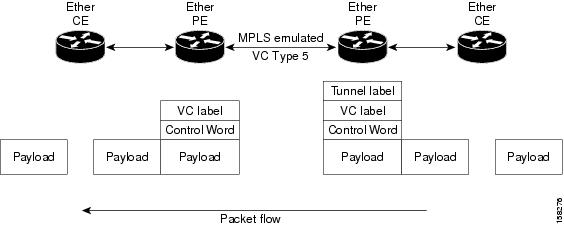
In Ethernet port mode, both ends of a pseudowire are connected to Ethernet ports. In this mode, the port is tunneled over the pseudowire or, using local switching (also known as an attachment circuit-to-attachment circuit cross-connect) switches packets or frames from one attachment circuit (AC) to another AC attached to the same PE node.

The following figure provides an example of Ethernet port mode.

Figure 1. Ethernet Port Mode Packet Flow

Ethernet Port Mode Packet Flow

Ethernet Remote Port Shutdown

Ethernet remote port shutdown provides a mechanism for the detection and propagation of remote link failure for port mode EoMPLS on a Cisco NCS 6000 Series Router line card. This lets a service provider edge router on the local end of an Ethernet-over-MPLS (EoMPLS) pseudowire detect a cross-connect or remote link failure and cause the shutdown of the Ethernet port on the local customer edge router. Shutting down the Ethernet port on the local customer edge router prevents or mitigates a condition where that router would otherwise lose data by forwarding traffic continuously to the remote failed link, especially if the link were configured as a static IP route (see following figure)..

Figure 2. Remote Link Outage in EoMPLS Wide Area Network

Remote Link Outage in EoMPLS Wide Area Network

To enable this functionality, see the l2transport propagate command in MPLS Command Reference for Cisco NCS 6000 Series Routers.

VLAN Mode

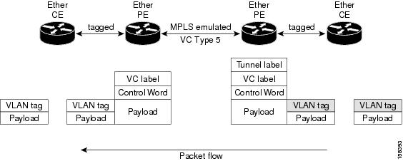
In VLAN mode, each VLAN on a customer-end to provider-end link can be configured as a separate L2VPN connection using virtual connection (VC) type 4 or VC type 5. VC type 5 is the default mode.

As illustrated in the following figure, the Ethernet PE associates an internal VLAN-tag to the Ethernet port for switching the traffic internally from the ingress port to the pseudowire; however, before moving traffic into the pseudowire, it removes the internal VLAN tag.

Figure 3. VLAN Mode Packet Flow

VLAN Mode Packet Flow

At the egress VLAN PE, the PE associates a VLAN tag to the frames coming off of the pseudowire and after switching the traffic internally, it sends out the traffic on an Ethernet trunk port.


Note


Because the port is in trunk mode, the VLAN PE doesn't remove the VLAN tag and forwards the frames through the port with the added tag.


Inter-AS Mode

Inter-AS is a peer-to-peer type model that allows extension of VPNs through multiple provider or multi-domain networks. This lets service providers peer up with one another to offer end-to-end VPN connectivity over extended geographical locations.

EoMPLS support can assume a single AS topology where the pseudowire connecting the PE routers at the two ends of the point-to-point EoMPLS cross-connects resides in the same autonomous system; or multiple AS topologies in which PE routers can reside on two different ASs using iBGP and eBGP peering.

The following figure illustrates MPLS over Inter-AS with a basic double AS topology with iBGP/LDP in each AS.

Figure 4. EoMPLS over Inter-AS: Basic Double AS Topology

QinQ Mode

QinQ is an extension of 802.1Q for specifying multiple 802.1Q tags (IEEE 802.1QinQ VLAN Tag stacking). Layer 3 VPN service termination and L2VPN service transport are enabled over QinQ sub-interfaces.

The Cisco NCS 6000 Series Routers implement the Layer 2 tunneling or Layer 3 forwarding depending on the subinterface configuration at provider edge routers. This function only supports up to two QinQ tags on the SPA and fixed PLIM:

  • Layer 2 QinQ VLANs in L2VPN attachment circuit: QinQ L2VPN attachment circuits are configured under the Layer 2 transport subinterfaces for point-to-point EoMPLS based cross-connects using virtual circuit type 4 pseudowires and point-to-point local-switching-based cross-connects including full interworking support of QinQ with 802.1q VLANs and port mode.

  • Layer 3 QinQ VLANs: Used as a Layer 3 termination point, both VLANs are removed at the ingress provider edge and added back at the remote provider edge as the frame is forwarded.

Layer 3 services over QinQ include:

  • IPv4 unicast and multicast

  • IPv6 unicast and multicast

  • MPLS


Note


The Cisco NCS 6000 Series Router does not support: bundle attachment circuits and Hot Standby Router Protocol (HSRP) or Virtual Router Redundancy Protocol (VRRP) on QinQ subinterfaces.


In QinQ mode, each CE VLAN is carried into an SP VLAN. QinQ mode should use VC type 5, but VC type 4 is also supported. On each Ethernet PE, you must configure both the inner (CE VLAN) and outer (SP VLAN).

The following figure illustrates QinQ using VC type 4.

Figure 5. EoMPLS over QinQ Mode


High Availability

L2VPN uses control planes in both route processors and line cards, as well as forwarding plane elements in the line cards.


Note


The l2tp_mgr process does not support high availability.


The availability of L2VPN meets these requirements:

  • A control plane failure in either the route processor or the line card will not affect the circuit forwarding path.

  • The router processor control plane supports failover without affecting the line card control and forwarding planes.

  • L2VPN integrates with existing Label Distribution Protocol (LDP) graceful restart mechanism.

Preferred Tunnel Path

Preferred tunnel path functionality lets you map pseudowires to specific traffic-engineering tunnels. Attachment circuits are cross-connected to specific MPLS traffic engineering tunnel interfaces instead of remote PE router IP addresses (reachable using IGP or LDP). Using preferred tunnel path, it is always assumed that the traffic engineering tunnel that transports the L2 traffic runs between the two PE routers (that is, its head starts at the imposition PE router and its tail terminates on the disposition PE router).


Note


  • Currently, preferred tunnel path configuration applies only to MPLS encapsulation.

  • The fallback enable option is supported.


Pseudowire Redundancy

Pseudowire redundancy allows you to configure your network to detect a failure in the network and reroute the Layer 2 service to another endpoint that can continue to provide service. This feature provides the ability to recover from a failure of either the remote provider edge (PE) router or the link between the PE and customer edge (CE) routers.

L2VPNs can provide pseudowire resiliency through their routing protocols. When connectivity between end-to-end PE routers fails, an alternative path to the directed LDP session and the user data takes over. However, there are some parts of the network in which this rerouting mechanism does not protect against interruptions in service.

Pseudowire redundancy enables you to set up backup pseudowires. You can configure the network with redundant pseudowires and redundant network elements.

Prior to the failure of the primary pseudowire, the ability to switch traffic to the backup pseudowire is used to handle a planned pseudowire outage, such as router maintenance.


Note


Pseudowire redundancy is provided only for point-to-point Virtual Private Wire Service (VPWS) pseudowires.

Flow Aware Transport Pseudowire (FAT PW)

Flow Aware Transport Pseudowires (FAT PW) are used to load-balance traffic in the core when equal cost multipaths (ECMP) are used. The flow, in this context, refers to a sequence of packets that have the same source and destination pair. The packets are transported from a source provider edge (PE) to a destination PE.

The following figure shows a FAT PW with two flows distributing over ECMPs and bundle links.

Figure 6. FAT PW with two flows distributing over ECMPs and Bundle-Links

The MPLS labels add an additional label to the stack, called the flow label, which contains the flow information of a virtual circuit (VC). A flow label is a unique identifier that distinguishes a flow within the PW, and is derived from the IP payload of a packet. The flow label contains the end of label stack (EOS) bit set and inserted after the VC label and before the control word (if any). The ingress PE calculates and forwards the flow label. The FAT PW configuration enables the flow label. The egress PE discards the flow label such that no decisions are taken based on that label.

Core routers perform load balancing using the flow-label in the FAT PW with other information like MAC address and IP address. The flow-label adds greater entropy to improve traffic load balancing. Therefore, it’s possible to distribute flows over ECMPs and link bundles.

You cannot send MPLS OAM ping traffic over a FAT PW, since there is no flow label support for MPLS OAM.

L2VPN Nonstop Routing

The L2VPN Nonstop Routing (NSR) feature avoids label distribution path (LDP) sessions from flapping on events such as process failures (crash) and route processor failover (RP FO). NSR on process failure (crash) is supported by performing RP FO, if you have enabled NSR using NSR process failure switchover.

NSR enables the router (where failure has occurred) to maintain the control plane states without a graceful restart (GR). NSR, by definition, does not require any protocol extension and typically uses Stateful Switch Over (SSO) to maintain it’s control plane states.


Note


NSR is enabled by default for L2VPN on Cisco IOS XR 64 bit operating system. You cannot configure the nsr command under L2VPN configuration submode.


How to Implement Point to Point Layer 2 Services

This section describes the tasks required to implement Point to Point Layer 2 Services:

Configuring an Interface or Connection for Point to Point Layer 2 Services

Perform this task to configure an interface or a connection for Point to Point Layer 2 Services.

SUMMARY STEPS

  1. configure
  2. interface type interface-path-id
  3. l2transport
  4. exit
  5. interface type interface-path-id.subinterface l2transport
  6. encapsulation dot1q vlan-id
  7. Use the commit or end command.

DETAILED STEPS


Step 1

configure

Example:


RP/0/RP0/CPU0:router# configure

Enters the XR Config mode.

Step 2

interface type interface-path-id

Example:


RP/0/RP0/CPU0:router(config)# interface TenGigE 0/0/0/0

Enters interface configuration mode and configures an interface.

Step 3

l2transport

Example:


RP/0/RP0/CPU0:router(config-if)# l2transport

Enables L2 transport on the selected interface.

Step 4

exit

Example:


RP/0/RP0/CPU0:router(config-if-l2)# exit

Exits the current configuration mode.

Step 5

interface type interface-path-id.subinterface l2transport

Example:


RP/0/RP0/CPU0:router(config)# interface TenGigE 0/0/0/0.1 l2transport

Enters subinterface configuration mode and configures the subinterface as a layer 2 interface.

Step 6

encapsulation dot1q vlan-id

Example:

RP/0/RP0/CPU0:router(config-if)# encapsulation dot1q vln1

Assigns native VLAN ID to an interface trunking 802.1Q VLAN traffic.

Step 7

Use the commit or end command.

commit - Saves the configuration changes and remains within the configuration session.

end - Prompts user to take one of these actions:

  • Yes - Saves configuration changes and exits the configuration session.
  • No - Exits the configuration session without committing the configuration changes.
  • Cancel - Remains in the configuration mode, without committing the configuration changes.

Configuring Static Point-to-Point Cross-Connects


Note


Consider this information about cross-connects when you configure static point-to-point cross-connects:
  • An cross-connect is uniquely identified with the pair; the cross-connect name must be unique within a group.

  • A segment (an attachment circuit or pseudowire) is unique and can belong only to a single cross-connect.

  • A static VC local label is globally unique and can be used in one pseudowire only.

  • No more than 16,000 cross-connects can be configured per router.


Note


Static pseudowire connections do not use LDP for signaling.


Perform this task to configure static point-to-point cross-connects.

SUMMARY STEPS

  1. configure
  2. l2vpn
  3. xconnect group group-name
  4. p2p xconnect-name
  5. interface type interface-path-id
  6. neighbor ip-address pw-id pseudowire-id
  7. mpls static label local { value } remote { value }
  8. Use the commit or end command.
  9. show l2vpn xconnect group group name

DETAILED STEPS


Step 1

configure

Example:


RP/0/RP0/CPU0:router# configure

Enters the XR Config mode.

Step 2

l2vpn

Example:


RP/0/RP0/CPU0:router(config)# l2vpn

Enters L2VPN configuration mode.

Step 3

xconnect group group-name

Example:


RP/0/RP0/CPU0:router(config-l2vpn)# xconnect group 


Enters the name of the cross-connect group.

Step 4

p2p xconnect-name

Example:


RP/0/RP0/CPU0:router(config-l2vpn-xc)# p2p vlan1

Enters a name for the point-to-point cross-connect.

Step 5

interface type interface-path-id

Example:


RP/0/RP0/CPU0:router(config-l2vpn-xc-p2p)# interface TenGigE 0/0/0/0.1

Specifies the interface type and instance.

Step 6

neighbor ip-address pw-id pseudowire-id

Example:


RP/0/RP0/CPU0:routerr(config-l2vpn-xc-p2p)# neighbor 2.2.2.2 pw-id 2000

Configures the pseudowire segment for the cross-connect.

Optionally, you can disable the control word or set the transport-type to Ethernet or VLAN.

Step 7

mpls static label local { value } remote { value }

Example:


RP/0/RP0/CPU0:router(config-l2vpn-xc-p2p-pw)# mpls static label local 699 remote 890

Configures local and remote label ID values.

Step 8

Use the commit or end command.

commit - Saves the configuration changes and remains within the configuration session.

end - Prompts user to take one of these actions:

  • Yes - Saves configuration changes and exits the configuration session.
  • No - Exits the configuration session without committing the configuration changes.
  • Cancel - Remains in the configuration mode, without committing the configuration changes.

Step 9

show l2vpn xconnect group group name

Example:

RP/0/RP0/CPU0:show l2vpn xconnect group vlan_grp_1

Displays the name of the Point-to-Point cross-connect group you created.


Configuring Dynamic Point-to-Point Cross-Connects

Perform this task to configure dynamic point-to-point cross-connects.


Note


For dynamic cross-connects, LDP must be up and running.


SUMMARY STEPS

  1. configure
  2. l2vpn
  3. xconnect group group-name
  4. p2p xconnect-name
  5. interworking ipv4
  6. interface type interface-path-id
  7. neighbor ip-address pw-id pseudowire-id
  8. Use the commit or end command.

DETAILED STEPS


Step 1

configure

Example:


RP/0/RP0/CPU0:router# configure

Enters the XR Config mode.

Step 2

l2vpn

Example:


RP/0/RP0/CPU0:router(config)# l2vpn

Enters L2VPN configuration mode.

Step 3

xconnect group group-name

Example:


RP/0/RP0/CPU0:router(config-l2vpn)# xconnect group grp_1

Enters the name of the cross-connect group.

Step 4

p2p xconnect-name

Example:


RP/0/RP0/CPU0:router(config-l2vpn-xc)# p2p vlan1

Enters a name for the point-to-point cross-connect.

Step 5

interworking ipv4

Example:


RP/0/RP0/CPU0:router(config-l2vpn-xc)# interworking ipv4 


Configure the interworking for IPv4.

Step 6

interface type interface-path-id

Example:


RP/0/RP0/CPU0:router(config-l2vpn-xc-p2p)# interface GigabitEthernet0/0/0/0.1

Specifies the interface type ID. The choices are:

  • GigabitEthernet: GigabitEthernet/IEEE 802.3 interfaces.

  • TenGigE: TenGigabitEthernet/IEEE 802.3 interfaces.

  • CEM: Circuit Emulation interface

Step 7

neighbor ip-address pw-id pseudowire-id

Example:

RP/0/RP0/CPU0:router(config-l2vpn-xc-p2p)# neighbor 2.2.2.2 pw-id 2000

Configures the pseudowire segment for the cross-connect.

Optionally, you can disable the control word or set the transport-type to Ethernet or VLAN.

Step 8

Use the commit or end command.

commit - Saves the configuration changes and remains within the configuration session.

end - Prompts user to take one of these actions:

  • Yes - Saves configuration changes and exits the configuration session.
  • No - Exits the configuration session without committing the configuration changes.
  • Cancel - Remains in the configuration mode, without committing the configuration changes.

Configuring Inter-AS

The Inter-AS configuration procedure is identical to the L2VPN cross-connect configuration tasks (see “Configuring Static Point-to-Point Cross-Connects” section and “Configuring Dynamic Point-to-Point Cross-Connects” section) except that the remote PE IP address used by the cross-connect configuration is now reachable through iBGP peering.


Note


You must be knowledgeable about IBGP, EBGP, and ASBR terminology and configurations to complete this configuration.


Configuring Preferred Tunnel Path

This procedure describes how to configure a preferred tunnel path.

Note


The tunnel used for the preferred path configuration is an MPLS Traffic Engineering (MPLS-TE) tunnel.

SUMMARY STEPS

  1. configure
  2. l2vpn
  3. pw-class {name }
  4. encapsulation mpls
  5. preferred-path {interface } {tunnel-ip value | tunnel-te value | tunnel-tp value } [fallback disable ]
  6. Use the commit or end command.

DETAILED STEPS


Step 1

configure

Example:


RP/0/RP0/CPU0:router# configure

Enters the configuration mode.

Step 2

l2vpn

Example:


RP/0/RP0/CPU0:router(config)# l2vpn

Enters L2VPN configuration mode.

Step 3

pw-class {name }

Example:


RP/0/RP0/CPU0:router(config-l2vpn)# pw-class path1

Configures the pseudowire class name.

Step 4

encapsulation mpls

Example:


RP/0/RP0/CPU0:router(config-l2vpn-pwc)# encapsulation mpls

Configures the pseudowire encapsulation to MPLS.

Step 5

preferred-path {interface } {tunnel-ip value | tunnel-te value | tunnel-tp value } [fallback disable ]

Example:


RP/0/RP0/CPU0:router(config-l2vpn-pwc-encap-mpls)# preferred-path interface tunnel-te 11 fallback disable

Configures preferred path tunnel settings. If the fallback disable configuration is used and once the TE/TP tunnel is configured as the preferred path goes down, the corresponding pseudowire can also go down.

Step 6

Use the commit or end command.

commit - Saves the configuration changes and remains within the configuration session.

end - Prompts user to take one of these actions:

  • Yes - Saves configuration changes and exits the configuration session.
  • No - Exits the configuration session without committing the configuration changes.
  • Cancel - Remains in the configuration mode, without committing the configuration changes.

Enabling Load Balancing with ECMP and FAT PW

Perform this task to enable load balancing with ECMP and FAT PW.

SUMMARY STEPS

  1. configure
  2. l2vpn
  3. pw-class {name}
  4. encapsulation mpls
  5. load-balancing flow-label both
  6. Use the commit or end command.

DETAILED STEPS


Step 1

configure

Example:

RP/0/RP0/CPU0:router# configure

Enters the XR Config mode.

Step 2

l2vpn

Example:

RP/0/RP0/CPU0:router(config)# l2vpn

Enters the L2VPN configuration mode.

Step 3

pw-class {name}

Example:

RP/0/RP0/CPU0:router(config-l2vpn)# pw-class FAT_PW

Configures the pseudowire class name.

Step 4

encapsulation mpls

Example:

RP/0/RP0/CPU0:router(config-l2vpn-pwc)# encapsulation mpls

Configures the pseudowire encapsulation to MPLS.

Step 5

load-balancing flow-label both

Example:

RP/0/RP0/CPU0:router(config-l2vpn-pwc-encap-
mpls)# load-balancing flow-label both

Enables load-balancing on ECMPs. Also, enables the imposition and disposition of flow labels for the pseudowire.

Step 6

Use the commit or end command.

commit - Saves the configuration changes and remains within the configuration session.

end - Prompts user to take one of these actions:

  • Yes - Saves configuration changes and exits the configuration session.
  • No - Exits the configuration session without committing the configuration changes.
  • Cancel - Remains in the configuration mode, without committing the configuration changes.

Configuring L2VPN Nonstop Routing

Perform this task to configure L2VPN Nonstop Routing.

SUMMARY STEPS

  1. configure
  2. l2vpn
  3. nsr
  4. logging nsr
  5. Use the commit or end command.

DETAILED STEPS


Step 1

configure

Example:

RP/0/RP0/CPU0:router# configure

Enters XR Config mode.

Step 2

l2vpn

Example:


RP/0/RP0/CPU0:router(config)# l2vpn

Enters the XR Config mode.

Step 3

nsr

Example:


RP/0/RP0/CPU0:router (config-l2vpn)# nsr

Enables L2VPN nonstop routing.

Step 4

logging nsr

Example:


RP/0/RP0/CPU0:router (config-l2vpn)# logging nsr

Enables logging of NSR events.

Step 5

Use the commit or end command.

commit - Saves the configuration changes and remains within the configuration session.

end - Prompts user to take one of these actions:

  • Yes - Saves configuration changes and exits the configuration session.
  • No - Exits the configuration session without committing the configuration changes.
  • Cancel - Remains in the configuration mode, without committing the configuration changes.

Configure MPLS LDP Nonstop Routing

Perform this task to enable Label Distribution Protocol (LDP) Nonstop Routing (NSR) for synchronizing label information between active and standby LDPs. From Release 6.1.1 onwards, with the introduction of stateful LDP feature, you must explicitly configure LDP NSR to synchronize label information between active and standby LDPs.

SUMMARY STEPS

  1. configure
  2. mpls ldp
  3. nsr
  4. Use the commit or end command.

DETAILED STEPS


Step 1

configure

Example:

RP/0/RP0/CPU0:router# configure

Enters XR Config mode.

Step 2

mpls ldp

Example:


RP/0/RP0/CPU0:router(config)# mpls ldp

Enters MPLS LDP configuration mode.

Step 3

nsr

Example:


RP/0/RP0/CPU0:router(config-ldp)# nsr

Enables LDP nonstop routing.

Step 4

Use the commit or end command.

commit - Saves the configuration changes and remains within the configuration session.

end - Prompts user to take one of these actions:

  • Yes - Saves configuration changes and exits the configuration session.

  • No - Exits the configuration session without committing the configuration changes.

  • Cancel - Remains in the configuration mode, without committing the configuration changes.


Configuring Flow Aware Transport Pseudowire

This section provides information on

Enabling Load Balancing with ECMP and FAT PW for VPWS

Perform this task to enable load balancing with ECMP and FAT PW for VPWS. Creating a PW-Class in L2VPN configuration leads to load-balancing.

SUMMARY STEPS

  1. configure
  2. l2vpn
  3. pw-class { name }
  4. encapsulation mpls
  5. load-balancing flow-label { both | code | receive | transmit } [ static ]
  6. exit
  7. exit
  8. xconnect group group-name
  9. p2p xconnect-name
  10. interface type interface-path-id
  11. neighbor A.B.C.D pw-id pseudowire-id
  12. pw-class class-name
  13. Use the commit or end command.

DETAILED STEPS


Step 1

configure

Example:
RP/0/RP0/CPU0:router# configure

Enters the XR Config mode.

Step 2

l2vpn

Example:

RP/0/RP0/CPU0:router(config)# l2vpn

Enters L2VPN configuration mode.

Step 3

pw-class { name }

Example:

RP/0/RSP0/CPU0:router(config-l2vpn)# pw-class path1

Configures the pseudowire class template name to use for the pseudowire.

Step 4

encapsulation mpls

Example:

RP/0/RP0/CPU0:router(config-l2vpn-pwc)# encapsulation mpls

Configures the pseudowire encapsulation to MPLS.

Step 5

load-balancing flow-label { both | code | receive | transmit } [ static ]

Example:

RP/0/RP0/CPU0:router(config-l2vpn-pwc-mpls)# load-balancing flow-label both

Enables load-balancing on ECMPs. Also, enables the imposition and disposition of flow labels for the pseudowire.

Note

 
If the static keyword is not specified, end to end negotiation of the FAT PW is enabled.

Step 6

exit

Example:

RP/0/RP0/CPU0:router(config-l2vpn-pwc-mpls)#exit
RP/0/RP0/CPU0:router(config-l2vpn-pwc)#

Exits the pseudowire encapsulation submode and returns the router to the parent configuration mode.

Step 7

exit

Example:

RP/0/RP0/CPU0:router(config-l2vpn-pwc)#exit
RP/0/RP0/CPU0:router(config-l2vpn)#

Exits the pseudowire submode and returns the router to the l2vpn configuration mode.

Step 8

xconnect group group-name

Example:

RP/0/RP0/CPU0:router(config-l2vpn)# xconnect group grp1
RP/0/RP0/CPU0:router(config-l2vpn-xc)#

Specifies the name of the cross-connect group.

Step 9

p2p xconnect-name

Example:

RP/0/RP0/CPU0:router(config-l2vpn-xc)# p2p vlan1
RP/0/RP0/CPU0:router(config-l2vpn-xc-p2p)#

Specifies the name of the point-to-point cross-connect.

Step 10

interface type interface-path-id

Example:

RP/0/RP0/CPU0:router(config-l2vpn-xc-p2p)# interface TenGigE 0/0/0/0.1

Specifies the interface type and instance.

Step 11

neighbor A.B.C.D pw-id pseudowire-id

Example:

RP/0/RP0/CPU0:router(config-l2vpn-xc-p2p)# neighbor 10.2.2.2 pw-id 2000

Configures the pseudowire segment for the cross-connect.

Use the A.B.C.D argument to specify the IP address of the cross-connect peer.

Note

 
A.B.C.D can be a recursive or non-recursive prefix.

Step 12

pw-class class-name

Example:

RP/0/RP0/CPU0:router(config-l2vpn-xc-p2p-pw)# pw-class path1

Associates the pseudowire class with this pseudowire.

Step 13

Use the commit or end command.

commit - Saves the configuration changes and remains within the configuration session.

end - Prompts user to take one of these actions:

  • Yes - Saves configuration changes and exits the configuration session.
  • No - Exits the configuration session without committing the configuration changes.
  • Cancel - Remains in the configuration mode, without committing the configuration changes.

Configuration Examples for Point to Point Layer 2 Services

In the following example, two traffic classes are created and their match criteria are defined. For the first traffic class called class1, ACL 101 is used as the match criterion. For the second traffic class called class2, ACL 102 is used as the match criterion. Packets are checked against the contents of these ACLs to determine if they belong to the class.

This section includes the following configuration examples:

L2VPN Interface Configuration: Example

This example shows how to configure an L2VPN interface:

configure
 interface TenGigE 0/0/0/0.1 l2transport
 encapsulation dot1q 1
 end

Point-to-Point Cross-connect Configuration: Examples

This section includes configuration examples for both static and dynamic p2p cross-connects.

Static Configuration

This example shows how to configure a static point-to-point cross-connect:


configure
 l2vpn
  xconnect group vlan_grp_1
   p2p vlan1
   interworking ipv4
   interface TenGigE 0/0/0/0.1
   neighbor 2.2.2.2 pw-id 2000
    mpls static label local 699 remote 890
    commit

Dynamic Configuration

This example shows how to configure a dynamic point-to-point cross-connect:

configure
  l2vpn
   xconnect group vlan_grp_1
    p2p vlan1
    interface TenGigE 0/0/0/0.1
    neighbor 2.2.1.1 pw-id 1
commit

Inter-AS: Example

This example shows how to set up an AC to AC cross-connect from AC1 to AC2:

Preferred Path: Example

This example shows how to configure preferred tunnel path:

configure
l2vpn
pw-class path1
encapsulation mpls
preferred-path interface tunnel-ip value  fallback disable

Enabling Load Balancing with FAT PW: Example

This sample configuration shows how to enable load balancing with FAT PW for VPWS.

l2vpn
pw-class class1
    encapsulation mpls
        load-balancing flow-label transmit
    !
 !
pw-class class2
    encapsulation mpls
        load-balancing flow-label both
    !

xconnect group group1
    p2p p1
        interface TenGigE 0/0/0/0.1
        neighbor 10.0.0.1 pw-id 1
            pw-class class1
        !
    !
! 

Configuring L2VPN Nonstop Routing: Example

This example shows how to configure L2VPN Nonstop Routing.

config
l2vpn
 nsr
 logging nsr 

Configuring Flow Aware Transport Pseudowire: Example

This sample configuration shows how to enable load balancing with FAT PW for VPWS.

l2vpn
pw-class class1
    encapsulation mpls
        load-balancing flow-label transmit
    !
 !
pw-class class2
    encapsulation mpls
        load-balancing flow-label both
    !

xconnect group group1
    p2p p1
        interface TenGigE 0/0/0/0.1
        neighbor 1.1.1.1 pw-id 1
            pw-class class1
        !
    !
! 

Layer 2 VPN Load Balancing for MPLS

Table 1. Feature History Table

Feature Name

Release Information

Feature Description

Layer 2 VPN Load Balancing for MPLS

Release 7.6.3

You can now configure load balancing on Virtual Private Wire Service (VPWS), using virtual circuit (VC) label-based hashing and 7-tuple IP-based hashing, for MPLS packets. This feature allows for better and uniform traffic distribution across ECMP paths in an MPLS network.

In previous releases, the load balancing could be configured only for IP packets.

Load balancing on traffic flow is required for better and uniform traffic distribution over multiple links in a network. This allows to maximize the usage of network resources. Load balancing can be flow-based according to source or destination IP addresses, or source or destination MAC addresses.

You can configure load balancing for MPLS packets by enabling virtual circuit (VC) label-based hashing and 7-tuple IP-based hashing algorithm on Virtual Private Wire Service (VPWS).

For more information on 7-tuple hash algorithm, see the Per-Flow Load Balancing section in the IP Addresses and Services Configuration Guide for Cisco NCS 6000 Series Routers.

Restrictions for L2VPN Load Balancing for MPLS

Load balancing for MPLS packets is supported only on Virtual Private Wire Service (VPWS) and not supported on Virtual Private LAN service (VPLS).

Configure L2VPN Load Balancing for MPLS

Prerequisites

  • Ensure that you have enabled load balancing with 7-tuple hash algorithm using the cef load-balancing fields L4 command.

To enable load balancing for MPLS networks, perform the following tasks:

  • Configure L2VPN Nonstop Routing (NSR). The NSR avoids label distribution path (LDP) sessions from flapping on events such as process failures and route processor failover.

  • Configure a pseudowire (PW) class and configure the encapsulation type of the PW class as MPLS.

  • Optionally, you can disable the control word and set the transport-type to Ethernet.

  • Configure load balancing with imposition and disposition of flow labels for the pseudowire using the load-balancing flow-label both command.

  • Configure the source IP address for PW class to establish L2 VPN connectivity.

  • Configure L2 VPN cross-connect group and associate the PW class with the pseudowire segment.

Configuration Example

/* Configure 7-tuple hash algorithm */

Router# configure
Router(config)# cef load-balancing fields L4
Router(config)# commit
/* Configure L2VPN NSR */
Router(config)# l2vpn
Router(config-l2vpn)# logging
Router(config-l2vpn-log)# nsr
Router(config-l2vpn-log)# exit
/* Configure PW class and load balancing */

Router(config-l2vpn)# pw-class pwhe
Router(config-l2vpn-pwc)# encapsulation mpls
Router(config-l2vpn-pwc-mpls)# control-word
Router(config-l2vpn-pwc-mpls)# transport-mode ethernet
Router(config-l2vpn-pwc-mpls)# load-balancing flow-label both
Router(config-l2vpn-pwc-mpls)# exit
Router(config-l2vpn-pwc)# ipv4 source 10.2.1.1
Router(config-l2vpn-pwc)# commit
Router(config-l2vpn-pwc)# exit
/* Configure L2VPN cross-connect and associate the PW class */
Router(config-l2vpn)# xconnect group XC1
Router(config-l2vpn-xc)# p2p pw_30000
Router(config-l2vpn-xc-p2p)# interface HundredGigE0/2/0/5
Router(config-l2vpn-xc-p2p)# neighbor ipv4 5.5.5.5 pw-id 30000
Router(config-l2vpn-xc-p2p-pw)# pw-class pwhe

Running Configuration

l2vpn     
 logging  
  nsr     
 !        
 pw-class pwhe
  encapsulation mpls
   control-word
   transport-mode ethernet
   load-balancing
    flow-label both
   !
   ipv4 source 10.2.1.1
xconnect group XC1
p2p pw_30000
interface HundredGigE0/2/0/5
neighbor ipv4 5.5.5.5 pw-id 30000
pw-class pwhe